EP2207148B1 - Induktive Messanordnung für Freifall-Münzgeräte - Google Patents
Induktive Messanordnung für Freifall-Münzgeräte Download PDFInfo
- Publication number
- EP2207148B1 EP2207148B1 EP09013874.4A EP09013874A EP2207148B1 EP 2207148 B1 EP2207148 B1 EP 2207148B1 EP 09013874 A EP09013874 A EP 09013874A EP 2207148 B1 EP2207148 B1 EP 2207148B1
- Authority
- EP
- European Patent Office
- Prior art keywords
- coil
- inductive measuring
- measuring assembly
- winding
- receiving
- Prior art date
- Legal status (The legal status is an assumption and is not a legal conclusion. Google has not performed a legal analysis and makes no representation as to the accuracy of the status listed.)
- Active
Links
Images

Classifications
-
- G—PHYSICS
- G07—CHECKING-DEVICES
- G07D—HANDLING OF COINS OR VALUABLE PAPERS, e.g. TESTING, SORTING BY DENOMINATIONS, COUNTING, DISPENSING, CHANGING OR DEPOSITING
- G07D5/00—Testing specially adapted to determine the identity or genuineness of coins, e.g. for segregating coins which are unacceptable or alien to a currency
- G07D5/08—Testing the magnetic or electric properties
Definitions
- the invention relates to an inductive measuring arrangement for coin testing in free-fall coin devices according to claim 1.
- Inductive measuring probes preferably consist of a transmitting coil and a receiving coil, which are arranged on both sides of a coin channel.
- a transmissive and a reflexive measurement In this inductive measurement, a distinction is made between a transmissive and a reflexive measurement.
- transmissive measurement the field of the transmitting coil passes through a coin. From the attenuation of the field, the receiving coil measures at least one specific parameter of the coin.
- the transmit and receive coils are located on one side of the free fall path. These Measurement detects the surface and / or the near-surface calculation of the coins as, for example, specific outer layers.
- a coil assembly for a coin validator with a transmitting and receiving coil in elongated rectangular shape is known, which are extending transversely to the direction of the coins.
- the receiving coil has a one-piece ferrite shell with a cylindrical core portion for the lower portion and an oval or elongated core portion above the cylindrical core portion, further comprising an elongated bobbin, which is attachable to the ferrite shell.
- the coins are guided along an inclined relative to the horizontal Münzlaufbahn.
- EP 1 873 725 A2 a coin validator in a free fall coin known.
- a plurality of sensors is provided, each of which has a coil-wrapped core.
- a free fall coin known with an inductive measuring device for the coin validation.
- two coil assemblies are provided, and there is provided a ferrite core having an E-shaped cross-section which accommodates the coils.
- the invention has for its object to provide an inductive measuring arrangement for the coin validation in free-fall coins, which is well suited for both a transmissive and a reflective measurement of coins in free-fall coins.
- two elongated coils are arranged coaxially juxtaposed in an E-shaped pot core.
- the middle leg of the E-shaped shell core extends through a first coil and not at all or partially into the second outer coil.
- an elongated linear bobbin made of plastic which has two axially spaced circumferential grooves for receiving at least one coil winding and within the area surrounded by the grooves an elongated axially directed recess on one side of the bobbin, wherein the depth of the recess may extend at least to the facing groove.
- a shell of ferrite is E-shaped in section and takes the bobbin between its outer legs approximately fitting. The middle leg extends into the recess.
- Such an inductive measuring arrangement is suitable for both transmissive and reflexive measurement.
- the transmissive measurement only one coil winding as a transmitting coil and one coil winding as a receiving coil on opposite sides of the drop path are needed.
- the reflective measurement a coil body is required on at least one side, in which a transmitting and a receiving coil winding are arranged in each case a groove.
- a reflexive and transmissive measurement is made respectively on the opposite sides of the fall path.
- the measuring arrangement according to the invention is used for measuring free-fall coins. Since the fall path from grounds should be as short as possible, it is of great advantage if the elongated coil shape has a very narrow width. Preferably, the aspect ratio is 4: 1, that is, the long side is four times as large as the narrow side. This allows an effective measuring width of the channel. In addition, the height is kept small. A small dimension in the direction of fall also has the advantage that a short measurement time is achieved, so that a high pick-up frequency is possible. Finally, it can be distinguished relatively well between ring and core material in so-called Bicolor coins by the low measurement height of the coils. In the edge region, only the ring material and in the central region essentially also the core material is detected.
- the middle core section extends only in the region of the respective transmitting coil, but preferably not into the receiving coil, a smaller coupling between the transmitting coil and the receiving coil is achieved in the reflexive measurement.
- the decoupling is not as extensive as in the known coil arrangement described above, in which the transmitting coil is wound on an elongated bobbin and the receiving coil is arranged in a recess of significantly smaller diameter on the front side of the core, nevertheless with an inductive measuring arrangement according to Invention to obtain an optimal measurement result, if you want to perform both a transmissive and a reflective measurement on opposite sides of a free fall path in a free fall coin device.
- the bobbin is preferably formed integrally from a suitable plastic material, wherein according to an embodiment of the invention to the bobbin extending beyond one end of the bobbin addition approach is formed, which receives solder pins in preformed holes, which in turn connectable with wire ends of the coil winding are.
- tabs of small thickness are formed on opposite sides of the bobbin in the central region, which cover the coil winding laterally protective after its folding over at least one groove. After forming the tabs initially protrude laterally outward and are folded around only after winding the coil winding. The tabs protect the windings in particular when inserting the bobbin in the ferrite shell. In addition, they allow the clamping of the bobbin in the shell. Gluing is not necessary.
- Two walls 10, 12 of a free fall coin device define a drop path 14 for coins, one of which is shown at 16.
- two inductive measuring arrangements 18, 20 are arranged, each having a transmitting coil 22, 24 and a receiving coil 26, 28.
- the coils 22 to 28 extend linearly perpendicular to the plane of the drawing over the entire width of the drop path 14. As a result, coins of any diameter always fall through the measuring range of the measuring arrangements 18, 20.
- the basic structure of the measuring arrangements according to Fig. 1 is known.
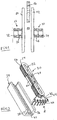
- Fig. 2 is an elongated coil assembly 30 can be seen with a bobbin 32 which receives in two coaxial grooves coil windings 54, 56. This will be discussed in more detail below.
- the coil assembly 30 is inserted into a ferrule core 34 which is E-shaped in cross-section with two outer legs 36, 38 and a middle leg 40. As can be seen, the middle leg 40 extends less than half the height of the legs 36 38.
- the bobbin 32 is integrally molded from a suitable plastic material and has at one end a triangular neck 42 which in holes 44th Solder pins 46 receives.
- the solder pins are angular. With the solder pins 46, the wire ends of the coil windings 54, 56 are connected by being soldered to them. To the coil winding 56 may also occur another winding that meets the compensation purposes.
- the coil is preferably wound bifilar.
- tabs 48, 50 are integrally formed on the bobbin 32 in the middle in view of the longitudinal extension of the bobbin 32. They are folded after winding the coils and cover the coils in the central region, so that the coils are protected when inserted into the shell core.
- the bobbin 32 has two circumferential grooves 51, 52 which are trapezoidal in section. They expand to the outside.
- the grooves 51, 52 each receive a coil 54 and 56, as well as in Fig. 4 to recognize.
- an elongated axial recess 60 is formed on one side of the bobbin 32. It extends largely over the entire length of the bobbin. However, the depth of the recess 60 goes only slightly beyond the groove 52 to central groove portions 58.
- the bobbin 32 has a series of longitudinally spaced webs 62 on.
- the coil assembly 30 can be inserted into the shell core, wherein the legs 36, 38 with the opposite surface of the bobbin 32 is flush. This area is then the fall path 14 in FIG. 1 faces.
- the middle leg 40 extends into the recess 60 and therefore covers only the groove 52, but not the groove 51st
- the coil 56 When used as an inductive measuring arrangement, the coil 56 is the transmitting coil, and the coil 54, the receiving coil. It can be seen that there is less coupling between the transmitting coils 54 and the receiving coil 56 than in conventional coil arrangements in which the core extends through both coils.
- a reflective measurement of the coins is therefore possible.
- a reflexive measurement of both sides of the fall path is mandatory if the coins do not have identical outer layers and it is not clear which coin surface is facing which measurement arrangement.
- the distance of the coins to the receiving coil is included in the measurement, which can be compensated by a measurement on both sides, as well as in the transmissive measurement.
- the middle leg 40 of the shell core determines the coupling of the two coils. Its length can thus be adjusted to the optimum measurement.
Landscapes
- Physics & Mathematics (AREA)
- General Physics & Mathematics (AREA)
- Testing Of Coins (AREA)
Priority Applications (1)
| Application Number | Priority Date | Filing Date | Title |
|---|---|---|---|
| PL09013874T PL2207148T3 (pl) | 2009-01-07 | 2009-11-05 | Indukcyjny układ pomiarowy do urządzenia na monety o swobodnym spadaniu |
Applications Claiming Priority (1)
| Application Number | Priority Date | Filing Date | Title |
|---|---|---|---|
| DE102009003993A DE102009003993A1 (de) | 2009-01-07 | 2009-01-07 | Induktive Messordnung für Freifall-Münzgeräte |
Publications (3)
| Publication Number | Publication Date |
|---|---|
| EP2207148A2 EP2207148A2 (de) | 2010-07-14 |
| EP2207148A3 EP2207148A3 (de) | 2011-05-04 |
| EP2207148B1 true EP2207148B1 (de) | 2019-10-30 |
Family
ID=42101561
Family Applications (1)
| Application Number | Title | Priority Date | Filing Date |
|---|---|---|---|
| EP09013874.4A Active EP2207148B1 (de) | 2009-01-07 | 2009-11-05 | Induktive Messanordnung für Freifall-Münzgeräte |
Country Status (5)
| Country | Link |
|---|---|
| US (1) | US8162126B2 (pl) |
| EP (1) | EP2207148B1 (pl) |
| DE (1) | DE102009003993A1 (pl) |
| ES (1) | ES2760498T3 (pl) |
| PL (1) | PL2207148T3 (pl) |
Families Citing this family (2)
| Publication number | Priority date | Publication date | Assignee | Title |
|---|---|---|---|---|
| CN102831691A (zh) * | 2012-08-21 | 2012-12-19 | 上海海事大学 | 基于电磁传感器的硬币分拣与辨伪装置及其分拣辨伪方法 |
| IT202400004009A1 (it) | 2024-02-26 | 2025-08-26 | Microhard Srl | Discriminatore di moneta o gettone a caduta libera e gettoniera che lo comprende |
Citations (1)
| Publication number | Priority date | Publication date | Assignee | Title |
|---|---|---|---|---|
| WO2000023951A1 (en) * | 1998-10-19 | 2000-04-27 | Coin Mechanisms, Inc. | Free fall coin discriminator |
Family Cites Families (7)
| Publication number | Priority date | Publication date | Assignee | Title |
|---|---|---|---|---|
| US4924201A (en) * | 1988-08-29 | 1990-05-08 | General Electric Company | Core and coil assembly for a transformer having an amorphous steel core |
| JP2767278B2 (ja) * | 1989-04-10 | 1998-06-18 | 株式会社日本コンラックス | 硬貨選別装置 |
| EP0839364B1 (en) | 1995-07-14 | 2002-12-04 | Coin Controls Limited | Coin validator |
| DE20216785U1 (de) * | 2002-10-31 | 2003-01-09 | National Rejectors, Inc. Gmbh, 21614 Buxtehude | Spulenanordnung für Münzprüfer |
| DE102004013286B4 (de) | 2004-03-18 | 2006-04-13 | National Rejectors, Inc. Gmbh | Vorrichtung zum Prüfen von Münzen |
| JP5167470B2 (ja) * | 2006-06-30 | 2013-03-21 | 旭精工株式会社 | コイン識別センサおよびコインセレクタのコイン識別装置 |
| DE102007046390B3 (de) | 2007-09-20 | 2008-11-27 | National Rejectors, Inc. Gmbh | Verfahren zum Prüfen von Münzen |
-
2009
- 2009-01-07 DE DE102009003993A patent/DE102009003993A1/de not_active Withdrawn
- 2009-11-05 EP EP09013874.4A patent/EP2207148B1/de active Active
- 2009-11-05 PL PL09013874T patent/PL2207148T3/pl unknown
- 2009-11-05 ES ES09013874T patent/ES2760498T3/es active Active
- 2009-12-04 US US12/631,222 patent/US8162126B2/en active Active
Patent Citations (1)
| Publication number | Priority date | Publication date | Assignee | Title |
|---|---|---|---|---|
| WO2000023951A1 (en) * | 1998-10-19 | 2000-04-27 | Coin Mechanisms, Inc. | Free fall coin discriminator |
Also Published As
| Publication number | Publication date |
|---|---|
| EP2207148A3 (de) | 2011-05-04 |
| US8162126B2 (en) | 2012-04-24 |
| ES2760498T3 (es) | 2020-05-14 |
| DE102009003993A1 (de) | 2010-07-08 |
| EP2207148A2 (de) | 2010-07-14 |
| PL2207148T3 (pl) | 2020-05-18 |
| US20100170766A1 (en) | 2010-07-08 |
Similar Documents
| Publication | Publication Date | Title |
|---|---|---|
| DE3235114C2 (pl) | ||
| DE60130700T2 (de) | Induktiver Positionsgeber | |
| DE19716896B4 (de) | LC-Filter | |
| DD297271A5 (de) | Muenzpruefeinrichtung | |
| DE60217618T2 (de) | Spule, insbesondere für optische Fasern | |
| DE69616611T2 (de) | Ferritkernmarkierung | |
| DE19726256C1 (de) | Wegaufnehmersystem für Schaltmagnete | |
| DE102008005348B4 (de) | Elektromagnetischer Impedanzsensor und Passagierschutzsystem | |
| EP0546453A1 (de) | Messwandler für statische Elektrizitätszähler | |
| DE19603784C2 (de) | Drosselspule | |
| DE102007039015A1 (de) | Induktive Leitfähigkeitsmesszelle | |
| EP2207148B1 (de) | Induktive Messanordnung für Freifall-Münzgeräte | |
| DE2939147A1 (de) | Verschiebungs-umwandler | |
| EP2302328A1 (de) | Positionsmesseinrichtung mit sich mehrfach kreuzender Senderwindungsanordnung | |
| EP1416445B1 (de) | Spulenanordnung für Münzprüfer | |
| DE69805022T2 (de) | Vorrichtung zum Prüfen von runden, flachen Körpern | |
| WO2001022100A1 (de) | Wickelkörper für eine rogowsky-spule mit gegenwindung | |
| DE102010028157A1 (de) | Spulenkörper | |
| DE2621989C3 (de) | Identitätskarten-Prüfvorrichtung | |
| DE202004006354U1 (de) | Meßspulenanordnung für Münzprüfer | |
| DE2014023A1 (de) | Vorrichtung zum Prüfen der Eigen schäften von Metallscheiben | |
| DE102004008961B4 (de) | Spulenkörper für geschlossenen magnetischen Kern und daraus hergestellte Entstördrossel | |
| EP1688710A1 (de) | Verfahren zur Ermittlung eines Verschiebewegs mit einem induktiven Wegaufnehmer sowie der Wegaufnehmer selbst | |
| DE102019118393A1 (de) | Positionssensoreinrichtung sowie Ventilantrieb | |
| DE102005035799B4 (de) | Kontaktloser Magnetpositionssensor |
Legal Events
| Date | Code | Title | Description |
|---|---|---|---|
| PUAI | Public reference made under article 153(3) epc to a published international application that has entered the european phase |
Free format text: ORIGINAL CODE: 0009012 |
|
| AK | Designated contracting states |
Kind code of ref document: A2 Designated state(s): AT BE BG CH CY CZ DE DK EE ES FI FR GB GR HR HU IE IS IT LI LT LU LV MC MK MT NL NO PL PT RO SE SI SK SM TR |
|
| AX | Request for extension of the european patent |
Extension state: AL BA RS |
|
| PUAL | Search report despatched |
Free format text: ORIGINAL CODE: 0009013 |
|
| AK | Designated contracting states |
Kind code of ref document: A3 Designated state(s): AT BE BG CH CY CZ DE DK EE ES FI FR GB GR HR HU IE IS IT LI LT LU LV MC MK MT NL NO PL PT RO SE SI SK SM TR |
|
| AX | Request for extension of the european patent |
Extension state: AL BA RS |
|
| 17P | Request for examination filed |
Effective date: 20111019 |
|
| RAP1 | Party data changed (applicant data changed or rights of an application transferred) |
Owner name: CRANE PAYMENT SOLUTIONS GMBH |
|
| 17Q | First examination report despatched |
Effective date: 20150122 |
|
| RAP1 | Party data changed (applicant data changed or rights of an application transferred) |
Owner name: CRANE PAYMENT INNOVATIONS GMBH |
|
| STAA | Information on the status of an ep patent application or granted ep patent |
Free format text: STATUS: EXAMINATION IS IN PROGRESS |
|
| GRAP | Despatch of communication of intention to grant a patent |
Free format text: ORIGINAL CODE: EPIDOSNIGR1 |
|
| STAA | Information on the status of an ep patent application or granted ep patent |
Free format text: STATUS: GRANT OF PATENT IS INTENDED |
|
| INTG | Intention to grant announced |
Effective date: 20190607 |
|
| GRAS | Grant fee paid |
Free format text: ORIGINAL CODE: EPIDOSNIGR3 |
|
| GRAA | (expected) grant |
Free format text: ORIGINAL CODE: 0009210 |
|
| STAA | Information on the status of an ep patent application or granted ep patent |
Free format text: STATUS: THE PATENT HAS BEEN GRANTED |
|
| AK | Designated contracting states |
Kind code of ref document: B1 Designated state(s): AT BE BG CH CY CZ DE DK EE ES FI FR GB GR HR HU IE IS IT LI LT LU LV MC MK MT NL NO PL PT RO SE SI SK SM TR |
|
| RAP1 | Party data changed (applicant data changed or rights of an application transferred) |
Owner name: CRANE PAYMENT INNOVATIONS LTD. |
|
| REG | Reference to a national code |
Ref country code: GB Ref legal event code: FG4D Free format text: NOT ENGLISH |
|
| REG | Reference to a national code |
Ref country code: CH Ref legal event code: EP |
|
| REG | Reference to a national code |
Ref country code: AT Ref legal event code: REF Ref document number: 1196972 Country of ref document: AT Kind code of ref document: T Effective date: 20191115 |
|
| REG | Reference to a national code |
Ref country code: DE Ref legal event code: R096 Ref document number: 502009015999 Country of ref document: DE |
|
| REG | Reference to a national code |
Ref country code: IE Ref legal event code: FG4D Free format text: LANGUAGE OF EP DOCUMENT: GERMAN |
|
| REG | Reference to a national code |
Ref country code: SE Ref legal event code: TRGR |
|
| REG | Reference to a national code |
Ref country code: LT Ref legal event code: MG4D |
|
| PG25 | Lapsed in a contracting state [announced via postgrant information from national office to epo] |
Ref country code: LV Free format text: LAPSE BECAUSE OF FAILURE TO SUBMIT A TRANSLATION OF THE DESCRIPTION OR TO PAY THE FEE WITHIN THE PRESCRIBED TIME-LIMIT Effective date: 20191030 Ref country code: NO Free format text: LAPSE BECAUSE OF FAILURE TO SUBMIT A TRANSLATION OF THE DESCRIPTION OR TO PAY THE FEE WITHIN THE PRESCRIBED TIME-LIMIT Effective date: 20200130 Ref country code: BG Free format text: LAPSE BECAUSE OF FAILURE TO SUBMIT A TRANSLATION OF THE DESCRIPTION OR TO PAY THE FEE WITHIN THE PRESCRIBED TIME-LIMIT Effective date: 20200130 Ref country code: FI Free format text: LAPSE BECAUSE OF FAILURE TO SUBMIT A TRANSLATION OF THE DESCRIPTION OR TO PAY THE FEE WITHIN THE PRESCRIBED TIME-LIMIT Effective date: 20191030 Ref country code: LT Free format text: LAPSE BECAUSE OF FAILURE TO SUBMIT A TRANSLATION OF THE DESCRIPTION OR TO PAY THE FEE WITHIN THE PRESCRIBED TIME-LIMIT Effective date: 20191030 Ref country code: GR Free format text: LAPSE BECAUSE OF FAILURE TO SUBMIT A TRANSLATION OF THE DESCRIPTION OR TO PAY THE FEE WITHIN THE PRESCRIBED TIME-LIMIT Effective date: 20200131 Ref country code: NL Free format text: LAPSE BECAUSE OF FAILURE TO SUBMIT A TRANSLATION OF THE DESCRIPTION OR TO PAY THE FEE WITHIN THE PRESCRIBED TIME-LIMIT Effective date: 20191030 Ref country code: PT Free format text: LAPSE BECAUSE OF FAILURE TO SUBMIT A TRANSLATION OF THE DESCRIPTION OR TO PAY THE FEE WITHIN THE PRESCRIBED TIME-LIMIT Effective date: 20200302 |
|
| REG | Reference to a national code |
Ref country code: NL Ref legal event code: MP Effective date: 20191030 |
|
| REG | Reference to a national code |
Ref country code: ES Ref legal event code: FG2A Ref document number: 2760498 Country of ref document: ES Kind code of ref document: T3 Effective date: 20200514 |
|
| PG25 | Lapsed in a contracting state [announced via postgrant information from national office to epo] |
Ref country code: HR Free format text: LAPSE BECAUSE OF FAILURE TO SUBMIT A TRANSLATION OF THE DESCRIPTION OR TO PAY THE FEE WITHIN THE PRESCRIBED TIME-LIMIT Effective date: 20191030 Ref country code: IS Free format text: LAPSE BECAUSE OF FAILURE TO SUBMIT A TRANSLATION OF THE DESCRIPTION OR TO PAY THE FEE WITHIN THE PRESCRIBED TIME-LIMIT Effective date: 20200229 |
|
| REG | Reference to a national code |
Ref country code: CH Ref legal event code: PL |
|
| PG25 | Lapsed in a contracting state [announced via postgrant information from national office to epo] |
Ref country code: EE Free format text: LAPSE BECAUSE OF FAILURE TO SUBMIT A TRANSLATION OF THE DESCRIPTION OR TO PAY THE FEE WITHIN THE PRESCRIBED TIME-LIMIT Effective date: 20191030 Ref country code: CZ Free format text: LAPSE BECAUSE OF FAILURE TO SUBMIT A TRANSLATION OF THE DESCRIPTION OR TO PAY THE FEE WITHIN THE PRESCRIBED TIME-LIMIT Effective date: 20191030 Ref country code: RO Free format text: LAPSE BECAUSE OF FAILURE TO SUBMIT A TRANSLATION OF THE DESCRIPTION OR TO PAY THE FEE WITHIN THE PRESCRIBED TIME-LIMIT Effective date: 20191030 Ref country code: CH Free format text: LAPSE BECAUSE OF NON-PAYMENT OF DUE FEES Effective date: 20191130 Ref country code: LI Free format text: LAPSE BECAUSE OF NON-PAYMENT OF DUE FEES Effective date: 20191130 Ref country code: MC Free format text: LAPSE BECAUSE OF FAILURE TO SUBMIT A TRANSLATION OF THE DESCRIPTION OR TO PAY THE FEE WITHIN THE PRESCRIBED TIME-LIMIT Effective date: 20191030 Ref country code: LU Free format text: LAPSE BECAUSE OF NON-PAYMENT OF DUE FEES Effective date: 20191105 Ref country code: DK Free format text: LAPSE BECAUSE OF FAILURE TO SUBMIT A TRANSLATION OF THE DESCRIPTION OR TO PAY THE FEE WITHIN THE PRESCRIBED TIME-LIMIT Effective date: 20191030 |
|
| REG | Reference to a national code |
Ref country code: DE Ref legal event code: R097 Ref document number: 502009015999 Country of ref document: DE |
|
| REG | Reference to a national code |
Ref country code: BE Ref legal event code: MM Effective date: 20191130 |
|
| PG25 | Lapsed in a contracting state [announced via postgrant information from national office to epo] |
Ref country code: SM Free format text: LAPSE BECAUSE OF FAILURE TO SUBMIT A TRANSLATION OF THE DESCRIPTION OR TO PAY THE FEE WITHIN THE PRESCRIBED TIME-LIMIT Effective date: 20191030 Ref country code: SK Free format text: LAPSE BECAUSE OF FAILURE TO SUBMIT A TRANSLATION OF THE DESCRIPTION OR TO PAY THE FEE WITHIN THE PRESCRIBED TIME-LIMIT Effective date: 20191030 |
|
| PLBE | No opposition filed within time limit |
Free format text: ORIGINAL CODE: 0009261 |
|
| STAA | Information on the status of an ep patent application or granted ep patent |
Free format text: STATUS: NO OPPOSITION FILED WITHIN TIME LIMIT |
|
| 26N | No opposition filed |
Effective date: 20200731 |
|
| PG25 | Lapsed in a contracting state [announced via postgrant information from national office to epo] |
Ref country code: FR Free format text: LAPSE BECAUSE OF NON-PAYMENT OF DUE FEES Effective date: 20191230 Ref country code: IE Free format text: LAPSE BECAUSE OF NON-PAYMENT OF DUE FEES Effective date: 20191105 |
|
| PG25 | Lapsed in a contracting state [announced via postgrant information from national office to epo] |
Ref country code: SI Free format text: LAPSE BECAUSE OF FAILURE TO SUBMIT A TRANSLATION OF THE DESCRIPTION OR TO PAY THE FEE WITHIN THE PRESCRIBED TIME-LIMIT Effective date: 20191030 Ref country code: BE Free format text: LAPSE BECAUSE OF NON-PAYMENT OF DUE FEES Effective date: 20191130 |
|
| REG | Reference to a national code |
Ref country code: AT Ref legal event code: MM01 Ref document number: 1196972 Country of ref document: AT Kind code of ref document: T Effective date: 20191105 |
|
| PG25 | Lapsed in a contracting state [announced via postgrant information from national office to epo] |
Ref country code: AT Free format text: LAPSE BECAUSE OF NON-PAYMENT OF DUE FEES Effective date: 20191105 |
|
| PG25 | Lapsed in a contracting state [announced via postgrant information from national office to epo] |
Ref country code: CY Free format text: LAPSE BECAUSE OF FAILURE TO SUBMIT A TRANSLATION OF THE DESCRIPTION OR TO PAY THE FEE WITHIN THE PRESCRIBED TIME-LIMIT Effective date: 20191030 |
|
| PG25 | Lapsed in a contracting state [announced via postgrant information from national office to epo] |
Ref country code: MT Free format text: LAPSE BECAUSE OF FAILURE TO SUBMIT A TRANSLATION OF THE DESCRIPTION OR TO PAY THE FEE WITHIN THE PRESCRIBED TIME-LIMIT Effective date: 20191030 Ref country code: HU Free format text: LAPSE BECAUSE OF FAILURE TO SUBMIT A TRANSLATION OF THE DESCRIPTION OR TO PAY THE FEE WITHIN THE PRESCRIBED TIME-LIMIT; INVALID AB INITIO Effective date: 20091105 |
|
| PG25 | Lapsed in a contracting state [announced via postgrant information from national office to epo] |
Ref country code: TR Free format text: LAPSE BECAUSE OF FAILURE TO SUBMIT A TRANSLATION OF THE DESCRIPTION OR TO PAY THE FEE WITHIN THE PRESCRIBED TIME-LIMIT Effective date: 20191030 |
|
| PG25 | Lapsed in a contracting state [announced via postgrant information from national office to epo] |
Ref country code: MK Free format text: LAPSE BECAUSE OF FAILURE TO SUBMIT A TRANSLATION OF THE DESCRIPTION OR TO PAY THE FEE WITHIN THE PRESCRIBED TIME-LIMIT Effective date: 20191030 |
|
| P01 | Opt-out of the competence of the unified patent court (upc) registered |
Effective date: 20230420 |
|
| REG | Reference to a national code |
Ref country code: DE Ref legal event code: R082 Ref document number: 502009015999 Country of ref document: DE Representative=s name: VENNER SHIPLEY GERMANY LLP, DE |
|
| PGFP | Annual fee paid to national office [announced via postgrant information from national office to epo] |
Ref country code: PL Payment date: 20240916 Year of fee payment: 16 |
|
| PGFP | Annual fee paid to national office [announced via postgrant information from national office to epo] |
Ref country code: SE Payment date: 20240910 Year of fee payment: 16 |
|
| PGFP | Annual fee paid to national office [announced via postgrant information from national office to epo] |
Ref country code: GB Payment date: 20250911 Year of fee payment: 17 |
|
| PGFP | Annual fee paid to national office [announced via postgrant information from national office to epo] |
Ref country code: DE Payment date: 20250910 Year of fee payment: 17 |
|
| PGFP | Annual fee paid to national office [announced via postgrant information from national office to epo] |
Ref country code: IT Payment date: 20251022 Year of fee payment: 17 |
|
| PGFP | Annual fee paid to national office [announced via postgrant information from national office to epo] |
Ref country code: ES Payment date: 20251210 Year of fee payment: 17 |