EP2206527B1 - Appareil et procédé de séparation d'un liquide composite dans au moins deux composants - Google Patents
Appareil et procédé de séparation d'un liquide composite dans au moins deux composants Download PDFInfo
- Publication number
- EP2206527B1 EP2206527B1 EP10003383.6A EP10003383A EP2206527B1 EP 2206527 B1 EP2206527 B1 EP 2206527B1 EP 10003383 A EP10003383 A EP 10003383A EP 2206527 B1 EP2206527 B1 EP 2206527B1
- Authority
- EP
- European Patent Office
- Prior art keywords
- component
- bag
- separation
- volume
- control unit
- Prior art date
- Legal status (The legal status is an assumption and is not a legal conclusion. Google has not performed a legal analysis and makes no representation as to the accuracy of the status listed.)
- Active
Links
- 239000007788 liquid Substances 0.000 title claims description 57
- 239000002131 composite material Substances 0.000 title claims description 27
- 238000000034 method Methods 0.000 title description 4
- 238000000926 separation method Methods 0.000 claims description 183
- 238000012546 transfer Methods 0.000 claims description 69
- 238000005086 pumping Methods 0.000 claims description 38
- 239000012530 fluid Substances 0.000 claims description 35
- 238000005119 centrifugation Methods 0.000 claims description 28
- 238000004062 sedimentation Methods 0.000 claims description 13
- 238000009987 spinning Methods 0.000 claims description 3
- 230000008859 change Effects 0.000 claims description 2
- 238000012544 monitoring process Methods 0.000 claims description 2
- 239000000306 component Substances 0.000 description 170
- 210000003743 erythrocyte Anatomy 0.000 description 43
- 210000002381 plasma Anatomy 0.000 description 40
- 210000004369 blood Anatomy 0.000 description 37
- 239000008280 blood Substances 0.000 description 37
- 210000001772 blood platelet Anatomy 0.000 description 37
- 210000005087 mononuclear cell Anatomy 0.000 description 21
- 210000004623 platelet-rich plasma Anatomy 0.000 description 6
- 210000005069 ears Anatomy 0.000 description 5
- 210000003714 granulocyte Anatomy 0.000 description 5
- 210000000265 leukocyte Anatomy 0.000 description 5
- 206010018910 Haemolysis Diseases 0.000 description 4
- 210000000601 blood cell Anatomy 0.000 description 4
- 230000001413 cellular effect Effects 0.000 description 4
- 230000005484 gravity Effects 0.000 description 4
- 230000008588 hemolysis Effects 0.000 description 4
- 210000004698 lymphocyte Anatomy 0.000 description 4
- 210000001616 monocyte Anatomy 0.000 description 4
- 210000004180 plasmocyte Anatomy 0.000 description 4
- 230000000903 blocking effect Effects 0.000 description 3
- 239000012503 blood component Substances 0.000 description 3
- 210000004027 cell Anatomy 0.000 description 3
- 230000003247 decreasing effect Effects 0.000 description 3
- 238000003860 storage Methods 0.000 description 3
- 239000003146 anticoagulant agent Substances 0.000 description 2
- 229940127219 anticoagulant drug Drugs 0.000 description 2
- 238000004891 communication Methods 0.000 description 2
- 238000005520 cutting process Methods 0.000 description 2
- 238000001514 detection method Methods 0.000 description 2
- 229920002457 flexible plastic Polymers 0.000 description 2
- 238000005534 hematocrit Methods 0.000 description 2
- 238000012986 modification Methods 0.000 description 2
- 230000004048 modification Effects 0.000 description 2
- 239000004033 plastic Substances 0.000 description 2
- 229920003023 plastic Polymers 0.000 description 2
- 238000007789 sealing Methods 0.000 description 2
- 239000013049 sediment Substances 0.000 description 2
- 238000010008 shearing Methods 0.000 description 2
- 239000000725 suspension Substances 0.000 description 2
- RSGFPIWWSCWCFJ-VAXZQHAWSA-N 2-hydroxypropane-1,2,3-tricarboxylic acid;(2r,3s,4r,5r)-2,3,4,5,6-pentahydroxyhexanal;phosphoric acid Chemical compound OP(O)(O)=O.OC[C@@H](O)[C@@H](O)[C@H](O)[C@@H](O)C=O.OC(=O)CC(O)(C(O)=O)CC(O)=O RSGFPIWWSCWCFJ-VAXZQHAWSA-N 0.000 description 1
- 229920004142 LEXAN™ Polymers 0.000 description 1
- 239000004418 Lexan Substances 0.000 description 1
- 230000004913 activation Effects 0.000 description 1
- 239000013060 biological fluid Substances 0.000 description 1
- 230000017531 blood circulation Effects 0.000 description 1
- 238000011109 contamination Methods 0.000 description 1
- 230000008878 coupling Effects 0.000 description 1
- 238000010168 coupling process Methods 0.000 description 1
- 238000005859 coupling reaction Methods 0.000 description 1
- 238000013461 design Methods 0.000 description 1
- 238000006073 displacement reaction Methods 0.000 description 1
- 239000000835 fiber Substances 0.000 description 1
- 238000001914 filtration Methods 0.000 description 1
- 239000000463 material Substances 0.000 description 1
- 230000007246 mechanism Effects 0.000 description 1
- 239000002985 plastic film Substances 0.000 description 1
- 229920000515 polycarbonate Polymers 0.000 description 1
- 239000004417 polycarbonate Substances 0.000 description 1
- 229920000728 polyester Polymers 0.000 description 1
- 238000002360 preparation method Methods 0.000 description 1
- 238000007619 statistical method Methods 0.000 description 1
Images


Classifications
-
- B—PERFORMING OPERATIONS; TRANSPORTING
- B04—CENTRIFUGAL APPARATUS OR MACHINES FOR CARRYING-OUT PHYSICAL OR CHEMICAL PROCESSES
- B04B—CENTRIFUGES
- B04B5/00—Other centrifuges
- B04B5/04—Radial chamber apparatus for separating predominantly liquid mixtures, e.g. butyrometers
- B04B5/0407—Radial chamber apparatus for separating predominantly liquid mixtures, e.g. butyrometers for liquids contained in receptacles
- B04B5/0428—Radial chamber apparatus for separating predominantly liquid mixtures, e.g. butyrometers for liquids contained in receptacles with flexible receptacles
-
- A—HUMAN NECESSITIES
- A61—MEDICAL OR VETERINARY SCIENCE; HYGIENE
- A61M—DEVICES FOR INTRODUCING MEDIA INTO, OR ONTO, THE BODY; DEVICES FOR TRANSDUCING BODY MEDIA OR FOR TAKING MEDIA FROM THE BODY; DEVICES FOR PRODUCING OR ENDING SLEEP OR STUPOR
- A61M1/00—Suction or pumping devices for medical purposes; Devices for carrying-off, for treatment of, or for carrying-over, body-liquids; Drainage systems
- A61M1/02—Blood transfusion apparatus
- A61M1/0209—Multiple bag systems for separating or storing blood components
-
- A—HUMAN NECESSITIES
- A61—MEDICAL OR VETERINARY SCIENCE; HYGIENE
- A61M—DEVICES FOR INTRODUCING MEDIA INTO, OR ONTO, THE BODY; DEVICES FOR TRANSDUCING BODY MEDIA OR FOR TAKING MEDIA FROM THE BODY; DEVICES FOR PRODUCING OR ENDING SLEEP OR STUPOR
- A61M1/00—Suction or pumping devices for medical purposes; Devices for carrying-off, for treatment of, or for carrying-over, body-liquids; Drainage systems
- A61M1/36—Other treatment of blood in a by-pass of the natural circulatory system, e.g. temperature adaptation, irradiation ; Extra-corporeal blood circuits
- A61M1/3693—Other treatment of blood in a by-pass of the natural circulatory system, e.g. temperature adaptation, irradiation ; Extra-corporeal blood circuits using separation based on different densities of components, e.g. centrifuging
- A61M1/3696—Other treatment of blood in a by-pass of the natural circulatory system, e.g. temperature adaptation, irradiation ; Extra-corporeal blood circuits using separation based on different densities of components, e.g. centrifuging with means for adding or withdrawing liquid substances during the centrifugation, e.g. continuous centrifugation
-
- A—HUMAN NECESSITIES
- A61—MEDICAL OR VETERINARY SCIENCE; HYGIENE
- A61M—DEVICES FOR INTRODUCING MEDIA INTO, OR ONTO, THE BODY; DEVICES FOR TRANSDUCING BODY MEDIA OR FOR TAKING MEDIA FROM THE BODY; DEVICES FOR PRODUCING OR ENDING SLEEP OR STUPOR
- A61M1/00—Suction or pumping devices for medical purposes; Devices for carrying-off, for treatment of, or for carrying-over, body-liquids; Drainage systems
- A61M1/36—Other treatment of blood in a by-pass of the natural circulatory system, e.g. temperature adaptation, irradiation ; Extra-corporeal blood circuits
- A61M1/3693—Other treatment of blood in a by-pass of the natural circulatory system, e.g. temperature adaptation, irradiation ; Extra-corporeal blood circuits using separation based on different densities of components, e.g. centrifuging
- A61M1/3698—Expressing processed fluid out from the turning rotor using another fluid compressing the treatment chamber; Variable volume rotors
-
- B—PERFORMING OPERATIONS; TRANSPORTING
- B04—CENTRIFUGAL APPARATUS OR MACHINES FOR CARRYING-OUT PHYSICAL OR CHEMICAL PROCESSES
- B04B—CENTRIFUGES
- B04B13/00—Control arrangements specially designed for centrifuges; Programme control of centrifuges
-
- Y—GENERAL TAGGING OF NEW TECHNOLOGICAL DEVELOPMENTS; GENERAL TAGGING OF CROSS-SECTIONAL TECHNOLOGIES SPANNING OVER SEVERAL SECTIONS OF THE IPC; TECHNICAL SUBJECTS COVERED BY FORMER USPC CROSS-REFERENCE ART COLLECTIONS [XRACs] AND DIGESTS
- Y10—TECHNICAL SUBJECTS COVERED BY FORMER USPC
- Y10S—TECHNICAL SUBJECTS COVERED BY FORMER USPC CROSS-REFERENCE ART COLLECTIONS [XRACs] AND DIGESTS
- Y10S210/00—Liquid purification or separation
- Y10S210/929—Hemoultrafiltrate volume measurement or control processes
Definitions
- the present invention concerns an apparatus for separating a volume of composite liquid into at least two components.
- the apparatus of the invention is particularly appropriate for the separation of biological fluids comprising an aqueous component and one or more cellular components.
- potential uses of the invention include extracting, from a volume of whole blood, a plasma component, a first cellular component including platelets, a second cellular component including mononuclear cells, and a third cellular component including red blood cells and granulocytes.
- European patent application EP 1 566191 describes a method and an apparatus for separating a volume of whole blood into at least two components in accordance with various separation protocols.
- one protocol provides for the separation of a volume of whole blood into a plasma component, a platelet component, and a red blood cell component.
- the apparatus comprises a centrifuge adapted to cooperate with various bag sets, in particular a bag set comprising an annular separation bag for whole blood, which is connected to a platelet component bag, a plasma component bag, and a red blood cell component bag.
- the centrifuge includes a rotor for spinning the separation bag and centrifuging the whole blood contained therein, the rotor having a turntable for supporting the separation bag and a central compartment for containing the component bags connected to the separation bag and a squeezing system for squeezing the separation bag and causing the transfer of the plasma component from the separation bag into the plasma component bag, of the red blood cell component into the red blood cell component bag and, as the case may be, of the platelet component into the platelet component bag.
- An aim of the invention is to design a separation apparatus that can perform an optimized separation process for separating, in a minimum period of time, a composite fluid into at least two high quality components.
- an apparatus for separating a volume of composite liquid into at least a first component and a second component comprises a rotor for spinning a separation bag around a rotation axis of the rotor; a fluid transfer system for causing a transfer of gas and at least a first fraction of a first component from a separation bag into a first component bag connected thereto; a memory for storing at least one centrifugation speed allowing for the sedimentation of at least a first component and a second component of a volume of composite liquid contained in a separation bag; and a control unit programmed for causing the rotor to rotate at the at least one centrifugation speed so as to cause the sedimentation of at least a first and second component of a volume of composite liquid contained in a separation bag, for causing the fluid transfer system to transfer gas and at least a fraction of the first component into a first component bag connected to the separation bag, and for determining an actual volume of the at least one fraction of the first component transferred into a first component bag, between the first
- the fluid transfer system comprises a pumping means for pumping a hydraulic liquid, in increments of a determined discrete volume, into a separation compartment of the rotor for containing the separation bag; and the control unit is further programmed for counting the number of increments between the first component starting pouring into the first component bag and the first component stopping flowing into the first component bag, and for determining the actual volume of the first fraction of the first component transferred into the first component bag from the counted number of increments and the determined volume corresponding to one increment.
- the fluid transfer system comprises a means for applying a pressure onto a separation bag; and a pressure sensor for measuring a pressure applied to the separation bag, wherein the control unit is further programmed for receiving information from the pressure sensor, and for monitoring the pressure information from the pressure sensor so as to determine when the first fraction of the first component actually starts pouring into the first component bag after a volume of gas has been transferred therein.
- the control unit is further programmed for determining when the first fraction of the first component actually starts pouring into the first component bag by detecting a change in pressure corresponding to the pressure becoming substantially constant after having substantially steadily raised during the transfer of the volume of gas.
- the apparatus further comprises an interface sensor for detecting an interface between the; first and second component in the separation bag at a distance from the rotation axis, and the control unit is further programmed for receiving information from the interface sensor, and for causing the fluid transfer system to stop transferring the first component into the first component bag after the interface between the first and second component is detected by the interface sensor.
- the apparatus further comprises an interface sensor for detecting an interface between gas and the composite liquid in the separation bag at a distance from the rotation axis, and the control unit is further programmed for receiving information from the interface sensor, and for causing the fluid transfer system to transfer gas from the separation bag into a satellite bag connected thereto until a determined period of time has lapsed after an interface between gas and the composite liquid is detected by the interface sensor.
- the fluid transfer system comprises a pumping means for pumping a hydraulic liquid into a separation compartment of the rotor for containing the separation bag, wherein the separation compartment has a fixed volume; and the control unit is further programmed for pumping a hydraulic fluid into the separation compartment so as to cause a transfer of a volume of gas contained in the separation bag into at least one component bag and the transfer of the first fraction of the first component into the first component bag, for determining a volume of hydraulic fluid pumped into the separation compartment until the first fraction of the first component starts pouring into the first component bag, and determining the actual volume of composite liquid in the separation bag from at least the fixed volume of the separation compartment and the volume of hydraulic fluid pumped into the separation compartment until the first fraction of the first component starts pouring into the first component bag.
- the pumping means is designed for pumping the hydraulic fluid in increments of a determined discrete volume
- the control unit is further programmed for counting the number of increments between the hydraulic fluid starting flowing into the separation compartment and the first fraction of the first component starting pouring into the first component bag, and for calculating the volume of hydraulic fluid pumped into the separation compartment from the counted number of increments and the determined discrete volume of one increment.
- the control unit is further programmed for determining an actual volume of the second component from at least the determined actual volume of the composite liquid in the separation bag, and the actual volume of the first component transferred into the first component bag.
- One of the at least one centrifugation speed stored in the memory allows for the sedimentation of at least a first component, a second component, and an intermediate component of a volume of composite liquid contained in a separation bag
- the control unit is further programmed for causing the rotor to rotate at the centrifugation speed allowing for the sedimentation of a first, second and intermediate components of a volume of composite liquid contained in a separation bag; causing the fluid transfer system to transfer a volume of a third component into a third component bag connected to the separation bag, when the first fraction of the first component has been transferred into the first component bag, wherein the third component comprises a fraction of the second component, the intermediate component, and a second fraction of the first component remaining in the separation bag when the first fraction of the first component has been transferred into the first component bag; and determining an actual volume of the third component transferred into the third component bag.
- the fluid transfer system comprises a pumping means for pumping a hydraulic fluid and the control unit is further programmed for counting the number of increments between the pumping means being actuated to transfer the third component into the third component bag and the pumping means being stopped; and determining the actual volume of the third component transferred into the third component bag from the counted number of increments and the determined volume of one increment.
- the control unit is further programmed for determining an actual volume of the second component from at least an actual volume of the composite liquid, the determined actual volume of the first component transferred into the first component bag, and the determined actual volume of the third component transferred into the third component bag.
- the apparatus further comprises a screen connected to the control unit, and the control unit is further programmed for displaying on the screen at least one of the actual volume of the composite liquid in the separation bag, the actual volume of the second component in the separation bag, the actual volume of the at least one fraction of the first component transferred into the first component bag, and the actual volume of the third component transferred into the third component bag.
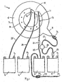
- Figures 1 and 2 show an example of a set of bags adapted to the separation of whole blood into a plasma component (essentially comprising plasma), a platelet component (essentially comprising platelets), a mononuclear cell component (comprising monocytes, lymphocytes and red blood cells) and a red blood cell component (essentially comprising red blood cells and granulocytes).
- This bag set comprises a flexible separation bag 1 and four flexible satellite bags 2, 3, 4, 5 connected thereto.
- the separation bag 1 comprises an annular separation chamber 6 having generally circular outer and inner edges 7, 8. The outer circular edge 7 and the inner circular edge 8 of the separation chamber 6 are substantially concentric.
- the separation chamber 6 comprises a first, acute-angled, funnel-like extension 9 protruding outwardly from its outer edge 7 for helping drain a content of the separation chamber 6 into the fourth satellite bag 5.
- the separation chamber 6 also comprises a second, obtuse-angled, funnel-like extension 10 protruding from the inner edge 8, towards the center of the bag 1, for helping funnel separated components into the first, second and third satellite bags 2, 3, 4.
- the separation bag 1 further comprises a semi-flexible disk-shaped connecting element 11 that is connected to the inner edge 8 of the annular chamber 5.
- the disk-shaped connecting element 11 comprises three rounded recesses 12 on its inner edge facing the second funnel-like extension 10, for partially surrounding three pinch valve members of a rotor of a centrifuge to be described later (diagrammatically shown in doted line in figure 2 ).
- the disk-shaped connecting element 11 comprises a series of holes 13 for connecting the separation bag 1 to the rotor of a centrifuge.
- the first satellite bag 2 has two purposes, and is successively used as a whole blood collection bag and as a mononuclear cell component bag.
- the first satellite bag 2 is intended for initially receiving a volume of whole blood from a donor (usually about 450 ml) before the separation process, and the mononuclear cell component during the separation process.
- the first satellite bag 2 is flat, substantially rectangular, and comprises two reinforced ears at its upper corners having holes 14 for hanging the bag. It is connected to the separation bag 1 by a first transfer tube 20 having a first end connected to the upper edge of the first satellite bag 2 and a second end connected to the second funnel-like extension 10, close to the inner circular edge 8.
- the first satellite bag 2 contains a volume of anti-coagulant solution (typically about 63 ml of a solution of citrate phosphate dextrose for a blood donation of about 450 ml).
- a frangible connector 21 mounted on the transfer tube 20 blocks a liquid flow through the first transfer tube 20 and prevents the anti-coagulant solution from flowing from the first satellite bag 2 into the separation bag 1.
- the bag set further comprises a collection tube 22 that is connected at one end to the upper edge of the first satellite bag 2 and comprises, at the other end, a needle protected by a sheath 23.
- the collection tube 22 is fitted with a clamp 24.
- the second satellite bag 3 is intended for receiving a plasma component
- the second satellite bag 3 is flat, substantially rectangular, and comprises two reinforced ears at its upper corners having holes 14 for hanging the bag. It is connected by a second transfer tube 25 to the separation bag 1.
- the second transfer tube 25 has a first end connected to the upper edge of the second satellite bag 3 and a second end connected to the second funnel-like extension 10, close to the inner circular edge 8, opposite the second end of the first transfer tube 20 with respect to the tip of the second funnel-like extension 10.
- the third satellite bag 4 is intended for receiving a platelet component. It is flat, substantially rectangular, and comprises two reinforced ears at its upper corners having holes 14 for hanging the bag. It is connected by a third transfer tube 26 to the separation bag 1.
- the third transfer tube 26 has a first end connected to the upper edge of the third satellite bag 4 and a second end connected to the tip of the second funnel-like extension 10.
- the fourth satellite bag 5 is intended for receiving a red blood cell component. It is flat, substantially rectangular, and comprises two reinforced ears at its upper corners having holes 14 for hanging the bag. It is connected by a fourth transfer tube 27 to the separation bag 1.
- the fourth transfer tube 27 has a first end connected to the upper edge of the fourth satellite bag 5 and a second end connected to the tip of the first funnel-like extension 9. It comprises two tube segments respectively connected to the inlet and the outlet of a leuko-reduction filter 28.
- the tube segment connected to the separation bag 1 is fitted with a clamp 24.
- the tube segment connected to the fourth satellite bag 5 is fitted with a frangible connector 29, which, when broken, allows a flow of liquid between the separation bag 1 and the fourth satellite bag 5.
- the fitter may be, for example, a filter of the type RC2D manufactured by Pall Corporation.
- a filter comprises a disk-shaped casing to which radial inlet and outlet ports are connected, in diametral opposition.
- the casing which is made of polycarbonate (GE Lexan HF 1140), has an internal volume of about 33 ml. It is filled with a filtering medium composed of multiple layers of a non-woven web of polyester fibers (about two micron diameter).
- the third satellite bag 4 contains a volume of storage solution for red blood cells.
- Variants of the separation bag 1 may include a separation chamber 6 having an outer circular edge 7 and/or an inner circular edge 8 that are eccentric; a separation chamber 6 comprising a radial wall extending from the inner edge 8 to the outer edge 7 so that the chamber 6, instead of being annular, is C-shaped.
- a separation chamber 6 having any shape including an inner edge and an outer edge (the inner edge being closer to the axis of the rotor of a centrifuge than the outer edge, when the separation bag is mounted on the rotor of a centrifuge), for example the shape of a portion of annulus delimited by.two lateral radial edge or a rectangular shape.
- all the satellite bags may be connected to the inner edge of the separation bag.
- the separation bag 1 can be shaped so as to fit either on a flat support surface or on a frusto-conical support surface of the rotor of a centrifuge.
- the bags and the tubes of the bag set shown in figures 1 and 2 are all made of flexible plastic material appropriate to contact blood and blood components.
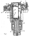
- FIGs 3 and 4 show an embodiment of an apparatus for separating a volume of composite liquid by centrifugation.
- the apparatus comprises a centrifuge adapted for receiving the set of separation bags shown in figures 1 and 2 , and a component transferring means for causing the transfer of separated components into the satellite bags.
- the centrifuge comprises a rotor that is supported by a bearing assembly 30 allowing the rotor to rotate about a vertical central axis 31.
- the rotor comprises a cylindrical rotor shaft comprising a first upper portion 32 and a second lower portion 33; the upper portion 32 of the shaft extends in part through the bearing assembly 30; a pulley 34 is connected to the lower end of the upper portion 32 of the shaft; a central compartment 35 for containing satellite bags, which is connected to the rotor shaft 32, 33 at the upper end thereof; a support member 36 fitting within the central compartment 34, for supporting at least one satellite bag in a determined position within the central compartment 35; a circular turntable 37 for supporting a separation bag, which is connected to the compartment 35 at the upper end thereof, the central axes of the rotor shaft 32, 33, the compartment 35 and the turntable 37 coinciding with the rotation axis 31; and a balancing assembly 38, which is secured to the turntable 37.
- the centrifuge further comprises a motor 40 coupled to the rotor by a belt 41 engaged in a groove of the pulley 34 so as to rotate the rotor about the central vertical axis 31.
- the separation apparatus further comprises a first, second and third pinch valve members 42, 43, 44 that are mounted on the rotor for selectively blocking or allowing a flow of liquid through a flexible plastic tube, and selectively sealing and cutting a plastic tube.
- Each pinch valve member 42, 43, 44 comprises an elongated cylindrical body and a head having a groove that is defined by a stationary upper jaw and a lower jaw movable between an open and a closed position, the groove being dimensioned so that one of the transfer tubes 20, 25, 26 of the bag sets shown in figures 1 and 2 can be snuggly engaged therein when the lower jaw is in the open position.
- the elongated body contains a mechanism for moving the lower jaw and it is connected to a radio frequency generator that supplies the energy necessary for sealing and cutting a plastic tube.
- the pinch valve members 42, 43, 44 are mounted at the periphery of the central compartment 34 so that their longitudinal axes are coplanar, and parallel to the central axis 31 of the rotor, and their heads protrude above the rim of the central compartment 35.
- the position of the pinch valve members 42, 43, 44 with respect to the separation bag 1 and the transfer tubes 20, 25, 26 connected thereto when the separation bag 1 is mounted on the turntable 37 is shown in doted lines in figure 2 . Electric power is supplied to the pinch valve members 42, 43, 44 through a slip ring array 45 that is mounted around the lower portion 33 of the rotor shaft.
- the support member 36 generally comprises a portion of wall 46 that is tilted with respect to the rotation axis 31 of the rotor.
- a satellite bag secured by an upper portion thereof to an upper part of the tilted wall 46 is pressed against the tilted wall 46 by centrifugation forces during rotation of the rotor and a lower portion of the, satellite bag is closer to the axis of rotation than an upper portion thereof.
- a liquid contained in the supported satellite bag drains from the supported satellite bag into the separation bag under centrifugation forces.
- the turntable 37 comprises a central frusto-conical portion 47, the upper, smaller edge of which is connected to the rim of the compartment 34, an annular flat portion 48 connected to the lower, larger edge of the frusto-conical portion 47, and an outer cylindrical flange 49 extending upwards from the outer periphery of the annular portion 48.
- the turntable 35 further comprises a vaulted circular lid 50 that is secured to the flange 49 by a hinge so as to pivot between an open and a closed position.
- the lid 50 is fitted with a lock 51 by which it can be blocked in the closed position.
- the lid 50 has an annular interior surface that is so shaped that, when the lid 50 is in the closed position, it defines with the frusto-conical portion 47 and the annular flat portion 48 of the turntable 37, a frusto-conical annular compartment 52 having a radial cross-section that has substantially the shape of a parallelogram.
- the frusto-conical annular compartment 52 (later the "separation compartment"), which has a fixed volume, is intended for containing the separation bag 1 shown in figures 1 and 2 .
- the balancing assembly 38 which has generally the shape of a ring, is mounted on the rotor within the space that extends between the upper end of the central compartment 35 and the frusto-conical wall 47 of the turntable 37.
- the balancing assembly 38 comprises a ring-shaped housing 53 defining a cavity whose cross-section, along a radial plane, is generally rectangular.
- the balancing assembly further comprises a plurality of ponderous balls 54 having a diameter that is slightly less than the radial depth of the cavity of the housing 53. When the balls 54 are in contact with each other they occupy a sector of the housing 52 of about 180 degrees.
- the component transferring means comprises a squeezing system for squeezing the separation bag within the separation compartment 52 and causing the transfer of separated components into the satellite bags.
- the squeezing system comprises a flexible annular diaphragm 55 that is so shaped as to line the frusto-conical portion 47 and the annular flat portion 48 of the turntable 37, to which it is secured along its smaller and larger circular edges.
- the squeezing system further comprises a hydraulic pumping station 60 for pumping a hydraulic liquid in and out an expandable hydraulic chamber 56 defined between the flexible diaphragm 55 and the turntable 37, via a duct 57 extending through the rotor from the lower end of the lower portion 33 of the rotor shaft to the turntable 37.
- the pumping station 60 comprises a piston pump having a piston 61 movable in a hydraulic cylinder 62 fluidly connected via a rotary fluid coupling 58 to the rotor duct 57.
- the piston 61 is actuated by a stepper motor 63 that moves a lead screw 64 linked to the piston rod 62.
- the stepper motor 63 can be controlled by discrete increments or steps, each step corresponding to a fraction of a turn of the axle of the motor 63; that is, also to a small linear displacement of the piston 61; that is also to a small determined volume of liquid being pumped in or out of the hydraulic chamber 56.
- the hydraulic cylinder 62 is also connected to a hydraulic liquid reservoir 65 having an access controlled by a valve 66 for selectively allowing the introduction or the withdrawal of hydraulic liquid into and from a hydraulic circuit including the hydraulic cylinder 62, the rotor duct 57 and the expandable hydraulic chamber 56.
- a pressure gauge 67 is connected to the hydraulic circuit for measuring the hydraulic pressure therein.
- the separation apparatus further comprises three sensors 70, 71, 72 for detecting characteristics of the separation process occurring within a separation bag 1 when the apparatus operates.
- the three sensors 70, 71, 72 are embedded in the lid 50 at different distances from the rotation axis 31 of the rotor, a first sensor 70 being the closest to the rotation axis 31, a second sensor 71 being the farthest to the rotation axis 31 and a third sensor 72 occupying an intermediate position.
- the three sensors 70, 71, 72 face the separation bag 1 as shown in figure 2 .
- the first sensor 70 (later the "inner sensor”) is embedded in the lid 50 so as to be positioned over the separation chamber 6 at a short distance from the end of the second transfer tube 25 connected to the second funnel-like extension 10 (plasma outlet).
- the inner sensor 70 is able to detect an interface gas/liquid, an interface between plasma and a platelet/mononuclear cell layer, an interface between platelet rich plasma and mononuclear cells, as well as red blood cells.
- the second sensor 71 (later the "outer sensor”) is embedded in the lid 50 so as to be positioned over the separation chamber 6 at about two third of the width of the separation chamber from the inner edge 8 thereof, and it is offset with respect to the second funnel-like extension 10, while being closer to the end of the second transfer tube 25 than to the respective ends of the first and second transfer tubes 20, 26.
- the outer sensor 71 is able to detect a liquid, e.g. blood.
- the third sensor 72 (later the "intermediate sensor”) is embedded in the lid 50 so as to be positioned over the separation chamber 6 at about one third of the width of the separation chamber from the inner edge 8 thereof, substantially on the same radius as the end of the third transfer tube 26 (platelet outlet) connected to the second funnel-like extension 10.
- the intermediate sensor 72 is able to detect an interface between plasma and blood cells.
- Each sensor 70, 71, 72 can comprise a photocell including an infra-red LED and a photo-detector. Electric power is supplied to the sensors 70, 71, 72 through the slip ring array 45.
- the separation apparatus further comprises a controller 80 including a control unit (microprocessor) and a memory for providing the microprocessor with information and programmed instructions relative to various separation protocols and to the operation of the apparatus in accordance with such separation protocols.
- the microprocessor is programmed for receiving information relative to the centrifugation speed(s) at which the rotor is to be rotated during the various stages of a separation process, and information relative to the various transfer flow rates at which separated components are to be transferred from the separation bag 1 into the satellite bags 2, 3, 4.
- the information relative to the various transfer flow rates can be expressed, for example, as hydraulic liquid flow rates in the hydraulic circuit, or as rotation speeds of the stepper motor 63 of the hydraulic pumping station 60.
- the microprocessor is further programmed for receiving, directly or through the memory, information from the pressure gauge 67 and from the photocells 70, 71, 72 and for controlling the centrifuge motor 40, the stepper motor 63, and the pinch valve members 42, 43, 44 so as to cause the separation apparatus to operate along a selected separation protocol.
- the control unit 80 is also programmed for determining and displaying on a screen 81 of the separation apparatus the actual volume of the components separated during a separation procedure, as well as the actual volume of the composite liquid (whole blood) initially contained in the separation bag 1.
- a first separation protocol aiming at the preparation of four blood components from a whole blood donation, namely a plasma component, a platelet component, a mononuclear cell component and a red blood cell component, is explained below.
- the operation of the separation apparatus along the first separation protocol is as follows.
- a bag set as shown in figure 1 in which the satellite bag 2 contains a volume of whole blood, is set in place in the rotor of a centrifuge (as shown in figures 3 , 4 ).
- the first satellite bag 2 of the bag set of figure 1 contains a volume of anti-coagulated whole blood (usually about 500 ml).
- the collection tube 22 has been sealed and cut close to the first satellite bag 2.
- the clamp 24 on the transfer tube 27 connecting the fourth satellite bag 5 to the separation bag 1 is closed.
- the four satellite bags 2, 3, 4, 5 are superposed one upon another so as to form a stack that is inserted in the bag loader 36 so that the first satellite bag 2 is adjacent the tilted wall 46 of the bag loader 36.
- the satellite bags 2, 3, 4, 5 are secured by their upper ears to an upper part of the bag loader 36, above the tilted wall 46. In this position, they are substantially located on one side of a plane containing the rotation axis 31 of the rotor, and a lower portion of the first satellite bag 2 containing the volume of whole blood is closer to the rotation axis 31 than an upper portion thereof.
- the collection bag 1 is then laid on the turntable 37 and pins (not shown) protruding on the turntable 37 around the opening of the central compartment 35 are engaged in the holes 13 of the disk-shaped connecting element 11 of the separation bag 1.
- the first transfer tube 20 connecting the first satellite bag 2 to the separation bag 1 is engaged in the first pinch valve member 42
- the second transfer tube 25 connecting the second satellite bag 3 to the separation bag 1 is engaged in the second pinch valve member 43
- the third transfer tube 26 connecting the third satellite bag 4 to the separation bag 1 is engaged in the third pinch valve member 44.
- the frangible connector 21 blocking communication between the first satellite bag 2 and the separation bag 1 is broken.
- the lid 49 of the rotor is closed.
- the anti-coagulated whole blood contained in the first satellite bag 2 is transferred into the separation bag 1.
- the first pinch valve member 42 is open and the second and third pinch valve members 43, 44 are closed.
- the rotor is set in motion by the centrifuge motor 40 and its rotation speed increases steadily until it reaches a first centrifugation speed (e.g.
- the pressure threshold above which hemolysis occurs in the satellite bag 2 is about 10 PSI, and that the maximum rotation speed at which such pressure threshold is not reached and the shearing forces in the blood flow entering the separation bag do not cause hemolysis is about 1800 RPM. At a rotation speed of about 1500 RPM, it takes about one minute for transferring about 500ml of anti-coagulated blood from the satellite bag 2 into the separation bag 1.
- the valve member 43 controlling a flow of fluid through the second transfer tube 25 connected to the second satellite bag 3 (in which a plasma component will be later transferred) is opened for a predetermined amount of time (for example, about 30 seconds) so as to allow air to vent from the separation bag 1 when blood pours therein.
- control unit 80 causes the rotor to stop and an alarm to be emitted. This could happen in particular if the frangible connector 21 has inadvertently not been broken.
- the air present in the separation bag 1 is purged into the first satellite bag 2, in which the mononuclear cell component is to be later transferred.
- the whole content of the first satellite bag 2 has been transferred into the separation bag 1, the first pinch valve member 42 is open, and the second and third pinch valve members 43, 44 are closed.
- the rotor rotates at the first rotation speed (about 1500 RPM).
- the pumping station 60 is actuated so as to pump hydraulic liquid at a constant flow rate (for example, about 240m/min) into the hydraulic chamber 56 and consequently squeeze the separation bag 1.
- the air present in the separation bag 1 is expelled into the first satellite bag 2 for the mononuclear cell component
- the pumping station 60 is stopped and the first pinch valve member 42 is closed. A small residual volume of air remains in the separation bag 1.
- the blood within the separation chamber is sedimented to a desired level.
- the three pinch valve members 42, 43, 44 are closed.
- the speed of the rotor is increased steadily until it reaches a second, high, centrifugation speed (for example, about 3200 RPM, so-called "hard spin") at which the blood components will sediment at the desired level.
- the rotor is rotated at the second centrifugation speed for a predetermined period of time (for example, about 220 seconds), which is selected so that, whatever the hematocrit of the whole blood initially transferred in the separation chamber 1, the blood sediments therein at the end of the predetermined period to a point where the hematocrit of the outer annular red blood cell layer is about 90 and the inner annular plasma layer is substantially devoid of cells.
- the separation bag 1 exhibits four layers: a first inner layer mainly comprising plasma, a second intermediate layer mainly comprising platelets, a third intermediate layer mainly comprising white blood cells (lymphocytes, monocytes and granulocytes), and a fourth outer layer mainly comprising red blood cells, wherein the third and fourth layers partially overlap (the granulocytes are in part embedded in the fourth layer).
- a plasma component is transferred into the second satellite bag 3.
- the three pinch valve members 42, 43, 44 are closed.
- the rotor is rotated at the same high centrifugation speed as in the sedimentation stage.
- the second pinch valve member 43 controlling the access to the second satellite bag 3 is opened and the pumping station 60 is actuated so as to pump hydraulic liquid at a constant flow rate (for example, about 220 ml/min) into the hydraulic chamber 56.
- the expanding hydraulic chamber 56 squeezes the separation bag 1 and causes the transfer of the residual volume of air and plasma into the second satellite bag 3.
- the pumping station 60 is stopped and the second pinch valve member 43 is closed after a predetermined period of time has elapsed following the detection of the inward moving plasma/blood cell interface by the intermediate sensor 72.
- a first, larger, fraction of the total volume of plasma is in the second satellite bag 3, whereas a second, smaller, fraction of the total volume of plasma remains in the separation bag 1.
- the transfer flow rate of the plasma component (which is directly related to the flow rate of the hydraulic fluid) is selected to be as high as possible without disturbing the platelet layer so as to avoid contaminating the plasma component with platelets.
- the control unit 80 determines the volume of plasma that has been transferred into the second satellite bag 3 as follows. First, it determines when plasma actually starts pouring into the second satellite bag 3, after the residual amount of air present in the separation bag has been evacuated in the second satellite bag 3. Second, it counts the number of steps performed by the stepper motor 63 between the time plasma actually starts pouring into the second satellite bag 3, and the time the pumping station 60 stops pumping hydraulic liquid into the hydraulic chamber 56 after the intermediate sensor 72 has detected an interface plasma/blood cells. Finally, the control unit 80 calculates, from the counted number of steps and the determined small volume associated to one step, the total volume of hydraulic liquid pumped into the hydraulic chamber 56 during this stage, which corresponds to the volume of plasma in the second satellite bag 3.
- the control unit 80 determines when plasma actually starts pouring into the second satellite bag 3 by continuously recording discrete successive values of the pressure of the hydraulic liquid as measured by the pressure sensor 67, and simultaneously analyzing how the pressure evolves, for example by calculating, each time a new pressure value is recorded, from the average of the last four measured values the slope of a curve representing the evolution of the pressure with respect to time, and by comparing the series of slopes so calculated.
- the control unit 80 determines the point in time at which plasma start pouring into the second satellite bag as corresponding to a drastic turning point between a first phase of steadily increasing pressure and a second phase of substantially constant pressure.
- the control unit 80 can be programmed to cause the actual volume of plasma in the second satellite bag 3, once determined, to be displayed on the screen 81.
- the control unit 80 also determines the volume of anti-coagulated whole blood that has been transferred into the separation bag 1 during the third stage, first, by counting the number of steps performed by the stepper motor 63 between the time the pumping station 60 starts pumping hydraulic fluid into the hydraulic chamber 56 at the third stage (transfer of air into the first satellite bag 2), and the time when plasma actually starts pouring into the second satellite bag 3, as determined above; and second, by the control unit 80 calculating from the counted number of steps and the determined small volume associated to one step, the total volume of hydraulic liquid pumped into the hydraulic chamber 56 until the separation compartment 52 does not contain air anymore; and finally, by the control unit 80 calculating the volume of anti-coagulated blood that is in the separation chamber 1, by subtracting the volume of hydraulic liquid so calculated from a fixed volume, stored in the memory of the control units 80.
- This fixed volume corresponds to the fixed volume of the separation compartment 52, minus the volume of the diaphragm 55, minus the volume of the two superposed rings of plastic sheets delimiting the separation chamber 6, and minus a fixed residual volume of hydraulic liquid in the hydraulic chamber 56.
- the control unit 80 can be programmed to cause the actual volume of anti-coagulated blood in the separation bag 1, once determined, to be displayed on the screen 81.
- a platelet component is prepared in the separation bag 1.
- the third pinch valve member 44 controlling access to the third satellite bag 4 is open, and the first and second pinch valve members 42, 43 are closed.
- the rotation speed of the rotor is rapidly decreased from the second centrifugation speed to a third centrifugation speed (for example, from about 3200 RPM to about 2000 RPM, within about 10 seconds) so as to form an intermediate component resulting from the suspension of the platelets into the second fraction of the plasma, whereas the red blood cell layer and the suspended platelet layer remains substantially separated.
- the three pinch valve members 42, 43, 44 are closed.
- the rotation speed of the rotor is rapidly decreased from the second centrifugation speed to a third centrifugation speed (for example, from about 3200 RPM to about 1000 RPM, within about 20 seconds) so as to mix red blood cells, the platelets and the second portion of the plasma.
- the rotation speed of the rotor is then increased from the third centrifugation speed to a fourth centrifugation speed, lower that the first centrifugation speed (for example, from about 1000 RPM to about 2500 RPM), so as to separate in the separation bag 1 a red blood cell component and a platelet component comprising a suspension of platelets in plasma.
- the platelet component is transferred into the fourth satellite bag 3.
- the third pinch valve member 44 controlling the access to the third satellite bag 4 is open and the first and second pinch valve members 42, 43 are closed.
- the rotor is rotated at the third centrifugation speed (for example, about 2000 RPM, if the preceding stage is the first variant of the sixth stage) or at the fourth rotation speed (for example, about 2500 RPM, if the preceding stage is the second variant of the sixth stage).
- the pumping station 60 is actuated so as to pump hydraulic liquid at a first flow rate into the hydraulic chamber 56 and consequently squeeze the separation bag 1 and cause the transfer of the platelet component into the third satellite bag 4.
- the first flow rate (for example, about 140 ml/min) is substantially lower than the flow rate (for example, about 220 ml/min) at which the plasma component is transferred into the second satellite bag 3 in the fifth stage.
- the first transfer flow rate of the platelet component (which is directly related to the first flow rate of the hydraulic fluid), is selected to be high enough for preventing the suspended platelets from sedimenting, without, at the same time, triggering the activation of the platelets.
- the pumping station 60 When the inner sensor 70 detects an interface between the suspended platelets and mononuclear/red blood cells, the pumping station 60 is actuated so as to pump hydraulic liquid into the hydraulic chamber 56 at a second flow rate, (for example 40 ml/min), that is substantially lower than the first flow rate, in order to prevent the contamination of the platelet component by mononuclear/red blood cells.
- a second flow rate for example 40 ml/min
- the pumping station 60 When a predetermined volume of hydraulic liquid has been pumped into the hydraulic chamber 56 at the second flow rate, the pumping station 60 is actuated so as to pump hydraulic liquid at a third flow rate, (for example, about 20 ml/min), that is lower than the second flow rate. When a predetermined volume of hydraulic liquid has been pumped into the hydraulic chamber 56 at the third flow rate, the pumping station 60 is stopped.
- a third flow rate for example, about 20 ml/min
- the control unit 80 determines the volume of the platelet component that has been transferred into the third satellite bag in the following manner it first counts the number of steps performed by the stepper motor 63 between the time the pumping station 60 starts pumping hydraulic fluid into the hydraulic chamber 56 following the opening of the third pinch valve member 44, and the time the pumping station 60 stops doing so after the inner sensor 70 has detected the interface between the suspended platelets and the mononuclear/red blood cells; second, the control unit 80 calculates, from the counted number of steps and the determined small volume associated to one step, the total volume of hydraulic liquid pumped into the hydraulic chamber 56 during this stage, which corresponds to the volume of the platelet component in the third satellite bag 4.
- the control unit 80 can be programmed to cause the actual volume of the platelet component in the third satellite bag 4, once determined, to be displayed on the screen 81.
- a mononuclear cell component is transferred into the first satellite bag 2.
- the eighth stage can start as soon as the third pinch valve member44 is closed at the end of the seventh stage.
- the three pinch valve members 42, 43, 44 are closed.
- the rotor is rotated at the same centrifugation speed as previously.
- the first pinch valve member 42 controlling the access to the first satellite bag 2 is opened and the pumping system 60 is actuated so as to pump hydraulic liquid at a constant flow rate, (for example, about 140 ml/min), into the hydraulic chamber 56.
- the expanding hydraulic chamber 56 squeezes the separation bag 1 and causes the transfer, into the first satellite bag 2, of a mononuclear cells component comprising lymphocytes; monocytes, a small amount of red blood cells, as well a residual volume of platelet rich plasma.
- the pumping system 60 is stopped arid the first pinch valve member 42 is closed after a predetermined volume, (e.g. between 10 and 15 ml), has been transferred into the first satellite bag 2.
- the control unit 80 determines the actual volume of the mononuclear cell component in the first satellite bag 2 by adding the volume of the mononuclear cell component actually transferred into the first satellite bag 2, which volume corresponds to the number of steps performed by the stepper motor between the opening and the closing of the first pinch valve member 42, to an empirically determined volume of whole blood remaining in the first satellite bag 2, which is stored in the memory of the control unit
- the control unit 80 can be programmed to cause the actual volume of the mononuclear cell component in the first satellite bag 2, once determined, to be displayed on the screen 81.
- the control unit 80 determines the volume of red blood cells remaining in the separation bag 1 by subtracting, from the previously determined volume of anti-coagulated whole blood, the previously determined volumes of plasma component, platelet component, and mononuclear cell component.
- the control unit 80 can also determine the volume of red blood cells in the fourth satellite bag 5, which will result from the actual subsequent transfer of red blood cells from the separation bag 1 into the fourth satellite bag 5 at the outcome of the tenth stage of the first separation protocol.
- the control unit 80 calculates the volume of red blood cells by subtracting, from the previously determined volume of anti-coagulated whole blood, the previously determined volumes of plasma component, platelet component, mononuclear cell component, and the internal volume of the leuko-reduction filter 28, and adding to the result the known volume of red blood cell storage solution contained in the fourth satellite bag 5.
- the control unit 80 can be programmed to cause either one of the actual volume of the red blood cell component in the separation bag 1 and the actual volume of the red blood cell component in the fourth satellite bag 5, or both, once determined, to be displayed on the screen 81.
- the centrifugation process is ended.
- the rotation speed of the rotor is decreased until the rotor stops, the pumping system 60 is actuated so as to pump the hydraulic liquid from the hydraulic chamber 56 at a high flow rate, (for example, about 800 ml/min), until the hydraulic chamber 56 is substantially empty, and the pinch valve members 42, 43, 44 are actuated so as to seal and cut the transfer tubes 20, 25, 26. Red blood cells remain in the separation bag 1.
- a high flow rate for example, about 800 ml/min
- a red blood cell component is transferred into the fourth satellite bag 5.
- the lid 50 of the rotor is opened and the separation bag 1 connected to the fourth satellite bag 5 is removed therefrom.
- the clamp 24 on the transfer tube 27 is opened.
- the frangible connector 29 blocking communication between the fourth satellite bag 5 and the leuko-reduction filter 28 is broken.
- the storage solution contained in the fourth satellite bag 5 is allowed to flow by gravity through the filter 28 and into the separation bag 1 where it is mixed with the red blood cells so as to lower the viscosity thereof.
- the content of the separation bag 1 is then allowed to flow by gravity through the filter 28 and into the fourth satellite bag 5.
- the white blood cells (granulocytes and residual monocytes and lymphocytes) are trapped by the filter 28, so that the ultimate packed red blood cell component in the fourth satellite bag 5 is substantially devoid from white blood cells and meets the standard of the AABB (American Association of Blood Banks), which is less than 5 x 10 6 white blood cells per packed red blood cell component.
- AABB American Association of Blood Banks
- the above apparatus can be programmed to carry out other separation protocols, for example for carrying out a second separation protocol for separating three components, namely a plasma component, a "buffy coat” component comprising plasma, platelets, white blood cells and red blood cells, and a red blood cell component, or a third separation protocol for separating two components, namely a platelet rich plasma component and a red blood cell component.
- a second separation protocol for separating three components, namely a plasma component, a "buffy coat" component comprising plasma, platelets, white blood cells and red blood cells, and a red blood cell component
- a third separation protocol for separating two components, namely a platelet rich plasma component and a red blood cell component.
- a set of bags as shown in figure 1 without a third satellite bag (for platelets), is used for carrying out the second protocol.
- the main steps of the second protocol are as follows: the whole blood is transferred from the first satellite bag 2 into the separation bag 1; after a hard spin sedimentation step (3200 RPM), most of the plasma is transferred into the second satellite bag 3 and a "buffy coat" component of predetermined volume is transferred into the first satellite bag 2; and the red blood cells are transferred by gravity into a red blood cell satellite bag 5.
- the control unit 80 determines the volume of anti-coagulated whole blood, of the plasma component, the "buffy coat” component, and a red blood cell component as explained above with respect to the first protocol, (the "buffy coat” component corresponding to the mononuclear cell component).
- a set of bags as shown in figure 1 without a third satellite bag (for platelets), is used for carrying out the third protocol.
- the main steps of the third protocol are as follows: the whole blood is transferred into the separation bag 1 from the first satellite bag 2 (which is not re-used later); after a soft spin sedimentation step (2000 RPM), a platelet rich plasma component is transferred into the second satellite bag 3; and the red blood cells are finally transferred by gravity into a red blood cell satellite bag 5.
- the control unit 80 determines the volume of anti-coagulated whole blood, of the platelet rich plasma component, and of the red blood cell component as explained above with respect to the first protocol, (the platelet rich plasma component corresponding to the plasma component).
- the various actual volume values determined by the control unit 80 can be selectively displayed on the screen 81 of the separation apparatus. They are also stored in the memory of the control unit to be later printed on the satellite bags. This data can also be transferred to a database collecting separation data from multiple separation apparatuses and protocols so as to serve for statistical analyses.
Claims (12)
- Dispositif pour séparer un volume de liquide composite en au moins un premier constituant et un deuxième constituant dans une poche de séparation (1), comprenant :un rotor pour faire tourner la poche de séparation (1) autour d'un axe de rotation du rotor ;un système de transfert de fluide pour provoquer un transfert de gaz et au moins une première fraction d'un premier constituant de la poche de séparation (1) dans une poche de premier constituant (3) y étant raccordée ;une mémoire pour stocker au moins une vitesse de centrifugation du rotor permettant la sédimentation d'au moins un premier constituant et un deuxième constituant d'un volume de liquide composite contenu dans une poche de séparation (1) ;etune unité de commande (80) programmée pour :amener le rotor à effectuer une rotation à l'au moins une vitesse de centrifugation du rotor afin de provoquer la sédimentation d'au un moins premier et un deuxième constituants d'un volume de liquide composite contenu dans une poche de séparation (1) ;amener le système de transfert de fluide à transférer du gaz et au moins une fraction du premier constituant dans une poche de premier constituant (3) raccordée à la poche de séparation (1) ; etdéterminer un volume effectif de l'au moins une fraction du premier constituant transféré dans une poche de premier constituant (3) entre le début de l'écoulement du premier constituant dans la poche de premier constituant et l'arrêt de l'écoulement du premier constituant dans la poche de premier constituant (3) ;où le rotor comprend en outre un compartiment de séparation (52) destiné à contenir la poche de séparation (1) ;où le système de transfert de fluide comprend un moyen de pompage pour pomper un liquide hydraulique, par incréments d'un volume discret déterminé, dans le compartiment de séparation (52) du rotor destiné à contenir la poche de séparation (1), etoù l'unité de commande (80) est en outre programmée pour :compter le nombre d'incréments entre le début de l'écoulement du premier constituant dans la poche de premier constituant (3) et l'arrêt de l'écoulement du premier constituant dans la poche de premier constituant (3) ; etdéterminer le volume effectif de la première fraction du premier constituant transféré dans la poche de premier constituant (3) à partir du nombre d'incréments comptés et du volume déterminé correspondant à un incrément.
- Dispositif selon la revendication 1, où le système de transfert de fluide comprend :un système de compression pour appliquer une pression sur la poche de séparation (1) ; etun capteur de pression (67) pour mesurer une pression appliquée à la poche de séparation (1), où l'unité de commande (80) est en outre programmée pour :recevoir des informations du capteur de pression (67) ;surveiller les informations de pression du capteur de pression (67) afin de déterminer le moment où le premier constituant commence à s'écouler dans la poche de premier constituant (3) après transfert d'un volume de gaz dans celle-ci.
- Dispositif selon la revendication 2, où l'unité de commande (80) et en outre programmée pour déterminer le moment où le premier constituant commence effectivement à s'écouler dans la poche de premier constituant (3) en détectant un changement de pression correspondant à la pression devenant sensiblement constante après avoir augmenté sensiblement et régulièrement lors du transfert du volume de gaz.
- Dispositif selon la revendication 1, comprenant en outre un détecteur d'interface (72) destiné à détecter une interface entre les premier et deuxième constituants dans la poche de séparation à une distance de l'axe de rotation, où l'unité de commande est en outre programmée pour :recevoir des informations du détecteur d'interface (72) ; etamener le système de transfert de fluide à interrompre le transfert de la première fraction du premier constituant dans la poche de premier constituant (3) après détection de l'interface entre les premier et deuxième constituants par le détecteur d'interface (72).
- Dispositif selon la revendication 1, comprenant en outre un détecteur d'interface (70) destiné à détecter une interface entre du gaz et le liquide composite dans la poche de séparation à une distance de l'axe de rotation, où l'unité de commande est en outre programmée pour :recevoir des informations du détecteur d'interface (70) ; etamener le système de transfert de fluide à transférer du gaz de la poche de séparation dans une poche satellite raccordée à celle-ci jusqu'à l'expiration d'une durée déterminée après détection d'une interface entre du gaz et le liquide composite par le détecteur d'interface (70).
- Dispositif selon la revendication 1, où l'unité de commande (80) est en outre programmée pour :pomper un fluide hydraulique dans le compartiment de séparation (52) afin de provoquer le transfert d'un volume de gaz contenu dans la poche de séparation (1) dans au moins une poche de constituant et le transfert de la première fraction du premier constituant dans la poche de premier constituant (3) ;déterminer un volume de liquide hydraulique pompé dans le compartiment de séparation (52) jusqu'à ce que le premier constituant commence à s'écouler dans la poche de premier constituant (3) ; etdéterminer le volume effectif de liquide composite dans la poche de séparation (1) à partir d'au moins le volume fixe du compartiment de séparation (52), et le volume de fluide hydraulique pompé dans le compartiment de séparation (52) jusqu'à ce que le premier constituant commence à s'écouler dans la poche de premier constituant (3).
- Dispositif selon la revendication 6, où l'unité de commande (80) est en outre programmée pour :compter le nombre d'incréments entre le début de l'écoulement du fluide hydraulique dans le compartiment de séparation (52) et le début de l'écoulement du premier constituant dans la poche de premier constituant (3) ;calculer le volume de fluide hydraulique pompé dans le compartiment de séparation (52) à partir du nombre d'incréments comptés et du volume discret déterminé d'un incrément.
- Dispositif selon la revendication 7, où l'unité de commande (80) est en outre programmée pour déterminer un volume effectif du deuxième constituant à partir d'au moins le volume effectif déterminé du liquide composite dans la poche de séparation (1), et le volume effectif du premier constituant transféré dans la poche de premier constituant (3).
- Dispositif selon la revendication 1, où :au moins une vitesse de centrifugation de rotor stockée dans la mémoire permet la sédimentation d'au moins un premier constituant, un deuxième constituant et un constituant intermédiaire d'un volume de liquide composite contenu dans la poche de séparation ; etl'unité de commande (80) est en outre programmée pour :amener le rotor à effectuer une rotation à l'au moins une vitesse de centrifugation permettant la sédimentation des premier et deuxième constituants et d'un constituant intermédiaire d'un volume de liquide composite contenu dans une poche de séparation (1) ;amener le système de transfert de fluide à transférer un volume d'un troisième constituant dans une poche de troisième constituant (4) raccordée à la poche de séparation (1), après transfert de la première fraction du premier constituant dans la poche de premier constituant (3), où le troisième constituant comprend une fraction du deuxième constituant, du constituant intermédiaire et une seconde fraction du premier constituant restant dans la poche de séparation (1) après transfert de la première fraction du premier constituant dans la poche de premier constituant (3) ; etdéterminer un volume effectif du troisième constituant transféré dans la poche de troisième constituant (3).
- Dispositif selon la revendication 9, où l'unité de commande (80) est en outre programmée pour :compter le nombre d'incréments entre l'actionnement du système de pompage pour transférer le troisième constituant dans la poche de troisième constituant (4) et l'arrêt du système de pompage ; etdéterminer le volume effectif du troisième constituant transféré dans la poche de troisième constituant (4) à partir du nombre d'incréments comptés et du volume déterminé d'un incrément.
- Dispositif selon la revendication 10, où l'unité de commande (80) est en outre programmée pour déterminer un volume effectif du deuxième constituant à partir d'au moins un volume effectif du liquide composite, le volume effectif déterminé du premier constituant transféré dans la poche de premier constituant (3), et le volume effectif déterminé du troisième constituant transféré dans la poche de troisième constituant (4).
- Dispositif selon la revendication 9, comprenant en outre un écran connecté à l'unité de commande, où l'unité de commande (80) est en outre programmée pour afficher sur l'écran au moins l'un parmi le volume effectif de liquide composite dans la poche de séparation (1), le volume effectif du deuxième constituant dans la poche de séparation (1), le volume effectif de l'au moins une fraction du premier constituant transféré dans la poche de premier constituant (3) et le volume effectif du troisième constituant transféré dans la poche de troisième constituant (4).
Applications Claiming Priority (2)
| Application Number | Priority Date | Filing Date | Title |
|---|---|---|---|
| US82464306P | 2006-09-06 | 2006-09-06 | |
| EP07841463.8A EP2059281B1 (fr) | 2006-09-06 | 2007-08-28 | Procédé pour séparer un liquide composite en au moins deux composants |
Related Parent Applications (3)
| Application Number | Title | Priority Date | Filing Date |
|---|---|---|---|
| EP07841463.8 Division | 2007-08-28 | ||
| EP07841463.8A Division-Into EP2059281B1 (fr) | 2006-09-06 | 2007-08-28 | Procédé pour séparer un liquide composite en au moins deux composants |
| EP07841463.8A Division EP2059281B1 (fr) | 2006-09-06 | 2007-08-28 | Procédé pour séparer un liquide composite en au moins deux composants |
Publications (3)
| Publication Number | Publication Date |
|---|---|
| EP2206527A2 EP2206527A2 (fr) | 2010-07-14 |
| EP2206527A3 EP2206527A3 (fr) | 2012-08-15 |
| EP2206527B1 true EP2206527B1 (fr) | 2016-01-27 |
Family
ID=38904745
Family Applications (2)
| Application Number | Title | Priority Date | Filing Date |
|---|---|---|---|
| EP10003383.6A Active EP2206527B1 (fr) | 2006-09-06 | 2007-08-28 | Appareil et procédé de séparation d'un liquide composite dans au moins deux composants |
| EP07841463.8A Active EP2059281B1 (fr) | 2006-09-06 | 2007-08-28 | Procédé pour séparer un liquide composite en au moins deux composants |
Family Applications After (1)
| Application Number | Title | Priority Date | Filing Date |
|---|---|---|---|
| EP07841463.8A Active EP2059281B1 (fr) | 2006-09-06 | 2007-08-28 | Procédé pour séparer un liquide composite en au moins deux composants |
Country Status (7)
| Country | Link |
|---|---|
| US (1) | US8173027B2 (fr) |
| EP (2) | EP2206527B1 (fr) |
| JP (2) | JP5259595B2 (fr) |
| CN (2) | CN101511406B (fr) |
| AU (1) | AU2007292504A1 (fr) |
| CA (1) | CA2661027A1 (fr) |
| WO (1) | WO2008030731A2 (fr) |
Families Citing this family (21)
| Publication number | Priority date | Publication date | Assignee | Title |
|---|---|---|---|---|
| EP2080531B1 (fr) | 2004-12-28 | 2015-09-02 | Terumo BCT, Inc. | Appareil et procédé de séparation d'un volume de sang total dans au moins trois composants |
| WO2007024518A2 (fr) * | 2005-08-22 | 2007-03-01 | Gambro Inc. | Dispositif et procede permettant de separer un liquide composite en au moins deux composants |
| JP5405313B2 (ja) * | 2006-12-20 | 2014-02-05 | テルモ ビーシーティー、インコーポレーテッド | 複合液体を少なくとも2つの成分に分離するための機器および方法 |
| WO2010014330A2 (fr) * | 2008-07-31 | 2010-02-04 | Caridianbct, Inc. | Procédé et appareil permettant de déterminer le rendement en au moins un composant |
| US20110238029A1 (en) * | 2008-11-28 | 2011-09-29 | Terumo Kabushiki Kaisha | Blood bag system and cassette |
| US20110136650A1 (en) * | 2009-12-08 | 2011-06-09 | Caridianbct, Inc. | Multi-Unit Blood Processor With Progressively Centered Chambers |
| WO2011071634A1 (fr) * | 2009-12-08 | 2011-06-16 | Caridianbct, Inc. | Ensemble appareil de fractionnement sanguin et poche multi-unitaire avec collecteur asymétrique |
| ES2523125T3 (es) * | 2010-05-27 | 2014-11-21 | Terumo Bct, Inc. | Procesador de sangre de múltiples unidades con detección de temperatura |
| EP2576073B1 (fr) | 2010-06-07 | 2018-06-13 | Terumo BCT, Inc. | Dispositif de traitement du sang à unités multiples avec prédiction de volume |
| CN103002932B (zh) * | 2010-07-15 | 2015-04-22 | 泰尔茂比司特公司 | 在用于生物流体的离心装置中优化旋转时间的方法 |
| EP2595755A1 (fr) | 2010-07-19 | 2013-05-29 | Terumo BCT, Inc. | Centrifugeuse pour le traitement du sang et des composants sanguins |
| DE102012209673A1 (de) * | 2012-06-08 | 2013-12-24 | Artcline Gmbh | Verfahren zum Herstellen einer Leukozytenpräparation und Leukozytenpräparation |
| AU2013337284B2 (en) * | 2012-11-05 | 2018-03-08 | Haemonetics Corporation | Continuous flow separation chamber |
| CN105142689B (zh) * | 2013-02-18 | 2017-05-24 | 泰尔茂比司特公司 | 分离复合液体 |
| US10159778B2 (en) | 2014-03-24 | 2018-12-25 | Fenwal, Inc. | Biological fluid filters having flexible walls and methods for making such filters |
| US9796166B2 (en) | 2014-03-24 | 2017-10-24 | Fenwal, Inc. | Flexible biological fluid filters |
| US9968738B2 (en) | 2014-03-24 | 2018-05-15 | Fenwal, Inc. | Biological fluid filters with molded frame and methods for making such filters |
| US9782707B2 (en) | 2014-03-24 | 2017-10-10 | Fenwal, Inc. | Biological fluid filters having flexible walls and methods for making such filters |
| US10376627B2 (en) | 2014-03-24 | 2019-08-13 | Fenwal, Inc. | Flexible biological fluid filters |
| WO2016134317A1 (fr) | 2015-02-20 | 2016-08-25 | Terumo Bct, Inc. | Support de système de poche de liquide composite |
| WO2018102823A1 (fr) | 2016-12-02 | 2018-06-07 | Terumo Bct, Inc | Séparation de fluide composite |
Family Cites Families (46)
| Publication number | Priority date | Publication date | Assignee | Title |
|---|---|---|---|---|
| UST955355I4 (fr) * | 1959-06-24 | 1900-01-01 | ||
| US3326458A (en) * | 1965-05-28 | 1967-06-20 | Harold T Meryman | Container and process of storing blood |
| BE754683A (fr) * | 1969-08-11 | 1971-01-18 | Aga Ab | Recipient destine a contenir du sang |
| SE332906B (fr) * | 1969-08-11 | 1971-02-22 | Aga Ab | |
| US3724747A (en) * | 1971-03-15 | 1973-04-03 | Aga Ab | Centrifuge apparatus with means for moving material |
| US3737096A (en) * | 1971-12-23 | 1973-06-05 | Ibm | Blood processing control apparatus |
| JPS50107565A (fr) * | 1974-01-29 | 1975-08-25 | ||
| US4007871A (en) * | 1975-11-13 | 1977-02-15 | International Business Machines Corporation | Centrifuge fluid container |
| US4146172A (en) * | 1977-10-18 | 1979-03-27 | Baxter Travenol Laboratories, Inc. | Centrifugal liquid processing system |
| US4405079A (en) * | 1980-11-10 | 1983-09-20 | Haemonetics Corporation | Centrifugal displacer pump |
| US4389207A (en) * | 1981-03-16 | 1983-06-21 | Baxter Travenol Laboratories, Inc. | Rotatable bowl assembly for centrifugal processing apparatus having a bonded and prewound umbilical system |
| US4417884A (en) * | 1981-07-09 | 1983-11-29 | Haemonetics Corporation | Centrifuge timer clamp |
| US4421503A (en) * | 1981-07-09 | 1983-12-20 | Haemonetics Corporation | Fluid processing centrifuge and apparatus thereof |
| US4482342A (en) * | 1982-06-17 | 1984-11-13 | Haemonetics Corporation | Blood processing system for cell washing |
| AU7399787A (en) * | 1986-05-16 | 1987-12-01 | Omega Medicinteknik A.B. | Method and apparatus for plasmapheresis |
| US4720284A (en) * | 1986-10-03 | 1988-01-19 | Neotech, Inc. | Method and means for separation of blood components |
| US4834890A (en) * | 1987-01-30 | 1989-05-30 | Baxter International Inc. | Centrifugation pheresis system |
| US4850995A (en) * | 1987-08-19 | 1989-07-25 | Cobe Laboratories, Inc. | Centrifugal separation of blood |
| SE462015B (sv) * | 1987-09-15 | 1990-04-30 | Omega Medicinteknik Ab | Saett och anordning foer tvaettning av blodceller |
| SE9002255D0 (sv) | 1990-06-26 | 1990-06-26 | Eric Westberg | Metod och anordning vid framstaellning av blod |
| US5092996A (en) | 1991-02-19 | 1992-03-03 | Miles Inc. | Blood filtering system |
| JP3231086B2 (ja) * | 1992-06-30 | 2001-11-19 | テルモ株式会社 | 液体分離装置 |
| DE69324754T2 (de) * | 1992-10-07 | 2000-01-13 | Asahi Medical Co | Filter und System zur Trennung der Leukozyten |
| SE9302369D0 (sv) * | 1993-07-08 | 1993-07-08 | Omega Medicinteknik Ab | Paassystem avsett foer centrifugalseparationsamt an vaendning av detta paassystem |
| US5427695A (en) * | 1993-07-26 | 1995-06-27 | Baxter International Inc. | Systems and methods for on line collecting and resuspending cellular-rich blood products like platelet concentrate |
| US5733253A (en) * | 1994-10-13 | 1998-03-31 | Transfusion Technologies Corporation | Fluid separation system |
| SE505621C2 (sv) * | 1995-03-21 | 1997-09-22 | Omega Medicinteknik Ab | Sätt och extraktor för buffycoatskördning från centrifugerade kolaberbara blodbehållare |
| US5738644A (en) * | 1995-06-07 | 1998-04-14 | Cobe Laboratories, Inc. | Extracorporeal blood processing methods and apparatus |
| US5769811A (en) | 1995-10-31 | 1998-06-23 | Haemonetics Corporation | Blood-processing machine system |
| US5964724A (en) * | 1996-01-31 | 1999-10-12 | Medtronic Electromedics, Inc. | Apparatus and method for blood separation |
| US5637082A (en) * | 1996-02-22 | 1997-06-10 | Haemonetics Corporation | Adaptive apheresis apparatus |
| SE9600713L (sv) * | 1996-02-26 | 1997-10-17 | Omega Medicinteknik Ab | Metod för separering av celler, speciellt blodplättar och pås-set därför |
| SE9700495D0 (sv) * | 1997-02-12 | 1997-02-12 | Omega Medicinteknik Ab | Metod och rundpåsesystem samt centrifug för behandling av blod |
| SE9701423D0 (sv) * | 1997-04-16 | 1997-04-16 | Omega Medicinteknik Ab | Behållarset och anordning för blodseparation |
| DE69841409D1 (de) * | 1997-05-20 | 2010-02-04 | Zymequest Inc | Gerät zum selektiven Exprimieren von ein oder mehreren flüssigen Materialien aus einem Behälter |
| US6296602B1 (en) * | 1999-03-17 | 2001-10-02 | Transfusion Technologies Corporation | Method for collecting platelets and other blood components from whole blood |
| SE516321C2 (sv) * | 1999-05-31 | 2001-12-17 | Gambro Inc | Centrifug för behandling av blod och blodkomponenter |
| SE517032C2 (sv) * | 1999-10-26 | 2002-04-02 | Gambro Inc | Sätt och anordning för behandling av blod och blodkomponenter |
| WO2001097943A1 (fr) | 2000-06-20 | 2001-12-27 | Medicept, Inc. | Dispositif de preparation des composants sanguins et procede d'utilisation dudit dispositif |
| AU2002230652A1 (en) * | 2000-11-02 | 2002-05-15 | Gambro, Inc | Fluid separation devices, systems and methods |
| US7241281B2 (en) * | 2002-04-08 | 2007-07-10 | Thermogenesis Corporation | Blood component separation method and apparatus |
| CA2642653A1 (fr) * | 2002-04-16 | 2003-10-30 | Gambro Bct, Inc. | Systeme, appareil et procede de traitement des composants sanguins |
| AU2003247350A1 (en) * | 2002-04-24 | 2003-11-10 | Interpore Orthopaedics, Inc. | Blood separation ande concentration system |
| CA2495644A1 (fr) | 2002-08-23 | 2004-03-04 | Gambro, Inc. | Methodes et dispositifs de separation de constituants sanguins |
| KR101188482B1 (ko) * | 2004-02-20 | 2012-10-05 | 테루모 비씨티, 인크. | 소정 부피의 복합 액체를 적어도 두 성분으로 분리하기위한 장치 및 방법 |
| EP2080531B1 (fr) * | 2004-12-28 | 2015-09-02 | Terumo BCT, Inc. | Appareil et procédé de séparation d'un volume de sang total dans au moins trois composants |
-
2007
- 2007-08-28 US US11/845,971 patent/US8173027B2/en active Active
- 2007-08-28 CN CN2007800331784A patent/CN101511406B/zh active Active
- 2007-08-28 CN CN201110121588.2A patent/CN102274803B/zh active Active
- 2007-08-28 EP EP10003383.6A patent/EP2206527B1/fr active Active
- 2007-08-28 AU AU2007292504A patent/AU2007292504A1/en not_active Abandoned
- 2007-08-28 EP EP07841463.8A patent/EP2059281B1/fr active Active
- 2007-08-28 WO PCT/US2007/076987 patent/WO2008030731A2/fr active Application Filing
- 2007-08-28 JP JP2009527493A patent/JP5259595B2/ja active Active
- 2007-08-28 CA CA002661027A patent/CA2661027A1/fr not_active Abandoned
-
2010
- 2010-08-12 JP JP2010180806A patent/JP5204166B2/ja active Active
Also Published As
| Publication number | Publication date |
|---|---|
| CN101511406A (zh) | 2009-08-19 |
| JP2010502377A (ja) | 2010-01-28 |
| CN101511406B (zh) | 2012-08-22 |
| CA2661027A1 (fr) | 2008-03-13 |
| WO2008030731A2 (fr) | 2008-03-13 |
| US20080053203A1 (en) | 2008-03-06 |
| EP2206527A3 (fr) | 2012-08-15 |
| JP2011005268A (ja) | 2011-01-13 |
| AU2007292504A1 (en) | 2008-03-13 |
| JP5259595B2 (ja) | 2013-08-07 |
| EP2059281B1 (fr) | 2017-12-13 |
| WO2008030731A3 (fr) | 2008-06-12 |
| JP5204166B2 (ja) | 2013-06-05 |
| CN102274803B (zh) | 2014-01-01 |
| CN102274803A (zh) | 2011-12-14 |
| EP2059281A2 (fr) | 2009-05-20 |
| EP2206527A2 (fr) | 2010-07-14 |
| US8173027B2 (en) | 2012-05-08 |
Similar Documents
| Publication | Publication Date | Title |
|---|---|---|
| EP2206527B1 (fr) | Appareil et procédé de séparation d'un liquide composite dans au moins deux composants | |
| EP2155286B1 (fr) | Appareil et procédé de séparation d'un liquide composite en au moins deux composants | |
| US8900112B2 (en) | Method for optimizing spin time in a centrifuge apparatus for biologic fluid | |
| EP2091593B1 (fr) | Appareil et procédé de séparation d'un liquide composite en au moins deux constituants | |
| EP1736186B1 (fr) | Appareil et méthode de séparation d'au moins deux volumes de liquide composite en au mois deux constituants. | |
| US20090272701A1 (en) | Centrifuge Apparatus and Method for Selectively Reducing Forces on a Biologic Fluid | |
| EP2080531A1 (fr) | Appareil et procédé de séparation d'un volume de sang total dans au moins trois composants | |
| EP2310851B1 (fr) | Procédé et appareil permettant de déterminer le rendement en au moins un composant |
Legal Events
| Date | Code | Title | Description |
|---|---|---|---|
| PUAI | Public reference made under article 153(3) epc to a published international application that has entered the european phase |
Free format text: ORIGINAL CODE: 0009012 |
|
| AC | Divisional application: reference to earlier application |
Ref document number: 2059281 Country of ref document: EP Kind code of ref document: P |
|
| AK | Designated contracting states |
Kind code of ref document: A2 Designated state(s): AT BE BG CH CY CZ DE DK EE ES FI FR GB GR HU IE IS IT LI LT LU LV MC MT NL PL PT RO SE SI SK TR |
|
| RAP1 | Party data changed (applicant data changed or rights of an application transferred) |
Owner name: TERUMO BCT, INC. |
|
| PUAL | Search report despatched |
Free format text: ORIGINAL CODE: 0009013 |
|
| AK | Designated contracting states |
Kind code of ref document: A3 Designated state(s): AT BE BG CH CY CZ DE DK EE ES FI FR GB GR HU IE IS IT LI LT LU LV MC MT NL PL PT RO SE SI SK TR |
|
| RIC1 | Information provided on ipc code assigned before grant |
Ipc: A61M 1/36 20060101AFI20120712BHEP Ipc: B04B 13/00 20060101ALI20120712BHEP Ipc: B04B 5/04 20060101ALI20120712BHEP |
|
| 17P | Request for examination filed |
Effective date: 20130215 |
|
| GRAP | Despatch of communication of intention to grant a patent |
Free format text: ORIGINAL CODE: EPIDOSNIGR1 |
|
| INTG | Intention to grant announced |
Effective date: 20150805 |
|
| GRAS | Grant fee paid |
Free format text: ORIGINAL CODE: EPIDOSNIGR3 |
|
| GRAA | (expected) grant |
Free format text: ORIGINAL CODE: 0009210 |
|
| AC | Divisional application: reference to earlier application |
Ref document number: 2059281 Country of ref document: EP Kind code of ref document: P |
|
| AK | Designated contracting states |
Kind code of ref document: B1 Designated state(s): AT BE BG CH CY CZ DE DK EE ES FI FR GB GR HU IE IS IT LI LT LU LV MC MT NL PL PT RO SE SI SK TR |
|
| REG | Reference to a national code |
Ref country code: GB Ref legal event code: FG4D |
|
| REG | Reference to a national code |
Ref country code: CH Ref legal event code: EP |
|
| REG | Reference to a national code |
Ref country code: AT Ref legal event code: REF Ref document number: 772393 Country of ref document: AT Kind code of ref document: T Effective date: 20160215 |
|
| REG | Reference to a national code |
Ref country code: IE Ref legal event code: FG4D |
|
| REG | Reference to a national code |
Ref country code: DE Ref legal event code: R096 Ref document number: 602007044744 Country of ref document: DE |
|
| REG | Reference to a national code |
Ref country code: LT Ref legal event code: MG4D |
|
| REG | Reference to a national code |
Ref country code: FR Ref legal event code: PLFP Year of fee payment: 10 |
|
| REG | Reference to a national code |
Ref country code: NL Ref legal event code: MP Effective date: 20160127 |
|
| REG | Reference to a national code |
Ref country code: AT Ref legal event code: MK05 Ref document number: 772393 Country of ref document: AT Kind code of ref document: T Effective date: 20160127 |
|
| PG25 | Lapsed in a contracting state [announced via postgrant information from national office to epo] |
Ref country code: NL Free format text: LAPSE BECAUSE OF FAILURE TO SUBMIT A TRANSLATION OF THE DESCRIPTION OR TO PAY THE FEE WITHIN THE PRESCRIBED TIME-LIMIT Effective date: 20160127 |
|
| PG25 | Lapsed in a contracting state [announced via postgrant information from national office to epo] |
Ref country code: ES Free format text: LAPSE BECAUSE OF FAILURE TO SUBMIT A TRANSLATION OF THE DESCRIPTION OR TO PAY THE FEE WITHIN THE PRESCRIBED TIME-LIMIT Effective date: 20160127 Ref country code: GR Free format text: LAPSE BECAUSE OF FAILURE TO SUBMIT A TRANSLATION OF THE DESCRIPTION OR TO PAY THE FEE WITHIN THE PRESCRIBED TIME-LIMIT Effective date: 20160428 Ref country code: FI Free format text: LAPSE BECAUSE OF FAILURE TO SUBMIT A TRANSLATION OF THE DESCRIPTION OR TO PAY THE FEE WITHIN THE PRESCRIBED TIME-LIMIT Effective date: 20160127 |
|
| PG25 | Lapsed in a contracting state [announced via postgrant information from national office to epo] |
Ref country code: LT Free format text: LAPSE BECAUSE OF FAILURE TO SUBMIT A TRANSLATION OF THE DESCRIPTION OR TO PAY THE FEE WITHIN THE PRESCRIBED TIME-LIMIT Effective date: 20160127 Ref country code: LV Free format text: LAPSE BECAUSE OF FAILURE TO SUBMIT A TRANSLATION OF THE DESCRIPTION OR TO PAY THE FEE WITHIN THE PRESCRIBED TIME-LIMIT Effective date: 20160127 Ref country code: IS Free format text: LAPSE BECAUSE OF FAILURE TO SUBMIT A TRANSLATION OF THE DESCRIPTION OR TO PAY THE FEE WITHIN THE PRESCRIBED TIME-LIMIT Effective date: 20160527 Ref country code: PT Free format text: LAPSE BECAUSE OF FAILURE TO SUBMIT A TRANSLATION OF THE DESCRIPTION OR TO PAY THE FEE WITHIN THE PRESCRIBED TIME-LIMIT Effective date: 20160527 Ref country code: SE Free format text: LAPSE BECAUSE OF FAILURE TO SUBMIT A TRANSLATION OF THE DESCRIPTION OR TO PAY THE FEE WITHIN THE PRESCRIBED TIME-LIMIT Effective date: 20160127 Ref country code: PL Free format text: LAPSE BECAUSE OF FAILURE TO SUBMIT A TRANSLATION OF THE DESCRIPTION OR TO PAY THE FEE WITHIN THE PRESCRIBED TIME-LIMIT Effective date: 20160127 Ref country code: AT Free format text: LAPSE BECAUSE OF FAILURE TO SUBMIT A TRANSLATION OF THE DESCRIPTION OR TO PAY THE FEE WITHIN THE PRESCRIBED TIME-LIMIT Effective date: 20160127 |
|
| REG | Reference to a national code |
Ref country code: DE Ref legal event code: R097 Ref document number: 602007044744 Country of ref document: DE |
|
| PG25 | Lapsed in a contracting state [announced via postgrant information from national office to epo] |
Ref country code: DK Free format text: LAPSE BECAUSE OF FAILURE TO SUBMIT A TRANSLATION OF THE DESCRIPTION OR TO PAY THE FEE WITHIN THE PRESCRIBED TIME-LIMIT Effective date: 20160127 Ref country code: EE Free format text: LAPSE BECAUSE OF FAILURE TO SUBMIT A TRANSLATION OF THE DESCRIPTION OR TO PAY THE FEE WITHIN THE PRESCRIBED TIME-LIMIT Effective date: 20160127 |
|
| PG25 | Lapsed in a contracting state [announced via postgrant information from national office to epo] |
Ref country code: CZ Free format text: LAPSE BECAUSE OF FAILURE TO SUBMIT A TRANSLATION OF THE DESCRIPTION OR TO PAY THE FEE WITHIN THE PRESCRIBED TIME-LIMIT Effective date: 20160127 Ref country code: SK Free format text: LAPSE BECAUSE OF FAILURE TO SUBMIT A TRANSLATION OF THE DESCRIPTION OR TO PAY THE FEE WITHIN THE PRESCRIBED TIME-LIMIT Effective date: 20160127 Ref country code: RO Free format text: LAPSE BECAUSE OF FAILURE TO SUBMIT A TRANSLATION OF THE DESCRIPTION OR TO PAY THE FEE WITHIN THE PRESCRIBED TIME-LIMIT Effective date: 20160127 |
|
| PLBE | No opposition filed within time limit |
Free format text: ORIGINAL CODE: 0009261 |
|
| STAA | Information on the status of an ep patent application or granted ep patent |
Free format text: STATUS: NO OPPOSITION FILED WITHIN TIME LIMIT |
|
| PG25 | Lapsed in a contracting state [announced via postgrant information from national office to epo] |
Ref country code: BE Free format text: LAPSE BECAUSE OF FAILURE TO SUBMIT A TRANSLATION OF THE DESCRIPTION OR TO PAY THE FEE WITHIN THE PRESCRIBED TIME-LIMIT Effective date: 20160127 |
|
| 26N | No opposition filed |
Effective date: 20161028 |
|
| PG25 | Lapsed in a contracting state [announced via postgrant information from national office to epo] |
Ref country code: SI Free format text: LAPSE BECAUSE OF FAILURE TO SUBMIT A TRANSLATION OF THE DESCRIPTION OR TO PAY THE FEE WITHIN THE PRESCRIBED TIME-LIMIT Effective date: 20160127 Ref country code: BG Free format text: LAPSE BECAUSE OF FAILURE TO SUBMIT A TRANSLATION OF THE DESCRIPTION OR TO PAY THE FEE WITHIN THE PRESCRIBED TIME-LIMIT Effective date: 20160427 |
|
| PG25 | Lapsed in a contracting state [announced via postgrant information from national office to epo] |
Ref country code: MC Free format text: LAPSE BECAUSE OF FAILURE TO SUBMIT A TRANSLATION OF THE DESCRIPTION OR TO PAY THE FEE WITHIN THE PRESCRIBED TIME-LIMIT Effective date: 20160127 |
|
| REG | Reference to a national code |
Ref country code: CH Ref legal event code: PL |
|
| PG25 | Lapsed in a contracting state [announced via postgrant information from national office to epo] |
Ref country code: CH Free format text: LAPSE BECAUSE OF NON-PAYMENT OF DUE FEES Effective date: 20160831 Ref country code: LI Free format text: LAPSE BECAUSE OF NON-PAYMENT OF DUE FEES Effective date: 20160831 |
|
| REG | Reference to a national code |
Ref country code: IE Ref legal event code: MM4A |
|
| REG | Reference to a national code |
Ref country code: FR Ref legal event code: PLFP Year of fee payment: 11 |
|
| PG25 | Lapsed in a contracting state [announced via postgrant information from national office to epo] |
Ref country code: IE Free format text: LAPSE BECAUSE OF NON-PAYMENT OF DUE FEES Effective date: 20160828 |
|
| PG25 | Lapsed in a contracting state [announced via postgrant information from national office to epo] |
Ref country code: LU Free format text: LAPSE BECAUSE OF NON-PAYMENT OF DUE FEES Effective date: 20160828 |
|
| PG25 | Lapsed in a contracting state [announced via postgrant information from national office to epo] |
Ref country code: CY Free format text: LAPSE BECAUSE OF FAILURE TO SUBMIT A TRANSLATION OF THE DESCRIPTION OR TO PAY THE FEE WITHIN THE PRESCRIBED TIME-LIMIT Effective date: 20160127 Ref country code: HU Free format text: LAPSE BECAUSE OF FAILURE TO SUBMIT A TRANSLATION OF THE DESCRIPTION OR TO PAY THE FEE WITHIN THE PRESCRIBED TIME-LIMIT; INVALID AB INITIO Effective date: 20070828 |
|
| PG25 | Lapsed in a contracting state [announced via postgrant information from national office to epo] |
Ref country code: TR Free format text: LAPSE BECAUSE OF FAILURE TO SUBMIT A TRANSLATION OF THE DESCRIPTION OR TO PAY THE FEE WITHIN THE PRESCRIBED TIME-LIMIT Effective date: 20160127 Ref country code: MT Free format text: LAPSE BECAUSE OF NON-PAYMENT OF DUE FEES Effective date: 20160831 |
|
| REG | Reference to a national code |
Ref country code: FR Ref legal event code: PLFP Year of fee payment: 12 |
|
| PGFP | Annual fee paid to national office [announced via postgrant information from national office to epo] |
Ref country code: IT Payment date: 20230822 Year of fee payment: 17 Ref country code: GB Payment date: 20230828 Year of fee payment: 17 |
|
| PGFP | Annual fee paid to national office [announced via postgrant information from national office to epo] |
Ref country code: FR Payment date: 20230825 Year of fee payment: 17 Ref country code: DE Payment date: 20230829 Year of fee payment: 17 |