EP2206461A1 - Verfahren und Vorrichtung zur Ausleuchtung des Mikroskopierfeldes, insbesondere des Augenhintergrundes, während Betrachtung mit einem Stereo-Spaltlampenmikroskop - Google Patents
Verfahren und Vorrichtung zur Ausleuchtung des Mikroskopierfeldes, insbesondere des Augenhintergrundes, während Betrachtung mit einem Stereo-Spaltlampenmikroskop Download PDFInfo
- Publication number
- EP2206461A1 EP2206461A1 EP09004712A EP09004712A EP2206461A1 EP 2206461 A1 EP2206461 A1 EP 2206461A1 EP 09004712 A EP09004712 A EP 09004712A EP 09004712 A EP09004712 A EP 09004712A EP 2206461 A1 EP2206461 A1 EP 2206461A1
- Authority
- EP
- European Patent Office
- Prior art keywords
- microscope
- lamp
- light
- illumination
- camera
- Prior art date
- Legal status (The legal status is an assumption and is not a legal conclusion. Google has not performed a legal analysis and makes no representation as to the accuracy of the status listed.)
- Granted
Links
- 238000000034 method Methods 0.000 title claims abstract description 6
- 238000005286 illumination Methods 0.000 claims abstract description 29
- 230000003287 optical effect Effects 0.000 claims abstract description 17
- 230000008878 coupling Effects 0.000 claims abstract description 5
- 238000010168 coupling process Methods 0.000 claims abstract description 5
- 238000005859 coupling reaction Methods 0.000 claims abstract description 5
- 238000001000 micrograph Methods 0.000 claims abstract 5
- 230000006978 adaptation Effects 0.000 description 3
- 238000000386 microscopy Methods 0.000 description 3
- 239000011521 glass Substances 0.000 description 2
- 239000013307 optical fiber Substances 0.000 description 2
- 238000011835 investigation Methods 0.000 description 1
- 238000012986 modification Methods 0.000 description 1
- 230000011514 reflex Effects 0.000 description 1
- 238000009420 retrofitting Methods 0.000 description 1
Images
Classifications
-
- A—HUMAN NECESSITIES
- A61—MEDICAL OR VETERINARY SCIENCE; HYGIENE
- A61B—DIAGNOSIS; SURGERY; IDENTIFICATION
- A61B3/00—Apparatus for testing the eyes; Instruments for examining the eyes
- A61B3/10—Objective types, i.e. instruments for examining the eyes independent of the patients' perceptions or reactions
- A61B3/13—Ophthalmic microscopes
- A61B3/135—Slit-lamp microscopes
-
- A—HUMAN NECESSITIES
- A61—MEDICAL OR VETERINARY SCIENCE; HYGIENE
- A61B—DIAGNOSIS; SURGERY; IDENTIFICATION
- A61B3/00—Apparatus for testing the eyes; Instruments for examining the eyes
- A61B3/10—Objective types, i.e. instruments for examining the eyes independent of the patients' perceptions or reactions
- A61B3/14—Arrangements specially adapted for eye photography
-
- G—PHYSICS
- G02—OPTICS
- G02B—OPTICAL ELEMENTS, SYSTEMS OR APPARATUS
- G02B21/00—Microscopes
- G02B21/06—Means for illuminating specimens
- G02B21/08—Condensers
- G02B21/082—Condensers for incident illumination only
Definitions
- Microscopic ophthalmology uses reflected-light stereomicroscopes (usually called slit-lamp microscopes). These microscopes specialized in human eye examinations generate a slit light in a slit lamp to illuminate the observed eye, which is focused in the focus of the observation beam paths of the microscope. Both the microscope (the observation beam paths) and the gap (the illumination) are independently pivotable by up to 180 ° horizontally around the focus of both systems. To observe the fundus, because only so the fundus can be illuminated, the illumination is pivoted by the slit lamp between the observation beam paths of the right and left eye.
- Standard devices are only partially suitable for making photographs or films.
- light is coupled out of one of the observation beam paths (for stereo recordings at the same time from both) by means of a beam splitter for processing in a camera.
- this structure produces an image which is very bright in the illumination gap and very dark on both sides next to the gap. These conditions often overwhelm the exposure software of popular digital cameras and almost always result in very dark images with a vertical 'white line', the projected slit.
- Some manufacturers of slit lamps partially compensate for the problem by offering an additional light source to be additionally attached. These then usually allow passable images of the anterior segment of the eye, but mostly fail in examinations of the fundus.
- An additional, unfocused light source produces either insufficient illuminance at the fundus or undesirable strong reflexes on the anterior refractive media of the eye.
- the object of this invention was to provide standard slit-lamp microscopes with additional equipment, which allows good to very good photo or film recordings, in particular of the fundus, with a (particularly technical) low expenditure.
- the user should be able to easily take photos during a slit lamp examination if necessary, and thus a disturbing and extremely undesirable change of location from patient and doctor to photography to another device may not be necessary.
- observation beam path of the stereomicroscope for illuminating the microscope field of view is technically elegant.
- the light is directed exactly to the point to be photographed or to be filmed and also adjusted by the user set observation magnification of the microscope (both beam paths are coupled with respect to the magnification) automatically to the desired extent - the respective field of view.
- the microscope's magnification changer By using the microscope's magnification changer, the lighting is adjusted to the magnification used.
- the illumination light in particular embodiments of the invention, is camera-inherent light, either the light of an integrated flash lamp, or the light of an integrated video lamp. Flash and image registration of a digital camera are optimized by the manufacturer regarding the used time difference. But any other suitable light source can be used.
- the illumination light is conducted (via a suitable coupling optics) into an optical waveguide and guided out of it, via a suitable coupling-out optical system, into the second beam path of the microscope.
- the beam path of the illumination light is then slightly divergent. Due to this focusing of the observation beam paths on the observation plane (cf. illustration 1 ), the illumination of the object takes place at a slightly different angle of incidence than the observation. As a result, reflections of the illumination light at optical interfaces of the patient's eye are effectively minimized. It is irrelevant whether a simple Auflichttechnikie is performed, or outside the microscope special beam paths are used by additional magnifying glasses or contact lenses in a Fundusskopie by the ophthalmologist.
- the focus of the photo or film images via the viewfinder of the camera.
- the light emitted by the camera is brought to the desired location via the light guide and the reflected light is processed by the camera computer in accordance with the needs of the camera. This allows the use of the latest camera models without costly adaptation.
- the slit lamp continues to be a Class 1 non-invasive, active medical device.
Landscapes
- Health & Medical Sciences (AREA)
- Life Sciences & Earth Sciences (AREA)
- Physics & Mathematics (AREA)
- Surgery (AREA)
- General Health & Medical Sciences (AREA)
- Engineering & Computer Science (AREA)
- Biomedical Technology (AREA)
- Heart & Thoracic Surgery (AREA)
- Medical Informatics (AREA)
- Molecular Biology (AREA)
- Biophysics (AREA)
- Animal Behavior & Ethology (AREA)
- Ophthalmology & Optometry (AREA)
- Public Health (AREA)
- Veterinary Medicine (AREA)
- Chemical & Material Sciences (AREA)
- Analytical Chemistry (AREA)
- General Physics & Mathematics (AREA)
- Optics & Photonics (AREA)
- Eye Examination Apparatus (AREA)
- Microscoopes, Condenser (AREA)
Abstract
Description
- In der mikroskopischen Augenheilkunde werden Auflichtstereomikroskope (meist so genannte Spaltlampenmikroskope) benutzt. Diese auf Untersuchungen menschlicher Augen spezialisierten Mikroskope erzeugen zur Beleuchtung des beobachteten Auges in einer Spaltlampe ein Spaltlicht, welches im Fokus der Beobachtungsstrahlengänge des Mikroskops fokussiert ist. Sowohl das Mikroskop (die Beobachtungsstrahlengänge), als auch der Spalt (die Beleuchtung), sind unabhängig voneinander um bis zu 180° horizontal um den Fokus beider Systeme schwenkbar. Zur Beobachtung des Augenhintergrundes wird, weil nur so der Augenhintergrund ausgeleuchtet werden kann, die Beleuchtung durch die Spaltlampe zwischen die Beobachtungsstrahlengänge des rechten und des linken Auges geschwenkt.
- Standardgeräte sind zur Anfertigung von Fotografien oder Filmen nur bedingt geeignet. Zur Fotografie oder für Filmaufnahmen wird aus einem der Beobachtungsstrahlengänge (für Stereoaufnahmen zugleich aus beiden) Licht mittels eines Strahlenteilers zur Verarbeitung in einer Kamera ausgekoppelt. Dieser Aufbau erzeugt aber ein Bild, welches im Beleuchtungs-Spalt sehr hell und beidseits neben dem Spalt sehr dunkel ist. Diese Bedingungen überfordern regelmäßig die Belichtungs-Software gängiger Digitalkameras und führen fast immer zu sehr dunklen Bildern mit einem senkrechten 'weißen Strich', dem projizierten Spalt.
- Einige Hersteller von Spaltlampen kompensieren das Problem teilweise durch das Anbieten einer zusätzlich anzubringenden weiteren Lichtquelle. Diese ermöglichen dann meist passable Aufnahmen der vorderen Augenabschnitte, versagen aber überwiegend bei Untersuchungen des Augenhintergrundes. Eine zusätzliche, nicht fokussierte Lichtquelle erzeugt am Augenhintergrund entweder eine nicht hinreichende Beleuchtungsstärke, oder unerwünschte, starke Reflexe an den vorderen brechenden Medien des Auges.
- Außerdem wird durch eine zusätzliche Lampe der ohnehin sehr knappe Raum vor dem Patienten-Auge weiter störend eingeschränkt. Denn im Verlauf der Untersuchung müssen durch den Untersucher Sammellinsen von 78 oder 90 Dioptrien, oder ein Dreispiegelglas nach Goldmann, zusätzlich in den Strahlengang des Mikroskops zwischen Objektiv und Patientenauge gehalten werden.
- Verschiedene Hersteller haben, neben den Standardgeräten, spezialisierte Augenhintergrundmikroskope mit Foto- und Filmeinrichtungen, so genannte Funduskameras, entwickelt, mit allerdings deutlich abweichendem Aufbau der optischen Komponenten. Das Beleuchtungslicht wird hier meist als ein 'Mantel' um das Beobachtungslicht geleitet. Funduskameras kosten aber deutlich mehr als (Standard-) Spaltlampen.
- Das Ziel dieser Erfindung war es, mit einem (insbesondere technisch) geringen Aufwand Standard-Spaltlampenmikroskope mit einer Zusatzausrüstung zu versehen, die gute bis sehr gute Foto- oder Filmaufnahmen, insbesondere des Augenhintergrundes ermöglicht. Dabei soll der Nutzer während einer Spaltlampenuntersuchung bei Bedarf einfach Fotos anfertigen können, und somit ein störender und äußerst unerwünschter Platzwechsel von Patient und Arzt zur Fotografie an ein anderes Gerät nicht nötig sein.
- Die erfindungsgemäße Aufgabe wird gelöst, indem das Licht einer Beleuchtungslampe, insbesondere das Blitz- oder Videolicht einer handelsüblichen Digitalkamera, in einem optischen Lichtleiter gesammelt und fokussiert in das Spaltlampenmikroskop geleitet, dort mit einem für Licht teil- oder undurchlässigen Spiegel in einen der beiden Strahlengänge des Mikroskopes eingekoppelt, aus dem anderen der beiden Strahlengänge ein optisches Bild des beleuchteten Augenhintergrundes mit einem für Licht teil- oder undurchlässigen Spiegel ausgekoppelt und anschließend dem Objektiveingang der Digitalkamera zugeführt und dort eingekoppelt wird. Es wird also als eine dem Fachmann nicht nahe liegende Neuheit ein Beobachtungsstrahlengang im Mikroskop völlig zweckentfremdet und dient nun zugleich (im Falle eines für Licht teildurchlässigen Spiegels) oder alternierend (im Falle eines für Licht undurchlässigen Spiegels zum Einkoppeln des Beleuchtungslichtes) als Beleuchtungsstrahlengang.
- Während des Schauens durch ein Spaltlampen-Mikroskop wird das Patientenauge durch die Spaltlampe beleuchtet, ein optischer Weg im Mikroskop wird vom rechten, der andere vom linken Beobachterauge benutzt.
- Durch eine Montage von Strahlenteilern in die Strahlengänge wird von beiden Strahlengängen anteilig Licht ausgekoppelt. Ausgekoppeltes Licht eines der Beobachtungsstrahlengänge wird, wie vom Hersteller der Mikroskope vorgesehen, in eine Kamera geleitet und kann dort als Bild oder Film aufgezeichnet werden. Die für den Fachmann nicht nahe liegende Komponente der Lösung der Aufgabe der Erfindung liegt im vollständigen Wechsel der Beleuchtung der Mikroskopie-Objekte (insbesondere des Augenhintergrundes) während der Aufnahmen: Im zweiten Lichtweg des Mikroskops wird zur Beleuchtung des Mikroskopiergutes für Foto- oder Filmaufnahmen die Lichtrichtung umgekehrt. Dieser Strahlengang wird dann im Moment des Blitzens oder während einer andauernden Beleuchtung für Filmaufnahmen nicht zur Beobachtung benutzt, sondern er wird in diesen Zeiten ausschließlich zur Beleuchtung verwendet. Die Störung eines Strahlenganges des Stereomikroskops ausschließlich während des Fotografierens oder Filmens (ohne jegliche Einbuße in der Funktionalität während der normalen Mikroskopie) ist von Seiten des Benutzers gut akzeptabel.
- Die Benutzung eines Beobachtungsstrahlenganges des Stereomikroskops zur Beleuchtung des Mikroskopsichtfeldes ist technisch elegant. Das Licht wird genau an die zu fotografierende oder zu filmende Stelle geleitet und außerdem durch die vom Benutzer eingestellte Beobachtungsvergrößerung des Mikroskops (beide Strahlengänge sind bezüglich der Vergrößerung gekoppelt) automatisch auf die gewünschte Ausdehnung - das jeweilige Sichtfeld - eingestellt. Durch die Benutzung des mikroskopeigenen Vergrößerungswechslers wird die Beleuchtung also der benutzten Vergrößerung angepasst.
- Das Beleuchtungslicht ist in besonderen Ausgestaltungen der Erfindung kameraeigenes Licht, entweder das Licht einer integrierten Blitzlampe, oder das Licht einer integrierten Videolampe. Blitzlicht und Bildregistrierung einer Digitalkamera sind vom Hersteller bezüglich der verwendeten Zeitdifferenz optimiert. Aber auch jede weitere geeignete Lichtquelle kann Verwendung finden.
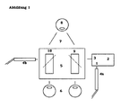
- Das Beleuchtungslicht wird (über eine geeignete Einkoppeloptik) in einen Lichtleiter geleitet und aus diesem, über eine geeignete Auskoppeloptik, in den zweiten Strahlengang des Mikroskops geleitet. Der Strahlenverlauf des Beleuchtungslichtes ist dann leicht divergent. Bedingt durch diese Fokussierung der Beobachtungsstrahlengänge auf die Beobachtungsebene (vergleiche
Abbildung 1 ) findet die Beleuchtung des Objektes in einem geringgradig anderen Einfallswinkel als die Beobachtung statt. Dadurch werden Reflexionen des Beleuchtungslichtes an optischen Grenzflächen des Patientenauges effektiv minimiert. Dabei ist es unerheblich, ob eine einfache Auflichtfotografie durchgeführt wird, oder außerhalb des Mikroskopes besondere Strahlengänge durch zusätzliche Lupen oder Kontaktgläser bei einer Fundusskopie durch den Augenarzt benutzt werden. - Die Fokussierung der Foto- oder Filmbilder erfolgt über den Sucher der Kamera. Per Lichtleiter wird das von der Kamera ausgesendete Licht an die gewünschte Stelle gebracht und das reflektierte Licht vom Kameracomputer entsprechend den Bedürfnissen der Kamera verarbeitet. Dies ermöglicht die Nutzung jeweils neuester Kameramodelle ohne kostenintensive Adaptation.
- Dieses Verfahren und die zugehörigen Vorrichtungen ermöglichen keine Stereofotografie, da nur ein Strahlengang mit einer Kamera verbunden ist. Möglich ist aber eine einfache, qualitativ hochwertige, mon-okulare Fotografie zur Dokumentation des im Blickfeld Sichtbaren. Eine Stereofotografie ist aber in sehr vielen Fällen des augenärztlichen Handelns auch gar nicht nötig.
- Die Vorteile der Erfindung sind, zusammengefasst:
- Die Möglichkeit der Nachrüstung gewöhnlicher Spaltlampenmikroskope,
- die Möglichkeit der Verwendung von Kameras jeweils neuester Bauart, ohne die Notwendigkeit einer elektronischen Adaptation,
- der Erhalt der Herstellergarantie und der Verkäufergewährleistung der Kamera, da diese nicht verändert wird,
- eine uneingeschränkte Nutzung der Kameralogik zur Belichtungs- und Beleuchtungssteuerung,
- eine zusätzliche Möglichkeit der Einleitung von Licht verschiedener Lichtquellen,
- die Möglichkeit einer Modifizierung des Beleuchtungslichtes durch Filter.
- In einem Spaltlampen-Mikroskop SL 120, Fa. Carl Zeiss Jena, D wurden in die beiden Beobachtungstrahlengänge teildurchlässige Spiegel (2) und (3) des Gerätezubehörs (zur Auskopplung von Bildern) in die geräteseitig vorhandenen Halterungen platziert. Der Objektiveingang einer Digitalkamera Canon FS 11, Fa. Canon, Tokio, Japan wurde mit Hilfe einer passgenauen (selbst gefertigten) Halterung vor dem Ausgang eines der durch die teildurchlässigen Spiegel ausgekoppelten Teilstrahlengänge zentriert platziert. Selbst auf Maß gefertigte Halterungen für einen optischen Lichtleiter Fa. Volpi, Schlieren, CH wurden am Blitz- und Videolichtausgang der Digitalkamera und am zweiten Ausgangsstutzen für ausgekoppeltes Licht des zweiten Strahlenganges des Mikroskopes (hier als Eingang für einzukoppelndes Beleuchtungslicht) angebracht und der Lichtleiter eingesetzt.
- Entsprechend den Klassifizierungsregeln der Richtlinie 93/42/EWG über Medizinprodukte (MDD) bleibt die Spaltlampe weiterhin ein nicht invasives, aktives Medizinprodukt der Klasse 1.
- Mit dieser Vorrichtung wurden von verschiedenen Freiwilligen Aufnahmen ihres Augenhintergrundes angefertigt. Die Aufnahmen waren gut ausgeleuchtet und insgesamt von guter Qualität.
- Allgemeines Schema der erfindungsgemäßen Vorrichtung:
- (1) Beleuchtungslampe (hier als integrierte Lampe der
- (2) Digital Kamera mit deren
- (3) Objektiveingang
- (4a) Lichtleiter zur Aufnahme des Lichtes von (1) und
- (4b) Abgabe des Lichtes in den
- (5) Strahlenteiler.
- (6) Mikroskopokulare (während der Erfindungsgemäßen Nutzung ohne Funktion)
- (7) Mikroskopobjektiv
- (8) Beobachtetes Gut (Patient)
- (9) Bildlichtführung
- (10) Beleuchtungslichtführung (Erfindungsgemäß)
Claims (8)
- Verfahren zur Beleuchtung des Mikroskopiergutes, insbesondere des Augenhintergrundes, während dessen Betrachtung mit einem (gewöhnlichen) augenärztlichen Stereo-Spaltlampenmikroskop, zur Fotografie oder Anfertigung von Filmen,
dadurch gekennzeichnet,
dass das Licht einer Beleuchtungslampe in das Spaltlampenmikroskop geleitet, dort durch Überlagerung (retrograd) in einen der beiden optischen Beobachtungs-Strahlengänge des Mikroskopes eingekoppelt, aus dem anderen der beiden Beobachtungs-Strahlengänge des Spaltlampenmikroskopes ein Mikroskopbild ausgekoppelt und anschließend einer Kamera zugeführt wird. - Verfahren gemäß Anspruch 1,
dadurch gekennzeichnet,
dass zur Fotografie als Beleuchtungslicht das Blitzlicht einer integrierten Blitzlampe der verwendeten Foto-Kamera verwendet wird. - Verfahren gemäß Anspruch 1,
dadurch gekennzeichnet,
dass zum Filmen als Beleuchtungslicht das Videolicht einer integrierten Videolampe der verwendeten Film-Kamera verwendet wird. - Vorrichtung optischer Bauteile und Geräte zur Beleuchtung des Mikroskopierfeldes, insbesondere des Augenhintergrundes, während dessen Betrachtung mit einem (gewöhnlichen) augenärztlichen Stereo-Spaltlampenmikroskop, zur Fotografie oder zur Anfertigung von Filmen, bestehend aus,
einer Beleuchtungslampe (1), deren Licht in das Spaltlampenmikroskop geleitet, dort durch Überlagerung mittels eines geeigneten optischen Spiegels (2) retrograd in einen der beiden optischen Strahlengänge des Mikroskopes eingekoppelt wird, aus dem anderen der beiden optischen Strahlengänge des Spaltlampenmikroskopes mittels eines weiteren optischen Spiegels (3) ein Mikroskopbild ausgekoppelt und dem Objektiveingang einer Kamera (4) zugeführt wird - sowie weiteren hilfreichen oder notwendigen optischen Komponenten, die dem allgemein bekannten Wissen der Optik entsprechen. - Vorrichtung gemäß Anspruch 4,
dadurch gekennzeichnet,
dass zum Einkoppeln des Beleuchtungslichtes und zum Auskoppeln des Mikroskopbildes für Licht teildurchlässige oder undurchlässige Spiegel verwendet werden. - Vorrichtung gemäß Anspruch 4 oder 5,
dadurch gekennzeichnet,
dass zum Leiten des Beleuchtungslichtes in das Mikroskop ein optischer Lichtleiter verwendet wird. - Vorrichtung gemäß einem der Ansprüche 4 bis 6,
dadurch gekennzeichnet,
dass zur Fotografie die Beleuchtungslampe (1) die integrierte Blitzlampe der verwendeten Fotokamera (4) ist. - Vorrichtung gemäß einem der Ansprüche 4 bis 6,
dadurch gekennzeichnet,
dass zum Filmen die Beleuchtungslampe (1) die integrierte Videolampe der verwendeten Filmkamera (4) ist.
Priority Applications (1)
| Application Number | Priority Date | Filing Date | Title |
|---|---|---|---|
| EP09004712A EP2206461B1 (de) | 2009-01-12 | 2009-04-01 | Verfahren und Vorrichtung zur Ausleuchtung des Mikroskopierfeldes, insbesondere des Augenhintergrundes, während Betrachtung mit einem Stereo-Spaltlampenmikroskop |
Applications Claiming Priority (2)
| Application Number | Priority Date | Filing Date | Title |
|---|---|---|---|
| EP09000285 | 2009-01-12 | ||
| EP09004712A EP2206461B1 (de) | 2009-01-12 | 2009-04-01 | Verfahren und Vorrichtung zur Ausleuchtung des Mikroskopierfeldes, insbesondere des Augenhintergrundes, während Betrachtung mit einem Stereo-Spaltlampenmikroskop |
Publications (2)
| Publication Number | Publication Date |
|---|---|
| EP2206461A1 true EP2206461A1 (de) | 2010-07-14 |
| EP2206461B1 EP2206461B1 (de) | 2011-10-05 |
Family
ID=41478688
Family Applications (1)
| Application Number | Title | Priority Date | Filing Date |
|---|---|---|---|
| EP09004712A Not-in-force EP2206461B1 (de) | 2009-01-12 | 2009-04-01 | Verfahren und Vorrichtung zur Ausleuchtung des Mikroskopierfeldes, insbesondere des Augenhintergrundes, während Betrachtung mit einem Stereo-Spaltlampenmikroskop |
Country Status (2)
| Country | Link |
|---|---|
| EP (1) | EP2206461B1 (de) |
| AT (1) | ATE526868T1 (de) |
Cited By (2)
| Publication number | Priority date | Publication date | Assignee | Title |
|---|---|---|---|---|
| CN104207751A (zh) * | 2013-08-24 | 2014-12-17 | 北京高景弘毅科技发展有限公司 | 有闪光功能的裂隙灯照相机 |
| CN119908649A (zh) * | 2025-04-07 | 2025-05-02 | 浙江清大视光科技有限公司 | 集成式裂隙灯眼部检测装置 |
Citations (6)
| Publication number | Priority date | Publication date | Assignee | Title |
|---|---|---|---|---|
| US3944342A (en) * | 1974-04-30 | 1976-03-16 | Codman & Shurtleff, Inc. | Photographic apparatus for slit lamp |
| GB1485592A (en) | 1974-12-19 | 1977-09-14 | Rodenstock Optik G | Multiple light source for observation instruments |
| WO1990013255A1 (de) * | 1989-05-11 | 1990-11-15 | Haag-Streit Ag Werkstätten Für Präzisionsmechanik | Photozusatz und blendenanordnung für ein binokulares mikroskop |
| WO1991006025A1 (en) * | 1989-10-11 | 1991-05-02 | Luxtec Corporation | Optical system which allows coincident viewing, illuminating and photographing |
| JPH0576498A (ja) * | 1991-09-17 | 1993-03-30 | Nikon Corp | スリツトランプマイクロスコープ |
| DE102005032501A1 (de) * | 2004-09-10 | 2006-03-30 | Werner Reis | Vorrichtung zur Untersuchung vorderer und hinterer Augenabschnitte |
-
2009
- 2009-04-01 EP EP09004712A patent/EP2206461B1/de not_active Not-in-force
- 2009-04-01 AT AT09004712T patent/ATE526868T1/de active
Patent Citations (6)
| Publication number | Priority date | Publication date | Assignee | Title |
|---|---|---|---|---|
| US3944342A (en) * | 1974-04-30 | 1976-03-16 | Codman & Shurtleff, Inc. | Photographic apparatus for slit lamp |
| GB1485592A (en) | 1974-12-19 | 1977-09-14 | Rodenstock Optik G | Multiple light source for observation instruments |
| WO1990013255A1 (de) * | 1989-05-11 | 1990-11-15 | Haag-Streit Ag Werkstätten Für Präzisionsmechanik | Photozusatz und blendenanordnung für ein binokulares mikroskop |
| WO1991006025A1 (en) * | 1989-10-11 | 1991-05-02 | Luxtec Corporation | Optical system which allows coincident viewing, illuminating and photographing |
| JPH0576498A (ja) * | 1991-09-17 | 1993-03-30 | Nikon Corp | スリツトランプマイクロスコープ |
| DE102005032501A1 (de) * | 2004-09-10 | 2006-03-30 | Werner Reis | Vorrichtung zur Untersuchung vorderer und hinterer Augenabschnitte |
Cited By (3)
| Publication number | Priority date | Publication date | Assignee | Title |
|---|---|---|---|---|
| CN104207751A (zh) * | 2013-08-24 | 2014-12-17 | 北京高景弘毅科技发展有限公司 | 有闪光功能的裂隙灯照相机 |
| CN104207751B (zh) * | 2013-08-24 | 2017-01-25 | 北京高景弘毅科技发展有限公司 | 有闪光功能的裂隙灯照相机 |
| CN119908649A (zh) * | 2025-04-07 | 2025-05-02 | 浙江清大视光科技有限公司 | 集成式裂隙灯眼部检测装置 |
Also Published As
| Publication number | Publication date |
|---|---|
| ATE526868T1 (de) | 2011-10-15 |
| EP2206461B1 (de) | 2011-10-05 |
Similar Documents
| Publication | Publication Date | Title |
|---|---|---|
| EP1535101B1 (de) | Kamera-Adapter für ein Mikroskop | |
| DE102009010448B4 (de) | Kameraadapter für ein medizinisch optisches Beobachtungsgerät und Kamera-Adapter-Kombination | |
| DE10212386B4 (de) | Umgekehrtes Mikroskop | |
| US8477416B2 (en) | Stereomicroscope | |
| CN111655119B (zh) | 近距拍摄用装置 | |
| DE10242983B4 (de) | Ophthalmo-Operationsmikroskop mit Objektbeleuchtung | |
| DE112010003402T5 (de) | Ophthalmologisches Aufnahmegerät und Kamera zur Verwendung bei ophthalmologischer Aufnahme | |
| DE102014103044A1 (de) | Chirurgisches Assistenzsystem | |
| DE102009019575A1 (de) | Stereoskopisches optisches Beobachtungsgerät und stereoskopisches optisches Beobachtungssystem | |
| WO2014068058A1 (de) | Stereomikroskop mit stereovariator | |
| DE3623394C2 (de) | Operationsmikroskop | |
| US4396260A (en) | Slit lamp having replaceable objective lens unit for observation of cornea | |
| DE102011114523A1 (de) | Modul zur Weiterleitung eines Lichtstrahls | |
| EP2206461B1 (de) | Verfahren und Vorrichtung zur Ausleuchtung des Mikroskopierfeldes, insbesondere des Augenhintergrundes, während Betrachtung mit einem Stereo-Spaltlampenmikroskop | |
| DE10130119A1 (de) | Videomikroskop | |
| DE2950809A1 (de) | Vorrichtung zur untersuchung und photographischen aufzeichnung des augenhintergrundes und verfahren zum betrieb derselben | |
| DE102008026576A1 (de) | Optisches System für ophtalmologische Geräte, insbesondere Funduskameras | |
| US10440256B2 (en) | Surgical microscope and method implemented with the surgical microscope | |
| DE102013005869A1 (de) | Verfahren zur fotografischen Beobachtung und/oder Dokumentation des Fundus eines Auges sowie Funduskamera | |
| DE10214940A1 (de) | Inverses Mikroskop | |
| DD153855A1 (de) | Vorrichtung zur netzhautfotografie | |
| DE102014109095B4 (de) | Zwischenriegel-Modul mit Bildsensor | |
| DE3146544A1 (de) | Netzhautkamera | |
| DE102021107297A1 (de) | Optisches System für die Augenchirurgie und Verfahren zum Vermeiden einer zu hohen Lichtintensität an einem digitalen Bildsensor eines Operationsmikroskops | |
| DE4015901A1 (de) | Augenfunduskamera |
Legal Events
| Date | Code | Title | Description |
|---|---|---|---|
| PUAI | Public reference made under article 153(3) epc to a published international application that has entered the european phase |
Free format text: ORIGINAL CODE: 0009012 |
|
| AK | Designated contracting states |
Kind code of ref document: A1 Designated state(s): AT BE BG CH CY CZ DE DK EE ES FI FR GB GR HR HU IE IS IT LI LT LU LV MC MK MT NL NO PL PT RO SE SI SK TR |
|
| AX | Request for extension of the european patent |
Extension state: AL BA RS |
|
| 17P | Request for examination filed |
Effective date: 20101223 |
|
| GRAP | Despatch of communication of intention to grant a patent |
Free format text: ORIGINAL CODE: EPIDOSNIGR1 |
|
| RAP1 | Party data changed (applicant data changed or rights of an application transferred) |
Owner name: TIETJEN, ANDREAS, DR., DR. |
|
| RIN1 | Information on inventor provided before grant (corrected) |
Inventor name: TIETJEN, ANDREAS, DR., DR. |
|
| GRAS | Grant fee paid |
Free format text: ORIGINAL CODE: EPIDOSNIGR3 |
|
| GRAA | (expected) grant |
Free format text: ORIGINAL CODE: 0009210 |
|
| AK | Designated contracting states |
Kind code of ref document: B1 Designated state(s): AT BE BG CH CY CZ DE DK EE ES FI FR GB GR HR HU IE IS IT LI LT LU LV MC MK MT NL NO PL PT RO SE SI SK TR |
|
| REG | Reference to a national code |
Ref country code: GB Ref legal event code: FG4D Free format text: NOT ENGLISH |
|
| REG | Reference to a national code |
Ref country code: CH Ref legal event code: EP |
|
| REG | Reference to a national code |
Ref country code: IE Ref legal event code: FG4D |
|
| REG | Reference to a national code |
Ref country code: DE Ref legal event code: R096 Ref document number: 502009001496 Country of ref document: DE Effective date: 20111208 |
|
| REG | Reference to a national code |
Ref country code: NL Ref legal event code: VDEP Effective date: 20111005 |
|
| PG25 | Lapsed in a contracting state [announced via postgrant information from national office to epo] |
Ref country code: SI Free format text: LAPSE BECAUSE OF FAILURE TO SUBMIT A TRANSLATION OF THE DESCRIPTION OR TO PAY THE FEE WITHIN THE PRESCRIBED TIME-LIMIT Effective date: 20111005 |
|
| LTIE | Lt: invalidation of european patent or patent extension |
Effective date: 20111005 |
|
| PG25 | Lapsed in a contracting state [announced via postgrant information from national office to epo] |
Ref country code: IS Free format text: LAPSE BECAUSE OF FAILURE TO SUBMIT A TRANSLATION OF THE DESCRIPTION OR TO PAY THE FEE WITHIN THE PRESCRIBED TIME-LIMIT Effective date: 20120205 Ref country code: NO Free format text: LAPSE BECAUSE OF FAILURE TO SUBMIT A TRANSLATION OF THE DESCRIPTION OR TO PAY THE FEE WITHIN THE PRESCRIBED TIME-LIMIT Effective date: 20120105 Ref country code: LT Free format text: LAPSE BECAUSE OF FAILURE TO SUBMIT A TRANSLATION OF THE DESCRIPTION OR TO PAY THE FEE WITHIN THE PRESCRIBED TIME-LIMIT Effective date: 20111005 |
|
| REG | Reference to a national code |
Ref country code: IE Ref legal event code: FD4D |
|
| PG25 | Lapsed in a contracting state [announced via postgrant information from national office to epo] |
Ref country code: LV Free format text: LAPSE BECAUSE OF FAILURE TO SUBMIT A TRANSLATION OF THE DESCRIPTION OR TO PAY THE FEE WITHIN THE PRESCRIBED TIME-LIMIT Effective date: 20111005 Ref country code: PT Free format text: LAPSE BECAUSE OF FAILURE TO SUBMIT A TRANSLATION OF THE DESCRIPTION OR TO PAY THE FEE WITHIN THE PRESCRIBED TIME-LIMIT Effective date: 20120206 Ref country code: HR Free format text: LAPSE BECAUSE OF FAILURE TO SUBMIT A TRANSLATION OF THE DESCRIPTION OR TO PAY THE FEE WITHIN THE PRESCRIBED TIME-LIMIT Effective date: 20111005 Ref country code: SE Free format text: LAPSE BECAUSE OF FAILURE TO SUBMIT A TRANSLATION OF THE DESCRIPTION OR TO PAY THE FEE WITHIN THE PRESCRIBED TIME-LIMIT Effective date: 20111005 Ref country code: NL Free format text: LAPSE BECAUSE OF FAILURE TO SUBMIT A TRANSLATION OF THE DESCRIPTION OR TO PAY THE FEE WITHIN THE PRESCRIBED TIME-LIMIT Effective date: 20111005 Ref country code: GR Free format text: LAPSE BECAUSE OF FAILURE TO SUBMIT A TRANSLATION OF THE DESCRIPTION OR TO PAY THE FEE WITHIN THE PRESCRIBED TIME-LIMIT Effective date: 20120106 |
|
| PG25 | Lapsed in a contracting state [announced via postgrant information from national office to epo] |
Ref country code: CY Free format text: LAPSE BECAUSE OF FAILURE TO SUBMIT A TRANSLATION OF THE DESCRIPTION OR TO PAY THE FEE WITHIN THE PRESCRIBED TIME-LIMIT Effective date: 20111005 |
|
| PG25 | Lapsed in a contracting state [announced via postgrant information from national office to epo] |
Ref country code: IE Free format text: LAPSE BECAUSE OF FAILURE TO SUBMIT A TRANSLATION OF THE DESCRIPTION OR TO PAY THE FEE WITHIN THE PRESCRIBED TIME-LIMIT Effective date: 20111005 Ref country code: BG Free format text: LAPSE BECAUSE OF FAILURE TO SUBMIT A TRANSLATION OF THE DESCRIPTION OR TO PAY THE FEE WITHIN THE PRESCRIBED TIME-LIMIT Effective date: 20120105 Ref country code: DK Free format text: LAPSE BECAUSE OF FAILURE TO SUBMIT A TRANSLATION OF THE DESCRIPTION OR TO PAY THE FEE WITHIN THE PRESCRIBED TIME-LIMIT Effective date: 20111005 Ref country code: CZ Free format text: LAPSE BECAUSE OF FAILURE TO SUBMIT A TRANSLATION OF THE DESCRIPTION OR TO PAY THE FEE WITHIN THE PRESCRIBED TIME-LIMIT Effective date: 20111005 Ref country code: SK Free format text: LAPSE BECAUSE OF FAILURE TO SUBMIT A TRANSLATION OF THE DESCRIPTION OR TO PAY THE FEE WITHIN THE PRESCRIBED TIME-LIMIT Effective date: 20111005 Ref country code: EE Free format text: LAPSE BECAUSE OF FAILURE TO SUBMIT A TRANSLATION OF THE DESCRIPTION OR TO PAY THE FEE WITHIN THE PRESCRIBED TIME-LIMIT Effective date: 20111005 |
|
| PLBE | No opposition filed within time limit |
Free format text: ORIGINAL CODE: 0009261 |
|
| STAA | Information on the status of an ep patent application or granted ep patent |
Free format text: STATUS: NO OPPOSITION FILED WITHIN TIME LIMIT |
|
| PG25 | Lapsed in a contracting state [announced via postgrant information from national office to epo] |
Ref country code: PL Free format text: LAPSE BECAUSE OF FAILURE TO SUBMIT A TRANSLATION OF THE DESCRIPTION OR TO PAY THE FEE WITHIN THE PRESCRIBED TIME-LIMIT Effective date: 20111005 Ref country code: RO Free format text: LAPSE BECAUSE OF FAILURE TO SUBMIT A TRANSLATION OF THE DESCRIPTION OR TO PAY THE FEE WITHIN THE PRESCRIBED TIME-LIMIT Effective date: 20111005 |
|
| PGFP | Annual fee paid to national office [announced via postgrant information from national office to epo] |
Ref country code: FR Payment date: 20120705 Year of fee payment: 4 |
|
| 26N | No opposition filed |
Effective date: 20120706 |
|
| PGFP | Annual fee paid to national office [announced via postgrant information from national office to epo] |
Ref country code: IT Payment date: 20120430 Year of fee payment: 4 |
|
| BERE | Be: lapsed |
Owner name: TIETJEN, ANDREAS, DR., DR. Effective date: 20120430 |
|
| REG | Reference to a national code |
Ref country code: DE Ref legal event code: R097 Ref document number: 502009001496 Country of ref document: DE Effective date: 20120706 |
|
| PG25 | Lapsed in a contracting state [announced via postgrant information from national office to epo] |
Ref country code: MC Free format text: LAPSE BECAUSE OF NON-PAYMENT OF DUE FEES Effective date: 20120430 |
|
| PG25 | Lapsed in a contracting state [announced via postgrant information from national office to epo] |
Ref country code: BE Free format text: LAPSE BECAUSE OF NON-PAYMENT OF DUE FEES Effective date: 20120430 |
|
| PGFP | Annual fee paid to national office [announced via postgrant information from national office to epo] |
Ref country code: DE Payment date: 20121004 Year of fee payment: 4 |
|
| PG25 | Lapsed in a contracting state [announced via postgrant information from national office to epo] |
Ref country code: MK Free format text: LAPSE BECAUSE OF FAILURE TO SUBMIT A TRANSLATION OF THE DESCRIPTION OR TO PAY THE FEE WITHIN THE PRESCRIBED TIME-LIMIT Effective date: 20111005 |
|
| PG25 | Lapsed in a contracting state [announced via postgrant information from national office to epo] |
Ref country code: ES Free format text: LAPSE BECAUSE OF FAILURE TO SUBMIT A TRANSLATION OF THE DESCRIPTION OR TO PAY THE FEE WITHIN THE PRESCRIBED TIME-LIMIT Effective date: 20120116 |
|
| PG25 | Lapsed in a contracting state [announced via postgrant information from national office to epo] |
Ref country code: FI Free format text: LAPSE BECAUSE OF FAILURE TO SUBMIT A TRANSLATION OF THE DESCRIPTION OR TO PAY THE FEE WITHIN THE PRESCRIBED TIME-LIMIT Effective date: 20111005 |
|
| PG25 | Lapsed in a contracting state [announced via postgrant information from national office to epo] |
Ref country code: MT Free format text: LAPSE BECAUSE OF FAILURE TO SUBMIT A TRANSLATION OF THE DESCRIPTION OR TO PAY THE FEE WITHIN THE PRESCRIBED TIME-LIMIT Effective date: 20111005 |
|
| REG | Reference to a national code |
Ref country code: CH Ref legal event code: PL |
|
| GBPC | Gb: european patent ceased through non-payment of renewal fee |
Effective date: 20130401 |
|
| PG25 | Lapsed in a contracting state [announced via postgrant information from national office to epo] |
Ref country code: CH Free format text: LAPSE BECAUSE OF NON-PAYMENT OF DUE FEES Effective date: 20130430 Ref country code: LI Free format text: LAPSE BECAUSE OF NON-PAYMENT OF DUE FEES Effective date: 20130430 Ref country code: DE Free format text: LAPSE BECAUSE OF NON-PAYMENT OF DUE FEES Effective date: 20131101 Ref country code: GB Free format text: LAPSE BECAUSE OF NON-PAYMENT OF DUE FEES Effective date: 20130401 |
|
| REG | Reference to a national code |
Ref country code: FR Ref legal event code: ST Effective date: 20131231 |
|
| REG | Reference to a national code |
Ref country code: DE Ref legal event code: R119 Ref document number: 502009001496 Country of ref document: DE Effective date: 20131101 |
|
| PG25 | Lapsed in a contracting state [announced via postgrant information from national office to epo] |
Ref country code: IT Free format text: LAPSE BECAUSE OF NON-PAYMENT OF DUE FEES Effective date: 20130401 Ref country code: FR Free format text: LAPSE BECAUSE OF NON-PAYMENT OF DUE FEES Effective date: 20130430 |
|
| PG25 | Lapsed in a contracting state [announced via postgrant information from national office to epo] |
Ref country code: TR Free format text: LAPSE BECAUSE OF FAILURE TO SUBMIT A TRANSLATION OF THE DESCRIPTION OR TO PAY THE FEE WITHIN THE PRESCRIBED TIME-LIMIT Effective date: 20111005 |
|
| PG25 | Lapsed in a contracting state [announced via postgrant information from national office to epo] |
Ref country code: LU Free format text: LAPSE BECAUSE OF NON-PAYMENT OF DUE FEES Effective date: 20120401 |
|
| PG25 | Lapsed in a contracting state [announced via postgrant information from national office to epo] |
Ref country code: HU Free format text: LAPSE BECAUSE OF FAILURE TO SUBMIT A TRANSLATION OF THE DESCRIPTION OR TO PAY THE FEE WITHIN THE PRESCRIBED TIME-LIMIT Effective date: 20090401 |
|
| REG | Reference to a national code |
Ref country code: AT Ref legal event code: MM01 Ref document number: 526868 Country of ref document: AT Kind code of ref document: T Effective date: 20140401 |
|
| PG25 | Lapsed in a contracting state [announced via postgrant information from national office to epo] |
Ref country code: AT Free format text: LAPSE BECAUSE OF NON-PAYMENT OF DUE FEES Effective date: 20140401 |