EP1535101B1 - Kamera-Adapter für ein Mikroskop - Google Patents
Kamera-Adapter für ein Mikroskop Download PDFInfo
- Publication number
- EP1535101B1 EP1535101B1 EP03793624A EP03793624A EP1535101B1 EP 1535101 B1 EP1535101 B1 EP 1535101B1 EP 03793624 A EP03793624 A EP 03793624A EP 03793624 A EP03793624 A EP 03793624A EP 1535101 B1 EP1535101 B1 EP 1535101B1
- Authority
- EP
- European Patent Office
- Prior art keywords
- camera
- microscope
- adapter
- connecting pieces
- cameras
- Prior art date
- Legal status (The legal status is an assumption and is not a legal conclusion. Google has not performed a legal analysis and makes no representation as to the accuracy of the status listed.)
- Expired - Lifetime
Links
- 230000003287 optical effect Effects 0.000 claims abstract description 14
- 238000010168 coupling process Methods 0.000 abstract description 4
- 238000005859 coupling reaction Methods 0.000 abstract description 4
- 230000002349 favourable effect Effects 0.000 description 3
- 238000003384 imaging method Methods 0.000 description 3
- 230000008878 coupling Effects 0.000 description 2
- 238000005286 illumination Methods 0.000 description 2
- 239000013589 supplement Substances 0.000 description 2
- 239000000654 additive Substances 0.000 description 1
- 230000000996 additive effect Effects 0.000 description 1
- 239000002872 contrast media Substances 0.000 description 1
- 230000001419 dependent effect Effects 0.000 description 1
- 238000011161 development Methods 0.000 description 1
- 230000018109 developmental process Effects 0.000 description 1
- 238000003745 diagnosis Methods 0.000 description 1
- 230000005284 excitation Effects 0.000 description 1
- 239000007850 fluorescent dye Substances 0.000 description 1
- 230000005484 gravity Effects 0.000 description 1
- 238000001000 micrograph Methods 0.000 description 1
- 210000001747 pupil Anatomy 0.000 description 1
- 230000011514 reflex Effects 0.000 description 1
- 230000001105 regulatory effect Effects 0.000 description 1
- 238000001228 spectrum Methods 0.000 description 1
Images
Classifications
-
- G—PHYSICS
- G02—OPTICS
- G02B—OPTICAL ELEMENTS, SYSTEMS OR APPARATUS
- G02B21/00—Microscopes
- G02B21/36—Microscopes arranged for photographic purposes or projection purposes or digital imaging or video purposes including associated control and data processing arrangements
- G02B21/362—Mechanical details, e.g. mountings for the camera or image sensor, housings
-
- G—PHYSICS
- G03—PHOTOGRAPHY; CINEMATOGRAPHY; ANALOGOUS TECHNIQUES USING WAVES OTHER THAN OPTICAL WAVES; ELECTROGRAPHY; HOLOGRAPHY
- G03B—APPARATUS OR ARRANGEMENTS FOR TAKING PHOTOGRAPHS OR FOR PROJECTING OR VIEWING THEM; APPARATUS OR ARRANGEMENTS EMPLOYING ANALOGOUS TECHNIQUES USING WAVES OTHER THAN OPTICAL WAVES; ACCESSORIES THEREFOR
- G03B17/00—Details of cameras or camera bodies; Accessories therefor
- G03B17/48—Details of cameras or camera bodies; Accessories therefor adapted for combination with other photographic or optical apparatus
Definitions
- the present technical solution relates to a camera adapter by which it is possible, any video and photo cameras to an existing image decoupling z.
- B. connect the beam splitter of a microscope.
- the adapter can also be used for stereomicroscopes and in particular for eye microscopes.
- lensless cameras are connected via a corresponding coupling to a special optical output on the microscope or stereomicroscope for the documentation of microscope images.
- a special optical output on the microscope or stereomicroscope for the documentation of microscope images.
- coupling systems for example, T2, C-mount or various bayonet connections are used.
- the image information for this particular camera output is generated by pupil division of the optical beam path or a stereo beam path and imaged by a special imaging optics on the appropriate recording medium.
- the adapter includes a motorized zoom lens and has a ring to which video or photo cameras with C-mount or bayonet connection can be connected.
- these cameras are usually special solutions exclusively for technical areas, more and more solutions were sought.
- Another option for obtaining images is cameras that are attached to the eyepiece socket or to the eyepiece of the optical device.
- the tube image of a slit lamp or a microscope is imaged via a special adapter and the camera lens onto a recording medium.
- the US 5,053,794 describes an adapter ring, which is suitable for example for connecting a camera or video camera with the eyepiece of a telescope or microscope.
- the adapter for connecting a camera to the phototube of a microscope is described.
- the adapter has a lens system and a mounting bracket. From the lens system, the intermediate image generated in the microscope is imaged infinitely and projected on the lens of the connected camera on its recording medium.
- the mounting bracket is attached to the phototube of the microscope and has a mounting screw, which engages in the tripod socket on the camera and fixes the camera so. Since there is no uniform standard for the distance of the tripod thread from the optical axis or for the arrangement of the tripod thread on the camera body, these dimensions are quite different in the cameras.
- the adapter described is therefore usable only for certain cameras and must be adapted for other cameras.
- a combined adapter for connecting a video and at least one camera to a surgical microscope is in the DE 38 04 198 A1 described.
- the imaging beam path branched off for imaging is optionally made available for one of the cameras.
- An image rotator can thus be dispensed with.
- a video accessory for a microscope without Fototubus is in the US 5,568,188 described.
- the video add-on is connected via connecting elements with the Connected to a microscope.
- the adjustment of the additional video with respect to the optical axis of the microscope by means of existing screws.
- the set position of the video accessory is fixed by means of springs and locking screws.
- the optical axis of the video accessory subtends an angle with the optical axis of the microscope so that the images viewed by both elements are not equal. It is therefore not possible to have the image viewed in the microscope simultaneously recorded by the video camera.
- the settings on the microscope must be changed. This makes it difficult to ensure that the video recording with the previously seen by the observer images of the eye to be examined are identical. In addition, this "double" examination causes a much higher expenditure of time and thus a greater burden on the patient.
- the US 5,134,515 relates to a photo supplement and a diaphragm assembly for a binocular microscope, in particular an eye microscope.
- the photo additive is arranged in the observation beam path between the magnification changer and the eyepiece tube.
- this photo supplement is a movable mirror, which pivots when actuated in the observation beam path and this deflects in the direction of the existing phototube and the attached camera.
- the aperture setting for taking a photo is changed during operation. With a little time delay, the shutter of the camera and the existing flashlight are pressed and taken a picture of the eye. Thereafter, all moving parts go back to their original position either by spring force or by gravity. Thus, the observation beam path is released again and the observation through the eyepieces can be continued.
- both 35 mm and instant cameras can be used.
- the added photo is not suitable. In addition, it is disadvantageous that no observation is possible during the time in which photographs are taken.
- the present technical solution is based on the task of developing an adapter for connecting a preferably digital camera to a microscope, in particular an ophthalmic microscope.
- the adapter should be equally suitable for different cameras and allow a simple change of the camera.
- the camera should be able to be arranged so that the viewer can view the object both on the microscope eyepieces and on the rear wall of the camera body, monitor, without having to change its seating position significantly.
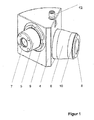
- FIG. 1 shows the camera adapter for a microscope, in particular an ophthalmic microscope 1.
- an additional image output element 2 such as folding mirror or beam splitter and an ambient light 3 for object field illumination in slit projectors required.
- the to be arranged between the Jardinauskoppelelement 2 and the camera camera adapter consists of a housing 4 with two connecting pieces 5 and 6.
- the microscope-side connection pipe 5 preferably has a quick-change device 9 as other microscope accessory units on known and has a tubular lens 7. With this Quick change device 9 , the camera adapter is force-centered, so that the optical axis of the camera coincides with that of the microscope 1 and an optical channel of a stereomicroscope.
- the camera-side connecting piece 6 has a filter thread 10 and has an eyepiece optics 8.
- the filter thread 10 is preferably M37 and can be adapted by the use of intermediate rings 11 to different diameters of filter threads 10 and reivzylindem.
- Commercially available digital cameras with lenses, filter threads and preferably also a monitor on the back of the housing are to be used.
- the camera-side connecting piece 6 is rotatable in the housing 4 , so that the filter thread 10 at times obliquely sitting camera can be brought together with the connecting piece 6 in a straight position. With the aid of a locking device 12 , a renewed rotation of the connecting piece 6 is prevented.
- the camera adapter is advantageously designed via a combined prism mirror arrangement such that an ergonomically favorable viewing of the monitor located on the rear wall of the camera and normal operation is possible.
- the environment light 3 which may be required for the photographic documentation, consists of a light-emitting diode, which emits white light in the special case. Their brightness can be regulated by a dimmer 13 and adapted to the different lighting conditions, so that an optimal representation of the slit image in a low-light environment (eye) is ensured.
- the power supply via the power supply of the microscope 1.
- the ambient light 3 may have a Aufsteckzapfen, which fits into an opening provided on the microscope 1 . The ambient light 3 is then switched on when in darkened rooms gap shots are made and the location of the slit image is to be displayed on the eye.
- the LED is based, for example, on a powerful blue LED with a wavelength of 450 nm, which excites a special layer at approx. 550 nm.
- the light maxima result in a bluish white, very intense light. This allows the light source as excitation light for fluorescence studies, d. H. be used for the diagnosis with contrast or fluorescence agents.
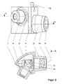
- a 90 ° prism 14 and a mirror 15 are arranged as additional beam-guiding elements so that the optical axes of the connecting pieces 5 and 6 form an angle greater than 90 °, but smaller than 180 °.
- FIG. 2 the camera adapter in a sectional view. For example, an angle of 120 ° is included to bring the camera into an ergonomic position favorable to the observer.
- the additional beam steering elements also have different heights of the connecting pieces 5 and 6 result, whereby the favorable ergonomic arrangement is further improved.
- the even mirroring creates a true-to-the-edge image for the camera to be connected.
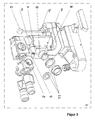
- the use of the camera adapter on an eye microscope is in FIG. 3 shown.
- the technical solution was a camera adapter for connecting digital cameras, preferably with a monitor on the rear wall of the housing, to a microscope and in particular an eye microscope created.
- the camera adapter is suitable for the use of intermediate rings for different cameras with a filter thread and makes it easy to change the camera.
- the camera can always be positioned in such a way that the observer can view the object both via the eyepieces and via the camera monitor without having to significantly change his sitting position.
- the use of an ambient light with a controllable LED has a constant spectrum at all brightness settings, provides for difficult lighting conditions enough power reserves and produces a very small grain reflex.
- the higher, constant color temperature of, for example, a white light LED leads, in addition to the slit illumination, to more contrasty slit images.
- the environment light has a very simple structure, with a long life and reliability and can be easily connected to the power supply of the microscope.
Landscapes
- Physics & Mathematics (AREA)
- General Physics & Mathematics (AREA)
- Engineering & Computer Science (AREA)
- Multimedia (AREA)
- Chemical & Material Sciences (AREA)
- Analytical Chemistry (AREA)
- Optics & Photonics (AREA)
- Microscoopes, Condenser (AREA)
- Studio Devices (AREA)
- Lens Barrels (AREA)
- Structure And Mechanism Of Cameras (AREA)
- Accessories Of Cameras (AREA)
Description
- Die vorliegende technische Lösung betrifft einen Kamera-Adapter durch den es möglich ist, beliebige Video- und Fotokameras an ein vorhandenes Bildauskoppelsystem z. B. den Strahlenteiler eines Mikroskops anzuschließen. Der Adapter kann auch für Stereomikroskope und insbesondere für Augenmikroskope verwendet werden.
- Nach dem bekannten Stand der Technik werden zur Dokumentation von Mikroskopbildem objektivlose Kameras über eine entsprechende Kupplung an einen speziellen optischen Ausgang am Mikroskop bzw. Stereomikroskop angeschlossen. Als übliche Kupplungs-Systeme kommen dabei beispielsweise T2, C-Mount oder verschiedene Bajonettanschlüsse zur Anwendung. Die Bildinformation für diesen speziellen Kamera-Ausgang wird durch Pupillenteilung des optischen Strahlengangs bzw. eines Stereostrahlenganges erzeugt und über eine spezielle Abbildungsoptik auf das entsprechende Aufnahmemedium abgebildet. Bei der in der
US 5,652,676 beschriebenen Lösung beinhaltet der Adapter ein motorisch angetriebenes Zoom-Objektiv und verfügt über einen Ring, an den Video- oder Fotokameras mit C-Mount oder Bajonettanschluss angeschlossen werden können. Da diese Kameras jedoch meist Speziallösungen ausschließlich für technische Bereiche darstellen, wurde verstärkt nach anderen Lösungen gesucht. - Eine weitere Möglichkeit der Bildgewinnung stellen Kameras dar, die am Okularstutzen oder am Okular des optischen Gerätes angebracht werden. In der
EP 0 274 038 ist eine derartige Lösung beschrieben, bei der das Tubusbild einer Spaltlampe oder eines Mikroskops über einen speziellen Adapter und das Kameraobjektiv auf ein Aufnahmemedium abgebildet wird. DieUS 5,053,794 beschreibt einen Adapterring, der beispielsweise zum verbinden einer Foto- oder Videokamera mit dem Okular eines Teleskops oder Mikroskops geeignet ist. Bei diesen Lösungen können zwar "normale" Spiegelreflex-Kamera zum Einsatz kommen, allerdings wirkt sich nachteilig aus, dass dadurch bei angeschlossener Kamera eine binokulare Beobachtung ausgeschlossen ist. - In der Gebrauchsmuster-Anmeldung
DE 200 10 421 U1 wird ein Adapter zum Anschließen einer Kamera an den Fototubus eines Mikroskops beschrieben. Der Adapter verfügt dabei über ein Linsensystem und einen Haltebügel. Vom Linsensystem wird das im Mikroskop erzeugte Zwischenbild nach unendlich abgebildet und über das Objektiv der angeschlossenen Kamera auf dessen Aufnahmemedium projiziert. Der Haltebügel ist am Fototubus des Mikroskops befestigt und weist eine Befestigungsschraube auf, die in das an der Kamera vorhanden Stativgewinde greift und die Kamera so fixiert. Da es für den Abstand des Stativgewindes von der optischen Achse bzw. für die Anordnung des Stativgewindes am Kameragehäuse keinen einheitlichen Standard gibt, sind diese Maße bei den Kameras doch recht verschieden. Der beschriebene Adapter ist somit nur für bestimmte Kameras nutzbar und muss für andere Kameras angepasst werden. - Ein kombinierter Adapter zum Anschluss einer Video- und mindestens einer Fotokamera an ein Operationsmikroskop wird in der
DE 38 04 198 A1 beschrieben. Über zwei reflektierende, optische Elemente, von denen eines schwenkbar angeordnet ist, wird der zur Bildgebung abgezweigte Abbildungsstrahlengang wahlweise für eine der Kameras zur Verfügung gestellt. Um das Ausmaß des Adapters möglichst gering zu halten erfährt das vom Objekt kommende Licht eine geradzahlige Anzahl von Reflexionen, damit sowohl von der Video- als auch von der Fotokamera seitenrichtige Bilder aufgezeichnet werden. Auf einen Bildrotator kann somit verzichtet werden. - Ein Videozusatz für ein Mikroskop ohne Fototubus wird in der
US 5,568,188 beschrieben. Der Videozusatz wird dabei über Verbindungselemente mit dem Mikroskop verbunden. Die Justierung des Videozusatzes bezüglich der optischen Achse des Mikroskops erfolgt mittels vorhandener Schrauben. Die eingestellte Position des Videozusatzes wird mit Hilfe von Federn und Sicherungsschrauben fixiert. Die optische Achse des Videozusatzes schließt mit der optischen Achse des Mikroskops einen Winkel ein, so dass die von beiden Elementen betrachteten Bilder nicht gleich sind. Es ist somit nicht möglich das im Mikroskop betrachtete Bild gleichzeitig von der Videokamera aufnehmen zu lassen. Für die Videodokumentation sind die Einstellungen am Mikroskop zu verändern. Dadurch ist nur schwer sicher zu stellen, dass die Videoaufzeichnung mit den zuvor vom Beobachter gesehenen Bildern des zu untersuchenden Auges identisch sind. Außerdem bewirkt diese "doppelte" Untersuchung einen wesentlich höheren zeitlichen Aufwand und damit eine größere Belastung des Patienten. - Die
US 5,134,515 betrifft einen Fotozusatz und eine Blendenanordnung für ein binokulares Mikroskop, insbesondere ein Augenmikroskop. Der Fotozusatz ist dabei im Beobachtungsstrahlengang zwischen dem Vergrößerungswechsler und dem Okulartubus angeordnet. In diesem Fotozusatz befindet sich ein beweglicher Spiegel, der bei Betätigung in den Beobachtungsstrahlengang einschwenkt und diesen in Richtung des vorhandenen Fototubus und der daran angeschlossenen Fotokamera umlenkt. Gleichzeitig wird bei der Betätigung die Blendeneinstellung für die fotografische Aufnahme geändert. Mit einer geringen Zeitverzögerung wird der Auslöser der Kamera und die vorhandene Blitzleuchte betätigt und eine Aufnahme des Auges gemacht. Danach gehen alle bewegten Teile entweder durch Federkraft oder durch Schwerkraft in ihre ursprüngliche Position zurück. Somit ist der Beobachtungsstrahlengang wieder frei gegeben und die Beobachtung durch die Okulare kann fortgesetzt werden. Durch den Anbau unterschiedlicher Objektivtuben sind sowohl Kleinbild- als auch Sofortbildkameras einsetzbar. Für die Aufzeichnung von Videosequenzen ist der Fotozusatz allerdings nicht geeignet. Außerdem wirkt sich nachteilig aus, dass während der Zeit, in der Fotoaufnahmen gemacht werden, keine Beobachtung möglich ist. - Der vorliegenden technischen Lösung liegt die Aufgabe zugrunde einen Adapter für den Anschluss einer vorzugsweise digitalen Kamera an ein Mikroskop, insbesondere ein Augenmikroskop zu entwickeln. Der Adapter soll für unterschiedliche Kameras gleichermaßen geeignet sein und einen einfachen Wechsel der Kamera ermöglichen. Die Kamera soll dabei so angeordnet werden können, dass der Betrachter das Objekt sowohl über die Mikroskopokulare als auch den, an der Rückwand des Kameragehäuses befindliche, Monitor betrachten kann, ohne dabei seine Sitzposition wesentlich verändern zu müssen.
- Diese Aufgabe wird dabei durch die Merkmale des unabhängigen Anspruchs gelöst. Bevorzugte Weiterbildungen und Ausgestaltungen sind Gegenstand der abhängigen Ansprüche.
- Die technische Lösung wird nachfolgend anhand eines Ausführungsbeispieles beschrieben. Dazu zeigen:
- Figur 1:
- den Prinzipaufbau des erfindungsgemäßen Kamera-Adapters,
- Figur 2:
- den Kamera-Adapter mit einer Schnittansicht A-A und
- Figur 3:
- die Verwendung des Kamera-Adapters an einem Mikroskop.
-
Figur 1 zeigt den Kamera-Adapter für ein Mikroskop, insbesondere ein Augenmikroskop 1. Zur fotografischen Dokumentation der Abbilder sind an derartigen Geräten ein zusätzliches Bildauskoppelelement 2, wie Klappspiegel oder Strahlenteiler und eine Umfeldleuchte 3 zur Objektfeldbeleuchtung bei Spaltprojektoren erforderlich. Der zwischen dem Bildauskoppelelement 2 und der Kamera anzuordnende Kamera-Adapter besteht aus einem Gehäuse 4 mit zwei Anschlussstutzen 5 und 6. Der mikroskopseitige Anschlussstutzen 5 weist vorzugsweise eine Schnellwechseleinrichtung 9 wie von anderen Mikroskopzubehöreinheiten bekannt auf und verfügt über eine Tubusoptik 7. Durch diese Schnellwechseleinrichtung 9 wird der Kamera-Adapter zwangszentriert, so dass die optische Achse der Kamera mit der des Mikroskops 1 bzw. einem optischen Kanal eines Stereomikroskops zusammenfällt. - Im Gegensatz dazu hat der kameraseitige Anschlussstutzen 6 ein Filtergewinde 10 und verfügt über eine Okularoptik 8. Das Filtergewinde 10 ist vorzugsweise M37 und kann durch die Verwendung von Zwischenringen 11 an verschiedene Durchmesser von Filtergewinden 10 bzw. Objektivzylindem angepasst werden. Zum Einsatz sollen handelsübliche Digitalkameras mit Objektiv, Filtergewinde und vorzugsweise auch einem Monitor an der Gehäuserückseite kommen. Der kameraseitige Anschlussstutzen 6 ist im Gehäuse 4 drehbar, so das die am Filtergewinde 10 mitunter schief sitzende Kamera zusammen mit dem Anschlussstutzen 6 in eine gerade Lage gebracht werden kann. Mit Hilfe einer Feststellvorrichtung 12 wird ein erneutes verdrehen des Anschlussstutzens 6 verhindert. Der Kamera-Adapter ist über eine kombinierte Prismen-Spiegelanordnung vorteilhafterweise so ausgebildet, dass eine ergonomisch günstige Betrachtung des an der Rückwand der Kamera befindlichen Monitors und eine gewohnte Bedienung möglich ist.
- Die für die fotografische Dokumentation gegebenenfalls erforderliche Umfeldleuchte 3 besteht aus einer Leuchtdiode, die im speziellen Fall Weiß-Licht aussendet. Ihre Helligkeit kann über einen Dimmer 13 reguliert und den unterschiedlichen Beleuchtungsverhältnissen angepasst werden, so dass eine optimale Darstellung des Spaltbildes auf einem günstig ausgeleuchteten Umfeld (Auge) gewährleistet wird. Die Stromversorgung erfolgt über das Netzteil des Mikroskops 1. Die Umfeldleuchte 3 kann über einen Aufsteckzapfen verfügen, der in eine am Mikroskop 1 vorhandene Öffnung passt. Die Umfeldleuchte 3 wird dann zugeschaltet, wenn in abgedunkelten Räumen Spaltaufnahmen gemacht werden und der Ort des Spaltbildes auf dem Auge dargestellt werden soll.
- In einer besonderen Ausführung basiert die LED beispielsweise auf einer leistungsstarken blauen LED mit einer Wellenlänge von 450nm, die eine spezielle Schicht bei ca. 550 nm zum Leuchten anregt. Die Leuchtmaxima ergeben dabei ein bläulich weißes, sehr intensives Licht. Dadurch kann die Lichtquelle auch als Anregungslicht für Fluoreszenzuntersuchungen, d. h. für die Diagnose mit Kontrast- bzw. Fluoreszenzmitteln genutzt werden.
- Im Gehäuse 4 des Kamera-Adapters sind ein 90°-Prisma 14 und ein Spiegel 15 als zusätzliche strahllenkende Elemente so angeordnet, dass die optischen Achsen der Anschlussstutzen 5 und 6 einen Winkel größer 90°, aber kleiner 180° einschließen. Dazu zeigt
Figur 2 den Kamera-Adapter in einer Schnittdarstellung. Beispielsweise wird ein Winkel von 120° eingeschlossen, um die Kamera in eine für den Beobachter günstige ergonomische Position zu bringen. Die zusätzlich strahllenkenden Elemente haben außerdem unterschiedliche Höhen der Anschlussstutzen 5 und 6 zur Folge, wodurch die günstige ergonomische Anordnung noch verbessert wird. Außerdem wird durch die geradzahlige Spiegelung ein seitenrichtiges aufrechtes Bild für die anzuschließende Kamera erzeugt. Die Verwendung des Kamera-Adapters an einem Augenmikroskop wird inFigur 3 dargestellt. - Mit der technischen Lösung wurde ein Kamera-Adapter zum Anschluss digitaler Kameras, vorzugsweise mit einem Monitor an der Rückwand des Gehäuses, an ein Mikroskop und insbesondere ein Augenmikroskop geschaffen. Der Kamera-Adapter ist durch die Verwendung von Zwischenringen für unterschiedliche Kameras, die über ein Filtergewinde verfügen, geeignet und ermöglicht einen einfachen Wechsel der Kamera. Die Kamera kann dabei stets so positioniert werden, dass der Betrachter das Objekt sowohl über die Okulare als auch über den Kameramonitor betrachten kann, ohne dabei seine Sitzposition wesentlich verändern zu müssen.
- Die Verwendung einer Umfeldleuchte mit einer regelbaren LED hat ein konstantes Spektrum bei allen Helligkeitseinstellungen, bietet für schwierige Beleuchtungsverhältnisse genügend Leistungsreserven und erzeugt einen sehr kleinen Korneareflex. Die höhere, konstant bleibende Farbtemperatur beispielsweise einer Weißlicht-LED führt in Ergänzung mit der Spaltbeleuchtung zu kontrastreicheren Spaltaufnahmen. Die Umfeldleuchte weist einen sehr einfachen Aufbau, bei einer hohen Lebensdauer und Zuverlässigkeit auf und kann problemlos an die Stromversorgung des Mikroskops angeschlossen werden.
-
- 1
- Mikroskop
- 2
- Bildauskoppelelement
- 3
- Umfeldleuchte
- 4
- Gehäuse
- 5
- Anschlussstutzen, mikroskopseitig
- 6
- Anschlussstutzen, kameraseitig
- 7
- Tubusoptik
- 8
- Okularoptik
- 9
- Schnellwechseleinrichtung
- 10
- Filtergewinde
- 11
- Zwischenringe
- 12
- Feststellvorrichtung
- 13
- Dimmer
- 14
- Prisma
- 15
- Spiegel
Claims (2)
- Kamera-Adapter für ein Mikroskop (1), welches zur fotografischen Dokumentation der Abbilder über ein zusätzliches Bildauskoppelelement (2) verfügt, bei dem der zwischen Bildauskoppelelement (2) und Kamera anzuordnende Kamera-Adapter aus einem Gehäuse (4) mit zwei Anschlussstutzen (5, 6) besteht und dessen kameraseitiger Anschlussstutzen (6) ein Filtergewinde (10) aufweist, dadurch gekennzeichnet, dass der mikroskopseitige Anschlussstutzen (5) über eine Tubusoptik (7) und eine Schnellwechseleinrichtung (9) und der kameraseitige Anschlussstutzen (6) über eine Okularoptik (8) verfügen und die optischen Achsen der Anschlussstutzen (5, 6) einen Winkel größer 90°, aber kleiner 180° einschließen, wobei zwischen der Tubusoptik (7) des mikroskopseitigen Anschlussstutzens (5) und der Okularoptik (8) des kameraseitigen Anschlussstutzens (6) ein Prisma (14) und ein Spiegel (15) als zusätzlich strahllenkende Elemente derart angeordnet sind, dass durch eine geradzahlige Spiegelung ein seitenrichtiges aufrechtes Bild für die Kamera erzeugt wird und der Betrachter das Objekt sowohl über die Mikroskopokulare als auch über den Kameramonitor betrachten kann, ohne dabei seine Sitzposition wesentlich verändern zu müssen.
- Kamera-Adapter nach Anspruch 1, dadurch gekennzeichnet, dass der kameraseitige Anschlussstutzen (6) drehbar ist und über eine Feststellvorrichtung (11) verfügt, dass dessen Filtergewinde (10) vorzugsweise ein Gewinde M37 ist und dass dieses Filtergewinde (10) durch Zwischenringe (12) an unterschiedliche Gewindedurchmesser angepasst werden kann.
Applications Claiming Priority (3)
| Application Number | Priority Date | Filing Date | Title |
|---|---|---|---|
| DE10240720A DE10240720A1 (de) | 2002-09-04 | 2002-09-04 | Kamera-Adapter für optische Geräte, insbesondere Mikroskope |
| DE10240720 | 2002-09-04 | ||
| PCT/EP2003/007876 WO2004023185A1 (de) | 2002-09-04 | 2003-07-18 | Kamera-adapter füroptische geräte, insbesondere mikroskope |
Publications (2)
| Publication Number | Publication Date |
|---|---|
| EP1535101A1 EP1535101A1 (de) | 2005-06-01 |
| EP1535101B1 true EP1535101B1 (de) | 2010-10-20 |
Family
ID=31895642
Family Applications (1)
| Application Number | Title | Priority Date | Filing Date |
|---|---|---|---|
| EP03793624A Expired - Lifetime EP1535101B1 (de) | 2002-09-04 | 2003-07-18 | Kamera-Adapter für ein Mikroskop |
Country Status (6)
| Country | Link |
|---|---|
| US (1) | US7394979B2 (de) |
| EP (1) | EP1535101B1 (de) |
| JP (1) | JP2005537513A (de) |
| AT (1) | ATE485534T1 (de) |
| DE (2) | DE10240720A1 (de) |
| WO (1) | WO2004023185A1 (de) |
Families Citing this family (26)
| Publication number | Priority date | Publication date | Assignee | Title |
|---|---|---|---|---|
| JP4754832B2 (ja) * | 2005-01-06 | 2011-08-24 | 株式会社 ニコンビジョン | 実体顕微鏡 |
| GB2451589B (en) * | 2005-01-06 | 2009-08-19 | Nikon Vision Co Ltd | Stereomicroscope |
| ITMI20050019A1 (it) * | 2005-01-07 | 2006-07-08 | Fraen Corp Srl | Microscopio a fluorescenza in luce trasmessa e kit di adattamento di un microscopio alla modalita' di lavoro a fluorescenza in luce trasmessa |
| DE102006020737A1 (de) * | 2006-05-04 | 2007-11-08 | Westfälische Wilhelms-Universität Münster | Bewegungsdetektierendes modulares Mikroskopsystem |
| DE102006022276B4 (de) * | 2006-05-11 | 2011-07-21 | Leica Microsystems CMS GmbH, 35578 | Mikroskop mit Kameraabgang und Kameraadapter |
| US8624967B2 (en) * | 2006-10-17 | 2014-01-07 | Dan O'Connell | Integrated portable in-situ microscope |
| US8982203B2 (en) * | 2007-06-06 | 2015-03-17 | Karl Storz Gmbh & Co. Kg | Video system for viewing an object on a body |
| JP4989423B2 (ja) * | 2007-10-30 | 2012-08-01 | オリンパス株式会社 | 光学顕微鏡 |
| ES2617664T3 (es) | 2009-03-11 | 2017-06-19 | Sakura Finetek U.S.A., Inc. | Procedimiento de enfoque automático y dispositivo de enfoque automático |
| EP2550522B1 (de) | 2010-03-23 | 2016-11-02 | California Institute of Technology | Hochauflösende optofluidische mikroskope für 2d- und 3d-bildgebung |
| US10139613B2 (en) | 2010-08-20 | 2018-11-27 | Sakura Finetek U.S.A., Inc. | Digital microscope and method of sensing an image of a tissue sample |
| US9569664B2 (en) | 2010-10-26 | 2017-02-14 | California Institute Of Technology | Methods for rapid distinction between debris and growing cells |
| WO2012058233A2 (en) * | 2010-10-26 | 2012-05-03 | California Institute Of Technology | Scanning projective lensless microscope system |
| US9643184B2 (en) | 2010-10-26 | 2017-05-09 | California Institute Of Technology | e-Petri dishes, devices, and systems having a light detector for sampling a sequence of sub-pixel shifted projection images |
| WO2012119094A2 (en) | 2011-03-03 | 2012-09-07 | California Institute Of Technology | Light guided pixel |
| USD690341S1 (en) * | 2012-03-13 | 2013-09-24 | Yokogawa Electric Corporation | Scanner for confocal microscope |
| USD690754S1 (en) * | 2012-03-13 | 2013-10-01 | Yokogawa Electric Corporation | Scanner for confocal microscope |
| DE102013103971A1 (de) | 2013-04-19 | 2014-11-06 | Sensovation Ag | Verfahren zum Erzeugen eines aus mehreren Teilbildern zusammengesetzten Gesamtbilds eines Objekts |
| USD722094S1 (en) * | 2013-08-02 | 2015-02-03 | Carl Zeiss Meditec Ag | Microscope having a handle |
| US20150124070A1 (en) * | 2013-11-01 | 2015-05-07 | Srinivas Dutt | Eyepiece adapter for recording and transmitting images |
| US10007102B2 (en) | 2013-12-23 | 2018-06-26 | Sakura Finetek U.S.A., Inc. | Microscope with slide clamping assembly |
| US11280803B2 (en) | 2016-11-22 | 2022-03-22 | Sakura Finetek U.S.A., Inc. | Slide management system |
| US11782254B2 (en) | 2020-07-24 | 2023-10-10 | United Scope LLC | Digital microscopy system and graphical user interface |
| CN114576530B (zh) * | 2021-12-29 | 2023-09-05 | 上海航天控制技术研究所 | 一种火星探测用回拍测量传感器 |
| USD966384S1 (en) * | 2022-04-08 | 2022-10-11 | Xiaoli Jiang | Microscope camera |
| CN117192758A (zh) * | 2022-05-30 | 2023-12-08 | 苏州速迈医学科技股份有限公司 | 一种光学适配装置及手术显微镜 |
Citations (2)
| Publication number | Priority date | Publication date | Assignee | Title |
|---|---|---|---|---|
| DE3804198A1 (de) * | 1987-02-16 | 1988-08-25 | Olympus Optical Co | Adapter fuer mikroskope |
| DE19938466A1 (de) * | 1998-08-21 | 2000-02-24 | Kyungil High Technology Co Ltd | Bildverarbeitungssystem zur Verwendung mit einem Mikroskop, bei dem eine Digitalkamera eingesetzt wird |
Family Cites Families (15)
| Publication number | Priority date | Publication date | Assignee | Title |
|---|---|---|---|---|
| GB1423836A (en) | 1972-07-04 | 1976-02-04 | Makepeace A P W | Coupling together of an instrument for bodily examination and another instrument such as a camera |
| DE3608515A1 (de) * | 1986-03-14 | 1987-09-24 | Oculus Optikgeraete Gmbh | Vorsatzeinrichtung fuer mikroskope |
| IT1199711B (it) | 1986-12-05 | 1988-12-30 | S I F I Societa Ind Farmaceuti | Lampada a fessura o microscopio con adattare per il collegamento di una fotocamera e relativo adattare |
| US4862199A (en) * | 1988-09-08 | 1989-08-29 | Innovision Optics, Inc. | Adjustable adapter for borescope and film/video camera |
| US5134515A (en) | 1989-05-11 | 1992-07-28 | Haag-Streit Ag | Photographic attachment and shutter device for a binocular microscope |
| US5006872A (en) | 1989-12-06 | 1991-04-09 | Mideo Systems, Inc. | Video attachment system for microscopes |
| US5053794A (en) | 1989-12-08 | 1991-10-01 | Benz William G | Universal adapter for attaching a camera to associated optical devices such as telescopes, microscopes and the like |
| DE4402157C2 (de) * | 1993-01-05 | 1996-02-08 | Mathias Erhard | Adapter zur Verbindung eines Mikroskops und eines Videoaufnahmegerätes zur Videoübertragung und -aufzeichnung mikroskopischer Bilder |
| DE9407854U1 (de) | 1994-05-11 | 1994-07-28 | Haag-Streit AG Werkstätten für Präzisionsmechanik, Köniz | Videozusatz an einem Mikroskop |
| US5652676A (en) | 1995-04-24 | 1997-07-29 | Grinblat; Avi | Microscope-television camera adapter |
| US6147797A (en) * | 1998-01-20 | 2000-11-14 | Ki Technology Co., Ltd. | Image processing system for use with a microscope employing a digital camera |
| FR2793567B1 (fr) * | 1999-05-12 | 2002-06-14 | Jeulin Sa | Interface auto-adaptatrice pour la fixation d'un objectif d'appareil de prise de vue sur un oculaire d'instrument d'optique |
| DE20010241U1 (de) | 2000-06-07 | 2001-05-10 | Frank, Christian, 75173 Pforzheim | Einweg Kaffeetasse-/Cappuccino-/Becher mit Aromaschutzlasche |
| DE20010421U1 (de) | 2000-06-09 | 2000-09-28 | Leica Microsystems Wetzlar GmbH, 35578 Wetzlar | Adapter zum Anschließen einer Kamera an den Fototubus eines Mikroskops |
| US20020197075A1 (en) * | 2000-12-19 | 2002-12-26 | Crockett Richard L. | Eyepiece to instrument coupler |
-
2002
- 2002-09-04 DE DE10240720A patent/DE10240720A1/de not_active Withdrawn
-
2003
- 2003-07-18 JP JP2004533254A patent/JP2005537513A/ja active Pending
- 2003-07-18 EP EP03793624A patent/EP1535101B1/de not_active Expired - Lifetime
- 2003-07-18 DE DE50313210T patent/DE50313210D1/de not_active Expired - Lifetime
- 2003-07-18 US US10/526,583 patent/US7394979B2/en not_active Expired - Fee Related
- 2003-07-18 AT AT03793624T patent/ATE485534T1/de active
- 2003-07-18 WO PCT/EP2003/007876 patent/WO2004023185A1/de not_active Ceased
Patent Citations (2)
| Publication number | Priority date | Publication date | Assignee | Title |
|---|---|---|---|---|
| DE3804198A1 (de) * | 1987-02-16 | 1988-08-25 | Olympus Optical Co | Adapter fuer mikroskope |
| DE19938466A1 (de) * | 1998-08-21 | 2000-02-24 | Kyungil High Technology Co Ltd | Bildverarbeitungssystem zur Verwendung mit einem Mikroskop, bei dem eine Digitalkamera eingesetzt wird |
Also Published As
| Publication number | Publication date |
|---|---|
| US20060077535A1 (en) | 2006-04-13 |
| DE50313210D1 (de) | 2010-12-02 |
| EP1535101A1 (de) | 2005-06-01 |
| ATE485534T1 (de) | 2010-11-15 |
| DE10240720A8 (de) | 2005-08-04 |
| WO2004023185A1 (de) | 2004-03-18 |
| JP2005537513A (ja) | 2005-12-08 |
| US7394979B2 (en) | 2008-07-01 |
| DE10240720A1 (de) | 2004-03-25 |
Similar Documents
| Publication | Publication Date | Title |
|---|---|---|
| EP1535101B1 (de) | Kamera-Adapter für ein Mikroskop | |
| EP1403678B1 (de) | Vorrichtung zum Halten einer Kamera hinter einem Fernglas | |
| EP2312370B1 (de) | Kameraadapter mit Kamerahalterung und Optikadapter | |
| DE60115126T2 (de) | Funduskamera mit sichtbarer und unsichtbarer Beleuchtung | |
| DE10212386B4 (de) | Umgekehrtes Mikroskop | |
| DE102009010448B4 (de) | Kameraadapter für ein medizinisch optisches Beobachtungsgerät und Kamera-Adapter-Kombination | |
| DE3230504A1 (de) | Durchlicht- und/oder auflicht-inversmikroskop | |
| DE10355527A1 (de) | Mikroskopkamera | |
| DE4212924A1 (de) | Stereomikroskop | |
| WO1999060437A1 (de) | Beleuchtungsanordnung für ein stereomikroskop | |
| AT9793U1 (de) | Bildaufnahmevorrichtung zum anschliessen an eine beobachtungsvorrichtung und beobachtungsvorrichtung mit derartiger bildaufnahmevorrichtung | |
| DE3147998A1 (de) | Beleuchtungseinrichtung fuer mikroskope | |
| DE3318011A1 (de) | Zusatzeinrichtung fuer stereomikroskope | |
| DE10130119A1 (de) | Videomikroskop | |
| DE10027196A1 (de) | Video-Stereoskopmikroskop | |
| EP1985227B1 (de) | Optikkomponente für ein Stereomikroskop | |
| DE102018110795A1 (de) | Mikroskop mit Smartdevice | |
| DE10318406A1 (de) | Betrachtungsgerät | |
| DE1920006A1 (de) | Bauteil fuer Stereomikroskope | |
| DE4225507C2 (de) | Stereoskopisches Endoskop | |
| DD153855A1 (de) | Vorrichtung zur netzhautfotografie | |
| DE19901963A1 (de) | Stereomikroskop | |
| EP2960707A1 (de) | Zwischenriegel-modul mit bildsensor | |
| EP2206461B1 (de) | Verfahren und Vorrichtung zur Ausleuchtung des Mikroskopierfeldes, insbesondere des Augenhintergrundes, während Betrachtung mit einem Stereo-Spaltlampenmikroskop | |
| DE102018110800A1 (de) | Mikroskop mit Smartdevice und Verfahren zum Streamen und/oder Aufzeichnen von mit einem Mikroskop gewonnenen Bildern |
Legal Events
| Date | Code | Title | Description |
|---|---|---|---|
| PUAI | Public reference made under article 153(3) epc to a published international application that has entered the european phase |
Free format text: ORIGINAL CODE: 0009012 |
|
| 17P | Request for examination filed |
Effective date: 20050305 |
|
| AK | Designated contracting states |
Kind code of ref document: A1 Designated state(s): AT BE BG CH CY CZ DE DK EE ES FI FR GB GR HU IE IT LI LU MC NL PT RO SE SI SK TR |
|
| RIN1 | Information on inventor provided before grant (corrected) |
Inventor name: GERLACH,MARIO Inventor name: BUCHHEISTER, JAN Inventor name: RUEHLING, STEPHAN Inventor name: KOSCHMIEDER, INGO Inventor name: LUTHER, EGON Inventor name: HOFMANN, EBERHARD |
|
| RIN1 | Information on inventor provided before grant (corrected) |
Inventor name: HOFMANN, EBERHARD Inventor name: GERLACH,MARIO Inventor name: RUEHLING, STEPHAN Inventor name: LUTHER, EGON Inventor name: KOSCHMIEDER, INGO Inventor name: BUCHHEISTER, JAN |
|
| 17Q | First examination report despatched |
Effective date: 20060419 |
|
| RTI1 | Title (correction) |
Free format text: CAMERA ADAPTER FOR A MICROSCOPE |
|
| GRAP | Despatch of communication of intention to grant a patent |
Free format text: ORIGINAL CODE: EPIDOSNIGR1 |
|
| RIN1 | Information on inventor provided before grant (corrected) |
Inventor name: BUCHHEISTER, JAN Inventor name: HOFMANN, EBERHARD Inventor name: GERLACH, MARIO Inventor name: KOSCHMIEDER, INGO Inventor name: RUEHLING, STEPHAN Inventor name: LUTHER, EGON |
|
| GRAS | Grant fee paid |
Free format text: ORIGINAL CODE: EPIDOSNIGR3 |
|
| GRAA | (expected) grant |
Free format text: ORIGINAL CODE: 0009210 |
|
| AK | Designated contracting states |
Kind code of ref document: B1 Designated state(s): AT BE BG CH CY CZ DE DK EE ES FI FR GB GR HU IE IT LI LU MC NL PT RO SE SI SK TR |
|
| REG | Reference to a national code |
Ref country code: GB Ref legal event code: FG4D Free format text: NOT ENGLISH |
|
| REG | Reference to a national code |
Ref country code: CH Ref legal event code: EP |
|
| REG | Reference to a national code |
Ref country code: IE Ref legal event code: FG4D Free format text: LANGUAGE OF EP DOCUMENT: GERMAN |
|
| REF | Corresponds to: |
Ref document number: 50313210 Country of ref document: DE Date of ref document: 20101202 Kind code of ref document: P |
|
| REG | Reference to a national code |
Ref country code: NL Ref legal event code: VDEP Effective date: 20101020 |
|
| REG | Reference to a national code |
Ref country code: IE Ref legal event code: FD4D |
|
| PG25 | Lapsed in a contracting state [announced via postgrant information from national office to epo] |
Ref country code: SI Free format text: LAPSE BECAUSE OF FAILURE TO SUBMIT A TRANSLATION OF THE DESCRIPTION OR TO PAY THE FEE WITHIN THE PRESCRIBED TIME-LIMIT Effective date: 20101020 Ref country code: SE Free format text: LAPSE BECAUSE OF FAILURE TO SUBMIT A TRANSLATION OF THE DESCRIPTION OR TO PAY THE FEE WITHIN THE PRESCRIBED TIME-LIMIT Effective date: 20101020 Ref country code: FI Free format text: LAPSE BECAUSE OF FAILURE TO SUBMIT A TRANSLATION OF THE DESCRIPTION OR TO PAY THE FEE WITHIN THE PRESCRIBED TIME-LIMIT Effective date: 20101020 Ref country code: PT Free format text: LAPSE BECAUSE OF FAILURE TO SUBMIT A TRANSLATION OF THE DESCRIPTION OR TO PAY THE FEE WITHIN THE PRESCRIBED TIME-LIMIT Effective date: 20110221 Ref country code: NL Free format text: LAPSE BECAUSE OF FAILURE TO SUBMIT A TRANSLATION OF THE DESCRIPTION OR TO PAY THE FEE WITHIN THE PRESCRIBED TIME-LIMIT Effective date: 20101020 Ref country code: BG Free format text: LAPSE BECAUSE OF FAILURE TO SUBMIT A TRANSLATION OF THE DESCRIPTION OR TO PAY THE FEE WITHIN THE PRESCRIBED TIME-LIMIT Effective date: 20110120 |
|
| PG25 | Lapsed in a contracting state [announced via postgrant information from national office to epo] |
Ref country code: GR Free format text: LAPSE BECAUSE OF FAILURE TO SUBMIT A TRANSLATION OF THE DESCRIPTION OR TO PAY THE FEE WITHIN THE PRESCRIBED TIME-LIMIT Effective date: 20110121 |
|
| PG25 | Lapsed in a contracting state [announced via postgrant information from national office to epo] |
Ref country code: EE Free format text: LAPSE BECAUSE OF FAILURE TO SUBMIT A TRANSLATION OF THE DESCRIPTION OR TO PAY THE FEE WITHIN THE PRESCRIBED TIME-LIMIT Effective date: 20101020 Ref country code: IE Free format text: LAPSE BECAUSE OF FAILURE TO SUBMIT A TRANSLATION OF THE DESCRIPTION OR TO PAY THE FEE WITHIN THE PRESCRIBED TIME-LIMIT Effective date: 20101020 Ref country code: ES Free format text: LAPSE BECAUSE OF FAILURE TO SUBMIT A TRANSLATION OF THE DESCRIPTION OR TO PAY THE FEE WITHIN THE PRESCRIBED TIME-LIMIT Effective date: 20110131 Ref country code: CZ Free format text: LAPSE BECAUSE OF FAILURE TO SUBMIT A TRANSLATION OF THE DESCRIPTION OR TO PAY THE FEE WITHIN THE PRESCRIBED TIME-LIMIT Effective date: 20101020 |
|
| PLBE | No opposition filed within time limit |
Free format text: ORIGINAL CODE: 0009261 |
|
| STAA | Information on the status of an ep patent application or granted ep patent |
Free format text: STATUS: NO OPPOSITION FILED WITHIN TIME LIMIT |
|
| PG25 | Lapsed in a contracting state [announced via postgrant information from national office to epo] |
Ref country code: RO Free format text: LAPSE BECAUSE OF FAILURE TO SUBMIT A TRANSLATION OF THE DESCRIPTION OR TO PAY THE FEE WITHIN THE PRESCRIBED TIME-LIMIT Effective date: 20101020 Ref country code: SK Free format text: LAPSE BECAUSE OF FAILURE TO SUBMIT A TRANSLATION OF THE DESCRIPTION OR TO PAY THE FEE WITHIN THE PRESCRIBED TIME-LIMIT Effective date: 20101020 Ref country code: DK Free format text: LAPSE BECAUSE OF FAILURE TO SUBMIT A TRANSLATION OF THE DESCRIPTION OR TO PAY THE FEE WITHIN THE PRESCRIBED TIME-LIMIT Effective date: 20101020 |
|
| 26N | No opposition filed |
Effective date: 20110721 |
|
| REG | Reference to a national code |
Ref country code: DE Ref legal event code: R097 Ref document number: 50313210 Country of ref document: DE Effective date: 20110721 |
|
| PG25 | Lapsed in a contracting state [announced via postgrant information from national office to epo] |
Ref country code: IT Free format text: LAPSE BECAUSE OF FAILURE TO SUBMIT A TRANSLATION OF THE DESCRIPTION OR TO PAY THE FEE WITHIN THE PRESCRIBED TIME-LIMIT Effective date: 20101020 |
|
| BERE | Be: lapsed |
Owner name: CARL ZEISS MEDITEC A.G. Effective date: 20110731 |
|
| PG25 | Lapsed in a contracting state [announced via postgrant information from national office to epo] |
Ref country code: MC Free format text: LAPSE BECAUSE OF NON-PAYMENT OF DUE FEES Effective date: 20110731 |
|
| REG | Reference to a national code |
Ref country code: CH Ref legal event code: PL |
|
| GBPC | Gb: european patent ceased through non-payment of renewal fee |
Effective date: 20110718 |
|
| REG | Reference to a national code |
Ref country code: FR Ref legal event code: ST Effective date: 20120330 |
|
| PG25 | Lapsed in a contracting state [announced via postgrant information from national office to epo] |
Ref country code: LI Free format text: LAPSE BECAUSE OF NON-PAYMENT OF DUE FEES Effective date: 20110731 Ref country code: FR Free format text: LAPSE BECAUSE OF NON-PAYMENT OF DUE FEES Effective date: 20110801 Ref country code: CH Free format text: LAPSE BECAUSE OF NON-PAYMENT OF DUE FEES Effective date: 20110731 Ref country code: BE Free format text: LAPSE BECAUSE OF NON-PAYMENT OF DUE FEES Effective date: 20110731 |
|
| PG25 | Lapsed in a contracting state [announced via postgrant information from national office to epo] |
Ref country code: GB Free format text: LAPSE BECAUSE OF NON-PAYMENT OF DUE FEES Effective date: 20110718 |
|
| REG | Reference to a national code |
Ref country code: AT Ref legal event code: MM01 Ref document number: 485534 Country of ref document: AT Kind code of ref document: T Effective date: 20110718 |
|
| PG25 | Lapsed in a contracting state [announced via postgrant information from national office to epo] |
Ref country code: AT Free format text: LAPSE BECAUSE OF NON-PAYMENT OF DUE FEES Effective date: 20110718 |
|
| PG25 | Lapsed in a contracting state [announced via postgrant information from national office to epo] |
Ref country code: CY Free format text: LAPSE BECAUSE OF EXPIRATION OF PROTECTION Effective date: 20101020 Ref country code: LU Free format text: LAPSE BECAUSE OF NON-PAYMENT OF DUE FEES Effective date: 20110718 |
|
| PG25 | Lapsed in a contracting state [announced via postgrant information from national office to epo] |
Ref country code: TR Free format text: LAPSE BECAUSE OF FAILURE TO SUBMIT A TRANSLATION OF THE DESCRIPTION OR TO PAY THE FEE WITHIN THE PRESCRIBED TIME-LIMIT Effective date: 20101020 |
|
| PG25 | Lapsed in a contracting state [announced via postgrant information from national office to epo] |
Ref country code: HU Free format text: LAPSE BECAUSE OF FAILURE TO SUBMIT A TRANSLATION OF THE DESCRIPTION OR TO PAY THE FEE WITHIN THE PRESCRIBED TIME-LIMIT Effective date: 20101020 |
|
| PGFP | Annual fee paid to national office [announced via postgrant information from national office to epo] |
Ref country code: DE Payment date: 20160722 Year of fee payment: 14 |
|
| REG | Reference to a national code |
Ref country code: DE Ref legal event code: R119 Ref document number: 50313210 Country of ref document: DE |
|
| PG25 | Lapsed in a contracting state [announced via postgrant information from national office to epo] |
Ref country code: DE Free format text: LAPSE BECAUSE OF NON-PAYMENT OF DUE FEES Effective date: 20180201 |