EP2205931B1 - Portable metrology device - Google Patents
Portable metrology device Download PDFInfo
- Publication number
- EP2205931B1 EP2205931B1 EP20080797171 EP08797171A EP2205931B1 EP 2205931 B1 EP2205931 B1 EP 2205931B1 EP 20080797171 EP20080797171 EP 20080797171 EP 08797171 A EP08797171 A EP 08797171A EP 2205931 B1 EP2205931 B1 EP 2205931B1
- Authority
- EP
- European Patent Office
- Prior art keywords
- link
- processor
- operable
- sensor
- freedom
- Prior art date
- Legal status (The legal status is an assumption and is not a legal conclusion. Google has not performed a legal analysis and makes no representation as to the accuracy of the status listed.)
- Active
Links
- 230000008878 coupling Effects 0.000 claims description 48
- 238000010168 coupling process Methods 0.000 claims description 48
- 238000005859 coupling reaction Methods 0.000 claims description 48
- 239000000523 sample Substances 0.000 claims description 39
- 238000004891 communication Methods 0.000 claims description 12
- 230000033001 locomotion Effects 0.000 claims description 8
- 238000005259 measurement Methods 0.000 description 37
- 238000000034 method Methods 0.000 description 7
- 238000004519 manufacturing process Methods 0.000 description 5
- 241000270295 Serpentes Species 0.000 description 3
- 229910052799 carbon Inorganic materials 0.000 description 3
- 230000006870 function Effects 0.000 description 3
- 239000003550 marker Substances 0.000 description 3
- 230000003287 optical effect Effects 0.000 description 3
- 230000005540 biological transmission Effects 0.000 description 2
- 238000010586 diagram Methods 0.000 description 2
- 230000003155 kinesthetic effect Effects 0.000 description 2
- 239000010979 ruby Substances 0.000 description 2
- 229910001750 ruby Inorganic materials 0.000 description 2
- 238000003860 storage Methods 0.000 description 2
- 238000001356 surgical procedure Methods 0.000 description 2
- 230000000007 visual effect Effects 0.000 description 2
- OKTJSMMVPCPJKN-UHFFFAOYSA-N Carbon Chemical compound [C] OKTJSMMVPCPJKN-UHFFFAOYSA-N 0.000 description 1
- 241000282887 Suidae Species 0.000 description 1
- 241001422033 Thestylus Species 0.000 description 1
- 230000009471 action Effects 0.000 description 1
- 238000013459 approach Methods 0.000 description 1
- 210000000988 bone and bone Anatomy 0.000 description 1
- 239000002131 composite material Substances 0.000 description 1
- 230000001419 dependent effect Effects 0.000 description 1
- 238000002674 endoscopic surgery Methods 0.000 description 1
- 239000000463 material Substances 0.000 description 1
- 230000007246 mechanism Effects 0.000 description 1
- 239000002184 metal Substances 0.000 description 1
- 238000002360 preparation method Methods 0.000 description 1
- 238000012546 transfer Methods 0.000 description 1
Images


Classifications
-
- G—PHYSICS
- G01—MEASURING; TESTING
- G01B—MEASURING LENGTH, THICKNESS OR SIMILAR LINEAR DIMENSIONS; MEASURING ANGLES; MEASURING AREAS; MEASURING IRREGULARITIES OF SURFACES OR CONTOURS
- G01B5/00—Measuring arrangements characterised by the use of mechanical techniques
- G01B5/004—Measuring arrangements characterised by the use of mechanical techniques for measuring coordinates of points
-
- G—PHYSICS
- G01—MEASURING; TESTING
- G01B—MEASURING LENGTH, THICKNESS OR SIMILAR LINEAR DIMENSIONS; MEASURING ANGLES; MEASURING AREAS; MEASURING IRREGULARITIES OF SURFACES OR CONTOURS
- G01B5/00—Measuring arrangements characterised by the use of mechanical techniques
- G01B5/004—Measuring arrangements characterised by the use of mechanical techniques for measuring coordinates of points
- G01B5/008—Measuring arrangements characterised by the use of mechanical techniques for measuring coordinates of points using coordinate measuring machines
- G01B5/012—Contact-making feeler heads therefor
-
- G—PHYSICS
- G01—MEASURING; TESTING
- G01B—MEASURING LENGTH, THICKNESS OR SIMILAR LINEAR DIMENSIONS; MEASURING ANGLES; MEASURING AREAS; MEASURING IRREGULARITIES OF SURFACES OR CONTOURS
- G01B5/00—Measuring arrangements characterised by the use of mechanical techniques
- G01B5/02—Measuring arrangements characterised by the use of mechanical techniques for measuring length, width or thickness
-
- G—PHYSICS
- G01—MEASURING; TESTING
- G01B—MEASURING LENGTH, THICKNESS OR SIMILAR LINEAR DIMENSIONS; MEASURING ANGLES; MEASURING AREAS; MEASURING IRREGULARITIES OF SURFACES OR CONTOURS
- G01B5/00—Measuring arrangements characterised by the use of mechanical techniques
- G01B5/14—Measuring arrangements characterised by the use of mechanical techniques for measuring distance or clearance between spaced objects or spaced apertures
Definitions
- the apparatus also comprises a processor in communication with the first and second sensors and operable to: receive the first sensor signal and the second sensor signal, and determine a distance between the first probe and the second probe based at least in part on the first sensor signal and the second sensor signal.
- the first link comprises an expandable link and further comprises a link length sensor in communication with the processor, the link length sensor operable to sense a length of the first link and output the length to the processor.
- the couplings between each probe and each link are equipped with a sensor, such as a high resolution position encoder.
- the sensor is able to measure the relative position of the links on either side of the coupling and provide a sensor signal containing that information to a processor.
- the couplings comprise a high quality angular (revolute joint) and/or linear (prismatic joint) bearing.
- the illustrative embodiment comprises a processor.
- the processor can determine a linear distance between the two probes and display the result in an embedded display.
- the device may be optionally programmed to perform specific measurement tasks (e.g. measuring a hole internal diameter, measuring a bolt hole pattern, or capturing a surface profile).
- the display can optionally present information to the user to guide them through the measurement task.
- the display may comprise one or more elements, including a visual screen for presenting textual and/or graphical information and indicator lights for indicating status and measurement information.
- the illustrative embodiment may also comprise audio and haptic feedback elements for providing information related to the measurement tasks and results and the device status.
- the device may also be able to communicate (wired and/or wireless) to a host computer for more advanced measurement applications.
- FIG. 1 is a perspective illustration of a two-link portable metrology device according to one embodiment of the present invention.
- the metrology device 100 shown in the embodiment of Figure 1 comprises a first link 102 and a second link 104.
- the links 102, 104 may comprise any suitable material such as a metal, carbon composite, or plastic.
- One of the two links 102, 104 is expandable (e.g. via a prismatic joint along the axis of the link) and can also be rotatable (e.g. twisting on an axis via a revolute joint).
- the expandable link comprises a sensor for determining the length of the link or of the expansion of the link so that the length or expansion can be taken into account in determining the appropriate measurement.
- the links 102, 104 are joined via a coupling 106.
- the coupling 106 is moveable in one degree of freedom.
- the degree of freedom shown is a pivoting degree of freedom, which is parallel with the links 102, 104.
- the links may be joined in a twisting degree of freedom.
- each coupling may be capable of moving in two or more degrees of freedom.
- the coupling 106 is an integral part of the link. In other words, no separate coupling is shown.
- the links, couplings, probes, and tips shown in Figure 1 are all linked together to form the metrology device.
- Such elements may be coupled such that the individual elements can be decoupled from one another.
- additional elements i.e., links, couplings, probes, and tips
- couplings allow the device to be stored compactly.
- one embodiment of the present invention comprises a plurality of links, a plurality of couplings, a plurality of probes, and a plurality of tips.
- the elements are stored in a case, and when a user wishes to use a portable metrology device, the user selects the individual elements and couples them together prior to use.
- Such an embodiment allows a user to tailor the size and capabilities of the device to the particular application to which the user plans to employ the device.
- processors may comprise a microprocessor, an ASIC, a state machine, or other processor, and can be any of a number of computer processors, such as processors from Intel Corporation of Santa Clara, California and Motorola Corporation of Schaumburg, Illinois.
- the computer-readable media stores instructions that, when executed by the processor, cause the processor to perform the steps described herein.
- the metrology device 300 shown in Figure 3 also comprises a plurality of sensors in communication with the processor 302.
- the metrology device 300 comprises a first coupling sensor 304.
- the coupling sensor 304 In an embodiment of the present invention that comprises a coupling moveable in a single revolute degree of freedom, the coupling sensor 304 generates a signal that comprises the angle of the coupling. In other embodiments in which the coupling is moveable in more than one degree of freedom, the first coupling sensor 304 generates a signal including a plurality of angles.
- the processor 302 receives the signal and utilizes it to determine the position of each end of the metrology device 300.
- the embodiment shown in Figure 3 also comprises a display 310.
- the display 310 may be configured to show a measurement between the ends or tips of two probes attached to the end of a link or coupling.
- the display 310 may show other information as well.
- the metrology device 300 also includes buttons that can be used in conjunction with the display 310 to configure the metrology device 300 or perform other functions that may require input.
- the display 310 comprises a touch screen. The user is able to use the touch screen to modify the configuration of the device 300 or perform other functions that may require input. While the embodiment shown in Figure 3 comprises a display, various other embodiments of the present invention do not comprise a display.
- the metrology device 300 also comprises an RF (Radio Frequency) transmitter 312.
- the RF transmitter 312 transmits a signal to a computer, such as operator computer 314, or other device so that the other device can determine or use the length measurement from the metrology device.
- the operator computer 314 may receive a measurement signal from the RF transmitter 312 and use that signal to track a series of measurements from the metrology device.
- the metrology device 300 doe not comprise a display, and operator computer 314 comprises a personal digital assistant or external computer and computer display, which acts as the display for the metrology device 300.
- While the embodiment shown in Figure 3 comprises an RF transmitter 312, other types of interfaces, such as parallel, serial, infrared, Bluetooth, and others may be utilized to transfer signals from the metrology device 300 to external devices. While the embodiment shown in Figure 3 comprises an RF transmitter, various other embodiments of the present invention do not comprise an RF transmitter or any other form of wired or wireless communication.
- the embodiment shown in Figure 3 also comprises a haptic output device 316.
- the haptic output device 316 includes an actuator that responds to an actuator signal and provides haptic feedback to a user of the device 300.
- the actuator may comprise, for example, a piezoelectric actuator, a solenoid, a pager motor, or other types of active or passive actuators. While the embodiment shown in Figure 3 comprises one haptic output device 316, in other embodiments, the metrology device 300 may comprise a plurality of haptic output devices or no haptic output devices.
- the embodiment shown in Figure 3 also comprises an audio output 318.
- the audio output 318 comprises a loudspeaker for outputting sound.
- Such an audio output 318 may provide the user with status, such as low battery, results of an action, such as a final measurement, or with other information of use to a user.
- An audio output 318 may also be used to provide the user with step-by-step instructions for completing a task, such as performing a particular type of measurement.
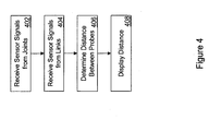
- FIG. 4 is a flowchart illustrating a method of measuring a distance with one embodiment of the present invention.
- a processor receives signals from the joints or couplings of the device 402. These signals may comprise one or more angle measurements corresponding to the degree of rotation of a coupling or joint in one or more degrees of freedom. For example, if a coupling or joint is able to rotate in one degree of freedom, the joint sensor may generate a sensor signal comprising a measurement in degrees from a starting position.
- the processor also receives one or more sensor signals from the link or links in the metrology device 404. Since the link is expandable, the processor may receive measure corresponding to the over length of the link or to the amount of extension of the link. If the link is able to rotate, the link sensor may generate a signal corresponding to the rotation of the link from a starting position. For instance, the starting position may be when the ends of the link are aligned.
- the link may include a plurality of sensors.
- the links can report to the processor their geometric parameters via an electronic identification code stored on or derived from the link.
- the processor determines the distance between the probes at the two ends of the metrology device 406. In making the determination, the processor utilizes all of the joint and link sensor signals.
- the method for calculating the distance between ends of an articulated arm are well known to those of skill in the art and thus will not be described herein.
- the processor then causes the distance between the two ends to be displayed on a display 408.
- the display may be integral to the metrology device or may be contained within a remote device. In such an embodiment, the metrology device transmits the distance to the portable device, which then displays the measurement.
- Embodiments of the present invention may be utilized for a variety of applications. These applications include, for example, metrology, digitization, medical, manufacturing, and cartographic applications.
- a metrology device according to the present invention may be utilized to measure the inside or outside diameter of a component. Such measurements may be extremely difficult to take with current metrology devices or require special instruments designed to perform only the single specific measurement task.
- Embodiments of the present invention may also be utilized in the manufacturing context.
- an embodiment of the present invention may be utilized to measure components to be used in building a finished product.
- a metrology device that includes a fixed base; such embodiments may be utilized for guided tracing and tool placement by means of path planning and control software.
Landscapes
- Physics & Mathematics (AREA)
- General Physics & Mathematics (AREA)
- Length Measuring Devices With Unspecified Measuring Means (AREA)
- A Measuring Device Byusing Mechanical Method (AREA)
Applications Claiming Priority (2)
| Application Number | Priority Date | Filing Date | Title |
|---|---|---|---|
| US11/930,456 US7797849B2 (en) | 2007-10-31 | 2007-10-31 | Portable metrology device |
| PCT/US2008/072194 WO2009058452A1 (en) | 2007-10-31 | 2008-08-05 | Portable metrology device |
Publications (2)
| Publication Number | Publication Date |
|---|---|
| EP2205931A1 EP2205931A1 (en) | 2010-07-14 |
| EP2205931B1 true EP2205931B1 (en) | 2015-04-29 |
Family
ID=40042635
Family Applications (1)
| Application Number | Title | Priority Date | Filing Date |
|---|---|---|---|
| EP20080797171 Active EP2205931B1 (en) | 2007-10-31 | 2008-08-05 | Portable metrology device |
Country Status (7)
| Country | Link |
|---|---|
| US (2) | US7797849B2 (enExample) |
| EP (1) | EP2205931B1 (enExample) |
| JP (1) | JP5386497B2 (enExample) |
| KR (1) | KR101515667B1 (enExample) |
| CN (1) | CN101842659B (enExample) |
| CA (1) | CA2701891C (enExample) |
| WO (1) | WO2009058452A1 (enExample) |
Families Citing this family (31)
| Publication number | Priority date | Publication date | Assignee | Title |
|---|---|---|---|---|
| US7881896B2 (en) | 2002-02-14 | 2011-02-01 | Faro Technologies, Inc. | Portable coordinate measurement machine with integrated line laser scanner |
| GB0516276D0 (en) * | 2005-08-08 | 2005-09-14 | Crampton Stephen | Robust cmm arm with exoskeleton |
| US8066757B2 (en) | 2007-10-17 | 2011-11-29 | Mindframe, Inc. | Blood flow restoration and thrombus management methods |
| US7797849B2 (en) * | 2007-10-31 | 2010-09-21 | Immersion Corporation | Portable metrology device |
| US8122610B2 (en) * | 2008-03-28 | 2012-02-28 | Hexagon Metrology, Inc. | Systems and methods for improved coordination acquisition member comprising calibration information |
| US8240210B2 (en) * | 2009-02-18 | 2012-08-14 | General Electric Company | Method and system for multimodal inspection with a coordinate measuring device |
| US20110112786A1 (en) | 2009-11-06 | 2011-05-12 | Hexagon Metrology Ab | Cmm with improved sensors |
| US20110178765A1 (en) * | 2010-01-20 | 2011-07-21 | Faro Technologies, Inc. | Multi-functional coordinate measurement machines |
| USD643319S1 (en) | 2010-03-29 | 2011-08-16 | Hexagon Metrology Ab | Portable coordinate measurement machine |
| EP2381212B1 (en) * | 2010-04-26 | 2018-04-25 | Tesa Sa | Coordinate measuring system for rotationally symmetric workpieces |
| US8127458B1 (en) * | 2010-08-31 | 2012-03-06 | Hexagon Metrology, Inc. | Mounting apparatus for articulated arm laser scanner |
| US11314344B2 (en) * | 2010-12-03 | 2022-04-26 | Razer (Asia-Pacific) Pte. Ltd. | Haptic ecosystem |
| EP2508839B1 (de) * | 2011-04-07 | 2014-07-09 | Carl Mahr Holding GmbH | Messeinrichtung mit Sendeschaltung zur drahtlosen Übertragung eines Messwertsendesignals |
| DE102011119012A1 (de) * | 2011-11-16 | 2013-05-16 | Carl Zeiss Industrielle Messtechnik Gmbh | Vereinfachtes Koordinatenmesssystem für Schulungszwecke |
| US8763267B2 (en) | 2012-01-20 | 2014-07-01 | Hexagon Technology Center Gmbh | Locking counterbalance for a CMM |
| US8881420B2 (en) | 2012-02-01 | 2014-11-11 | Randall Jeffrey COLOMBO | Method and apparatus for measuring an opening |
| JP6084364B2 (ja) | 2012-03-08 | 2017-02-22 | 株式会社ミツトヨ | 測定器 |
| US9069355B2 (en) | 2012-06-08 | 2015-06-30 | Hexagon Technology Center Gmbh | System and method for a wireless feature pack |
| US9163921B2 (en) | 2013-12-18 | 2015-10-20 | Hexagon Metrology, Inc. | Ultra-portable articulated arm coordinate measurement machine |
| US9594250B2 (en) | 2013-12-18 | 2017-03-14 | Hexagon Metrology, Inc. | Ultra-portable coordinate measurement machine |
| JP6381369B2 (ja) * | 2014-08-27 | 2018-08-29 | 株式会社ミツトヨ | 測定器 |
| WO2016069989A1 (en) | 2014-10-30 | 2016-05-06 | Intuitive Surgical Operations, Inc. | System and method for an articulated arm based tool guide |
| US10613629B2 (en) | 2015-03-27 | 2020-04-07 | Chad Laurendeau | System and method for force feedback interface devices |
| US10113852B2 (en) * | 2015-10-23 | 2018-10-30 | Body Shop Sano Co., Ltd. | Point-to-point distance gauge, point-to-point distance gauge system, and distortion measurement method using point-to-point distance gauge system |
| EP3184960B1 (en) * | 2015-12-22 | 2018-06-27 | Tesa Sa | Motorized orientable head for measuring system |
| GB2568459B (en) * | 2017-10-13 | 2020-03-18 | Renishaw Plc | Coordinate positioning machine |
| US10527397B2 (en) * | 2017-12-27 | 2020-01-07 | Mitutoyo Corporation | Cooperative measurement gauge system for multiple axis position measurement |
| GB2582972B (en) | 2019-04-12 | 2021-07-14 | Renishaw Plc | Coordinate positioning machine |
| US11231263B2 (en) * | 2019-08-02 | 2022-01-25 | Faro Technologies, Inc. | Wearable coordinate measurement devices |
| CN114353693B (zh) * | 2021-12-28 | 2023-11-28 | 中国航空工业集团公司北京长城航空测控技术研究所 | 一种大尺度三维空间整体测量定位仪专用手持矢量杆 |
| US11747126B1 (en) * | 2022-05-20 | 2023-09-05 | Sa08700334 | Ultra-light and ultra-accurate portable coordinate measurement machine with reduced profile swivel joints |
Family Cites Families (36)
| Publication number | Priority date | Publication date | Assignee | Title |
|---|---|---|---|---|
| US541749A (en) * | 1895-06-25 | George harris | ||
| US658011A (en) * | 1899-12-11 | 1900-09-18 | Lake Boreland W | Combined compasses and calipers. |
| US2906179A (en) * | 1957-01-28 | 1959-09-29 | North American Aviation Inc | Vector gage |
| US4437241A (en) * | 1979-08-22 | 1984-03-20 | Lemelson Jerome H | Measuring instrument and method |
| US5337488A (en) * | 1979-08-22 | 1994-08-16 | Lemelson Jerome H | Measuring instrument and method |
| US4468860A (en) * | 1982-03-08 | 1984-09-04 | Rodengen Jeffrey L | Measuring device |
| CA1299362C (en) * | 1986-12-10 | 1992-04-28 | Gregory James Mcdonald | Coordinate measuring system |
| JP2610634B2 (ja) * | 1988-01-13 | 1997-05-14 | 株式会社アマダ | 板材の二枚取検出装置 |
| JPH07100289B2 (ja) * | 1989-01-18 | 1995-11-01 | 株式会社トプコン | 玉摺機のレンズ加工可否判定装置 |
| US5144823A (en) * | 1991-03-05 | 1992-09-08 | Robert Gene Smith | Bend angle indicator |
| GB9108497D0 (en) | 1991-04-20 | 1991-06-05 | Ind Limited W | Human/computer interface |
| US5313713A (en) * | 1992-08-14 | 1994-05-24 | Zircon Corporation | Electronic level with display scale and audible tone scale |
| US6535794B1 (en) * | 1993-02-23 | 2003-03-18 | Faro Technologoies Inc. | Method of generating an error map for calibration of a robot or multi-axis machining center |
| WO1995002801A1 (en) | 1993-07-16 | 1995-01-26 | Immersion Human Interface | Three-dimensional mechanical mouse |
| US5724264A (en) * | 1993-07-16 | 1998-03-03 | Immersion Human Interface Corp. | Method and apparatus for tracking the position and orientation of a stylus and for digitizing a 3-D object |
| WO1995020787A1 (en) | 1994-01-27 | 1995-08-03 | Exos, Inc. | Multimode feedback display technology |
| US5488779A (en) * | 1994-08-12 | 1996-02-06 | Zircon Corporation | Electronic level with stereo sound indication |
| US6366830B2 (en) * | 1995-07-10 | 2002-04-02 | Newport Corporation | Self-teaching robot arm position method to compensate for support structure component alignment offset |
| US5740881A (en) * | 1996-09-06 | 1998-04-21 | Lensak; Michael | Safety device for detecting improper positioning of a ladder |
| WO1998021549A1 (en) * | 1996-11-11 | 1998-05-22 | Amada Company, Limited | Method and apparatus for measuring the dimensions of a sheet metal parts, and a sheet metal processing system which utilizes such measuring method and apparatus |
| AU2000255616A1 (en) * | 1999-07-08 | 2001-01-30 | David Arlinsky | Measuring device, and method for programming a soft feature key of an electronic device |
| DE10051870A1 (de) * | 1999-12-08 | 2001-07-12 | Busch Dieter & Co Prueftech | Ergonomisch gestaltete, störsignalreduzierende Lagemesssonde zum gegenseitigen Ausrichten von Körpern |
| US6694636B1 (en) * | 2000-09-01 | 2004-02-24 | Kevin Maher | Electrocardiogram compass |
| US6890312B1 (en) * | 2001-12-03 | 2005-05-10 | William B. Priester | Joint angle indication system |
| US7027031B2 (en) * | 2002-02-07 | 2006-04-11 | Gifu University | Touch sense interface and method for controlling touch sense interface |
| CN100523709C (zh) * | 2002-02-14 | 2009-08-05 | Faro科技有限公司 | 带有铰接臂的便携式坐标测量机 |
| ES2212726B1 (es) | 2002-07-29 | 2005-10-16 | Idiada Automotive Techonology,S.A | Dispositivo de medicion dinamica de la posicion relativa de un objeto-. |
| US6817108B2 (en) * | 2003-02-05 | 2004-11-16 | Homer L. Eaton | Articulation measuring arm having rotatable part-carrying platen |
| JP4707306B2 (ja) * | 2003-02-28 | 2011-06-22 | 株式会社小坂研究所 | 多関節型座標測定装置 |
| DE10313912B4 (de) | 2003-03-27 | 2007-07-12 | Keller Grundbau Gmbh | Vorrichtung zum Bestimmen des Durchmessers bzw. Radius von Hohlräumen |
| US6836972B2 (en) * | 2003-04-01 | 2005-01-04 | Lisa Drahos | Electronic level with audible and visual indicators |
| GB2417090A (en) * | 2003-04-28 | 2006-02-15 | Stephen James Crampton | CMM arm with exoskeleton |
| FR2861843B1 (fr) * | 2003-10-29 | 2006-07-07 | Romain Granger | Dispositif de connexion associe a un bras d'appareil de mesure tridimentionnelle a bras articules |
| CN2840048Y (zh) * | 2005-07-05 | 2006-11-22 | 技鼎股份有限公司 | 模组化探针装置及探针 |
| GB2429254A (en) | 2005-08-18 | 2007-02-21 | Profile Internat Ltd | Pig for inspecting pipelines internally |
| US7797849B2 (en) * | 2007-10-31 | 2010-09-21 | Immersion Corporation | Portable metrology device |
-
2007
- 2007-10-31 US US11/930,456 patent/US7797849B2/en not_active Expired - Fee Related
-
2008
- 2008-08-05 KR KR1020107011978A patent/KR101515667B1/ko not_active Expired - Fee Related
- 2008-08-05 JP JP2010532095A patent/JP5386497B2/ja not_active Expired - Fee Related
- 2008-08-05 CA CA2701891A patent/CA2701891C/en not_active Expired - Fee Related
- 2008-08-05 EP EP20080797171 patent/EP2205931B1/en active Active
- 2008-08-05 WO PCT/US2008/072194 patent/WO2009058452A1/en not_active Ceased
- 2008-08-05 CN CN2008801138740A patent/CN101842659B/zh not_active Expired - Fee Related
-
2010
- 2010-09-16 US US12/883,760 patent/US8028431B2/en not_active Expired - Fee Related
Also Published As
| Publication number | Publication date |
|---|---|
| JP2011504226A (ja) | 2011-02-03 |
| JP5386497B2 (ja) | 2014-01-15 |
| CA2701891A1 (en) | 2009-05-07 |
| US20110010957A1 (en) | 2011-01-20 |
| EP2205931A1 (en) | 2010-07-14 |
| US7797849B2 (en) | 2010-09-21 |
| WO2009058452A1 (en) | 2009-05-07 |
| CN101842659A (zh) | 2010-09-22 |
| CA2701891C (en) | 2013-04-23 |
| US8028431B2 (en) | 2011-10-04 |
| KR20100098518A (ko) | 2010-09-07 |
| CN101842659B (zh) | 2013-09-11 |
| US20090106994A1 (en) | 2009-04-30 |
| KR101515667B1 (ko) | 2015-04-27 |
Similar Documents
| Publication | Publication Date | Title |
|---|---|---|
| CA2701891C (en) | Portable metrology device | |
| AU2009227956B2 (en) | Tracking system and method | |
| TWI693923B (zh) | 醫療手術導航方法及機器人系統 | |
| US9115998B2 (en) | Tracking system and method | |
| CN107209003B (zh) | 用于机器人校准和监测的激光测量仪 | |
| EP1893942B1 (en) | Apparatus and method for relocating an articulating-arm coordinate measuring machine | |
| JP5378374B2 (ja) | リアルオブジェクトに対するカメラの位置および方向を把握する方法およびシステム | |
| EP2418562B1 (en) | Modelling of hand and arm position and orientation | |
| US20060127836A1 (en) | Tooth movement tracking system | |
| US20140206990A1 (en) | CT View Window | |
| EP2636987A1 (en) | An apparatus for pointing spatial coordinates, comprising a movable hand-held probe and a portable base unit, and a related method | |
| WO2009086495A3 (en) | Robotic arm for accurate positioning in three-dimensional space, measurement of three-dimensional coordinates, and remote tooling operations in three-dimensional space | |
| CN103797512A (zh) | 机器人与图像之间的自动联机配准 | |
| CN109282774B (zh) | 一种基于距离测量求解球关节三自由度姿态的装置及方法 | |
| Kabuye et al. | Tracking of scalpel motions with an inertial measurement unit system | |
| US8942785B2 (en) | Selectable orientation bent tip calibration-free probe | |
| Huang | Kinematic calibration for da vinci surgical robot | |
| CN115281850B (zh) | 基于半球激光列表法的器具姿态评价方法 | |
| JP4259910B2 (ja) | ロボットの教示方法および教示装置 | |
| JP2011056070A (ja) | 手術ナビゲーションシステム及びこれに用いる磁気センサ装着具 | |
| Li et al. | A Novel Shape Estimation Strategy for Continuum Robots Using Multiple Hall-Effect Sensors and IMUs | |
| JP2006167845A (ja) | マスタ・スレーブ型遠隔操作システム | |
| Ouellet Delorme | Method for the characterisation and feasibility study of a six degree-of-freedom electromagnetic tracking system |
Legal Events
| Date | Code | Title | Description |
|---|---|---|---|
| PUAI | Public reference made under article 153(3) epc to a published international application that has entered the european phase |
Free format text: ORIGINAL CODE: 0009012 |
|
| 17P | Request for examination filed |
Effective date: 20100331 |
|
| AK | Designated contracting states |
Kind code of ref document: A1 Designated state(s): AT BE BG CH CY CZ DE DK EE ES FI FR GB GR HR HU IE IS IT LI LT LU LV MC MT NL NO PL PT RO SE SI SK TR |
|
| AX | Request for extension of the european patent |
Extension state: AL BA MK RS |
|
| RIN1 | Information on inventor provided before grant (corrected) |
Inventor name: STEGER, RYAN Inventor name: GOMEZ, DANIEL, H. |
|
| RAP1 | Party data changed (applicant data changed or rights of an application transferred) |
Owner name: IMMERSION CORPORATION |
|
| 17Q | First examination report despatched |
Effective date: 20131108 |
|
| GRAP | Despatch of communication of intention to grant a patent |
Free format text: ORIGINAL CODE: EPIDOSNIGR1 |
|
| INTG | Intention to grant announced |
Effective date: 20141124 |
|
| GRAS | Grant fee paid |
Free format text: ORIGINAL CODE: EPIDOSNIGR3 |
|
| GRAA | (expected) grant |
Free format text: ORIGINAL CODE: 0009210 |
|
| AK | Designated contracting states |
Kind code of ref document: B1 Designated state(s): AT BE BG CH CY CZ DE DK EE ES FI FR GB GR HR HU IE IS IT LI LT LU LV MC MT NL NO PL PT RO SE SI SK TR |
|
| AX | Request for extension of the european patent |
Extension state: AL BA MK RS |
|
| REG | Reference to a national code |
Ref country code: GB Ref legal event code: FG4D |
|
| REG | Reference to a national code |
Ref country code: CH Ref legal event code: EP |
|
| REG | Reference to a national code |
Ref country code: AT Ref legal event code: REF Ref document number: 724678 Country of ref document: AT Kind code of ref document: T Effective date: 20150515 |
|
| REG | Reference to a national code |
Ref country code: IE Ref legal event code: FG4D |
|
| REG | Reference to a national code |
Ref country code: DE Ref legal event code: R096 Ref document number: 602008037946 Country of ref document: DE Effective date: 20150611 |
|
| REG | Reference to a national code |
Ref country code: FR Ref legal event code: PLFP Year of fee payment: 8 |
|
| REG | Reference to a national code |
Ref country code: NL Ref legal event code: VDEP Effective date: 20150429 |
|
| REG | Reference to a national code |
Ref country code: AT Ref legal event code: MK05 Ref document number: 724678 Country of ref document: AT Kind code of ref document: T Effective date: 20150429 |
|
| REG | Reference to a national code |
Ref country code: LT Ref legal event code: MG4D |
|
| PG25 | Lapsed in a contracting state [announced via postgrant information from national office to epo] |
Ref country code: NL Free format text: LAPSE BECAUSE OF FAILURE TO SUBMIT A TRANSLATION OF THE DESCRIPTION OR TO PAY THE FEE WITHIN THE PRESCRIBED TIME-LIMIT Effective date: 20150429 |
|
| PG25 | Lapsed in a contracting state [announced via postgrant information from national office to epo] |
Ref country code: LT Free format text: LAPSE BECAUSE OF FAILURE TO SUBMIT A TRANSLATION OF THE DESCRIPTION OR TO PAY THE FEE WITHIN THE PRESCRIBED TIME-LIMIT Effective date: 20150429 Ref country code: PT Free format text: LAPSE BECAUSE OF FAILURE TO SUBMIT A TRANSLATION OF THE DESCRIPTION OR TO PAY THE FEE WITHIN THE PRESCRIBED TIME-LIMIT Effective date: 20150831 Ref country code: FI Free format text: LAPSE BECAUSE OF FAILURE TO SUBMIT A TRANSLATION OF THE DESCRIPTION OR TO PAY THE FEE WITHIN THE PRESCRIBED TIME-LIMIT Effective date: 20150429 Ref country code: NO Free format text: LAPSE BECAUSE OF FAILURE TO SUBMIT A TRANSLATION OF THE DESCRIPTION OR TO PAY THE FEE WITHIN THE PRESCRIBED TIME-LIMIT Effective date: 20150729 Ref country code: ES Free format text: LAPSE BECAUSE OF FAILURE TO SUBMIT A TRANSLATION OF THE DESCRIPTION OR TO PAY THE FEE WITHIN THE PRESCRIBED TIME-LIMIT Effective date: 20150429 Ref country code: HR Free format text: LAPSE BECAUSE OF FAILURE TO SUBMIT A TRANSLATION OF THE DESCRIPTION OR TO PAY THE FEE WITHIN THE PRESCRIBED TIME-LIMIT Effective date: 20150429 |
|
| PG25 | Lapsed in a contracting state [announced via postgrant information from national office to epo] |
Ref country code: AT Free format text: LAPSE BECAUSE OF FAILURE TO SUBMIT A TRANSLATION OF THE DESCRIPTION OR TO PAY THE FEE WITHIN THE PRESCRIBED TIME-LIMIT Effective date: 20150429 Ref country code: GR Free format text: LAPSE BECAUSE OF FAILURE TO SUBMIT A TRANSLATION OF THE DESCRIPTION OR TO PAY THE FEE WITHIN THE PRESCRIBED TIME-LIMIT Effective date: 20150730 Ref country code: LV Free format text: LAPSE BECAUSE OF FAILURE TO SUBMIT A TRANSLATION OF THE DESCRIPTION OR TO PAY THE FEE WITHIN THE PRESCRIBED TIME-LIMIT Effective date: 20150429 Ref country code: IS Free format text: LAPSE BECAUSE OF FAILURE TO SUBMIT A TRANSLATION OF THE DESCRIPTION OR TO PAY THE FEE WITHIN THE PRESCRIBED TIME-LIMIT Effective date: 20150829 |
|
| PG25 | Lapsed in a contracting state [announced via postgrant information from national office to epo] |
Ref country code: EE Free format text: LAPSE BECAUSE OF FAILURE TO SUBMIT A TRANSLATION OF THE DESCRIPTION OR TO PAY THE FEE WITHIN THE PRESCRIBED TIME-LIMIT Effective date: 20150429 Ref country code: DK Free format text: LAPSE BECAUSE OF FAILURE TO SUBMIT A TRANSLATION OF THE DESCRIPTION OR TO PAY THE FEE WITHIN THE PRESCRIBED TIME-LIMIT Effective date: 20150429 |
|
| REG | Reference to a national code |
Ref country code: DE Ref legal event code: R097 Ref document number: 602008037946 Country of ref document: DE |
|
| PG25 | Lapsed in a contracting state [announced via postgrant information from national office to epo] |
Ref country code: SK Free format text: LAPSE BECAUSE OF FAILURE TO SUBMIT A TRANSLATION OF THE DESCRIPTION OR TO PAY THE FEE WITHIN THE PRESCRIBED TIME-LIMIT Effective date: 20150429 Ref country code: PL Free format text: LAPSE BECAUSE OF FAILURE TO SUBMIT A TRANSLATION OF THE DESCRIPTION OR TO PAY THE FEE WITHIN THE PRESCRIBED TIME-LIMIT Effective date: 20150429 Ref country code: CZ Free format text: LAPSE BECAUSE OF FAILURE TO SUBMIT A TRANSLATION OF THE DESCRIPTION OR TO PAY THE FEE WITHIN THE PRESCRIBED TIME-LIMIT Effective date: 20150429 Ref country code: RO Free format text: LAPSE BECAUSE OF NON-PAYMENT OF DUE FEES Effective date: 20150429 |
|
| PLBE | No opposition filed within time limit |
Free format text: ORIGINAL CODE: 0009261 |
|
| STAA | Information on the status of an ep patent application or granted ep patent |
Free format text: STATUS: NO OPPOSITION FILED WITHIN TIME LIMIT |
|
| PG25 | Lapsed in a contracting state [announced via postgrant information from national office to epo] |
Ref country code: LU Free format text: LAPSE BECAUSE OF FAILURE TO SUBMIT A TRANSLATION OF THE DESCRIPTION OR TO PAY THE FEE WITHIN THE PRESCRIBED TIME-LIMIT Effective date: 20150805 Ref country code: MC Free format text: LAPSE BECAUSE OF FAILURE TO SUBMIT A TRANSLATION OF THE DESCRIPTION OR TO PAY THE FEE WITHIN THE PRESCRIBED TIME-LIMIT Effective date: 20150429 |
|
| REG | Reference to a national code |
Ref country code: CH Ref legal event code: PL |
|
| 26N | No opposition filed |
Effective date: 20160201 |
|
| PG25 | Lapsed in a contracting state [announced via postgrant information from national office to epo] |
Ref country code: IT Free format text: LAPSE BECAUSE OF FAILURE TO SUBMIT A TRANSLATION OF THE DESCRIPTION OR TO PAY THE FEE WITHIN THE PRESCRIBED TIME-LIMIT Effective date: 20150429 Ref country code: LI Free format text: LAPSE BECAUSE OF NON-PAYMENT OF DUE FEES Effective date: 20150831 Ref country code: CH Free format text: LAPSE BECAUSE OF NON-PAYMENT OF DUE FEES Effective date: 20150831 |
|
| PG25 | Lapsed in a contracting state [announced via postgrant information from national office to epo] |
Ref country code: SI Free format text: LAPSE BECAUSE OF FAILURE TO SUBMIT A TRANSLATION OF THE DESCRIPTION OR TO PAY THE FEE WITHIN THE PRESCRIBED TIME-LIMIT Effective date: 20150429 |
|
| REG | Reference to a national code |
Ref country code: IE Ref legal event code: MM4A |
|
| PG25 | Lapsed in a contracting state [announced via postgrant information from national office to epo] |
Ref country code: IE Free format text: LAPSE BECAUSE OF NON-PAYMENT OF DUE FEES Effective date: 20150805 |
|
| REG | Reference to a national code |
Ref country code: FR Ref legal event code: PLFP Year of fee payment: 9 |
|
| PG25 | Lapsed in a contracting state [announced via postgrant information from national office to epo] |
Ref country code: BE Free format text: LAPSE BECAUSE OF FAILURE TO SUBMIT A TRANSLATION OF THE DESCRIPTION OR TO PAY THE FEE WITHIN THE PRESCRIBED TIME-LIMIT Effective date: 20150429 |
|
| PG25 | Lapsed in a contracting state [announced via postgrant information from national office to epo] |
Ref country code: MT Free format text: LAPSE BECAUSE OF FAILURE TO SUBMIT A TRANSLATION OF THE DESCRIPTION OR TO PAY THE FEE WITHIN THE PRESCRIBED TIME-LIMIT Effective date: 20150429 |
|
| PG25 | Lapsed in a contracting state [announced via postgrant information from national office to epo] |
Ref country code: HU Free format text: LAPSE BECAUSE OF FAILURE TO SUBMIT A TRANSLATION OF THE DESCRIPTION OR TO PAY THE FEE WITHIN THE PRESCRIBED TIME-LIMIT; INVALID AB INITIO Effective date: 20080805 Ref country code: BG Free format text: LAPSE BECAUSE OF FAILURE TO SUBMIT A TRANSLATION OF THE DESCRIPTION OR TO PAY THE FEE WITHIN THE PRESCRIBED TIME-LIMIT Effective date: 20150429 |
|
| PG25 | Lapsed in a contracting state [announced via postgrant information from national office to epo] |
Ref country code: SE Free format text: LAPSE BECAUSE OF FAILURE TO SUBMIT A TRANSLATION OF THE DESCRIPTION OR TO PAY THE FEE WITHIN THE PRESCRIBED TIME-LIMIT Effective date: 20150429 Ref country code: CY Free format text: LAPSE BECAUSE OF FAILURE TO SUBMIT A TRANSLATION OF THE DESCRIPTION OR TO PAY THE FEE WITHIN THE PRESCRIBED TIME-LIMIT Effective date: 20150429 |
|
| REG | Reference to a national code |
Ref country code: FR Ref legal event code: PLFP Year of fee payment: 10 |
|
| PG25 | Lapsed in a contracting state [announced via postgrant information from national office to epo] |
Ref country code: TR Free format text: LAPSE BECAUSE OF FAILURE TO SUBMIT A TRANSLATION OF THE DESCRIPTION OR TO PAY THE FEE WITHIN THE PRESCRIBED TIME-LIMIT Effective date: 20150429 |
|
| REG | Reference to a national code |
Ref country code: FR Ref legal event code: PLFP Year of fee payment: 11 |
|
| PGFP | Annual fee paid to national office [announced via postgrant information from national office to epo] |
Ref country code: DE Payment date: 20190828 Year of fee payment: 12 Ref country code: FR Payment date: 20190826 Year of fee payment: 12 |
|
| PGFP | Annual fee paid to national office [announced via postgrant information from national office to epo] |
Ref country code: GB Payment date: 20190827 Year of fee payment: 12 |
|
| REG | Reference to a national code |
Ref country code: DE Ref legal event code: R119 Ref document number: 602008037946 Country of ref document: DE |
|
| GBPC | Gb: european patent ceased through non-payment of renewal fee |
Effective date: 20200805 |
|
| PG25 | Lapsed in a contracting state [announced via postgrant information from national office to epo] |
Ref country code: FR Free format text: LAPSE BECAUSE OF NON-PAYMENT OF DUE FEES Effective date: 20200831 Ref country code: DE Free format text: LAPSE BECAUSE OF NON-PAYMENT OF DUE FEES Effective date: 20210302 |
|
| PG25 | Lapsed in a contracting state [announced via postgrant information from national office to epo] |
Ref country code: GB Free format text: LAPSE BECAUSE OF NON-PAYMENT OF DUE FEES Effective date: 20200805 |