EP2205809B1 - Self-contained lifting device for the mobile bottom of a swimming pool - Google Patents
Self-contained lifting device for the mobile bottom of a swimming pool Download PDFInfo
- Publication number
- EP2205809B1 EP2205809B1 EP08835415A EP08835415A EP2205809B1 EP 2205809 B1 EP2205809 B1 EP 2205809B1 EP 08835415 A EP08835415 A EP 08835415A EP 08835415 A EP08835415 A EP 08835415A EP 2205809 B1 EP2205809 B1 EP 2205809B1
- Authority
- EP
- European Patent Office
- Prior art keywords
- lifting
- mobile
- swimming pool
- pool
- mobile bottom
- Prior art date
- Legal status (The legal status is an assumption and is not a legal conclusion. Google has not performed a legal analysis and makes no representation as to the accuracy of the status listed.)
- Not-in-force
Links
Images


Classifications
-
- E—FIXED CONSTRUCTIONS
- E04—BUILDING
- E04H—BUILDINGS OR LIKE STRUCTURES FOR PARTICULAR PURPOSES; SWIMMING OR SPLASH BATHS OR POOLS; MASTS; FENCING; TENTS OR CANOPIES, IN GENERAL
- E04H4/00—Swimming or splash baths or pools
- E04H4/06—Safety devices; Coverings for baths
- E04H4/065—Floors adjustable in height
Definitions
- this type of mobile bottom device has, according to the systems, certain technical drawbacks, for example the fact that the bottom of the pond is occupied with a large volume between the mobile bottom and the bottom of the basin, for the localization and the implementation. submerged mechanisms. In such a case, the useful depth of the pool is substantially reduced.
- pool pools have an inclined bottom to offer bathers, a shallow pool at one end (small pool) and a deeper pool at the other end (large pool).
- the rigidity of the moving floor is a major safety factor. Indeed, depending on the location of the fall of the body on the mobile bottom, it can deform locally and sufficiently to allow the body to pass under the mobile bottom, causing and almost inevitably drowning.
- the regulations in force define precisely the dimensions of a peripheral space between the edge of the movable bottom and the walls of the basin.
- This space has the main purpose of facilitating the movement of water during movement of the movable floor in the basin while prohibiting accidents that could be caused by the engagement of the foot of a bather in this space.
- the limitation of the number of lifting points is most often due to the complexity of the devices set up to act simultaneously on said lifting points. This complexity of the kinematics implemented is even greater than the number of lifting points of the moving floor is high.
- Similar devices also combine the integration of jacks and cable networks and pulleys in the structure of the mobile bottom, which adds to the drawbacks mentioned above that of the immersion of mechanical components active in a chlorinated aquatic environment.
- the present invention aims to provide a significant improvement in the operating elements of a movable floor inside a pool and thus significantly reduce the involvement of accessories, amenities and work in the construction of a pool and consequently reduce the cost.
- the autonomous lifting module according to the invention is of great structural simplicity, unlike many devices of the state of the art which have a single central drive unit acting on several lifting points via complex installations and bulky mechanisms (many cables, pulleys, cylinders, levers etc.), which involves heavy work and development in the basin and out of the basin and as a result of the high costs and installation time.
- the autonomous lifting module according to the invention is arranged in as many units as necessary all around and outside a swimming pool, to allow total immersion and lifting of a movable floor.
- the different lifting modules installed around the pool are exactly the same. They can be controlled independently of each other. By simple adjustments after installation, it is sufficient to synchronize the different autonomous lifting modules to achieve the desired cooperation.
- the device of the present invention considerably reduces the risk of breakdowns, maintenance and repair operations. It is suitable for all types of hard-walled pools, all forms of pools and basins. It does not strike the water volume of the pond and can be implemented with all types of mobile funds.
- the mobile bottom Before the manufacture of a swimming pool, the mobile bottom is studied in accordance with the regulations in force and the characteristics of the basin, such as the shape, the dimensions, the depth, the base of the bottom and the accesses. The amount and location of the lifting points is determined according to the characteristics of the moving bottom to be moved.
- the drive unit comprises a motor driven by electrical energy, connected to the transmission element by drive means such as a set of pulleys or accessories or means of reduction, so as to generate the immersion or lifting of the mobile bottom in the pool of the pool.
- the drive unit comprises a motor driven by hydraulic energy, connected to the transmission element by driving means such as a set of pulleys or accessories, so to generate the immersion or the raising of the mobile bottom in the basin of the swimming pool.
- Such an engine offers a power and a torque of operation perfectly adapted to this use. It also eliminates a braking system preventing the movement of the moving bottom.
- the guide element is a rail having the general shape of a profile disposed substantially vertically along a vertical wall delimiting the swimming pool basin, the movable floor being provided with sliding means and / or peripheral rolling cooperating bearing on one side of the rail.
- the guide element is suspended at its upper end by a fixing plate mounted on an upper edge of the swimming pool, constituted in particular by a structural element and / or a lip .
- the guide element has no attachment to the vertical wall against which it is arranged.
- the guide element is made of stainless material and comprises a foam coating on one face facing the vertical wall, so as to ensure a non-contact aggressive with the latter.
- the section of the guide element has a corrugated shape provided with a central recess cooperating with the sliding and / or rolling means of the movable bottom, the recess being bordered by side bosses guiding the movable bottom into the recess.
- the transmission element consists of a "marine" type strap.
- a return roller is arranged in the upper part of the guide element and / or on the mounting plate, the transmission element connecting the drive housing to the lifting point rolling on the return roller.
- the subject of the invention is also a lifting device for mobile swimming pool rigid bottom, comprising a plurality of lifting modules having all or some of the preceding characteristics, the lifting modules being arranged at several lifting points distinct from the moving bottom, distributed at the periphery of the latter.
- the installation comprises a device for adjusting and synchronizing the operation of the various lifting modules.
- the adjusting and synchronizing device is adapted to generate different lifting or immersion strokes for the respective lifting points of the movable floor, so that the latter can be plated. on the bottom of the pool and this regardless of the angle of inclination of the bottom plate of the pool.
- the invention furthermore relates to a swimming pool comprising a movable rigid bottom, as well as a mobile bottom lift installation having all or some of the preceding features, at least one drive housing being mounted on an upper edge of the pool , such as a structural element and / or a lip, prominently with respect to this upper edge.
- the swimming pool comprises a mobile bottom lifting installation having all or some of the preceding characteristics, at least one drive housing being mounted externally to an upper edge of the pool, so that at least a portion of the drive housing is buried in the ground substantially flush with said upper edge.
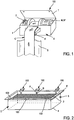
- FIG. 1 the main elements constituting a lifting module 100 according to the invention.
- the latter comprises a drive unit A controlling the immersion movements (in the direction of descent) and lifting of the moving base 3.
- the lifting module 100 also comprises a guide element B of a peripheral zone of the moving base 3
- the lifting module 100 further comprises a transmission element C connected on the one hand to the drive housing A and on the other hand to the moving bottom 3.
- the lifting module 100 acts at a single point of lifting.
- the concept of "lifting point” means a zone restricted to the periphery of the movable floor 3, of the order of a few centimeters or decimetres.
- the transmission element C is therefore connected to the moving bottom 3 at a single lifting point.
- An immersion (or descent) or lifting movement is imparted to the moving bottom 3 by a set of lifting modules 100 which are arranged in as many units as necessary on the edges of the Pool D of the pool.
- the figure 2 illustrates the implantation of six lifting modules 100 acting at six lifting point of the movable base 3.
- the number and distribution of the lifting modules are a function of the load to be supported and driven, which depends directly on the weight of the moving floor 3 but also the shape of the movable bottom 3. It is important to aim for a balanced distribution and the most homogeneous possible efforts to support each of the lifting modules 100.
- the lifting modules 100 of the installation are activated by an adjustment and synchronization device.
- the latter is adapted to control lifting strokes that may be similar or different at each lifting point.
- the various modules 100 can control the displacement of the mobile base 3 while keeping it substantially horizontal regardless of its height.
- the various modules 100 can control the displacement of the mobile base 3 by tilting it to a desired angle, for example so as to fit a bottom of the pool which would itself be inclined with respect to a horizontal plane.
- the drive housing A comprises a motor M, M 'connected to the transmission element C. This connection is provided by drive means (not shown) such as a set of pulleys or accessories or reduction means which are classic and of a design perfectly within the reach of the skilled person.
- the motor M is a motor driven by electrical energy.
- the motor is connected to a standard electrical circuit and complies with the rules in force for the supply of power to outdoor equipment.
- a climbing speed of 0.03 m / s, a pulley radius of 0.05 m at the motor shaft output, a linear acceleration of 1m / s 2 , a yield of 0.6 and a lifting distance of 2.5 m we obtain a necessary mechanical power of the order of 75 W for a nominal torque of 125 Nm.
- four electric motors we divide by four the power necessary for each one.
- the motor M ' is driven by hydraulic energy.
- a hydraulic motor also dispenses to provide braking means capable of blocking the displacement of the movable base 3.
- a hydraulic motor motor pump unit
- Each motor is hydraulically independent and has its own supply of fluid. Only one power supply is to be routed to drive unit A for the pump motor.
- a pump motor suitable for each module may be of the "CASAPPA Polaris 10 series pump” type.
- the developed torque (at 100 bar) is 1.35 Nm.
- the flow rate at 700 rpm is 0.68 l / min.
- the minimum operating speed is 650 rpm which implies the implementation of a reduction ratio of 132.
- the housing 1 constituting the drive housing A is made of a rigid material, strong enough to support the weight of one or two people leaning on it. This material is adapted to resist corrosion, by its chemical composition, or through a surface treatment.
- the drive housing A has on its upper part an access hatch T to install its components, but also to intervene directly in the mechanism for its troubleshooting or adjustment of operation.
- the drive housing A also encloses an indicator 2, preferably a visual indicator, which makes it possible to precisely identify, at the point of the lifting itself, the exact position of the moving base 3 with respect to the bottom 4 of the swimming pool.
- This positioning indicator 2 of the movable bottom 3 facilitates the adjustment and synchronization of the different lifting modules 100 between them.
- the mobile bottom 3 In the high position, called security, the mobile bottom 3 automatically finds and thanks to the settings a perfectly horizontal attitude.
- the guide member B is a rail having the general shape of a profile disposed substantially vertically along a vertical wall delimiting the basin D of the pool.
- the movable base 3 is provided with sliding and / or rolling means 6, typically balls (as illustrated in FIG. figure 6 ) or rollers held at the periphery of the movable bottom 3, cooperating in contact with the guide member B.
- the guide member B has a corrugated section. This section is provided with a central recess accommodating the sliding and / or rolling means 6, this central recess is bordered by lateral bosses channeling the sliding and / or rolling means 6 during their movement along the element. guidance. This corrugated shape is particularly suitable for optimal guidance of the moving floor, while being extremely simple to design and install.
- the guide member B is suspended by its upper end to a mounting plate 7. It is mounted on an upper edge of the pool, typically consisting of a structural element of the pool or a coping E.
- the fixation of the plate 7 on the structure or the lip E may be provided by fixing screws or by bonding or by any equivalent appropriate means.
- the guide element B is connected to the plate 7 by means that can be articulated, for example to allow easy packaging and transport (the platinum-guide element assembly being flat or folded on itself), and for a quick installation on the edge of the pool (the guide element B is positioned at 90 ° relative to the plate 7).
- the inclination at 90 ° between the plate 7 and the guide element B can be blocked by appropriate means, for example by a system of pins.
- the guide element B and the plate 7 can be automatically rigidly fixed at 90 ° to each other.
- the guide element B is devoid of attachment with a vertical wall 5 against which it is attached.
- the guide element B is simply oriented to fit this wall 5.
- the sliding and / or rolling means 6 only have the effect of abutting against the guiding element, which contributes to the plate against the wall 5 of the basin. It is not necessary to provide means for retaining the guide element.
- the guide element is made of stainless material, such as stainless steel.
- the guide element B may comprise on its face facing the wall 5, a coating or a layer 8 made of plastic, rubber or foam ( figure 3 ).
- the transmission element C connected to the engine M, M ' is also connected to the lifting point of the movable base 3 by appropriate attachment means, in order to transmit the traction forces to this lifting point.
- the transmission element C is a "marine" type strap, made of synthetic material, for example plastic or nylon or the like, particularly suitable for use in a chlorinated aquatic environment.
- a strap has extremely high tensile strength characteristics, for a relatively small thickness, which minimizes its bulk in the drive housing A when wound.
- the strap C is provided at each of its ends with an arrangement 13 allowing on the one hand its positioning and its anchoring on one of the internal drive elements to the drive housing A, and secondly its attachment to fastening means for connecting to the movable bottom 3.
- the strap C is provided with one or more inserts 14 intended to limit friction during the path along the guide element B.
- the drive housing A can be implanted in different ways.
- the housing A is mounted externally to an upper edge E of the pool, so that a lower part of the housing A is buried in the ground, set back relative to the basin D.
- the housing A is mounted over an outer edge E of the pool.
- the housing A can thus constitute in itself a stud from which one can dive into the pool.
- the housing A can also be integrated in a stud of this type.
- a return roller 9 may be provided at the junction of the plate 7 and the guide member B, so as to promote the rolling of the transmission element C which is to form a return angle in this area. In the same manner, it is possible to provide a return roller 9 'in other passage zones of the transmission element C, for example near the drive housing A ( figure 1 ).
- the sliding and / or rolling means typically balls in the illustrated example
- the sliding and / or rolling means can be mounted movably in a corresponding housing 10 formed at the periphery of the movable bottom 3, so as to make a clearance clearance between the wall
- the ball is projecting about one-third of its diameter.
- a return spring 11 tends to push the ball towards the peripheral edge of the movable bottom 3.
- the imprisoning means 12 are located at the mouth of the housing 10 so as to prevent the ball from leaving its housing.
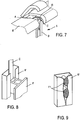
- FIG. figure 7 Another alternative embodiment of the drive housing A is also conceivable, as shown in FIG. figure 7 .
- the housing is located in a housing provided under the edge of the pool E.
- This mode of implementation requires a heavier adaptation of an existing pool (compared to the locations of figures 4 and 5 ), to receive the lifting module. It is also possible to provide visual cues on the rim E or nearby, so as to know precisely the location of drive boxes A concealed beneath the lip E.
- a lifting module according to the invention because of its simplicity, and the very principle of autonomy of the module, is perfectly suitable for installation on existing pool basins, the side walls of which are substantially vertical, without requiring any additional cost. equipment, excessive development.
- the transmission element may be a cable (not shown), replacing the strap, without calling into question other features of the invention.
- the rail B ' is attached and fixed to the wall of the basin D, for example by means of fixing screws, by gluing or by clipping means, which make it particularly removable .
- the section of the guide element B ' may have a general shape C, a central portion is contiguous to the wall 5 of the pool D pool.
- the opening of this section C along the entire length of the rail allows the displacement of the fastening means F, which secure the lower end of the transmission element C to the movable bottom 3, along the entire length of the rail .
- the guide element B ' may be entirely made of plastic, flexible or rigid, compatible with the chlorinated aquatic environment. With reference to the figure 9 this element may also comprise edges or lips delimiting the opening of the C, which are relatively flexible, so as to open during the passage of the attachment means F1, and to close by elasticity after their passage. This closing effect offers swimmers a smooth and non-aggressive surface.
- the body of the guide element may be made of a first, relatively rigid material, while the edges or lips of the opening of the C are made of a second, softer material allowing them to spacing and their closure under the solicitation of fastening means F1.
- the guide member B is positioned to be embedded or recessed in the inner wall 5 of the pond D.
- This arrangement provides flush surfaces of the guide member B" relative to the wall 5 of the basin, the guiding element particularly little aggressive for bather. This arrangement however supposes to provide for this integration of the guiding element as soon as the pool D is made.
Landscapes
- Engineering & Computer Science (AREA)
- Architecture (AREA)
- Civil Engineering (AREA)
- Structural Engineering (AREA)
- Devices For Medical Bathing And Washing (AREA)
- Invalid Beds And Related Equipment (AREA)
- Toys (AREA)
Abstract
Description
La législation relative à la sécurité à l'intérieur et dans l'environnement des piscines a fortement évolué au cours des dernières années, suscitant dans ce secteur professionnel l'avènement de nombreux accessoires, procédés ou dispositifs en charge de sécuriser l'approche des bassins ou encore alerter lors de la chute d'un corps dans l'eau.The legislation relating to indoor and outdoor swimming pool safety has evolved considerably in recent years, sparking in this professional sector the advent of numerous accessories, processes or devices in charge of securing the pool approach. or alert when a body falls into the water.
C'est ainsi qu'il est commun de rencontrer sur ce secteur de marché, divers modèles de barrières, murs ou rambardes conçues spécialement pour interdire aux enfants sans surveillance d'accéder seuls au bassin de la piscine. Ce moyen physique interdisant l'accès, n'assure pas toujours une totale sécurité, car la plupart du temps, il ne peut s'opposer efficacement à l'escalade et au franchissement.Thus, it is common to meet in this market sector, various models of barriers, walls or railings designed specifically to prohibit unattended children to access the pool alone. This physical means prohibiting access, does not always ensure total security, because most of the time, it can not effectively oppose escalation and crossing.
De nombreux autres dispositifs sont aujourd'hui disponibles dans le commerce, comme par exemple les alarmes sonores conçues pour signaler dans l'environnement proche du bassin, la chute d'un corps ou d'un objet dans l'eau. Ces dispositifs interviennent souvent, malheureusement, lorsque le mal est fait, c'est-à-dire lorsque l'enfant est tombé dans l'eau et qu'il est déjà en situation de détresse. La sauvegarde de l'intéressé dépend alors en premier lieu de la perception de l'alarme sonore par quelqu'un de son entourage, ce qui peut parfois être aléatoire lorsque d'autres bruits occupent l'environnement et en second lieu de la vitesse d'intervention, des personnes ayant perçu le signal d'alarme, qui peuvent être à ce moment précis très éloignées du bassin.Many other devices are now commercially available, such as sound alarms designed to signal in the vicinity of the basin, the fall of a body or an object in the water. These devices often occur, unfortunately, when the harm is done, that is to say when the child has fallen into the water and is already in distress. The safeguarding of the person concerned then depends primarily on the perception of the sound alarm by someone around him, which can sometimes be random when other noises occupy the environment and secondly the speed of intervention, people who have perceived the alarm signal, who may be at this very moment very far from the basin.
Certains professionnels proposent alors divers dispositifs permettant de recouvrir totalement la surface de l'eau en dehors des heures de baignade, en déroulant ou en faisant coulisser un écran protecteur carrément en contact avec l'eau ou très légèrement au-dessus de celle-ci. On se référera par exemple aux documents
Si ce genre de procédé semble très efficace pour éviter la chute dans l'eau de feuilles et autres déchets végétaux légers, la rigidité de l'écran déroulé ou déplié est souvent insuffisante pour retenir suffisamment longtemps le corps d'un enfant tombé accidentellement dans le bassin.If this kind of process seems very effective to prevent the drop in water of leaves and other light vegetable waste, the rigidity of the screen unrolled or unfolded is often insufficient to hold the body of a child accidentally fallen into the pelvis long enough.
A ce jour, il semble que le plus efficace des systèmes de sécurité pour piscine soit la présence d'un fond rigide mobile qui, totalement immergé au plus profond du bassin au moment de la baignade, est relevé en fin de baignade pour venir couvrir toute la surface de la piscine, offrant ainsi une sécurité totale par une rigidité et une résistance à la chute particulièrement adaptées.To date, it seems that the most effective swimming pool safety system is the presence of a mobile hard bottom which, fully submerged deep in the pool at the time of swimming, is raised at the end of swimming to cover all the surface of the pool, thus offering total safety by rigidity and resistance to the fall particularly adapted.
Néanmoins, ce genre de dispositif de fond mobile présente selon les systèmes certains inconvénients techniques comme par exemple, l'occupation en fond de bassin d'un volume important entre le fond mobile et le fond du bassin, pour la localisation et la mise en oeuvre de mécanismes immergés. Dans un tel cas, la profondeur utile du bassin de la piscine est sensiblement réduit.Nevertheless, this type of mobile bottom device has, according to the systems, certain technical drawbacks, for example the fact that the bottom of the pond is occupied with a large volume between the mobile bottom and the bottom of the basin, for the localization and the implementation. submerged mechanisms. In such a case, the useful depth of the pool is substantially reduced.
D'autre part, de nombreux bassins de piscines présentent un fond incliné pour offrir aux baigneurs, un bassin peu profond à une extrémité (petit bassin) et un bassin plus profond à l'autre extrémité (grand bassin).On the other hand, many pool pools have an inclined bottom to offer bathers, a shallow pool at one end (small pool) and a deeper pool at the other end (large pool).
La rigidité du fond mobile est dans ce procédé un facteur de sécurité majeur. En effet, selon l'endroit de la chute du corps sur le fond mobile, celui-ci peut se déformer localement et suffisamment pour permettre au corps de passer sous le fond mobile, provoquant ainsi et quasi inévitablement la noyade.In this process, the rigidity of the moving floor is a major safety factor. Indeed, depending on the location of the fall of the body on the mobile bottom, it can deform locally and sufficiently to allow the body to pass under the mobile bottom, causing and almost inevitably drowning.
Plusieurs techniques ont été mises en oeuvre par les professionnels pour concilier la rigidité du fond mobile avec sa mobilité dans l'eau lors de la plongée ou du levage.Several techniques have been implemented by professionals to reconcile the rigidity of the mobile bottom with its mobility in the water during diving or lifting.
Le plus souvent, les fonds mobiles rencontrés dans le commerce ou l'état de la technique présentent des orifices facilitant le passage de l'eau au travers du fond mobile. Cet aménagement diminue sensiblement la résistance au déplacement et facilite la mobilité.Most often, mobile funds encountered in commerce or the state of the art have holes facilitating the passage of water through the movable floor. This arrangement substantially reduces the resistance to movement and facilitates mobility.
D'autre part, les règlements en vigueur définissent avec précision les dimensions d'un espace périphérique entre le bord du fond mobile et les parois du bassin. Cet espace a pour objet principal de faciliter les mouvements d'eau lors des déplacements du fond mobile dans le bassin tout en interdisant les accidents qui pourraient être provoqués par l'engagement du pied d'un baigneur dans cet espace.On the other hand, the regulations in force define precisely the dimensions of a peripheral space between the edge of the movable bottom and the walls of the basin. This space has the main purpose of facilitating the movement of water during movement of the movable floor in the basin while prohibiting accidents that could be caused by the engagement of the foot of a bather in this space.
Il apparaît donc que la sécurité maximum passe par la multiplication des points d'ancrage et de levage du fond mobile qui garantit une rigidité optimum et une bonne résistance à la chute d'un corps. Ce constat est d'autant plus vérifiable que la surface de la piscine est grande ou ses formes hors du commun.It therefore appears that the maximum safety passes through the multiplication of anchoring points and lifting of the movable bottom which guarantees optimum rigidity and good resistance to the fall of a body. This observation is even more verifiable that the surface of the pool is large or its forms out of the ordinary.
Pourtant l'état de la technique laisse apparaître le plus souvent des points de levage en nombre limité, comme par exemple quatre points de levage répartis aux quatre coins de la piscine lorsque celle-ci est de forme carrée ou rectangulaire.However, the state of the art reveals most often lifting points in limited numbers, such as four lifting points distributed at the four corners of the pool when it is square or rectangular.
La limitation du nombre de points de levage est le plus souvent due à la complexité des dispositifs mis en place pour agir simultanément sur les dits points de levage. Cette complexité des cinématiques mises en oeuvre est d'autant plus grande que le nombre de points de levage du fond mobile est élevé.The limitation of the number of lifting points is most often due to the complexity of the devices set up to act simultaneously on said lifting points. This complexity of the kinematics implemented is even greater than the number of lifting points of the moving floor is high.
Par exemple, on peut relever dans l'état de la technique des dispositifs agissant au moyen de vérins pneumatiques ou hydrauliques coopérant avec un jeu de câbles et poulies déployé tout autour de la piscine. Ce genre de dispositif à lourde cinématique implique des aménagements importants et coûteux, à l'intérieur, à l'extérieur et à proximité du bassin ce qui conduit inévitablement à de mauvais fonctionnements, pannes, interventions sur zones enterrées et consécutivement à l'élévation des coûts d'installation et de maintenance.For example, it can be noted in the state of the art devices acting by means of pneumatic or hydraulic cylinders cooperating with a set of cables and pulleys deployed around the pool. This type of heavy kinematic device involves significant and costly adjustments, inside, outside and near the basin which inevitably leads to malfunctions, breakdowns, interventions on buried zones and following the rise of installation and maintenance costs.
Des dispositifs similaires associent également l'intégration de vérins et réseaux de câbles et poulies dans la structure même du fond mobile, ce qui rajoute aux inconvénients précédemment cités celui de l'immersion de composants mécaniques actifs en milieu aquatique chloré.Similar devices also combine the integration of jacks and cable networks and pulleys in the structure of the mobile bottom, which adds to the drawbacks mentioned above that of the immersion of mechanical components active in a chlorinated aquatic environment.
Tous les dispositifs aujourd'hui présents dans l'état de la technique impliquent l'immersion de câbles métalliques dans l'eau, lesdits câbles étant actionnés au moyen de poulies traditionnelles enterrées à l'extérieur du bassin ou elles-mêmes immergées dans l'eau du bassin.All devices present today in the state of the art involve the immersion of metal cables in the water, said cables being actuated by means of traditional pulleys buried outside the basin or themselves immersed in the pond water.
La présente invention a pour but d'apporter une amélioration sensible des éléments de manoeuvre d'un fond mobile à l'intérieur d'un bassin et ainsi réduire considérablement l'implication d'accessoires, aménagements et travaux dans la construction d'une piscine et par voie de conséquence en diminuer le coût.The present invention aims to provide a significant improvement in the operating elements of a movable floor inside a pool and thus significantly reduce the involvement of accessories, amenities and work in the construction of a pool and consequently reduce the cost.
A cet effet, l'invention a pour objet un module de levage pour fond rigide mobile de piscine, caractérisé en ce qu'il comprend :
- a) un boîtier d'entraînement commandant les mouvements d'immersion et de levage en un point unique du fond mobile,
- b) au moins un élément de guidage périphérique du fond mobile,
- c) au moins un élément de transmission relié d'une part au boîtier d'entraînement, et d'autre part audit point unique du fond mobile,
- a) a drive box controlling the immersion and lifting movements at a single point of the moving bottom,
- b) at least one peripheral guide element of the movable floor,
- c) at least one transmission element connected on the one hand to the drive housing, and on the other hand to said single point of the moving base,
Ainsi le module autonome de levage selon l'invention est d'une grande simplicité structurelle, contrairement à de nombreux dispositifs de l'état de la technique qui présentent une seule unité centrale d'entraînement agissant sur plusieurs points de levage par l'intermédiaire d'installations complexes et de mécanismes encombrants (nombreux câbles, poulies, vérins, leviers etc.), technique qui implique de lourds travaux et aménagements dans le bassin et hors du bassin et en conséquence des coûts et temps d'installation élevés. Le module autonome de levage selon l'invention est disposé en autant d'unités que nécessaire tout autour et à l'extérieur d'un bassin de piscine, pour permettre l'immersion totale et le levage d'un fond mobile. Les différents modules de levage installés autour du bassin sont rigoureusement identiques. Ils peuvent être pilotés indépendamment les uns des autres. Il suffit par des réglages simples après installation de synchroniser les différents modules autonomes de levage pour parvenir à la coopération recherchée.Thus the autonomous lifting module according to the invention is of great structural simplicity, unlike many devices of the state of the art which have a single central drive unit acting on several lifting points via complex installations and bulky mechanisms (many cables, pulleys, cylinders, levers etc.), which involves heavy work and development in the basin and out of the basin and as a result of the high costs and installation time. The autonomous lifting module according to the invention is arranged in as many units as necessary all around and outside a swimming pool, to allow total immersion and lifting of a movable floor. The different lifting modules installed around the pool are exactly the same. They can be controlled independently of each other. By simple adjustments after installation, it is sufficient to synchronize the different autonomous lifting modules to achieve the desired cooperation.
En limitant et en simplifiant ses éléments actifs, le dispositif de la présente invention réduit considérablement les risques de pannes, les interventions de maintenance et de réparation. Il s'adapte à tous les types de piscines à parois rigides, toutes les formes de bassins et toutes les assiettes de fonds de bassins. Il ne grève pas le volume d'eau du bassin et peut être mis en oeuvre avec tous les types de fonds mobiles.By limiting and simplifying its active elements, the device of the present invention considerably reduces the risk of breakdowns, maintenance and repair operations. It is suitable for all types of hard-walled pools, all forms of pools and basins. It does not strike the water volume of the pond and can be implemented with all types of mobile funds.
Avant la fabrication d'une piscine, le fond mobile est étudié en conformité avec les règlements en vigueur et les caractéristiques du bassin, comme par exemple la forme, les dimensions, la profondeur, l'assiette du fond et les accès. La quantité et la localisation des points de levage sont déterminées en fonction des caractéristiques du fond mobile à mouvoir.Before the manufacture of a swimming pool, the mobile bottom is studied in accordance with the regulations in force and the characteristics of the basin, such as the shape, the dimensions, the depth, the base of the bottom and the accesses. The amount and location of the lifting points is determined according to the characteristics of the moving bottom to be moved.
Selon d'autres caractéristiques avantageuses de l'invention, le boîtier d'entraînement comprend un moteur animé par énergie électrique, relié à l'élément de transmission par des moyens d'entraînement tels qu'un jeu de poulies ou accessoires ou des moyens de réduction, de manière à générer l'immersion ou le relevage du fond mobile dans le bassin de la piscine.According to other advantageous features of the invention, the drive unit comprises a motor driven by electrical energy, connected to the transmission element by drive means such as a set of pulleys or accessories or means of reduction, so as to generate the immersion or lifting of the mobile bottom in the pool of the pool.
Selon encore d'autres caractéristiques avantageuses de l'invention, le boîtier d'entraînement comprend un moteur animé par énergie hydraulique, relié à l'élément de transmission par des moyens d'entraînement tels qu'un jeu de poulies ou accessoires, de manière à générer l'immersion ou le relevage du fond mobile dans le bassin de la piscine.According to still other advantageous features of the invention, the drive unit comprises a motor driven by hydraulic energy, connected to the transmission element by driving means such as a set of pulleys or accessories, so to generate the immersion or the raising of the mobile bottom in the basin of the swimming pool.
Un tel moteur offre une puissance et un couple de fonctionnement parfaitement adaptés à cet usage. Il permet en outre de s'affranchir d'un système de freinage empêchant le mouvement du fond mobile.Such an engine offers a power and a torque of operation perfectly adapted to this use. It also eliminates a braking system preventing the movement of the moving bottom.
Selon encore d'autres caractéristiques avantageuses de l'invention, l'élément de guidage est un rail ayant la forme générale d'un profilé disposé sensiblement verticalement le long d'une paroi verticale délimitant le bassin de la piscine, le fond mobile étant pourvu de moyens de glissement et/ou de roulement périphériques coopérant en appui sur une face du rail.According to still other advantageous features of the invention, the guide element is a rail having the general shape of a profile disposed substantially vertically along a vertical wall delimiting the swimming pool basin, the movable floor being provided with sliding means and / or peripheral rolling cooperating bearing on one side of the rail.
Selon encore d'autres caractéristiques avantageuses de l'invention, l'élément de guidage est suspendu à son extrémité supérieure par une platine de fixation montée sur un bord supérieur de la piscine, constitué en particulier par un élément de structure et/ou une margelle.According to still other advantageous features of the invention, the guide element is suspended at its upper end by a fixing plate mounted on an upper edge of the swimming pool, constituted in particular by a structural element and / or a lip .
Selon encore d'autres caractéristiques avantageuses de l'invention, l'élément de guidage est dépourvu de fixation sur la paroi verticale contre laquelle il est disposé.According to still other advantageous features of the invention, the guide element has no attachment to the vertical wall against which it is arranged.
Selon encore d'autres caractéristiques avantageuses de l'invention, l'élément de guidage est réalisé en matière inoxydable et comprend un revêtement de mousse sur une face en vis-à-vis de la paroi verticale, de manière à lui assurer un contact non agressif avec cette dernière.According to still other advantageous features of the invention, the guide element is made of stainless material and comprises a foam coating on one face facing the vertical wall, so as to ensure a non-contact aggressive with the latter.
Selon encore d'autres caractéristiques avantageuses de l'invention, la section de l'élément de guidage présente une forme ondulée pourvue d'un renfoncement central coopérant avec les moyens de glissement et/ou de roulement du fond mobile, le renfoncement étant bordé de bossages latéraux assurant le guidage du fond mobile dans le renfoncement.According to still other advantageous features of the invention, the section of the guide element has a corrugated shape provided with a central recess cooperating with the sliding and / or rolling means of the movable bottom, the recess being bordered by side bosses guiding the movable bottom into the recess.
Selon encore d'autres caractéristiques avantageuses de l'invention, l'élément de transmission est constitué d'une sangle de type « marine ».According to still other advantageous features of the invention, the transmission element consists of a "marine" type strap.
Selon encore d'autres caractéristiques avantageuses de l'invention, un galet de renvoi est disposé en partie supérieure de l'élément de guidage et/ou sur la platine de fixation, l'élément de transmission reliant le boîtier d'entraînement au point de levage roulant sur ce galet de renvoi.According to still other advantageous features of the invention, a return roller is arranged in the upper part of the guide element and / or on the mounting plate, the transmission element connecting the drive housing to the lifting point rolling on the return roller.
L'invention a également pour objet une installation de levage pour fond rigide mobile de piscine, comprenant plusieurs modules de levage ayant tout ou partie des caractéristiques précédentes, les modules de levage étant disposés en plusieurs points de levage distincts du fond mobile, répartis à la périphérie de ce dernier.The subject of the invention is also a lifting device for mobile swimming pool rigid bottom, comprising a plurality of lifting modules having all or some of the preceding characteristics, the lifting modules being arranged at several lifting points distinct from the moving bottom, distributed at the periphery of the latter.
Selon d'autres caractéristiques avantageuses de l'invention, l'installation comprend un dispositif de réglage et de synchronisation du fonctionnement des différents modules de levage.According to other advantageous features of the invention, the installation comprises a device for adjusting and synchronizing the operation of the various lifting modules.
Selon encore d'autres caractéristiques avantageuses de l'invention, le dispositif de réglage et de synchronisation est adapté à générer différentes courses de levage ou d'immersion pour les différents points de levage respectifs du fond mobile, de sorte que ce dernier peut être plaqué sur le fond de la piscine et cela quel que soit l'angle d'inclinaison de l'assiette du fond du bassin de la piscine.According to still other advantageous features of the invention, the adjusting and synchronizing device is adapted to generate different lifting or immersion strokes for the respective lifting points of the movable floor, so that the latter can be plated. on the bottom of the pool and this regardless of the angle of inclination of the bottom plate of the pool.
L'invention a par ailleurs pour objet une piscine comprenant un fond rigide mobile, ainsi qu'une installation de levage du fond mobile ayant tout ou partie des caractéristiques précédentes, au moins un boîtier d'entraînement étant monté sur un bord supérieur de la piscine, tel qu'un élément de structure et/ou une margelle, de manière proéminente par rapport à ce bord supérieur.The invention furthermore relates to a swimming pool comprising a movable rigid bottom, as well as a mobile bottom lift installation having all or some of the preceding features, at least one drive housing being mounted on an upper edge of the pool , such as a structural element and / or a lip, prominently with respect to this upper edge.
Selon d'autres caractéristiques avantageuses de l'invention, la piscine comprend une installation de levage du fond mobile ayant tout ou partie des caractéristiques précédentes, au moins un boîtier d'entraînement étant monté extérieurement à un bord supérieur de la piscine, de manière qu'une partie au moins du boîtier d'entraînement est enterrée dans le sol sensiblement affleurant avec ledit bord supérieur.According to other advantageous features of the invention, the swimming pool comprises a mobile bottom lifting installation having all or some of the preceding characteristics, at least one drive housing being mounted externally to an upper edge of the pool, so that at least a portion of the drive housing is buried in the ground substantially flush with said upper edge.
L'invention sera mieux comprise à la lecture de la description qui va suivre d'un mode de réalisation non limitatif de l'invention et à la lumière des dessins annexés sur lesquels :
- la
figure 1 représente une vue partielle en perspective du module de levage suivant l'invention, - la
figure 2 est une vue d'ensemble en perspective d'une piscine pourvue de six modules de levages positionnés en six points de levage d'un fond mobile, - la
figure 3 est une vue partielle en perspective d'un module de levage selon lafigure 1 monté sur le bord d'une piscine, le boîtier d'entraînement n'étant pas représenté, - les
figures 4 et 5 sont des vues analogues à lafigure 3 illustrant deux modes de réalisation de l'invention, dans lesquels le boîtier d'entraînement est respectivement au moins partiellement enterré à l'extérieur du bord de la piscine, et monté par-dessus le bord extérieur de la piscine, - la
figure 6 est une section vue de dessus d'une zone de roulement et/ou de glissement d'un bord périphérique du fond rigide mobile avec un élément de guidage du module selon l'invention, - la
figure 7 est une vue en perspective d'un module de levage suivant l'invention agencé selon un autre mode de réalisation, dans lequel le boîtier d'entraînement est situé sous la margelle d'une piscine, - la
figure 8 est une vue en perspective d'un élément de guidage suivant un autre mode de réalisation de l'invention, l'élément de guidage ayant une section en C pourvue d'une ouverture permettant le cheminement d'un système d'attache du fond mobile le long de cet élément de guidage. - la
figure 9 est une vue en perspective d'un élément de guidage suivant encore un autre mode de réalisation de l'invention, l'élément de guidage étant pourvu d'une ouverture dont les bords en matière souple d'une part s'écartent pour permettre le cheminement d'un système d'attache du fond mobile le long de cet élément de guidage et réalisé en matière souple, et d'autre part se referment après le passage du système d'attache. - la
figure 10 est une vue en perspective de l'élément de guidage selon l'invention implanté selon un autre mode de réalisation, qui consiste en un encastrement dans une paroi du bassin de la piscine, - la
figure 11 est une vue partielle de l'élément de transmission selon l'invention, comportant à chacune de ses extrémités un aménagement identique ou différent, et - la
figure 12 est une vue partielle de l'élément de transmission de l'invention muni d'un dispositif à au moins une extrémité, permettant de limiter les frottements et de faciliter le glissement / roulement contre l'élément de guidage.
- the
figure 1 represents a partial perspective view of the lifting module according to the invention, - the
figure 2 is an overall perspective view of a swimming pool with six lifting modules positioned at six lifting points of a moving floor, - the
figure 3 is a partial perspective view of a lifting module according to thefigure 1 mounted on the edge of a pool, the drive housing not being shown, - the
figures 4 and5 are similar views to thefigure 3 illustrating two embodiments of the invention, wherein the drive housing is respectively at least partially buried outside the edge of the pool, and mounted over the outer edge of the pool, - the
figure 6 is a section seen from above of a rolling and / or sliding zone of a peripheral edge of the movable rigid bottom with a guide element of the module according to the invention, - the
figure 7 is a perspective view of a lifting module according to the invention arranged according to another embodiment, wherein the drive housing is located under the edge of a pool, - the
figure 8 is a perspective view of a guide element according to another embodiment of the invention, the guide element having a C-section provided with an opening for the routing of a moving bottom attachment system. along this guide element. - the
figure 9 is a perspective view of a guide element according to yet another embodiment of the invention, the guide element being provided with an opening whose edges of flexible material on the one hand deviate to allow the path of a fastening system of the movable bottom along this guide element and made of flexible material, and other part will close again after the passage of the fastening system. - the
figure 10 is a perspective view of the guide element according to the invention implanted according to another embodiment, which consists of a recess in a pool wall of the pool, - the
figure 11 is a partial view of the transmission element according to the invention, comprising at each of its ends an identical or different arrangement, and - the
figure 12 is a partial view of the transmission element of the invention provided with a device with at least one end, to limit friction and facilitate sliding / rolling against the guide element.
On a représenté à la
Selon l'invention, le module de levage 100 agit en un point unique de levage. La notion de « point de levage » s'entend comme une zone restreinte à la périphérie du fond mobile 3, de l'ordre de quelques centimètres ou décimètres. Selon un aspect essentiel de l'invention, l'élément de transmission C est donc relié au fond mobile 3 en un point unique de levage. On imprime un mouvement d'immersion (ou de descente) ou de levage au fond mobile 3, par un ensemble de modules de levage 100 qui sont disposés en autant d'unités que nécessaire, sur des bords du bassin D de la piscine. La
Selon l'invention, les modules de levage 100 de l'installation sont activés par un dispositif de réglage et de synchronisation. Ce dernier est adapté à piloter des courses de levage qui peuvent être semblables ou différentes en chaque point de levage. Ainsi, les différents modules 100 peuvent commander le déplacement du fond mobile 3 en le conservant sensiblement horizontal quel que soit sa hauteur. Les différents modules 100 peuvent commander le déplacement du fond mobile 3 en l'inclinant selon un angle souhaité, par exemple de manière à épouser un fond de la piscine qui serait lui-même incliné par rapport à un plan horizontal.According to the invention, the lifting
Le boîtier d'entraînement A comprend un moteur M, M' relié à l'élément de transmission C. Cette liaison est assurée par des moyens d'entraînement (non représentés) tels qu'un jeu de poulies ou accessoires ou des moyens de réduction, qui sont classiques et d'une conception parfaitement à la portée de l'homme du métier.The drive housing A comprises a motor M, M 'connected to the transmission element C. This connection is provided by drive means (not shown) such as a set of pulleys or accessories or reduction means which are classic and of a design perfectly within the reach of the skilled person.
Dans un premier mode de réalisation de l'invention, le moteur M est un moteur animé par énergie électrique. Le moteur est raccordé à un circuit électrique standard et conforme aux règles en vigueur en matière d'alimentation électrique d'équipements extérieurs. A titre d'exemple, pour un fond mobile de 1500 kg, une vitesse de remontée de 0,03 m/s, un rayon de poulie de 0,05 m en sortie d'arbre moteur, une accélération linéaire de 1m/s2, un rendement de 0,6 et une distance au levage de 2,5 m, on obtient une puissance mécanique nécessaire de l'ordre de 75 W pour un couple nominal de 125 Nm. En se basant sur une hypothèse de quatre modules, donc quatre moteurs électriques, on divise par quatre la puissance nécessaire pour chacun. En admettant un coefficient de sécurité de l'ordre de 1,5, nous obtenons une puissance mécanique unitaire de l'ordre de 37,50 W pour un couple unitaire de 41,67 Nm. Un moteur électrique couplé avec un réducteur (moto réducteur) convient parfaitement. Un moto réducteur permet d'obtenir de fortes capacités de couple utile par l'ajout d'une réduction mécanique.In a first embodiment of the invention, the motor M is a motor driven by electrical energy. The motor is connected to a standard electrical circuit and complies with the rules in force for the supply of power to outdoor equipment. As an example, for a 1500 kg moving bed, a climbing speed of 0.03 m / s, a pulley radius of 0.05 m at the motor shaft output, a linear acceleration of 1m / s 2 , a yield of 0.6 and a lifting distance of 2.5 m, we obtain a necessary mechanical power of the order of 75 W for a nominal torque of 125 Nm. Based on an assumption of four modules, so four electric motors, we divide by four the power necessary for each one. By admitting a factor of safety of the order from 1.5, we obtain a unit mechanical power of the order of 37.50 W for a unit torque of 41.67 Nm. An electric motor coupled with a gearbox (gear motor) is perfectly suitable. A geared motor makes it possible to obtain high useful torque capacities by adding a mechanical reduction.
Dans un second mode de réalisation, le moteur M' est animé par énergie hydraulique. Ce dernier cas autorise une puissance et un couple de fonctionnement supérieurs à une motorisation électrique ; un moteur hydraulique dispense également de prévoir des moyens de freinage aptes à bloquer le déplacement du fond mobile 3. De manière à limiter les canaux hydrauliques, on privilégie un moteur hydraulique (groupe moto pompe) indépendant pour chaque module de levage. Chaque moteur est hydrauliquement indépendant et possède sa propre réserve de fluide. Seule une alimentation électrique est à acheminer jusqu'au boîtier d'entraînement A pour le moteur pompe. A titre d'exemple, un moteur pompe convenant pour chaque module peut être de type « pompe CASAPPA série Polaris 10 » ©. Le couple développé (à 100 bar) est de 1,35 Nm. Le débit à 700 tr/mn est de 0,68 l/mn. La vitesse minimale de fonctionnement est de 650 tr/mn ce qui implique la mise en place d'un rapport de réduction de 132.In a second embodiment, the motor M 'is driven by hydraulic energy. This last case allows a power and a torque of operation higher than an electric motorization; a hydraulic motor also dispenses to provide braking means capable of blocking the displacement of the
Le carter 1 constituant le boîtier d'entraînement A est réalisé dans un matériau rigide, suffisamment solide pour supporter le poids d'une ou de deux personnes s'appuyant dessus. Ce matériau est adapté à résister à la corrosion, par sa composition chimique, ou grâce à un traitement de surface.The
Le boîtier d'entraînement A comporte sur sa partie supérieure une trappe d'accès T permettant d'installer ses composants, mais également d'intervenir directement dans le mécanisme pour son dépannage ou réglage du fonctionnement.The drive housing A has on its upper part an access hatch T to install its components, but also to intervene directly in the mechanism for its troubleshooting or adjustment of operation.
Le boîtier d'entraînement A renferme également un indicateur 2, de préférence visuel, permettant d'identifier avec précision à l'endroit même du levage, la position exacte du fond mobile 3 par rapport au fond 4 de la piscine. Cet indicateur 2 de positionnement du fond mobile 3 facilite le réglage et la synchronisation des différents modules de levage 100 entre eux. Ainsi il devient possible de plaquer correctement le fond mobile 3 sur le fond 4 du bassin D lorsque celui-ci est en position basse, et cela même lorsque le fond 4 du bassin D est incliné. En position haute, dite de sécurité, le fond mobile 3 retrouve automatiquement et grâce aux réglages une assiette parfaitement horizontale.The drive housing A also encloses an
En référence aux
Comme le montre la
L'élément de guidage B est relié à la platine 7 par des moyens qui peuvent être articulés, par exemple pour autoriser un conditionnement et transport aisé (l'ensemble platine - élément de guidage étant à plat ou replié sur lui-même), et pour une mise en place rapide sur le bord de la piscine (l'élément de guidage B est positionné à 90° par rapport à la platine 7). L'inclinaison à 90° entre la platine 7 et l'élément de guidage B peut être bloquée par des moyens appropriés, par exemple par un système de goupilles. Dans un autre mode de réalisation, l'élément de guidage B et la platine 7 peut être d'office rigidement fixés à 90° l'un à l'autre.The guide element B is connected to the
Selon l'invention, l'élément de guidage B est dépourvu de fixation avec une paroi verticale 5 contre laquelle il est accolé. L'élément de guidage B est simplement orienté pour épouser cette paroi 5. Dès lors que le fond mobile 3 est mis en place, les moyens de glissement et/ou de roulement 6 n'ont pour effet que de venir en butée contre l'élément de guidage, ce qui contribue à le plaquer contre la paroi 5 du bassin. Il n'y a pas à prévoir nécessairement des moyens de retenue de l'élément de guidage.According to the invention, the guide element B is devoid of attachment with a
L'élément de guidage est réalisé en matière inoxydable, tel que de l'inox.The guide element is made of stainless material, such as stainless steel.
Pour assurer un contact non agressif entre l'élément de guidage B et la paroi 5 du bassin D, l'élément de guidage B, peut comporter sur sa face en vis-à-vis de la paroi 5, un revêtement ou une couche 8 en matière plastique, en caoutchouc, ou en mousse (
Selon un autre aspect de l'invention, l'élément de transmission C relié au moteur M, M', est également relié au point de levage du fond mobile 3 par des moyens d'attache appropriés, afin de transmettre les efforts de traction à ce point de levage.According to another aspect of the invention, the transmission element C connected to the engine M, M ', is also connected to the lifting point of the
Avantageusement, l'élément de transmission C est une sangle de type « marine », en matière synthétique, par exemple en plastique ou en nylon ou analogue, particulièrement adaptée à un usage en milieu aquatique chloré. Une telle sangle présente des caractéristiques de tenue à la traction extrêmement performantes, pour une épaisseur relativement réduite, ce qui minimise son encombrement dans le boîtier d'entraînement A lorsqu'elle est enroulée.Advantageously, the transmission element C is a "marine" type strap, made of synthetic material, for example plastic or nylon or the like, particularly suitable for use in a chlorinated aquatic environment. Such a strap has extremely high tensile strength characteristics, for a relatively small thickness, which minimizes its bulk in the drive housing A when wound.
La sangle C est munie à chacune de ses extrémités d'un aménagement 13 permettant d'une part son positionnement et son ancrage sur un des éléments d'entraînement internes au boîtier d'entraînement A, et d'autre part sa fixation sur des moyens d'attache permettant de la relier au fond mobile 3.The strap C is provided at each of its ends with an
D'autre part, la sangle C est munie d'un ou de plusieurs éléments rapportés 14 destinés à limiter les frottements lors du cheminement le long de l'élément de guidage B.On the other hand, the strap C is provided with one or
Selon l'invention, le boîtier d'entraînement A peut être implanté de différentes façons. Selon une première variante de l'invention, illustrée à la
Selon une seconde variante de l'invention, illustrée à la
Un galet de renvoi 9 peut être prévu à la jonction de la platine 7 et de l'élément de guidage B, de manière à favoriser le roulement de l'élément de transmission C qui doit former un angle de renvoi dans cette zone. De la même manière, on peut prévoir un galet de renvoi 9' dans d'autres zones de passage de l'élément de transmission C, par exemple à proximité du boîtier d'entraînement A (
En référence à la
Une autre variante d'implantation du boîtier d'entraînement A est également envisageable, comme le montre la
Un module de levage suivant l'invention, de part sa simplicité, et le principe même d'autonomie du module, est parfaitement adapté à une implantation sur des bassins de piscine existantes, dont les parois latérales sont sensiblement verticales, sans nécessiter des frais d'équipement, d'aménagement excessif.A lifting module according to the invention, because of its simplicity, and the very principle of autonomy of the module, is perfectly suitable for installation on existing pool basins, the side walls of which are substantially vertical, without requiring any additional cost. equipment, excessive development.
Bien entendu, l'invention n'est pas limitée aux moyens qui viennent d'être décrits et comprend tous les équivalents techniques.Of course, the invention is not limited to the means that have just been described and includes all the technical equivalents.
En particulier, l'élément de transmission peut être un câble (non illustré), en remplacement de la sangle, sans que cela remette en question d'autres caractéristiques de l'invention.In particular, the transmission element may be a cable (not shown), replacing the strap, without calling into question other features of the invention.
Concernant l'élément de guidage, on peut également prévoir que le rail B' est rapporté et fixé sur la paroi du bassin D, par exemple au moyens de vis de fixation, par collage ou par des moyens de clippage, qui le rendent notamment démontable.Regarding the guide element, it can also be provided that the rail B 'is attached and fixed to the wall of the basin D, for example by means of fixing screws, by gluing or by clipping means, which make it particularly removable .
Dans une variante de réalisation illustrée à la
L'élément de guidage B' peut être entièrement en matière plastique, souple ou rigide, compatible avec le milieu aquatique chloré. En référence à la
Selon encore un autre mode de réalisation de l'invention, illustré à la
Claims (15)
- Lifting module (100) for the mobile rigid bottom (3) of a swimming pool, comprising:a) a drive housing (A) controlling the immersion and lifting movements at a single point of the mobile bottom (3),b) at least one peripheral guiding element (B, B', B") of the mobile bottom (3),c) at least one transmission element (C) connected to the drive housing on the one hand (A), and to said single point of the mobile bottom on the other hand (3),
the lifting module being characterized in that it IS completely self-contained in that it is free of any mechanical link with any other lifting means acting at another lifting point of the mobile bottom (3). - Lifting module according to claim 1, characterized in that the drive housing (A) comprises an electrically driven motor (M), connected to the transmission element (C) by driving means such as a set of pulleys or accessories or reduction means, in order to bring about the immersion or the lifting of the mobile bottom (3) in the swimming pool (D).
- Lifting module according to claim 1, characterized in that the drive housing (A) comprises an hydraulically driven motor (M'), connected to the transmission element (C) by driving means such as a set of pulleys or accessories, in order to bring about the immersion or the lifting of the mobile bottom (3) in the swimming pool (D).
- Lifting module according to any one of claims 1 to 3, characterized in that the guiding element (B, B', B") is a rail having the general shape of a profile arranged substantially vertically along a vertical wall (5) delimiting the pool (D) of the swimming pool, the mobile bottom (3) being provided with cooperating peripheral sliding and/or rolling means supported on one surface of the rail.
- Lifting module according to claim 4, characterized in that the guiding element (B, B', B") is suspended at its top end by a mounting plate (7) fixed to a top edge (E) of the swimming pool, constituted in particular by a structural element and/or a curb.
- Lifting module according to claim 5, characterized in that the guiding element (B) is not fixed to the vertical wall (5) against which it is arranged.
- Lifting module according to any one of claims 4 to 6, characterized in that the guiding element (B) is made of stainless material and comprises a foam coating (8) on a surface facing the vertical wall (5), so as to ensure it a non-aggressive contact with the latter.
- Lifting module according to any one of claims 4 to 7, characterized in that the section of the guiding element (B) is corrugated in shape and provided with a central recess cooperating with the sliding and/or rolling means (6) of the mobile bottom (3), the recess being edged with lateral bosses ensuring the guiding of the mobile bottom (3) in the recess.
- Lifting module according to any one of claims 1 to 8, characterized in that the transmission element (C) is constituted by a "marine" type strap.
- Lifting module according to any one of claims 1 to 9, characterized in that a guide pulley (9) is arranged in the upper part of the guiding element (B, B', B") and/or on the mounting plate (7), the transmission element (C) connecting the drive housing (A) to the lifting point running over this guide pulley (9).
- Lifting installation for the mobile rigid bottom (3) of a swimming pool, characterized in that it comprises several lifting modules (100) arranged at several separate lifting points of the mobile bottom (3), distributed around the periphery of the latter.
- Lifting installation according to claim 11, characterized in that it comprises a device for adjusting and synchronizing the operation of the different lifting modules (100).
- Lifting installation according to claim 12, characterized in that the adjustment and synchronization device is adapted to produce different lifting or immersion travels for the respective different lifting points of the mobile bottom (3), so that the latter can be placed against the bottom (4) of the swimming pool whatever the angle of inclination of the floor (4) of the swimming pool (D).
- Swimming pool comprising a mobile rigid bottom (3) characterized in that it comprises a lifting installation of the mobile bottom (3) according to any one of claims 11 to 13, at least one drive housing (A) being mounted on an upper edge (E) of the swimming pool, such as a structural element and/or a curb, so that it protrudes beyond this upper edge (E).
- Swimming pool comprising a mobile rigid bottom (3) characterized in that it comprises a lifting installation of the mobile bottom (3) according to any one of claims 11 to 13, at least one drive housing (A) being mounted outside an upper edge (E) of the swimming pool, so that at least part of the drive housing (A) is buried in the ground substantially flush with said upper edge (E).
Applications Claiming Priority (2)
| Application Number | Priority Date | Filing Date | Title |
|---|---|---|---|
| FR0706176A FR2920455A1 (en) | 2007-09-04 | 2007-09-04 | AUTONOMOUS LIFTING MODULE FOR POOL MOBILE BOTTOM. |
| PCT/FR2008/051569 WO2009044039A2 (en) | 2007-09-04 | 2008-09-03 | Self-contained lifting device for the mobile bottom of a swimming pool |
Publications (2)
| Publication Number | Publication Date |
|---|---|
| EP2205809A2 EP2205809A2 (en) | 2010-07-14 |
| EP2205809B1 true EP2205809B1 (en) | 2012-04-25 |
Family
ID=39491541
Family Applications (1)
| Application Number | Title | Priority Date | Filing Date |
|---|---|---|---|
| EP08835415A Not-in-force EP2205809B1 (en) | 2007-09-04 | 2008-09-03 | Self-contained lifting device for the mobile bottom of a swimming pool |
Country Status (5)
| Country | Link |
|---|---|
| US (1) | US20100199416A1 (en) |
| EP (1) | EP2205809B1 (en) |
| AT (1) | ATE555265T1 (en) |
| FR (1) | FR2920455A1 (en) |
| WO (1) | WO2009044039A2 (en) |
Families Citing this family (4)
| Publication number | Priority date | Publication date | Assignee | Title |
|---|---|---|---|---|
| FR2958310B1 (en) * | 2010-04-06 | 2012-12-28 | Amin Hassan Mamode | SWIMMING POOL BASIN CLOSURE DEVICE WITH SUSPENDED AND LATCHABLE RIGID FLOOR. |
| EP2792815B1 (en) | 2013-04-19 | 2015-12-30 | Amphibia | Device for operating a mobile platform, in particular for a swimming pool |
| US10794073B2 (en) * | 2018-11-15 | 2020-10-06 | Universal City Studios Llc | Systems and methods for an entertainment system |
| CA3142472A1 (en) | 2019-06-03 | 2020-12-10 | Luciana Christina MANFRINATO CAMBRIA | Extendable container for fluids with variable containment volume and dimensions |
Family Cites Families (5)
| Publication number | Priority date | Publication date | Assignee | Title |
|---|---|---|---|---|
| DE1914286A1 (en) * | 1969-03-20 | 1970-10-01 | Keller Dipl Ing J G Stefan | Intermediate floor device for swimming pools |
| DE8812985U1 (en) * | 1988-10-15 | 1988-12-01 | Bertsch, Erich, 7850 Lörrach | Device for covering swimming pools |
| US5542502A (en) * | 1995-05-02 | 1996-08-06 | Scriven; Reginald K. | Hoist driven rescue mat for swimming pool |
| US6389615B2 (en) * | 2000-06-02 | 2002-05-21 | Gregory Perrier | Fail-safe safety swimming pool net |
| DE102006003504A1 (en) * | 2006-01-24 | 2007-08-02 | Stelzer, Rolf | Unit for vertically moving a horizontal cover plate such as a lifting roof for a pool has support masts with draw ropes and drive motors and a synchronization control to maintain horizontality |
-
2007
- 2007-09-04 FR FR0706176A patent/FR2920455A1/en not_active Withdrawn
-
2008
- 2008-09-03 US US12/676,105 patent/US20100199416A1/en not_active Abandoned
- 2008-09-03 WO PCT/FR2008/051569 patent/WO2009044039A2/en active Application Filing
- 2008-09-03 EP EP08835415A patent/EP2205809B1/en not_active Not-in-force
- 2008-09-03 AT AT08835415T patent/ATE555265T1/en active
Also Published As
| Publication number | Publication date |
|---|---|
| US20100199416A1 (en) | 2010-08-12 |
| ATE555265T1 (en) | 2012-05-15 |
| EP2205809A2 (en) | 2010-07-14 |
| FR2920455A1 (en) | 2009-03-06 |
| WO2009044039A3 (en) | 2009-05-28 |
| WO2009044039A2 (en) | 2009-04-09 |
Similar Documents
| Publication | Publication Date | Title |
|---|---|---|
| EP2771525B1 (en) | Apparatus for cleaning a submerged surface with semi automatic return command | |
| EP1434916B1 (en) | Arrangement of a building mobile between two positions, one supported on the ground and the other floating | |
| EP2205809B1 (en) | Self-contained lifting device for the mobile bottom of a swimming pool | |
| FR2981380A1 (en) | Mobile floor for swimming pool, has ballasts connected by slings to winch carried by frame, where slings are wound on winch so as to move ballasts to retracted position against floor, so as to sink frame | |
| WO2018087498A1 (en) | Overflow pool with movable bottom | |
| EP1741854B1 (en) | protection device for a floating cover for a swimming pool | |
| FR2928394A1 (en) | Guiding element i.e. rail, for swimming pool's telescopic shelter, has central projection cooperating with groove of rollers, where element extends on length less than that of displacement of roller between storage and deployed positions | |
| FR3050474A1 (en) | DEVICE FOR ACCESSING A BASIN OF A SWIMMING POOL | |
| WO1995010678A1 (en) | Device for adapting a rollable floating cover to a swimming-pool | |
| FR2958310A1 (en) | Closing device for swimming pool, has set of safety rigid walls connected on peripheral internal walls and submersible rigid floor suspended and animated at interior of volume consisted by rigid walls by motorized lifting unit | |
| FR3058992B1 (en) | SYSTEM FOR MOUNTING / DESCENDING A SUBMERSIBLE STRUCTURE WITHIN A VOLUME OF WATER, IN PARTICULAR FOR A FLOOR OF A MOBILE SWIMMING POOL | |
| EP3283710B1 (en) | Floating structure | |
| EP2699746A1 (en) | Mobile device for the bottom of a pool | |
| EP2960399B1 (en) | Device for driving a swimming-pool cover wound-up on an axis and swimming-pool provided with the same | |
| FR2837515A1 (en) | Insulating cover for tub such as outdoor jacuzzi or spa bath, comprises horizontal roller shutter of foam-filled hollow plastic slats | |
| EP1699994B1 (en) | Maintenance device for the wall of a building with a tubular securing structure | |
| FR2957106A1 (en) | Safety equipment for use by e.g. children, in swimming pool, has transmission shafts connecting drive unit to assembly of lifting/descending points to allow displacement of floor between bottom position and surface position | |
| FR2942636A1 (en) | Mobile floor for e.g. swimming pool, has covering structure comprising side rails constituted of plastic casing, and beam housed in casing, where beam is made of concrete that is cast and reinforced with metallic frame | |
| FR2967184A1 (en) | Covering kit for rolling system of cover of swimming pool, has panel fixed in structure in removable manner and provided with panel unit and fixing units fixed to panel unit, where fixing units are fixed on fitting unit by fitment | |
| FR2981381A1 (en) | DEVICE FOR INSTALLING A MOBILE BACKGROUND IN A BASIN AND MOBILE BACKGROUND FOR SUCH A BASIN | |
| EP1849933A1 (en) | Casing structure for a raised winding/unwinding device for a rolling shutter for a swimming pool and swimming pool including same | |
| EP4148205A1 (en) | Automatic cover for a swimming pool | |
| FR2982500A1 (en) | Inflatable toboggan for use in park or aquatic park, has top platform, and set of portions each comprising sliding track, where sliding tracks are arranged on top platform and ramps are arranged from ground to top platform | |
| FR2500519A1 (en) | Swimming pool for existing lake - has individually portable floats pivoted together to support envelope | |
| FR3095466A1 (en) | MOTORIZED SHELTER FOR PASSENGER POOL |
Legal Events
| Date | Code | Title | Description |
|---|---|---|---|
| PUAI | Public reference made under article 153(3) epc to a published international application that has entered the european phase |
Free format text: ORIGINAL CODE: 0009012 |
|
| 17P | Request for examination filed |
Effective date: 20100331 |
|
| AK | Designated contracting states |
Kind code of ref document: A2 Designated state(s): AT BE BG CH CY CZ DE DK EE ES FI FR GB GR HR HU IE IS IT LI LT LU LV MC MT NL NO PL PT RO SE SI SK TR |
|
| AX | Request for extension of the european patent |
Extension state: AL BA MK RS |
|
| GRAP | Despatch of communication of intention to grant a patent |
Free format text: ORIGINAL CODE: EPIDOSNIGR1 |
|
| DAX | Request for extension of the european patent (deleted) | ||
| GRAS | Grant fee paid |
Free format text: ORIGINAL CODE: EPIDOSNIGR3 |
|
| GRAA | (expected) grant |
Free format text: ORIGINAL CODE: 0009210 |
|
| AK | Designated contracting states |
Kind code of ref document: B1 Designated state(s): AT BE BG CH CY CZ DE DK EE ES FI FR GB GR HR HU IE IS IT LI LT LU LV MC MT NL NO PL PT RO SE SI SK TR |
|
| REG | Reference to a national code |
Ref country code: GB Ref legal event code: FG4D Free format text: NOT ENGLISH |
|
| REG | Reference to a national code |
Ref country code: CH Ref legal event code: EP |
|
| REG | Reference to a national code |
Ref country code: AT Ref legal event code: REF Ref document number: 555265 Country of ref document: AT Kind code of ref document: T Effective date: 20120515 |
|
| REG | Reference to a national code |
Ref country code: IE Ref legal event code: FG4D Free format text: LANGUAGE OF EP DOCUMENT: FRENCH |
|
| REG | Reference to a national code |
Ref country code: DE Ref legal event code: R096 Ref document number: 602008015250 Country of ref document: DE Effective date: 20120621 |
|
| REG | Reference to a national code |
Ref country code: NL Ref legal event code: VDEP Effective date: 20120425 |
|
| REG | Reference to a national code |
Ref country code: AT Ref legal event code: MK05 Ref document number: 555265 Country of ref document: AT Kind code of ref document: T Effective date: 20120425 |
|
| LTIE | Lt: invalidation of european patent or patent extension |
Effective date: 20120425 |
|
| PG25 | Lapsed in a contracting state [announced via postgrant information from national office to epo] |
Ref country code: CY Free format text: LAPSE BECAUSE OF FAILURE TO SUBMIT A TRANSLATION OF THE DESCRIPTION OR TO PAY THE FEE WITHIN THE PRESCRIBED TIME-LIMIT Effective date: 20120425 Ref country code: IS Free format text: LAPSE BECAUSE OF FAILURE TO SUBMIT A TRANSLATION OF THE DESCRIPTION OR TO PAY THE FEE WITHIN THE PRESCRIBED TIME-LIMIT Effective date: 20120825 Ref country code: SE Free format text: LAPSE BECAUSE OF FAILURE TO SUBMIT A TRANSLATION OF THE DESCRIPTION OR TO PAY THE FEE WITHIN THE PRESCRIBED TIME-LIMIT Effective date: 20120425 Ref country code: LT Free format text: LAPSE BECAUSE OF FAILURE TO SUBMIT A TRANSLATION OF THE DESCRIPTION OR TO PAY THE FEE WITHIN THE PRESCRIBED TIME-LIMIT Effective date: 20120425 Ref country code: NO Free format text: LAPSE BECAUSE OF FAILURE TO SUBMIT A TRANSLATION OF THE DESCRIPTION OR TO PAY THE FEE WITHIN THE PRESCRIBED TIME-LIMIT Effective date: 20120725 Ref country code: PL Free format text: LAPSE BECAUSE OF FAILURE TO SUBMIT A TRANSLATION OF THE DESCRIPTION OR TO PAY THE FEE WITHIN THE PRESCRIBED TIME-LIMIT Effective date: 20120425 Ref country code: FI Free format text: LAPSE BECAUSE OF FAILURE TO SUBMIT A TRANSLATION OF THE DESCRIPTION OR TO PAY THE FEE WITHIN THE PRESCRIBED TIME-LIMIT Effective date: 20120425 |
|
| PG25 | Lapsed in a contracting state [announced via postgrant information from national office to epo] |
Ref country code: LV Free format text: LAPSE BECAUSE OF FAILURE TO SUBMIT A TRANSLATION OF THE DESCRIPTION OR TO PAY THE FEE WITHIN THE PRESCRIBED TIME-LIMIT Effective date: 20120425 Ref country code: GR Free format text: LAPSE BECAUSE OF FAILURE TO SUBMIT A TRANSLATION OF THE DESCRIPTION OR TO PAY THE FEE WITHIN THE PRESCRIBED TIME-LIMIT Effective date: 20120726 Ref country code: PT Free format text: LAPSE BECAUSE OF FAILURE TO SUBMIT A TRANSLATION OF THE DESCRIPTION OR TO PAY THE FEE WITHIN THE PRESCRIBED TIME-LIMIT Effective date: 20120827 Ref country code: SI Free format text: LAPSE BECAUSE OF FAILURE TO SUBMIT A TRANSLATION OF THE DESCRIPTION OR TO PAY THE FEE WITHIN THE PRESCRIBED TIME-LIMIT Effective date: 20120425 Ref country code: HR Free format text: LAPSE BECAUSE OF FAILURE TO SUBMIT A TRANSLATION OF THE DESCRIPTION OR TO PAY THE FEE WITHIN THE PRESCRIBED TIME-LIMIT Effective date: 20120425 |
|
| PG25 | Lapsed in a contracting state [announced via postgrant information from national office to epo] |
Ref country code: DK Free format text: LAPSE BECAUSE OF FAILURE TO SUBMIT A TRANSLATION OF THE DESCRIPTION OR TO PAY THE FEE WITHIN THE PRESCRIBED TIME-LIMIT Effective date: 20120425 Ref country code: SK Free format text: LAPSE BECAUSE OF FAILURE TO SUBMIT A TRANSLATION OF THE DESCRIPTION OR TO PAY THE FEE WITHIN THE PRESCRIBED TIME-LIMIT Effective date: 20120425 Ref country code: CZ Free format text: LAPSE BECAUSE OF FAILURE TO SUBMIT A TRANSLATION OF THE DESCRIPTION OR TO PAY THE FEE WITHIN THE PRESCRIBED TIME-LIMIT Effective date: 20120425 Ref country code: RO Free format text: LAPSE BECAUSE OF FAILURE TO SUBMIT A TRANSLATION OF THE DESCRIPTION OR TO PAY THE FEE WITHIN THE PRESCRIBED TIME-LIMIT Effective date: 20120425 Ref country code: EE Free format text: LAPSE BECAUSE OF FAILURE TO SUBMIT A TRANSLATION OF THE DESCRIPTION OR TO PAY THE FEE WITHIN THE PRESCRIBED TIME-LIMIT Effective date: 20120425 Ref country code: AT Free format text: LAPSE BECAUSE OF FAILURE TO SUBMIT A TRANSLATION OF THE DESCRIPTION OR TO PAY THE FEE WITHIN THE PRESCRIBED TIME-LIMIT Effective date: 20120425 Ref country code: NL Free format text: LAPSE BECAUSE OF FAILURE TO SUBMIT A TRANSLATION OF THE DESCRIPTION OR TO PAY THE FEE WITHIN THE PRESCRIBED TIME-LIMIT Effective date: 20120425 |
|
| PG25 | Lapsed in a contracting state [announced via postgrant information from national office to epo] |
Ref country code: IT Free format text: LAPSE BECAUSE OF FAILURE TO SUBMIT A TRANSLATION OF THE DESCRIPTION OR TO PAY THE FEE WITHIN THE PRESCRIBED TIME-LIMIT Effective date: 20120425 |
|
| PLBE | No opposition filed within time limit |
Free format text: ORIGINAL CODE: 0009261 |
|
| STAA | Information on the status of an ep patent application or granted ep patent |
Free format text: STATUS: NO OPPOSITION FILED WITHIN TIME LIMIT |
|
| BERE | Be: lapsed |
Owner name: AD PISCINES (SOCIETE A RESPONSABILITE LIMITEE) Effective date: 20120930 |
|
| 26N | No opposition filed |
Effective date: 20130128 |
|
| REG | Reference to a national code |
Ref country code: DE Ref legal event code: R119 Ref document number: 602008015250 Country of ref document: DE |
|
| PG25 | Lapsed in a contracting state [announced via postgrant information from national office to epo] |
Ref country code: MC Free format text: LAPSE BECAUSE OF NON-PAYMENT OF DUE FEES Effective date: 20120930 Ref country code: ES Free format text: LAPSE BECAUSE OF FAILURE TO SUBMIT A TRANSLATION OF THE DESCRIPTION OR TO PAY THE FEE WITHIN THE PRESCRIBED TIME-LIMIT Effective date: 20120805 |
|
| REG | Reference to a national code |
Ref country code: CH Ref legal event code: PL |
|
| GBPC | Gb: european patent ceased through non-payment of renewal fee |
Effective date: 20120903 |
|
| REG | Reference to a national code |
Ref country code: DE Ref legal event code: R097 Ref document number: 602008015250 Country of ref document: DE Effective date: 20130128 |
|
| REG | Reference to a national code |
Ref country code: IE Ref legal event code: MM4A |
|
| REG | Reference to a national code |
Ref country code: FR Ref legal event code: ST Effective date: 20130531 |
|
| PG25 | Lapsed in a contracting state [announced via postgrant information from national office to epo] |
Ref country code: DE Free format text: LAPSE BECAUSE OF NON-PAYMENT OF DUE FEES Effective date: 20130403 Ref country code: LI Free format text: LAPSE BECAUSE OF NON-PAYMENT OF DUE FEES Effective date: 20120930 Ref country code: BG Free format text: LAPSE BECAUSE OF FAILURE TO SUBMIT A TRANSLATION OF THE DESCRIPTION OR TO PAY THE FEE WITHIN THE PRESCRIBED TIME-LIMIT Effective date: 20120725 Ref country code: BE Free format text: LAPSE BECAUSE OF NON-PAYMENT OF DUE FEES Effective date: 20120930 Ref country code: IE Free format text: LAPSE BECAUSE OF NON-PAYMENT OF DUE FEES Effective date: 20120903 Ref country code: GB Free format text: LAPSE BECAUSE OF NON-PAYMENT OF DUE FEES Effective date: 20120903 Ref country code: CH Free format text: LAPSE BECAUSE OF NON-PAYMENT OF DUE FEES Effective date: 20120930 |
|
| PG25 | Lapsed in a contracting state [announced via postgrant information from national office to epo] |
Ref country code: FR Free format text: LAPSE BECAUSE OF NON-PAYMENT OF DUE FEES Effective date: 20121001 |
|
| REG | Reference to a national code |
Ref country code: DE Ref legal event code: R119 Ref document number: 602008015250 Country of ref document: DE Effective date: 20130403 |
|
| PG25 | Lapsed in a contracting state [announced via postgrant information from national office to epo] |
Ref country code: MT Free format text: LAPSE BECAUSE OF FAILURE TO SUBMIT A TRANSLATION OF THE DESCRIPTION OR TO PAY THE FEE WITHIN THE PRESCRIBED TIME-LIMIT Effective date: 20120425 |
|
| PG25 | Lapsed in a contracting state [announced via postgrant information from national office to epo] |
Ref country code: TR Free format text: LAPSE BECAUSE OF FAILURE TO SUBMIT A TRANSLATION OF THE DESCRIPTION OR TO PAY THE FEE WITHIN THE PRESCRIBED TIME-LIMIT Effective date: 20120425 |
|
| PG25 | Lapsed in a contracting state [announced via postgrant information from national office to epo] |
Ref country code: LU Free format text: LAPSE BECAUSE OF NON-PAYMENT OF DUE FEES Effective date: 20120903 |
|
| PG25 | Lapsed in a contracting state [announced via postgrant information from national office to epo] |
Ref country code: HU Free format text: LAPSE BECAUSE OF FAILURE TO SUBMIT A TRANSLATION OF THE DESCRIPTION OR TO PAY THE FEE WITHIN THE PRESCRIBED TIME-LIMIT Effective date: 20080903 |