EP2205809B1 - Autonome hebevorrichtung für den beweglichen boden eines schwimmbeckens - Google Patents
Autonome hebevorrichtung für den beweglichen boden eines schwimmbeckens Download PDFInfo
- Publication number
- EP2205809B1 EP2205809B1 EP08835415A EP08835415A EP2205809B1 EP 2205809 B1 EP2205809 B1 EP 2205809B1 EP 08835415 A EP08835415 A EP 08835415A EP 08835415 A EP08835415 A EP 08835415A EP 2205809 B1 EP2205809 B1 EP 2205809B1
- Authority
- EP
- European Patent Office
- Prior art keywords
- lifting
- mobile
- swimming pool
- pool
- mobile bottom
- Prior art date
- Legal status (The legal status is an assumption and is not a legal conclusion. Google has not performed a legal analysis and makes no representation as to the accuracy of the status listed.)
- Not-in-force
Links
Images


Classifications
-
- E—FIXED CONSTRUCTIONS
- E04—BUILDING
- E04H—BUILDINGS OR LIKE STRUCTURES FOR PARTICULAR PURPOSES; SWIMMING OR SPLASH BATHS OR POOLS; MASTS; FENCING; TENTS OR CANOPIES, IN GENERAL
- E04H4/00—Swimming or splash baths or pools
- E04H4/06—Safety devices; Coverings for baths
- E04H4/065—Floors adjustable in height
Definitions
- this type of mobile bottom device has, according to the systems, certain technical drawbacks, for example the fact that the bottom of the pond is occupied with a large volume between the mobile bottom and the bottom of the basin, for the localization and the implementation. submerged mechanisms. In such a case, the useful depth of the pool is substantially reduced.
- pool pools have an inclined bottom to offer bathers, a shallow pool at one end (small pool) and a deeper pool at the other end (large pool).
- the rigidity of the moving floor is a major safety factor. Indeed, depending on the location of the fall of the body on the mobile bottom, it can deform locally and sufficiently to allow the body to pass under the mobile bottom, causing and almost inevitably drowning.
- the regulations in force define precisely the dimensions of a peripheral space between the edge of the movable bottom and the walls of the basin.
- This space has the main purpose of facilitating the movement of water during movement of the movable floor in the basin while prohibiting accidents that could be caused by the engagement of the foot of a bather in this space.
- the limitation of the number of lifting points is most often due to the complexity of the devices set up to act simultaneously on said lifting points. This complexity of the kinematics implemented is even greater than the number of lifting points of the moving floor is high.
- Similar devices also combine the integration of jacks and cable networks and pulleys in the structure of the mobile bottom, which adds to the drawbacks mentioned above that of the immersion of mechanical components active in a chlorinated aquatic environment.
- the present invention aims to provide a significant improvement in the operating elements of a movable floor inside a pool and thus significantly reduce the involvement of accessories, amenities and work in the construction of a pool and consequently reduce the cost.
- the autonomous lifting module according to the invention is of great structural simplicity, unlike many devices of the state of the art which have a single central drive unit acting on several lifting points via complex installations and bulky mechanisms (many cables, pulleys, cylinders, levers etc.), which involves heavy work and development in the basin and out of the basin and as a result of the high costs and installation time.
- the autonomous lifting module according to the invention is arranged in as many units as necessary all around and outside a swimming pool, to allow total immersion and lifting of a movable floor.
- the different lifting modules installed around the pool are exactly the same. They can be controlled independently of each other. By simple adjustments after installation, it is sufficient to synchronize the different autonomous lifting modules to achieve the desired cooperation.
- the device of the present invention considerably reduces the risk of breakdowns, maintenance and repair operations. It is suitable for all types of hard-walled pools, all forms of pools and basins. It does not strike the water volume of the pond and can be implemented with all types of mobile funds.
- the mobile bottom Before the manufacture of a swimming pool, the mobile bottom is studied in accordance with the regulations in force and the characteristics of the basin, such as the shape, the dimensions, the depth, the base of the bottom and the accesses. The amount and location of the lifting points is determined according to the characteristics of the moving bottom to be moved.
- the drive unit comprises a motor driven by electrical energy, connected to the transmission element by drive means such as a set of pulleys or accessories or means of reduction, so as to generate the immersion or lifting of the mobile bottom in the pool of the pool.
- the drive unit comprises a motor driven by hydraulic energy, connected to the transmission element by driving means such as a set of pulleys or accessories, so to generate the immersion or the raising of the mobile bottom in the basin of the swimming pool.
- Such an engine offers a power and a torque of operation perfectly adapted to this use. It also eliminates a braking system preventing the movement of the moving bottom.
- the guide element is a rail having the general shape of a profile disposed substantially vertically along a vertical wall delimiting the swimming pool basin, the movable floor being provided with sliding means and / or peripheral rolling cooperating bearing on one side of the rail.
- the guide element is suspended at its upper end by a fixing plate mounted on an upper edge of the swimming pool, constituted in particular by a structural element and / or a lip .
- the guide element has no attachment to the vertical wall against which it is arranged.
- the guide element is made of stainless material and comprises a foam coating on one face facing the vertical wall, so as to ensure a non-contact aggressive with the latter.
- the section of the guide element has a corrugated shape provided with a central recess cooperating with the sliding and / or rolling means of the movable bottom, the recess being bordered by side bosses guiding the movable bottom into the recess.
- the transmission element consists of a "marine" type strap.
- a return roller is arranged in the upper part of the guide element and / or on the mounting plate, the transmission element connecting the drive housing to the lifting point rolling on the return roller.
- the subject of the invention is also a lifting device for mobile swimming pool rigid bottom, comprising a plurality of lifting modules having all or some of the preceding characteristics, the lifting modules being arranged at several lifting points distinct from the moving bottom, distributed at the periphery of the latter.
- the installation comprises a device for adjusting and synchronizing the operation of the various lifting modules.
- the adjusting and synchronizing device is adapted to generate different lifting or immersion strokes for the respective lifting points of the movable floor, so that the latter can be plated. on the bottom of the pool and this regardless of the angle of inclination of the bottom plate of the pool.
- the invention furthermore relates to a swimming pool comprising a movable rigid bottom, as well as a mobile bottom lift installation having all or some of the preceding features, at least one drive housing being mounted on an upper edge of the pool , such as a structural element and / or a lip, prominently with respect to this upper edge.
- the swimming pool comprises a mobile bottom lifting installation having all or some of the preceding characteristics, at least one drive housing being mounted externally to an upper edge of the pool, so that at least a portion of the drive housing is buried in the ground substantially flush with said upper edge.
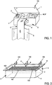
- FIG. 1 the main elements constituting a lifting module 100 according to the invention.
- the latter comprises a drive unit A controlling the immersion movements (in the direction of descent) and lifting of the moving base 3.
- the lifting module 100 also comprises a guide element B of a peripheral zone of the moving base 3
- the lifting module 100 further comprises a transmission element C connected on the one hand to the drive housing A and on the other hand to the moving bottom 3.
- the lifting module 100 acts at a single point of lifting.
- the concept of "lifting point” means a zone restricted to the periphery of the movable floor 3, of the order of a few centimeters or decimetres.
- the transmission element C is therefore connected to the moving bottom 3 at a single lifting point.
- An immersion (or descent) or lifting movement is imparted to the moving bottom 3 by a set of lifting modules 100 which are arranged in as many units as necessary on the edges of the Pool D of the pool.
- the figure 2 illustrates the implantation of six lifting modules 100 acting at six lifting point of the movable base 3.
- the number and distribution of the lifting modules are a function of the load to be supported and driven, which depends directly on the weight of the moving floor 3 but also the shape of the movable bottom 3. It is important to aim for a balanced distribution and the most homogeneous possible efforts to support each of the lifting modules 100.
- the lifting modules 100 of the installation are activated by an adjustment and synchronization device.
- the latter is adapted to control lifting strokes that may be similar or different at each lifting point.
- the various modules 100 can control the displacement of the mobile base 3 while keeping it substantially horizontal regardless of its height.
- the various modules 100 can control the displacement of the mobile base 3 by tilting it to a desired angle, for example so as to fit a bottom of the pool which would itself be inclined with respect to a horizontal plane.
- the drive housing A comprises a motor M, M 'connected to the transmission element C. This connection is provided by drive means (not shown) such as a set of pulleys or accessories or reduction means which are classic and of a design perfectly within the reach of the skilled person.
- the motor M is a motor driven by electrical energy.
- the motor is connected to a standard electrical circuit and complies with the rules in force for the supply of power to outdoor equipment.
- a climbing speed of 0.03 m / s, a pulley radius of 0.05 m at the motor shaft output, a linear acceleration of 1m / s 2 , a yield of 0.6 and a lifting distance of 2.5 m we obtain a necessary mechanical power of the order of 75 W for a nominal torque of 125 Nm.
- four electric motors we divide by four the power necessary for each one.
- the motor M ' is driven by hydraulic energy.
- a hydraulic motor also dispenses to provide braking means capable of blocking the displacement of the movable base 3.
- a hydraulic motor motor pump unit
- Each motor is hydraulically independent and has its own supply of fluid. Only one power supply is to be routed to drive unit A for the pump motor.
- a pump motor suitable for each module may be of the "CASAPPA Polaris 10 series pump” type.
- the developed torque (at 100 bar) is 1.35 Nm.
- the flow rate at 700 rpm is 0.68 l / min.
- the minimum operating speed is 650 rpm which implies the implementation of a reduction ratio of 132.
- the housing 1 constituting the drive housing A is made of a rigid material, strong enough to support the weight of one or two people leaning on it. This material is adapted to resist corrosion, by its chemical composition, or through a surface treatment.
- the drive housing A has on its upper part an access hatch T to install its components, but also to intervene directly in the mechanism for its troubleshooting or adjustment of operation.
- the drive housing A also encloses an indicator 2, preferably a visual indicator, which makes it possible to precisely identify, at the point of the lifting itself, the exact position of the moving base 3 with respect to the bottom 4 of the swimming pool.
- This positioning indicator 2 of the movable bottom 3 facilitates the adjustment and synchronization of the different lifting modules 100 between them.
- the mobile bottom 3 In the high position, called security, the mobile bottom 3 automatically finds and thanks to the settings a perfectly horizontal attitude.
- the guide member B is a rail having the general shape of a profile disposed substantially vertically along a vertical wall delimiting the basin D of the pool.
- the movable base 3 is provided with sliding and / or rolling means 6, typically balls (as illustrated in FIG. figure 6 ) or rollers held at the periphery of the movable bottom 3, cooperating in contact with the guide member B.
- the guide member B has a corrugated section. This section is provided with a central recess accommodating the sliding and / or rolling means 6, this central recess is bordered by lateral bosses channeling the sliding and / or rolling means 6 during their movement along the element. guidance. This corrugated shape is particularly suitable for optimal guidance of the moving floor, while being extremely simple to design and install.
- the guide member B is suspended by its upper end to a mounting plate 7. It is mounted on an upper edge of the pool, typically consisting of a structural element of the pool or a coping E.
- the fixation of the plate 7 on the structure or the lip E may be provided by fixing screws or by bonding or by any equivalent appropriate means.
- the guide element B is connected to the plate 7 by means that can be articulated, for example to allow easy packaging and transport (the platinum-guide element assembly being flat or folded on itself), and for a quick installation on the edge of the pool (the guide element B is positioned at 90 ° relative to the plate 7).
- the inclination at 90 ° between the plate 7 and the guide element B can be blocked by appropriate means, for example by a system of pins.
- the guide element B and the plate 7 can be automatically rigidly fixed at 90 ° to each other.
- the guide element B is devoid of attachment with a vertical wall 5 against which it is attached.
- the guide element B is simply oriented to fit this wall 5.
- the sliding and / or rolling means 6 only have the effect of abutting against the guiding element, which contributes to the plate against the wall 5 of the basin. It is not necessary to provide means for retaining the guide element.
- the guide element is made of stainless material, such as stainless steel.
- the guide element B may comprise on its face facing the wall 5, a coating or a layer 8 made of plastic, rubber or foam ( figure 3 ).
- the transmission element C connected to the engine M, M ' is also connected to the lifting point of the movable base 3 by appropriate attachment means, in order to transmit the traction forces to this lifting point.
- the transmission element C is a "marine" type strap, made of synthetic material, for example plastic or nylon or the like, particularly suitable for use in a chlorinated aquatic environment.
- a strap has extremely high tensile strength characteristics, for a relatively small thickness, which minimizes its bulk in the drive housing A when wound.
- the strap C is provided at each of its ends with an arrangement 13 allowing on the one hand its positioning and its anchoring on one of the internal drive elements to the drive housing A, and secondly its attachment to fastening means for connecting to the movable bottom 3.
- the strap C is provided with one or more inserts 14 intended to limit friction during the path along the guide element B.
- the drive housing A can be implanted in different ways.
- the housing A is mounted externally to an upper edge E of the pool, so that a lower part of the housing A is buried in the ground, set back relative to the basin D.
- the housing A is mounted over an outer edge E of the pool.
- the housing A can thus constitute in itself a stud from which one can dive into the pool.
- the housing A can also be integrated in a stud of this type.
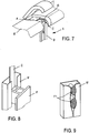
- a return roller 9 may be provided at the junction of the plate 7 and the guide member B, so as to promote the rolling of the transmission element C which is to form a return angle in this area. In the same manner, it is possible to provide a return roller 9 'in other passage zones of the transmission element C, for example near the drive housing A ( figure 1 ).
- the sliding and / or rolling means typically balls in the illustrated example
- the sliding and / or rolling means can be mounted movably in a corresponding housing 10 formed at the periphery of the movable bottom 3, so as to make a clearance clearance between the wall
- the ball is projecting about one-third of its diameter.
- a return spring 11 tends to push the ball towards the peripheral edge of the movable bottom 3.
- the imprisoning means 12 are located at the mouth of the housing 10 so as to prevent the ball from leaving its housing.
- FIG. figure 7 Another alternative embodiment of the drive housing A is also conceivable, as shown in FIG. figure 7 .
- the housing is located in a housing provided under the edge of the pool E.
- This mode of implementation requires a heavier adaptation of an existing pool (compared to the locations of figures 4 and 5 ), to receive the lifting module. It is also possible to provide visual cues on the rim E or nearby, so as to know precisely the location of drive boxes A concealed beneath the lip E.
- a lifting module according to the invention because of its simplicity, and the very principle of autonomy of the module, is perfectly suitable for installation on existing pool basins, the side walls of which are substantially vertical, without requiring any additional cost. equipment, excessive development.
- the transmission element may be a cable (not shown), replacing the strap, without calling into question other features of the invention.
- the rail B ' is attached and fixed to the wall of the basin D, for example by means of fixing screws, by gluing or by clipping means, which make it particularly removable .
- the section of the guide element B ' may have a general shape C, a central portion is contiguous to the wall 5 of the pool D pool.
- the opening of this section C along the entire length of the rail allows the displacement of the fastening means F, which secure the lower end of the transmission element C to the movable bottom 3, along the entire length of the rail .
- the guide element B ' may be entirely made of plastic, flexible or rigid, compatible with the chlorinated aquatic environment. With reference to the figure 9 this element may also comprise edges or lips delimiting the opening of the C, which are relatively flexible, so as to open during the passage of the attachment means F1, and to close by elasticity after their passage. This closing effect offers swimmers a smooth and non-aggressive surface.
- the body of the guide element may be made of a first, relatively rigid material, while the edges or lips of the opening of the C are made of a second, softer material allowing them to spacing and their closure under the solicitation of fastening means F1.
- the guide member B is positioned to be embedded or recessed in the inner wall 5 of the pond D.
- This arrangement provides flush surfaces of the guide member B" relative to the wall 5 of the basin, the guiding element particularly little aggressive for bather. This arrangement however supposes to provide for this integration of the guiding element as soon as the pool D is made.
Landscapes
- Engineering & Computer Science (AREA)
- Architecture (AREA)
- Civil Engineering (AREA)
- Structural Engineering (AREA)
- Devices For Medical Bathing And Washing (AREA)
- Invalid Beds And Related Equipment (AREA)
- Toys (AREA)
Claims (15)
- Hubmodul (100) für beweglichen festen Schwimmbadboden (3), bestehend aus:a) einer Antriebseinheit (A) zur Steuerung der Eintauch- und Hubbewegungen an einem einzelnen Punkt des beweglichen Bodens (3),b) mindestens einem Randführungselement (B, B', B") des beweglichen Bodens (3),c) mindestens einem Kraftübertragungselement (C), verbunden einerseits mit der Antriebseinheit (A) und andererseits mit dem genannten einzelnen Punkt des beweglichen Bodens (3),
wobei das Hubmodul sich durch vollständige Autonomie auszeichnet, in dem Sinne, dass es über keine mechanische Verbindung zu irgendeinem anderen Hebezeug verfügt, das an einem anderen Hebepunkt des beweglichen Bodens (3) ansetzt. - Hubmodul entsprechend Patentanspruch 1, bei dem die Antriebseinheit (A) einen Elektromotor (M) enthält, der so über Antriebsvorrichtungen wie einen Scheibensatz oder Zubehör oder Reduziergetriebe mit dem Kraftübertragungselement (C) verbunden ist, dass der bewegliche Boden (3) im Becken (D) des Schwimmbads eingetaucht oder angehoben wird.
- Hubmodul entsprechend Patentanspruch 1, bei dem die Antriebseinheit (A) einen Hydraulikmotor (M') enthält, der so über Antriebsvorrichtungen wie einen Scheibensatz oder Zubehör mit dem Kraftübertragungselement (C) verbunden ist, dass der bewegliche Boden (3) im Becken (D) des Schwimmbads eingetaucht oder angehoben wird.
- Hubmodul entsprechend einem beliebigen der Patentansprüche 1 bis 3, bei dem das Führungselement (B, B', B") eine Schiene mit der allgemeinen Form eines deutlich vertikal entlang einer senkrechten Wand (5) angebrachten Profils ist, die das Becken (D) vom Schwimmbad trennt, wobei der bewegliche Boden (3) mit Gleit- und/oder Rollvorrichtungen am Rand versehen ist, die sich auf eine Fläche der Schiene abstützen.
- Hubmodul entsprechend Patentanspruch 4, bei dem das Führungselement (B, B', B") am oberen Ende an einer Befestigungsplatte (7) aufgehängt ist, die an einem oberen Rand (E) des Schwimmbads montiert ist, der insbesondere aus einem Strukturelement und bzw. oder einer Brüstung besteht.
- Hubmodul entsprechend Patentanspruch 5, bei dem das Führungselement (B) über keine Befestigung an der senkrechten Wand (5) verfügt, an der es angebracht ist.
- Hubmodul entsprechend einem beliebigen der Patentansprüche 4 bis 6, bei dem das Führungselement (B) aus nicht rostendem Material besteht und mit einem Schaumstoffbelag (8) an einer Fläche gegenüber der senkrechten Wand (5) versehen ist, so dass ein schonender Kontakt mit letzterer gewährleistet ist.
- Hubmodul entsprechend einem beliebigen der Patentansprüche 4 bis 7, bei dem der Querschnitt des Führungselements (B) eine gewellte Form aufweist mit zentraler Verstärkung, die mit den Gleit- und oder Rollvorrichtungen (6) des beweglichen Bodens (3) zusammenwirkt, wobei die Verstärkung mit seitlichen Buckeln versehen ist, die die Führung des beweglichen Bodens (3) in der Verstärkung gewährleisten.
- Hubmodul entsprechend einem beliebigen der Patentansprüche 1 bis 8, bei dem das Kraftübertragungselement (C) aus einem Band in Marine-Ausführung besteht.
- Hubmodul entsprechend einem beliebigen der Patentansprüche 1 bis 9, bei dem eine Leitrolle (9) am oberen Teil des Führungselements (B, B', B") und bzw. oder an der Befestigungsplatte (7) angebracht ist, wobei das Kraftübertragungselement (C) die Antriebseinheit (A) mit dem Hebepunkt auf dieser Leitrolle (9) verbindet.
- Hubanlage für beweglichen festen Schwimmbadboden (3), die mehrere Hubmodule (100) entsprechend einem beliebigen der Patentansprüche 1 bis 10 umfasst, die an mehreren Hebepunkten des beweglichen Bodens (3) ansetzen, die über dessen Rand verteilt sind.
- Hubanlage entsprechend Patentanspruch 11, die über eine Regel- und Synchronisationseinrichtung für den Betrieb der verschiedenen Hubmodule (100) verfügt.
- Hubanlage entsprechend Patentanspruch 12, bei dem die Regel- und Synchronisationseinrichtung verschiedene Hub- oder Eintauchwege für die unterschiedlichen Hebepunkte des beweglichen Bodens (3) erzeugen können, so dass sich letzterer unabhängig vom Neigungswinkel des Unterbaus (4) des Schwimmbadbeckens (D) auf den Boden (4) des Schwimmbads drücken lässt.
- Schwimmbad mit beweglichem festem Boden (3), das über eine Hubanlage für den beweglichen Boden (3) entsprechend einem beliebigen der Patentansprüche 11 bis 13 verfügt, wobei das Schwimmbad auch mit mindestens einer Antriebseinheit (A) ausgestattet ist, die an einem oberen Rand (E) des Schwimmbads montiert ist, etwa an einem Strukturelement und bzw. oder einer Brüstung, und über diesen oberen Rand (E) hinausragt.
- Schwimmbad mit beweglichem festem Boden (3), das über eine Hubanlage für den beweglichen Boden (3) entsprechend einem beliebigen der Patentansprüche 11 bis 13 verfügt, wobei das Schwimmbad auch mit mindestens einer Antriebseinheit (A) ausgestattet ist, die extern an einem oberen Rand (E) des Schwimmbads montiert ist, so dass mindestens ein Teil der Antriebseinheit (A) in den Boden eingelassen ist, der mit diesem Rand (E) bündig abschließt.
Applications Claiming Priority (2)
| Application Number | Priority Date | Filing Date | Title |
|---|---|---|---|
| FR0706176A FR2920455A1 (fr) | 2007-09-04 | 2007-09-04 | Module autonome de levage pour fond mobile de piscine. |
| PCT/FR2008/051569 WO2009044039A2 (fr) | 2007-09-04 | 2008-09-03 | Module autonome de levage pour fond mobile de piscine |
Publications (2)
| Publication Number | Publication Date |
|---|---|
| EP2205809A2 EP2205809A2 (de) | 2010-07-14 |
| EP2205809B1 true EP2205809B1 (de) | 2012-04-25 |
Family
ID=39491541
Family Applications (1)
| Application Number | Title | Priority Date | Filing Date |
|---|---|---|---|
| EP08835415A Not-in-force EP2205809B1 (de) | 2007-09-04 | 2008-09-03 | Autonome hebevorrichtung für den beweglichen boden eines schwimmbeckens |
Country Status (5)
| Country | Link |
|---|---|
| US (1) | US20100199416A1 (de) |
| EP (1) | EP2205809B1 (de) |
| AT (1) | ATE555265T1 (de) |
| FR (1) | FR2920455A1 (de) |
| WO (1) | WO2009044039A2 (de) |
Families Citing this family (4)
| Publication number | Priority date | Publication date | Assignee | Title |
|---|---|---|---|---|
| FR2958310B1 (fr) * | 2010-04-06 | 2012-12-28 | Amin Hassan Mamode | Dispositif de fermeture de bassin de piscine par plancher rigide immergeable suspendu et verrouillable. |
| EP2792815B1 (de) | 2013-04-19 | 2015-12-30 | Amphibia | Vorrichtung zum Bewegen einer mobilen Plattform, insbesondere für ein Schwimmbad |
| US10794073B2 (en) * | 2018-11-15 | 2020-10-06 | Universal City Studios Llc | Systems and methods for an entertainment system |
| US20220315318A1 (en) | 2019-06-03 | 2022-10-06 | Luciana Christina MANFRINATO CAMBRIA | Extendable container for fluids with variable containment volume and dimensions |
Family Cites Families (5)
| Publication number | Priority date | Publication date | Assignee | Title |
|---|---|---|---|---|
| DE1914286A1 (de) * | 1969-03-20 | 1970-10-01 | Keller Dipl Ing J G Stefan | Zwischenbodenvorrichtung fuer Schwimmbecken |
| DE8812985U1 (de) * | 1988-10-15 | 1988-12-01 | Bertsch, Erich, 7850 Loerrach, De | |
| US5542502A (en) * | 1995-05-02 | 1996-08-06 | Scriven; Reginald K. | Hoist driven rescue mat for swimming pool |
| US6389615B2 (en) * | 2000-06-02 | 2002-05-21 | Gregory Perrier | Fail-safe safety swimming pool net |
| DE102006003504A1 (de) * | 2006-01-24 | 2007-08-02 | Stelzer, Rolf | Vorrichtung zum vertikalen Bewegen einer horizontalen Abdeckplatte |
-
2007
- 2007-09-04 FR FR0706176A patent/FR2920455A1/fr not_active Withdrawn
-
2008
- 2008-09-03 AT AT08835415T patent/ATE555265T1/de active
- 2008-09-03 WO PCT/FR2008/051569 patent/WO2009044039A2/fr active Application Filing
- 2008-09-03 EP EP08835415A patent/EP2205809B1/de not_active Not-in-force
- 2008-09-03 US US12/676,105 patent/US20100199416A1/en not_active Abandoned
Also Published As
| Publication number | Publication date |
|---|---|
| EP2205809A2 (de) | 2010-07-14 |
| US20100199416A1 (en) | 2010-08-12 |
| WO2009044039A3 (fr) | 2009-05-28 |
| WO2009044039A2 (fr) | 2009-04-09 |
| FR2920455A1 (fr) | 2009-03-06 |
| ATE555265T1 (de) | 2012-05-15 |
Similar Documents
| Publication | Publication Date | Title |
|---|---|---|
| EP2771525B1 (de) | Vorrichtung zur reinigung einer unterwasserfläche mit halbautomatischem wendebefehl | |
| EP2205809B1 (de) | Autonome hebevorrichtung für den beweglichen boden eines schwimmbeckens | |
| EP1434916A1 (de) | Zwischen zwei positionen, eine auf dem boden aufliegende und eine schwimmende, bewegliche gebäudeanordnung | |
| FR2981380A1 (fr) | Piscine a plancher mobile | |
| WO2018087498A1 (fr) | Piscine a fond mobile et a debordement | |
| EP1741854B1 (de) | Schützvorrichtung für eine schwimende Schwimmbadabdeckung | |
| FR2928394A1 (fr) | Dispositif de guidage combine pour abri telescopique | |
| FR3050474A1 (fr) | Dispositif d'acces a un bassin d'une piscine | |
| WO1995010678A1 (fr) | Dispositif d'adaptation d'une couverture flottante enroulable sur une piscine | |
| FR2958310A1 (fr) | Dispositif de fermeture de bassin de piscine par plancher rigide immergeable suspendu et verrouillable. | |
| FR3058992B1 (fr) | Systeme de montee/descente d’une structure submersible au sein d’un volume d’eau, notamment pour un plancher de piscine mobile | |
| EP3283710B1 (de) | Schwimmende struktur | |
| EP2960399B1 (de) | Antriebsvorrichtung für aufrollbare Schwimmbadabdeckung, und damit ausgestattetes Schwimmbad | |
| FR3124535A1 (fr) | Support pour couverture immergée de piscine | |
| EP1699994B1 (de) | Wartungsvorrichtung für die wand eines gebäudes mit einer röhrenförmigen befestigungsstruktur | |
| FR2840003A1 (fr) | Dispositif enrouleur pour couverture pour piscine | |
| FR2957106A1 (fr) | Equipement de securite pour piscine | |
| FR2942636A1 (fr) | Plancher mobile de piscine | |
| FR2967184A1 (fr) | Kit d'habillage pour un systeme d'enroulement d'une couverture de piscine | |
| FR2981381A1 (fr) | Dispositif pour l'installation d'un fond mobile dans un bassin et fond mobile pour un tel bassin | |
| EP1849933A1 (de) | Verkleidungsstruktur für eine nicht am Boden verlaufende Auf-/ Abrollvorrichtung eines Schwimmbadrollladens und Schwimmbad mit dieser Struktur | |
| EP4148205A1 (de) | Automatische abdeckung eines schwimmbeckens | |
| FR2500519A1 (fr) | Piscine de type flottant et procede de realisation | |
| FR3095466A1 (fr) | Abri motorisé pour bassin d’agrément | |
| FR2668526A1 (fr) | Bassin formant piscine dispose a l'interieur d'un local d'habitation. |
Legal Events
| Date | Code | Title | Description |
|---|---|---|---|
| PUAI | Public reference made under article 153(3) epc to a published international application that has entered the european phase |
Free format text: ORIGINAL CODE: 0009012 |
|
| 17P | Request for examination filed |
Effective date: 20100331 |
|
| AK | Designated contracting states |
Kind code of ref document: A2 Designated state(s): AT BE BG CH CY CZ DE DK EE ES FI FR GB GR HR HU IE IS IT LI LT LU LV MC MT NL NO PL PT RO SE SI SK TR |
|
| AX | Request for extension of the european patent |
Extension state: AL BA MK RS |
|
| GRAP | Despatch of communication of intention to grant a patent |
Free format text: ORIGINAL CODE: EPIDOSNIGR1 |
|
| DAX | Request for extension of the european patent (deleted) | ||
| GRAS | Grant fee paid |
Free format text: ORIGINAL CODE: EPIDOSNIGR3 |
|
| GRAA | (expected) grant |
Free format text: ORIGINAL CODE: 0009210 |
|
| AK | Designated contracting states |
Kind code of ref document: B1 Designated state(s): AT BE BG CH CY CZ DE DK EE ES FI FR GB GR HR HU IE IS IT LI LT LU LV MC MT NL NO PL PT RO SE SI SK TR |
|
| REG | Reference to a national code |
Ref country code: GB Ref legal event code: FG4D Free format text: NOT ENGLISH |
|
| REG | Reference to a national code |
Ref country code: CH Ref legal event code: EP |
|
| REG | Reference to a national code |
Ref country code: AT Ref legal event code: REF Ref document number: 555265 Country of ref document: AT Kind code of ref document: T Effective date: 20120515 |
|
| REG | Reference to a national code |
Ref country code: IE Ref legal event code: FG4D Free format text: LANGUAGE OF EP DOCUMENT: FRENCH |
|
| REG | Reference to a national code |
Ref country code: DE Ref legal event code: R096 Ref document number: 602008015250 Country of ref document: DE Effective date: 20120621 |
|
| REG | Reference to a national code |
Ref country code: NL Ref legal event code: VDEP Effective date: 20120425 |
|
| REG | Reference to a national code |
Ref country code: AT Ref legal event code: MK05 Ref document number: 555265 Country of ref document: AT Kind code of ref document: T Effective date: 20120425 |
|
| LTIE | Lt: invalidation of european patent or patent extension |
Effective date: 20120425 |
|
| PG25 | Lapsed in a contracting state [announced via postgrant information from national office to epo] |
Ref country code: CY Free format text: LAPSE BECAUSE OF FAILURE TO SUBMIT A TRANSLATION OF THE DESCRIPTION OR TO PAY THE FEE WITHIN THE PRESCRIBED TIME-LIMIT Effective date: 20120425 Ref country code: IS Free format text: LAPSE BECAUSE OF FAILURE TO SUBMIT A TRANSLATION OF THE DESCRIPTION OR TO PAY THE FEE WITHIN THE PRESCRIBED TIME-LIMIT Effective date: 20120825 Ref country code: SE Free format text: LAPSE BECAUSE OF FAILURE TO SUBMIT A TRANSLATION OF THE DESCRIPTION OR TO PAY THE FEE WITHIN THE PRESCRIBED TIME-LIMIT Effective date: 20120425 Ref country code: LT Free format text: LAPSE BECAUSE OF FAILURE TO SUBMIT A TRANSLATION OF THE DESCRIPTION OR TO PAY THE FEE WITHIN THE PRESCRIBED TIME-LIMIT Effective date: 20120425 Ref country code: NO Free format text: LAPSE BECAUSE OF FAILURE TO SUBMIT A TRANSLATION OF THE DESCRIPTION OR TO PAY THE FEE WITHIN THE PRESCRIBED TIME-LIMIT Effective date: 20120725 Ref country code: PL Free format text: LAPSE BECAUSE OF FAILURE TO SUBMIT A TRANSLATION OF THE DESCRIPTION OR TO PAY THE FEE WITHIN THE PRESCRIBED TIME-LIMIT Effective date: 20120425 Ref country code: FI Free format text: LAPSE BECAUSE OF FAILURE TO SUBMIT A TRANSLATION OF THE DESCRIPTION OR TO PAY THE FEE WITHIN THE PRESCRIBED TIME-LIMIT Effective date: 20120425 |
|
| PG25 | Lapsed in a contracting state [announced via postgrant information from national office to epo] |
Ref country code: LV Free format text: LAPSE BECAUSE OF FAILURE TO SUBMIT A TRANSLATION OF THE DESCRIPTION OR TO PAY THE FEE WITHIN THE PRESCRIBED TIME-LIMIT Effective date: 20120425 Ref country code: GR Free format text: LAPSE BECAUSE OF FAILURE TO SUBMIT A TRANSLATION OF THE DESCRIPTION OR TO PAY THE FEE WITHIN THE PRESCRIBED TIME-LIMIT Effective date: 20120726 Ref country code: PT Free format text: LAPSE BECAUSE OF FAILURE TO SUBMIT A TRANSLATION OF THE DESCRIPTION OR TO PAY THE FEE WITHIN THE PRESCRIBED TIME-LIMIT Effective date: 20120827 Ref country code: SI Free format text: LAPSE BECAUSE OF FAILURE TO SUBMIT A TRANSLATION OF THE DESCRIPTION OR TO PAY THE FEE WITHIN THE PRESCRIBED TIME-LIMIT Effective date: 20120425 Ref country code: HR Free format text: LAPSE BECAUSE OF FAILURE TO SUBMIT A TRANSLATION OF THE DESCRIPTION OR TO PAY THE FEE WITHIN THE PRESCRIBED TIME-LIMIT Effective date: 20120425 |
|
| PG25 | Lapsed in a contracting state [announced via postgrant information from national office to epo] |
Ref country code: DK Free format text: LAPSE BECAUSE OF FAILURE TO SUBMIT A TRANSLATION OF THE DESCRIPTION OR TO PAY THE FEE WITHIN THE PRESCRIBED TIME-LIMIT Effective date: 20120425 Ref country code: SK Free format text: LAPSE BECAUSE OF FAILURE TO SUBMIT A TRANSLATION OF THE DESCRIPTION OR TO PAY THE FEE WITHIN THE PRESCRIBED TIME-LIMIT Effective date: 20120425 Ref country code: CZ Free format text: LAPSE BECAUSE OF FAILURE TO SUBMIT A TRANSLATION OF THE DESCRIPTION OR TO PAY THE FEE WITHIN THE PRESCRIBED TIME-LIMIT Effective date: 20120425 Ref country code: RO Free format text: LAPSE BECAUSE OF FAILURE TO SUBMIT A TRANSLATION OF THE DESCRIPTION OR TO PAY THE FEE WITHIN THE PRESCRIBED TIME-LIMIT Effective date: 20120425 Ref country code: EE Free format text: LAPSE BECAUSE OF FAILURE TO SUBMIT A TRANSLATION OF THE DESCRIPTION OR TO PAY THE FEE WITHIN THE PRESCRIBED TIME-LIMIT Effective date: 20120425 Ref country code: AT Free format text: LAPSE BECAUSE OF FAILURE TO SUBMIT A TRANSLATION OF THE DESCRIPTION OR TO PAY THE FEE WITHIN THE PRESCRIBED TIME-LIMIT Effective date: 20120425 Ref country code: NL Free format text: LAPSE BECAUSE OF FAILURE TO SUBMIT A TRANSLATION OF THE DESCRIPTION OR TO PAY THE FEE WITHIN THE PRESCRIBED TIME-LIMIT Effective date: 20120425 |
|
| PG25 | Lapsed in a contracting state [announced via postgrant information from national office to epo] |
Ref country code: IT Free format text: LAPSE BECAUSE OF FAILURE TO SUBMIT A TRANSLATION OF THE DESCRIPTION OR TO PAY THE FEE WITHIN THE PRESCRIBED TIME-LIMIT Effective date: 20120425 |
|
| PLBE | No opposition filed within time limit |
Free format text: ORIGINAL CODE: 0009261 |
|
| STAA | Information on the status of an ep patent application or granted ep patent |
Free format text: STATUS: NO OPPOSITION FILED WITHIN TIME LIMIT |
|
| BERE | Be: lapsed |
Owner name: AD PISCINES (SOCIETE A RESPONSABILITE LIMITEE) Effective date: 20120930 |
|
| 26N | No opposition filed |
Effective date: 20130128 |
|
| REG | Reference to a national code |
Ref country code: DE Ref legal event code: R119 Ref document number: 602008015250 Country of ref document: DE |
|
| PG25 | Lapsed in a contracting state [announced via postgrant information from national office to epo] |
Ref country code: MC Free format text: LAPSE BECAUSE OF NON-PAYMENT OF DUE FEES Effective date: 20120930 Ref country code: ES Free format text: LAPSE BECAUSE OF FAILURE TO SUBMIT A TRANSLATION OF THE DESCRIPTION OR TO PAY THE FEE WITHIN THE PRESCRIBED TIME-LIMIT Effective date: 20120805 |
|
| REG | Reference to a national code |
Ref country code: CH Ref legal event code: PL |
|
| GBPC | Gb: european patent ceased through non-payment of renewal fee |
Effective date: 20120903 |
|
| REG | Reference to a national code |
Ref country code: DE Ref legal event code: R097 Ref document number: 602008015250 Country of ref document: DE Effective date: 20130128 |
|
| REG | Reference to a national code |
Ref country code: IE Ref legal event code: MM4A |
|
| REG | Reference to a national code |
Ref country code: FR Ref legal event code: ST Effective date: 20130531 |
|
| PG25 | Lapsed in a contracting state [announced via postgrant information from national office to epo] |
Ref country code: DE Free format text: LAPSE BECAUSE OF NON-PAYMENT OF DUE FEES Effective date: 20130403 Ref country code: LI Free format text: LAPSE BECAUSE OF NON-PAYMENT OF DUE FEES Effective date: 20120930 Ref country code: BG Free format text: LAPSE BECAUSE OF FAILURE TO SUBMIT A TRANSLATION OF THE DESCRIPTION OR TO PAY THE FEE WITHIN THE PRESCRIBED TIME-LIMIT Effective date: 20120725 Ref country code: BE Free format text: LAPSE BECAUSE OF NON-PAYMENT OF DUE FEES Effective date: 20120930 Ref country code: IE Free format text: LAPSE BECAUSE OF NON-PAYMENT OF DUE FEES Effective date: 20120903 Ref country code: GB Free format text: LAPSE BECAUSE OF NON-PAYMENT OF DUE FEES Effective date: 20120903 Ref country code: CH Free format text: LAPSE BECAUSE OF NON-PAYMENT OF DUE FEES Effective date: 20120930 |
|
| PG25 | Lapsed in a contracting state [announced via postgrant information from national office to epo] |
Ref country code: FR Free format text: LAPSE BECAUSE OF NON-PAYMENT OF DUE FEES Effective date: 20121001 |
|
| REG | Reference to a national code |
Ref country code: DE Ref legal event code: R119 Ref document number: 602008015250 Country of ref document: DE Effective date: 20130403 |
|
| PG25 | Lapsed in a contracting state [announced via postgrant information from national office to epo] |
Ref country code: MT Free format text: LAPSE BECAUSE OF FAILURE TO SUBMIT A TRANSLATION OF THE DESCRIPTION OR TO PAY THE FEE WITHIN THE PRESCRIBED TIME-LIMIT Effective date: 20120425 |
|
| PG25 | Lapsed in a contracting state [announced via postgrant information from national office to epo] |
Ref country code: TR Free format text: LAPSE BECAUSE OF FAILURE TO SUBMIT A TRANSLATION OF THE DESCRIPTION OR TO PAY THE FEE WITHIN THE PRESCRIBED TIME-LIMIT Effective date: 20120425 |
|
| PG25 | Lapsed in a contracting state [announced via postgrant information from national office to epo] |
Ref country code: LU Free format text: LAPSE BECAUSE OF NON-PAYMENT OF DUE FEES Effective date: 20120903 |
|
| PG25 | Lapsed in a contracting state [announced via postgrant information from national office to epo] |
Ref country code: HU Free format text: LAPSE BECAUSE OF FAILURE TO SUBMIT A TRANSLATION OF THE DESCRIPTION OR TO PAY THE FEE WITHIN THE PRESCRIBED TIME-LIMIT Effective date: 20080903 |