EP2205365B1 - Continual flow pin washer - Google Patents
Continual flow pin washer Download PDFInfo
- Publication number
- EP2205365B1 EP2205365B1 EP08839397.0A EP08839397A EP2205365B1 EP 2205365 B1 EP2205365 B1 EP 2205365B1 EP 08839397 A EP08839397 A EP 08839397A EP 2205365 B1 EP2205365 B1 EP 2205365B1
- Authority
- EP
- European Patent Office
- Prior art keywords
- tube
- cleaning
- fluid
- pin
- pins
- Prior art date
- Legal status (The legal status is an assumption and is not a legal conclusion. Google has not performed a legal analysis and makes no representation as to the accuracy of the status listed.)
- Not-in-force
Links
- 239000012530 fluid Substances 0.000 claims description 140
- 238000004140 cleaning Methods 0.000 claims description 132
- 238000000151 deposition Methods 0.000 claims description 44
- 230000008021 deposition Effects 0.000 claims description 44
- 238000000034 method Methods 0.000 claims description 20
- 238000004891 communication Methods 0.000 claims description 18
- 238000007639 printing Methods 0.000 claims description 12
- 238000011282 treatment Methods 0.000 claims description 7
- 239000000463 material Substances 0.000 claims description 6
- 239000007921 spray Substances 0.000 claims description 6
- 238000005422 blasting Methods 0.000 claims description 4
- 238000005234 chemical deposition Methods 0.000 claims description 3
- 239000011324 bead Substances 0.000 claims description 2
- 230000002209 hydrophobic effect Effects 0.000 claims description 2
- 238000004381 surface treatment Methods 0.000 claims 2
- 239000002699 waste material Substances 0.000 description 11
- 238000005406 washing Methods 0.000 description 7
- 239000007787 solid Substances 0.000 description 5
- 238000013019 agitation Methods 0.000 description 2
- 238000011109 contamination Methods 0.000 description 2
- 238000012864 cross contamination Methods 0.000 description 2
- 239000007788 liquid Substances 0.000 description 2
- 238000002493 microarray Methods 0.000 description 2
- 238000002156 mixing Methods 0.000 description 2
- 238000000527 sonication Methods 0.000 description 2
- 239000000126 substance Substances 0.000 description 2
- 238000012546 transfer Methods 0.000 description 2
- 230000009471 action Effects 0.000 description 1
- 238000003491 array Methods 0.000 description 1
- 239000010789 controlled waste Substances 0.000 description 1
- 230000008878 coupling Effects 0.000 description 1
- 238000010168 coupling process Methods 0.000 description 1
- 238000005859 coupling reaction Methods 0.000 description 1
- 238000013461 design Methods 0.000 description 1
- 230000001627 detrimental effect Effects 0.000 description 1
- 238000000605 extraction Methods 0.000 description 1
- 230000005484 gravity Effects 0.000 description 1
- 230000001788 irregular Effects 0.000 description 1
- 230000007246 mechanism Effects 0.000 description 1
- 238000012986 modification Methods 0.000 description 1
- 230000004048 modification Effects 0.000 description 1
- 230000008569 process Effects 0.000 description 1
- 238000005086 pumping Methods 0.000 description 1
- 230000003134 recirculating effect Effects 0.000 description 1
- 230000000630 rising effect Effects 0.000 description 1
- 238000005507 spraying Methods 0.000 description 1
- 238000003860 storage Methods 0.000 description 1
- 230000001052 transient effect Effects 0.000 description 1
- 239000002351 wastewater Substances 0.000 description 1
Images


Classifications
-
- B—PERFORMING OPERATIONS; TRANSPORTING
- B08—CLEANING
- B08B—CLEANING IN GENERAL; PREVENTION OF FOULING IN GENERAL
- B08B3/00—Cleaning by methods involving the use or presence of liquid or steam
- B08B3/04—Cleaning involving contact with liquid
-
- B—PERFORMING OPERATIONS; TRANSPORTING
- B01—PHYSICAL OR CHEMICAL PROCESSES OR APPARATUS IN GENERAL
- B01L—CHEMICAL OR PHYSICAL LABORATORY APPARATUS FOR GENERAL USE
- B01L13/00—Cleaning or rinsing apparatus
- B01L13/02—Cleaning or rinsing apparatus for receptacle or instruments
-
- B—PERFORMING OPERATIONS; TRANSPORTING
- B41—PRINTING; LINING MACHINES; TYPEWRITERS; STAMPS
- B41J—TYPEWRITERS; SELECTIVE PRINTING MECHANISMS, i.e. MECHANISMS PRINTING OTHERWISE THAN FROM A FORME; CORRECTION OF TYPOGRAPHICAL ERRORS
- B41J29/00—Details of, or accessories for, typewriters or selective printing mechanisms not otherwise provided for
- B41J29/17—Cleaning arrangements
-
- G—PHYSICS
- G01—MEASURING; TESTING
- G01N—INVESTIGATING OR ANALYSING MATERIALS BY DETERMINING THEIR CHEMICAL OR PHYSICAL PROPERTIES
- G01N35/00—Automatic analysis not limited to methods or materials provided for in any single one of groups G01N1/00 - G01N33/00; Handling materials therefor
- G01N35/10—Devices for transferring samples or any liquids to, in, or from, the analysis apparatus, e.g. suction devices, injection devices
- G01N35/1004—Cleaning sample transfer devices
-
- B—PERFORMING OPERATIONS; TRANSPORTING
- B01—PHYSICAL OR CHEMICAL PROCESSES OR APPARATUS IN GENERAL
- B01L—CHEMICAL OR PHYSICAL LABORATORY APPARATUS FOR GENERAL USE
- B01L3/00—Containers or dishes for laboratory use, e.g. laboratory glassware; Droppers
- B01L3/02—Burettes; Pipettes
- B01L3/0241—Drop counters; Drop formers
- B01L3/0244—Drop counters; Drop formers using pins
-
- G—PHYSICS
- G01—MEASURING; TESTING
- G01N—INVESTIGATING OR ANALYSING MATERIALS BY DETERMINING THEIR CHEMICAL OR PHYSICAL PROPERTIES
- G01N35/00—Automatic analysis not limited to methods or materials provided for in any single one of groups G01N1/00 - G01N33/00; Handling materials therefor
- G01N35/10—Devices for transferring samples or any liquids to, in, or from, the analysis apparatus, e.g. suction devices, injection devices
- G01N2035/1027—General features of the devices
- G01N2035/1034—Transferring microquantities of liquid
- G01N2035/1037—Using surface tension, e.g. pins or wires
Definitions
- the inventions relate to cleaning deposition pins, and, more specifically, cleaning deposition pins while minimizing cross-contamination between the pins and minimizing the volume of cleaning fluid required.
- Washing of deposition pins can be achieved through several mechanisms. All pins being used could be lowered into a bath of cleaning solution and agitated, either by agitation of the fluid or by motion of the pins themselves. Agitation could be implemented by creating a moving fluid flow, a recirculating fluid flow, or sonication.
- High frequency coupling of energy (sonication, ultrasonics, megasonics, etc.) to aid the cleaning process can be implemented, but adds cost and complexity to implement the drive elements and proper mechanical design to couple the energy on all of the targeted surfaces to be cleaned.
- US6475444 is directed to a rinsing tray system for pipette tips or transfer needles within rinsing liquid that can drain out via an outlet through the force of gravity or that can be removed by pumping out.
- a pin wash station includes a lower chamber, a drain basin, a plurality of cleaning tubes, and a vent tube.
- Each cleaning tube has an inlet end and an outlet end.
- Each tube inlet end is in fluid communication with the lower chamber. The terminus of all tube inlet ends are below a substantially horizontal reference plane.
- Each tube outlet end is in fluid communication with the drain basin such that fluid that exits the outlet end of the tube passes into the drain basin.
- Each tube outlet end is adapted to receive at least a portion of a deposition pin.
- the vent tube has an inlet end and an outlet end. The inlet end is in fluid communication with the lower chamber. The terminus of the vent tube inlet end is above the level of the cleaning tube inlet ends relative to the substantially horizontal reference plane. The outlet end is in fluid communication with the drain basin.
- a system includes a plurality of pins adapted to deposit an array of material dots on a receiving surface and a pin wash station.
- the pin wash station includes a lower chamber, a drain basin, a plurality of cleaning tubes, and a vent tube.
- Each cleaning tube has an inlet end and an outlet end. Each tube inlet end is in fluid communication with the lower chamber. The terminus of all tube inlet ends is below a substantially horizontal reference plane. Each tube outlet end is in fluid communication with the drain basin. Each tube outlet end is adapted to receive one of the plurality of pins.
- the vent tube has an inlet end and an outlet end. The inlet end is in fluid communication with the lower chamber. The terminus of the vent tube inlet end is above the level of the cleaning tube inlet ends relative to the substantially horizontal reference plane. The outlet end is in fluid communication with the drain basin.
- a method of cleaning a plurality of deposition pins in a cleaning system includes a lower chamber, a drain basin, and a plurality of cleaning tubes.
- Each cleaning tube has an inlet end and an outlet end.
- Each tube inlet end is in fluid communication with the lower chamber.
- Each tube outlet end is in fluid communication with the drain basin.
- Each tube outlet end is adapted to receive at least a portion of one of the deposition pins.
- the method includes providing a cleaning fluid into the lower chamber to a level above the outlet ends of each cleaning tube so that vapor within the lower chamber is displaced by the cleaning fluid. Cleaning fluid is provided past this point so that vapor remaining in the lower chamber is compressed and the cleaning fluid flows upward through the cleaning tubes.
- the method also includes disposing at least a portion of a single one of the deposition pins in the tube outlet end of one of the cleaning tubes while the cleaning fluid flows through the cleaning tubes so that the pin is washed within the tube.
- the tube outlet ends are arranged in rows and the method further includes disposing a first row of deposition pins in a row of tube outlet ends; each tube outlet end of the row receiving no more than one deposition pin of the first row of deposition pins.
- the method also includes removing the first row of deposition pins from the row of tube outlet ends and, subsequent to removing the first row of deposition pins from the row of tube outlet ends, disposing a second row of deposition pins in the row of tube outlet ends. Each tube outlet end of the row receives no more than one deposition pin of the second row of deposition pins.
- a plurality of pins are disposed in a plurality of tubes on a one-for-one basis.
- the tube outlet ends are above a level of cleaning fluid such that each of the plurality of pins is washed within a respective cleaning tube.
- the cleaning fluid passes each tube and exits at outlet ends such that the fluid that cleans a first pin is drained and does not come into fluid contact with a second pin.
- Embodiments of the inventions include methods of and systems for cleaning deposition pins.
- Deposition pins are used to deposit small quantities of fluid, semi-fluid, or solid samples of biological or chemical materials. They are usually arranged in an array. Typically, it is a regular two-dimensional rectangular array (e.g., a 48 pin array is typically a 4 x 12 arrangement of pins), but an array could be one-dimensional, have an irregular pattern, or be a single pin.
- Deposition pins are relatively small, and can be approximately 43 - 50 mm in overall length, have an extraction depth of 10 - 16 mm, a diameter ranging between 3.2 - 1.9 mm along the length of the pin, and a tip diameter between 85 - 355 ⁇ m
- deposition pins can have dimensions that are larger or smaller than these dimensions and still be used with embodiments of the inventions.
- Embodiments of the inventions can be used with automated microarray printing systems, such as the one disclosed in U.S. Patent No. 7585463 , entitled “Apparatus and Method For Dispensing Fluid, Semi-Solid and Solid Samples", filed October 25, 2004. This patent describes a printing system that uses a printing head with multiple pins. However, as stated above, embodiments of the inventions can also be used to clean a single pin.
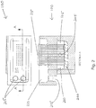
- Fig. 11 is an overview of a pin washing system 1000.
- the washing system 1000 has a deposition pin array 1005 mounted on a pin array conveyor 1010.
- the pin array conveyor 1010 moves the pin array 1005 in the vertical direction.
- the washing system 1000 also includes a multi-chambered wash station 1015 mounted on a wash station conveyor 1020.
- the wash station 1015 is connected to a cleaning fluid reservoir 1025 via a fluid pump 1030 and to a drain by flow control valve 1035.
- the fluid pump 1030 and valve 1035 are controlled by a controller 1040.
- the controller 1040 controls the position of the pin array 1005 on the pin array conveyor 1010 and the position of the wash station 1015 on the wash station conveyor 1020.
- the wash station conveyor 1020 moves the wash station 1015 in the horizontal plane to a position beneath the pin array 1005 that is to be washed. In other embodiments, the wash station 1015 remains in a fixed position.
- the pin array 1005 is lowered via the pin array conveyor 1010 such that the tips of the pins are washed in the wash station 1015, as described in greater detail below.
- the wash station 1015 can be connected to other conveyors to allow the pin array 1005 to remain motionless, while the wash station 1015 is moved as required to wash the pins of the pin array 1005.
- the pin array 1005 can be connected to other conveyors to allow the wash station 1015 to remain motionless, while the pin array 1005 is moved as required to wash the pins of the pin array 1005.
- the controller 1040 controls the fluid pump 1030 and valve 1035 remains closed to provide an appropriate flow of cleaning fluid to the wash station 1015. After one or more wash cycles are complete, valve 1035 is opened to drain any remaining cleaning fluid from the wash station 1015.
- the waste wash fluid exits the wash station 1015 through a drainage tube 1045.
- the drainage tube 1045 can convey used wash fluid to a reservoir or into a waste water system.
- the cleaning fluid reservoir 1025 can be an internal reservoir, an external reservoir, or can be connected to a continuous source of cleaning fluid.
- Fig. 1 is a top view and a cross-sectional side view of a multi-chambered wash station 100 for cleaning a two-dimensional array of deposition pins. While this embodiment is described as useful for cleaning an array of multiple pins, this embodiment, and others, may be used with a printing head having a single deposition pin.
- the multi-chambered wash station 100 has a lower chamber 105 and an upper drain basin 110, which are connected by one or more cleaning tubes 115.
- the cleaning tubes 115 are the primary fluid path between the two chambers.
- tubes 115 are arranged in multiple aligned rows (e.g., four rows of twelve tubes) to match a configuration of multiple pins in a printing array (not shown).
- machined features can be provided in the upper and lower chambers.
- the lower chamber 105 is sealed to the drain basin 110 by one or more of a variety of known techniques around the mated surfaces of the lower chamber 105 and the drain basin 110.
- the tubes are sealed in the drain basin 110 such that the only path for air or liquid to pass from the lower chamber 105 to the drain basin 110 is through the tubes 115.
- Fig. 2 is a top view and a cross-sectional side view of the multi-chambered wash station 100 of Fig. 1 with cleaning fluid 200 in the lower chamber 105.
- Cleaning fluid 200 is pumped into the lower chamber 105 through cleaning fluid inlet 205 so that the fluid level rises and air 210 is displaced and pushed through the tubes 115.
- the fluid level 200 rises until it covers the bottom opening of the highest tube, measured relative to a reference plane that is parallel to the fluid level (e.g., the reference plane can be the substantially horizontal level of the fluid). Once the fluid level 200 reaches the highest tube, the air 210 no longer has a path to the upper drain basin 110.
- the rising fluid level 200 compresses the air 210 trapped at the top of the lower chamber 105 and a counter pressure is applied to the surface of the fluid 200 in the lower chamber 105.
- the pressure on the surface of the fluid 200 acts to push the fluid up each of the tubes 115.
- the flow of cleaning fluid 200 from the lower chamber 105 up the tubes 115 and into the drain basin 110 provides individual fountains for individual pins to be washed. One pin sits in each fountain to implement the washing action. The waste fluid then runs down the sides of the tubes 115 and ultimately drains from waste holes 215 in the upper drain basin.
- the tubes 115 wash one pin at a time during a single wash cycle, each tube 115 need not be occupied by a pin during a particular cycle.
- the number of tubes 115 can exceed the number of pins in a particular printing array to be washed.
- a printing array may have more pins that the number of tubes 115 of a particular wash station. In such a scenario, all pins of the array can be cleaned by the wash station by cleaning different pins of the array in sequential wash cycles, as described in greater detail below.
- all tubes 115 have the same inner diameter. Because all tubes 115 share the same fluid reservoir, i.e ., the lower chamber 105, the fluid pressure per unit area is equal at the bottom of each tube 115 and equal fluid flow is generated in all of the tubes 115. This is an efficient and inexpensive means for creating a multiplicity of equal flow rates for washing.
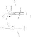
- Fig. 3 is a cross-sectional side view of a single cleaning tube 300 and a single printing pin 315.
- a flow 305 of cleaning fluid, i.e ., wash fluid, up the tube 300 provides an individual fountain 310 for an individual pin 315 to be washed.
- each pin has an independent supply of uncontaminated wash fluid.
- the tubes can be designed to increase or maximize the delivery of uncontaminated fluid while reducing or minimizing the quantity of fluid used. Flow of uncontaminated material is delivered precisely to the surfaces to be cleaned, thus reducing the amount of fluid otherwise needed.
- the placement of the tubes 115 is such that there is sufficient spacing between the tubes 115 so that all waste fluid runs down the sides of the tubes 115 without mixing with either the waste fluids or wash fluids of adjacent tubes. In this manner, the possibility of tube-to-tube cross contamination is reduced, allowing for lower fluid flow rates to be used than would be possible without this drain path.
- Fig. 4 is a side view of a drain end 400 of the single cleaning tube 300 of Fig. 3 incorporating a drain feature.
- Such features can be, but are not limited to, a notch 405 in an upper lip 410 of the tube 300.
- the surface finish of the tube 300 can be manipulated to work against the cleaning fluid's surface tension and enhance flow down the outside of the tube. Examples of such treatments are bead blasting and grit blasting.
- chemical deposition can be applied to similarly enhance the hydrophilic properties of the tubes 115.
- a chemical deposition can be applied to enhance the hydrophobic properties of the tubes 115, depending on the cleaning fluid employed. These treatments need not be applied uniformly, but could be applied over controlled paths to enhance waste fluid flow along desired paths.
- the features and treatments incorporated into the tubes can be preferentially oriented such that waste fluid from one tube is directed toward the controlled waste path of an adjacent tube, thus allowing closer spacing between tubes without mixing adjacent tube wash and waste fluids.
- Fig. 5 is a cross-sectional side view of the cleaning tube 300 with a flow restriction feature 500 in a fluid exit end 505 of the tube 300.
- Two examples of the flow restriction feature are shown in Fig. 5 .
- a first illustrative example is one in which the inner diameter of the tube is restricted by a swage 510 to create sections of higher fluid velocity at particular points along the length of the tube. The swage 510 is created by reducing the diameter of the tube 300. The swage 510 is located at a position along the tube 300 to correspond to the head of the pin to be cleaned.
- a second illustrative example is one in which a flow restrictor 515 is installed in the tube 300.
- the flow restrictor 515 narrows the tube's diameter at a position along the tube 300 to correspond to the head of the pin to be cleaned.
- the flow restriction feature 500 is located to correspond to a position other than the head of the pin, e.g., in-front of or behind the head of the pin along the pin's length.
- a swirl pattern could be etched on the inner surface of the tube or the surface of the flow restrictor 515 near the position that corresponds to the head of the pin to be cleaned.
- a portion of the tube 300 or flow restrictor 515 could be roughened to cause turbulence in the region in which the head of the pin lies. The addition of rotation or turbulence in the cleaning fluid can aid in the cleaning of the pins.
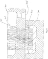
- Fig. 6 is a cross-sectional side view of a multi-chambered wash station 600.
- Wash station 600 is similar to the implementation described above in conjunction with Fig. 1 and has a lower chamber 605, and drain basin 610, cleaning tubes 615, and holds a cleaning fluid 620 in the lower chamber 605.
- Wash station 600 also has a vent tube 625.
- Transient fluctuations in the level of the cleaning fluid 620 in the lower chamber 605 can occur due to, e.g., variations in the pumped fluid flow rate, bubbles in the fluid source supply lines entering the lower chamber 605, and/or mechanical vibrations in the wash station structure. During such disturbances, the level of the cleaning fluid 620 can momentarily drop below the level of the one of the tubes 615. By exposing the bottom opening of one of the tubes 615, trapped air 630 escapes through the top of the tube, thereby depressurizing the lower chamber 605. This causes an interruption in the fluid flow through most, if not all, of the tubes 615.
- working tube as used herein is a tube used to clean pins
- cleaning fluid can become entrained in the escaping air. This, in turn, can cause cleaning fluid to be sprayed out of the outlet end of the tube as the tube inlet is alternately covered and uncovered by the cleaning fluid.
- the sprayed cleaning fluid can cause contamination of pins and/or other equipment.
- the inlet of the vent tube 625 is set at a height that is higher than any of the working tubes 615 (relative to the reference plane described above). In this way, the level of the cleaning fluid 620 in the lower chamber 605 is maintained above the inlet ends of the working tubes 615. Using the same principles described above, the height of the cleaning fluid 620 in the lower chamber 605 rises to the level set by the highest tube, which is now the vent tube 625. In the presence of fluid level fluctuations, the inlet ends of the working tubes 615 do not become uncovered, and therefore, the upward spray of cleaning fluid is avoided.
- the vent tube 625 can spray upward, but it is positioned such that it sprays in a non-detrimental direction.
- Fig. 7 is a cross-sectional side view of the multi-chambered wash station 600 of Fig. 6 , in which the vent tube 625 is fitted with an optional curved outlet end 700.
- the curved outlet end 700 directs the potential spray away from the critical surfaces to be washed.
- the curved outlet end can be positioned to vent directly into one or more waste holes 705.
- Fig. 8 is a cross-sectional side view of the multi-chambered wash station 600 of Fig. 6 , in which the vent tube 625 includes a cap 715. The cap 715 directs potential spray sideways into drain basin 710.
- vent tube 625 can include a wire 720 that is disposed within and along the approximate central axis of vent tube 625. The wire 720 disrupts the surface tension of any fluid within vent tube 625. The wire 720 reduces the likelihood that fluid will clog the vent tube 625 after fluid has vented through the vent tube 625.
- Fig. 9 is a top view of a multiple wash fluid cleaning system 800 employing one or more multi-chambered wash stations. Any of the multi-chambered wash station implementations described above can be used in cleaning system 800.
- the cleaning system 800 uses two multi-chambered wash stations. A first wash station 805 uses a first wash fluid, and a second wash station 810 uses a second wash fluid. Multiple fluid wash sequences are executed by alternatively entering working tubes 815 for the first wash station and then entering working tubes 820 for the second wash station. This multiplicity of fluids is not limited to two; nor is the sequence limited to alternating back and forth between the fluids.
- Cleaning system 800 can be implemented by motion of the pins as well as the described motion of the wash station.
- one working tube is described as being dedicated to a corresponding one pin to be cleaned. If, however, there are more pins in a given printing array to be cleaned than working tubes available, the wash stations and/or cleaning systems described above can incorporate motion, either of the tubes or of the pins, by an increment smaller than the spacing between working tubes.
- Fig. 10 which includes Figs. 10a-10c , is a side view of an arrangement of cleaning tubes for an interlaced cleaning system 900.
- Cleaning system 900 has a first row of working tubes 905 and a second row of working tubes 910.
- the spacing between the first and second rows of working tubes is greater than the spacing of rows of pins 915 in an array to be cleaned. All pins of the array can be cleaned using the interlaced cleaning sequence illustrated Figs. 10a-10c .
- the interlaced cleaning sequence provides for certain rows of pins to be cleaned in one wash cycle, while adjacent rows of pins are cleaned in the next cycle by moving either the pins or the cleaning tubes so as to mate the pins to the cleaning tubes.
- Working tubes can be set apart from each other by any integer increment (i.e., integer multiple) of the pin spacing. Such an embodiment is useful for use with, for example, printing arrays having a relatively large number of pins, e.g., 192 pins, 384 pins, 1536 pins, and greater.
Landscapes
- Chemical & Material Sciences (AREA)
- Health & Medical Sciences (AREA)
- General Health & Medical Sciences (AREA)
- Life Sciences & Earth Sciences (AREA)
- Analytical Chemistry (AREA)
- Biochemistry (AREA)
- Physics & Mathematics (AREA)
- General Physics & Mathematics (AREA)
- Immunology (AREA)
- Pathology (AREA)
- Clinical Laboratory Science (AREA)
- Chemical Kinetics & Catalysis (AREA)
- Cleaning In General (AREA)
- Cleaning By Liquid Or Steam (AREA)
- Cleaning And De-Greasing Of Metallic Materials By Chemical Methods (AREA)
Priority Applications (1)
| Application Number | Priority Date | Filing Date | Title |
|---|---|---|---|
| EP17150710.6A EP3175931A1 (en) | 2007-10-17 | 2008-10-16 | Continual flow pin washer |
Applications Claiming Priority (2)
| Application Number | Priority Date | Filing Date | Title |
|---|---|---|---|
| US98062807P | 2007-10-17 | 2007-10-17 | |
| PCT/US2008/080122 WO2009052260A1 (en) | 2007-10-17 | 2008-10-16 | Continual flow pin washer |
Related Child Applications (2)
| Application Number | Title | Priority Date | Filing Date |
|---|---|---|---|
| EP17150710.6A Division-Into EP3175931A1 (en) | 2007-10-17 | 2008-10-16 | Continual flow pin washer |
| EP17150710.6A Division EP3175931A1 (en) | 2007-10-17 | 2008-10-16 | Continual flow pin washer |
Publications (3)
| Publication Number | Publication Date |
|---|---|
| EP2205365A1 EP2205365A1 (en) | 2010-07-14 |
| EP2205365A4 EP2205365A4 (en) | 2014-02-19 |
| EP2205365B1 true EP2205365B1 (en) | 2017-02-22 |
Family
ID=40562225
Family Applications (2)
| Application Number | Title | Priority Date | Filing Date |
|---|---|---|---|
| EP08839397.0A Not-in-force EP2205365B1 (en) | 2007-10-17 | 2008-10-16 | Continual flow pin washer |
| EP17150710.6A Withdrawn EP3175931A1 (en) | 2007-10-17 | 2008-10-16 | Continual flow pin washer |
Family Applications After (1)
| Application Number | Title | Priority Date | Filing Date |
|---|---|---|---|
| EP17150710.6A Withdrawn EP3175931A1 (en) | 2007-10-17 | 2008-10-16 | Continual flow pin washer |
Country Status (8)
| Country | Link |
|---|---|
| US (3) | US8020571B2 (https=) |
| EP (2) | EP2205365B1 (https=) |
| JP (2) | JP5243547B2 (https=) |
| AU (1) | AU2008312470B2 (https=) |
| CA (1) | CA2702925C (https=) |
| DK (1) | DK2205365T3 (https=) |
| ES (1) | ES2618585T3 (https=) |
| WO (1) | WO2009052260A1 (https=) |
Families Citing this family (8)
| Publication number | Priority date | Publication date | Assignee | Title |
|---|---|---|---|---|
| EP2205365B1 (en) * | 2007-10-17 | 2017-02-22 | Aushon Biosystems | Continual flow pin washer |
| US8246751B2 (en) | 2010-10-01 | 2012-08-21 | General Electric Company | Pulsed detonation cleaning systems and methods |
| WO2013074643A2 (en) | 2011-11-14 | 2013-05-23 | Aushon Biosystems, Inc. | Systems and methods to enhance consistency of assay performance |
| US10562032B2 (en) | 2017-05-26 | 2020-02-18 | Aushon Biosystems, Inc. | Systems and methods for automatic plate washing |
| US11686730B2 (en) | 2020-04-30 | 2023-06-27 | Quanterix Corporation | Quantitative antibody test |
| US12203953B2 (en) | 2020-07-29 | 2025-01-21 | Siemens Healthcare Diagnostics Inc. | Helix wash station that augments the fluid dynamics associated with clinical chemistry and immunoassay probe cleaning |
| EP4330691A1 (en) * | 2021-04-27 | 2024-03-06 | Life Technologies Corporation | Sample injection probe washing |
| DE102024101291B4 (de) * | 2023-01-20 | 2025-08-14 | Miele & Cie. Kg | Reinigungseinrichtung |
Family Cites Families (25)
| Publication number | Priority date | Publication date | Assignee | Title |
|---|---|---|---|---|
| JPS57190467U (https=) * | 1981-05-29 | 1982-12-02 | ||
| JPS58163870U (ja) * | 1982-04-28 | 1983-10-31 | オリンパス光学工業株式会社 | 自動分析機のノズル洗浄槽 |
| US4730631A (en) * | 1985-07-22 | 1988-03-15 | Sequoia-Turner Corporation | Probe wash station |
| JPS62195920U (https=) * | 1986-05-31 | 1987-12-12 | ||
| GR871619B (en) * | 1986-10-31 | 1988-03-03 | Genetic Systems Corp | Automated patient sample analysis instrument |
| JPH01209372A (ja) * | 1988-02-18 | 1989-08-23 | Toshiba Corp | 自動化学分析装置の洗浄装置 |
| FI84764C (fi) * | 1989-09-25 | 1992-01-10 | Labsystems Oy | Spolningsanordning. |
| DD295913A5 (de) * | 1990-06-26 | 1991-11-14 | Mlw Pruefgeraete-Werk Medingen/Sitz Freital,De | Vorrichtung zur spuelung eines probenahmesystems |
| JPH04105066A (ja) * | 1990-08-24 | 1992-04-07 | Olympus Optical Co Ltd | プローブ洗浄容器 |
| JPH05126836A (ja) * | 1991-10-31 | 1993-05-21 | Toshiba Corp | プローブ洗浄槽 |
| JP2890089B2 (ja) * | 1993-09-06 | 1999-05-10 | 東京エレクトロン株式会社 | 処理装置 |
| CA2132270A1 (en) * | 1993-10-28 | 1995-04-29 | Erich Lerch | Automatic pipetting apparatus having a cleaning device |
| CA2167471A1 (en) * | 1995-01-31 | 1996-08-01 | Johnson & Johnson Clinical Diagnostics, Inc. | Probe wash device |
| JP2001504749A (ja) * | 1995-07-14 | 2001-04-10 | ベックマン コールター,インコーポレイティド | ピペットプローブを洗浄するための装置及び方法 |
| US5803987A (en) * | 1997-01-17 | 1998-09-08 | Warner-Lambert Company | Multi-tip wash station for robot |
| US20020059945A1 (en) * | 1998-05-29 | 2002-05-23 | Romaine Maiefski | Sample wash station assembly |
| US5976470A (en) * | 1998-05-29 | 1999-11-02 | Ontogen Corporation | Sample wash station assembly |
| US6325080B1 (en) * | 1999-02-10 | 2001-12-04 | Georg Held | Cleaning of medical devices avoiding recontamination |
| DE19934090A1 (de) * | 1999-07-19 | 2001-02-08 | Cybio Instr Gmbh | Spülwannensystem |
| US6170494B1 (en) * | 1999-11-12 | 2001-01-09 | Advanced Micro Devices, Inc. | Method for automatically cleaning resist nozzle |
| WO2002066151A2 (en) | 2001-01-26 | 2002-08-29 | Symyx Technologies, Inc. | Apparatus and methods for parallel processing of multiple reaction mixtures |
| US7648678B2 (en) | 2002-12-20 | 2010-01-19 | Dako Denmark A/S | Method and system for pretreatment of tissue slides |
| US6955180B2 (en) | 2003-01-06 | 2005-10-18 | Spex Certiprep, Inc. | Pipette washer |
| DK2322278T3 (en) | 2003-10-24 | 2017-04-10 | Aushon Biosystems Inc | Apparatus and method for dispensing liquid, semi-solid and solid samples |
| EP2205365B1 (en) * | 2007-10-17 | 2017-02-22 | Aushon Biosystems | Continual flow pin washer |
-
2008
- 2008-10-16 EP EP08839397.0A patent/EP2205365B1/en not_active Not-in-force
- 2008-10-16 ES ES08839397.0T patent/ES2618585T3/es active Active
- 2008-10-16 US US12/252,487 patent/US8020571B2/en active Active
- 2008-10-16 DK DK08839397.0T patent/DK2205365T3/en active
- 2008-10-16 WO PCT/US2008/080122 patent/WO2009052260A1/en not_active Ceased
- 2008-10-16 EP EP17150710.6A patent/EP3175931A1/en not_active Withdrawn
- 2008-10-16 CA CA2702925A patent/CA2702925C/en not_active Expired - Fee Related
- 2008-10-16 AU AU2008312470A patent/AU2008312470B2/en not_active Ceased
- 2008-10-16 JP JP2010530104A patent/JP5243547B2/ja active Active
-
2011
- 2011-09-14 US US13/232,593 patent/US8246760B2/en not_active Expired - Fee Related
-
2012
- 2012-08-20 US US13/589,671 patent/US8679262B2/en not_active Expired - Fee Related
-
2013
- 2013-04-03 JP JP2013077612A patent/JP2013139037A/ja active Pending
Non-Patent Citations (1)
| Title |
|---|
| None * |
Also Published As
| Publication number | Publication date |
|---|---|
| WO2009052260A1 (en) | 2009-04-23 |
| US8679262B2 (en) | 2014-03-25 |
| US8246760B2 (en) | 2012-08-21 |
| JP2013139037A (ja) | 2013-07-18 |
| AU2008312470B2 (en) | 2013-07-11 |
| US20120000493A1 (en) | 2012-01-05 |
| CA2702925C (en) | 2016-09-20 |
| ES2618585T3 (es) | 2017-06-21 |
| EP2205365A1 (en) | 2010-07-14 |
| JP5243547B2 (ja) | 2013-07-24 |
| US8020571B2 (en) | 2011-09-20 |
| JP2011500319A (ja) | 2011-01-06 |
| AU2008312470A1 (en) | 2009-04-23 |
| US20130061880A1 (en) | 2013-03-14 |
| CA2702925A1 (en) | 2009-04-23 |
| EP2205365A4 (en) | 2014-02-19 |
| EP3175931A1 (en) | 2017-06-07 |
| DK2205365T3 (en) | 2017-03-20 |
| US20090101175A1 (en) | 2009-04-23 |
Similar Documents
| Publication | Publication Date | Title |
|---|---|---|
| US8679262B2 (en) | Continual flow pin washer | |
| KR102023328B1 (ko) | 표면 처리 장치 | |
| CN101505885B (zh) | 用于在清洁机中处理瓶子或类似容器的方法以及清洁机 | |
| EP2501499B1 (en) | Apparatus, systems, and methods adapted to rinse and dry clinical analyzer sample probes | |
| US6511849B1 (en) | Microarrays of biological materials | |
| EP3046688B1 (en) | Ultrasonic cleaning apparatus and method | |
| KR20080069676A (ko) | 물체, 특히 얇은 디스크를 세정하기 위한 장치 및 방법 | |
| EP0825446B1 (en) | Pipette-washing device for automatic biochemical analyzer | |
| US20240359201A1 (en) | Dispenser device, centrifuge comprising such a dispenser device, and method for cleaning dispenser nozzles | |
| CN109716142A (zh) | 自动分析装置 | |
| AU2012265873A1 (en) | Ink- jet printing device | |
| HK1146010A (en) | Continual flow pin washer | |
| HK1146010B (en) | Continual flow pin washer | |
| JP2000329771A (ja) | 分注装置 | |
| EP1656996A1 (en) | Agitated flotation apparatus for cleaning fibrous suspensions dispersed in liquids. | |
| AU2013203421A1 (en) | Continual flow pin washer | |
| JP2519381B2 (ja) | 流体処理装置 | |
| US20210039127A1 (en) | Cleaning device and corresponding method | |
| JP6306128B2 (ja) | 表面処理装置 | |
| US20170120587A1 (en) | Inkjet head and coating apparatus using same | |
| KR101767442B1 (ko) | 폐수 정화용 마이크로 버블 디퓨져 | |
| US12203953B2 (en) | Helix wash station that augments the fluid dynamics associated with clinical chemistry and immunoassay probe cleaning | |
| CN217569213U (zh) | 一种集成式显影槽喷头及显影设备 | |
| JPH09225417A (ja) | シャワー式洗浄装置 | |
| HK1170980B (en) | Apparatus, systems, and methods adapted to rinse and dry clinical analyzer sample probes |
Legal Events
| Date | Code | Title | Description |
|---|---|---|---|
| PUAI | Public reference made under article 153(3) epc to a published international application that has entered the european phase |
Free format text: ORIGINAL CODE: 0009012 |
|
| 17P | Request for examination filed |
Effective date: 20100428 |
|
| AK | Designated contracting states |
Kind code of ref document: A1 Designated state(s): AT BE BG CH CY CZ DE DK EE ES FI FR GB GR HR HU IE IS IT LI LT LU LV MC MT NL NO PL PT RO SE SI SK TR |
|
| AX | Request for extension of the european patent |
Extension state: AL BA MK RS |
|
| DAX | Request for extension of the european patent (deleted) | ||
| REG | Reference to a national code |
Ref country code: HK Ref legal event code: DE Ref document number: 1146010 Country of ref document: HK |
|
| A4 | Supplementary search report drawn up and despatched |
Effective date: 20140122 |
|
| RIC1 | Information provided on ipc code assigned before grant |
Ipc: B08B 3/02 20060101AFI20140116BHEP |
|
| 17Q | First examination report despatched |
Effective date: 20151126 |
|
| GRAP | Despatch of communication of intention to grant a patent |
Free format text: ORIGINAL CODE: EPIDOSNIGR1 |
|
| INTG | Intention to grant announced |
Effective date: 20160909 |
|
| RIN1 | Information on inventor provided before grant (corrected) |
Inventor name: BRADBURY, DAVE Inventor name: BUKYS, ALBERT Inventor name: HONKANEN, PETER |
|
| GRAS | Grant fee paid |
Free format text: ORIGINAL CODE: EPIDOSNIGR3 |
|
| GRAA | (expected) grant |
Free format text: ORIGINAL CODE: 0009210 |
|
| AK | Designated contracting states |
Kind code of ref document: B1 Designated state(s): AT BE BG CH CY CZ DE DK EE ES FI FR GB GR HR HU IE IS IT LI LT LU LV MC MT NL NO PL PT RO SE SI SK TR |
|
| REG | Reference to a national code |
Ref country code: GB Ref legal event code: FG4D |
|
| REG | Reference to a national code |
Ref country code: CH Ref legal event code: EP |
|
| REG | Reference to a national code |
Ref country code: AT Ref legal event code: REF Ref document number: 868840 Country of ref document: AT Kind code of ref document: T Effective date: 20170315 Ref country code: NL Ref legal event code: FP |
|
| REG | Reference to a national code |
Ref country code: DK Ref legal event code: T3 Effective date: 20170314 |
|
| REG | Reference to a national code |
Ref country code: IE Ref legal event code: FG4D |
|
| REG | Reference to a national code |
Ref country code: SE Ref legal event code: TRGR |
|
| REG | Reference to a national code |
Ref country code: CH Ref legal event code: NV Representative=s name: MICHELI AND CIE SA, CH |
|
| REG | Reference to a national code |
Ref country code: DE Ref legal event code: R096 Ref document number: 602008048854 Country of ref document: DE |
|
| REG | Reference to a national code |
Ref country code: NO Ref legal event code: T2 Effective date: 20170222 |
|
| REG | Reference to a national code |
Ref country code: ES Ref legal event code: FG2A Ref document number: 2618585 Country of ref document: ES Kind code of ref document: T3 Effective date: 20170621 |
|
| REG | Reference to a national code |
Ref country code: LT Ref legal event code: MG4D |
|
| PG25 | Lapsed in a contracting state [announced via postgrant information from national office to epo] |
Ref country code: HR Free format text: LAPSE BECAUSE OF FAILURE TO SUBMIT A TRANSLATION OF THE DESCRIPTION OR TO PAY THE FEE WITHIN THE PRESCRIBED TIME-LIMIT Effective date: 20170222 Ref country code: LT Free format text: LAPSE BECAUSE OF FAILURE TO SUBMIT A TRANSLATION OF THE DESCRIPTION OR TO PAY THE FEE WITHIN THE PRESCRIBED TIME-LIMIT Effective date: 20170222 Ref country code: GR Free format text: LAPSE BECAUSE OF FAILURE TO SUBMIT A TRANSLATION OF THE DESCRIPTION OR TO PAY THE FEE WITHIN THE PRESCRIBED TIME-LIMIT Effective date: 20170523 |
|
| PG25 | Lapsed in a contracting state [announced via postgrant information from national office to epo] |
Ref country code: PT Free format text: LAPSE BECAUSE OF FAILURE TO SUBMIT A TRANSLATION OF THE DESCRIPTION OR TO PAY THE FEE WITHIN THE PRESCRIBED TIME-LIMIT Effective date: 20170622 Ref country code: BG Free format text: LAPSE BECAUSE OF FAILURE TO SUBMIT A TRANSLATION OF THE DESCRIPTION OR TO PAY THE FEE WITHIN THE PRESCRIBED TIME-LIMIT Effective date: 20170522 Ref country code: LV Free format text: LAPSE BECAUSE OF FAILURE TO SUBMIT A TRANSLATION OF THE DESCRIPTION OR TO PAY THE FEE WITHIN THE PRESCRIBED TIME-LIMIT Effective date: 20170222 |
|
| REG | Reference to a national code |
Ref country code: FR Ref legal event code: PLFP Year of fee payment: 10 |
|
| PG25 | Lapsed in a contracting state [announced via postgrant information from national office to epo] |
Ref country code: RO Free format text: LAPSE BECAUSE OF FAILURE TO SUBMIT A TRANSLATION OF THE DESCRIPTION OR TO PAY THE FEE WITHIN THE PRESCRIBED TIME-LIMIT Effective date: 20170222 Ref country code: SK Free format text: LAPSE BECAUSE OF FAILURE TO SUBMIT A TRANSLATION OF THE DESCRIPTION OR TO PAY THE FEE WITHIN THE PRESCRIBED TIME-LIMIT Effective date: 20170222 Ref country code: CZ Free format text: LAPSE BECAUSE OF FAILURE TO SUBMIT A TRANSLATION OF THE DESCRIPTION OR TO PAY THE FEE WITHIN THE PRESCRIBED TIME-LIMIT Effective date: 20170222 Ref country code: EE Free format text: LAPSE BECAUSE OF FAILURE TO SUBMIT A TRANSLATION OF THE DESCRIPTION OR TO PAY THE FEE WITHIN THE PRESCRIBED TIME-LIMIT Effective date: 20170222 |
|
| REG | Reference to a national code |
Ref country code: DE Ref legal event code: R097 Ref document number: 602008048854 Country of ref document: DE |
|
| PG25 | Lapsed in a contracting state [announced via postgrant information from national office to epo] |
Ref country code: PL Free format text: LAPSE BECAUSE OF FAILURE TO SUBMIT A TRANSLATION OF THE DESCRIPTION OR TO PAY THE FEE WITHIN THE PRESCRIBED TIME-LIMIT Effective date: 20170222 |
|
| PLBE | No opposition filed within time limit |
Free format text: ORIGINAL CODE: 0009261 |
|
| STAA | Information on the status of an ep patent application or granted ep patent |
Free format text: STATUS: NO OPPOSITION FILED WITHIN TIME LIMIT |
|
| 26N | No opposition filed |
Effective date: 20171123 |
|
| PGFP | Annual fee paid to national office [announced via postgrant information from national office to epo] |
Ref country code: FR Payment date: 20171025 Year of fee payment: 10 |
|
| PG25 | Lapsed in a contracting state [announced via postgrant information from national office to epo] |
Ref country code: SI Free format text: LAPSE BECAUSE OF FAILURE TO SUBMIT A TRANSLATION OF THE DESCRIPTION OR TO PAY THE FEE WITHIN THE PRESCRIBED TIME-LIMIT Effective date: 20170222 |
|
| REG | Reference to a national code |
Ref country code: HK Ref legal event code: GR Ref document number: 1146010 Country of ref document: HK |
|
| PG25 | Lapsed in a contracting state [announced via postgrant information from national office to epo] |
Ref country code: MC Free format text: LAPSE BECAUSE OF FAILURE TO SUBMIT A TRANSLATION OF THE DESCRIPTION OR TO PAY THE FEE WITHIN THE PRESCRIBED TIME-LIMIT Effective date: 20170222 |
|
| PG25 | Lapsed in a contracting state [announced via postgrant information from national office to epo] |
Ref country code: LU Free format text: LAPSE BECAUSE OF NON-PAYMENT OF DUE FEES Effective date: 20171016 |
|
| PG25 | Lapsed in a contracting state [announced via postgrant information from national office to epo] |
Ref country code: MT Free format text: LAPSE BECAUSE OF NON-PAYMENT OF DUE FEES Effective date: 20171016 |
|
| REG | Reference to a national code |
Ref country code: AT Ref legal event code: UEP Ref document number: 868840 Country of ref document: AT Kind code of ref document: T Effective date: 20170222 |
|
| PG25 | Lapsed in a contracting state [announced via postgrant information from national office to epo] |
Ref country code: HU Free format text: LAPSE BECAUSE OF FAILURE TO SUBMIT A TRANSLATION OF THE DESCRIPTION OR TO PAY THE FEE WITHIN THE PRESCRIBED TIME-LIMIT; INVALID AB INITIO Effective date: 20081016 |
|
| PG25 | Lapsed in a contracting state [announced via postgrant information from national office to epo] |
Ref country code: FR Free format text: LAPSE BECAUSE OF NON-PAYMENT OF DUE FEES Effective date: 20181031 |
|
| PG25 | Lapsed in a contracting state [announced via postgrant information from national office to epo] |
Ref country code: CY Free format text: LAPSE BECAUSE OF NON-PAYMENT OF DUE FEES Effective date: 20170222 |
|
| PGFP | Annual fee paid to national office [announced via postgrant information from national office to epo] |
Ref country code: NL Payment date: 20191026 Year of fee payment: 12 Ref country code: DE Payment date: 20191029 Year of fee payment: 12 Ref country code: SE Payment date: 20191029 Year of fee payment: 12 Ref country code: NO Payment date: 20191029 Year of fee payment: 12 Ref country code: FI Payment date: 20191029 Year of fee payment: 12 Ref country code: IE Payment date: 20191028 Year of fee payment: 12 |
|
| PGFP | Annual fee paid to national office [announced via postgrant information from national office to epo] |
Ref country code: BE Payment date: 20191028 Year of fee payment: 12 Ref country code: ES Payment date: 20191104 Year of fee payment: 12 Ref country code: IT Payment date: 20191023 Year of fee payment: 12 Ref country code: DK Payment date: 20191029 Year of fee payment: 12 |
|
| PG25 | Lapsed in a contracting state [announced via postgrant information from national office to epo] |
Ref country code: TR Free format text: LAPSE BECAUSE OF FAILURE TO SUBMIT A TRANSLATION OF THE DESCRIPTION OR TO PAY THE FEE WITHIN THE PRESCRIBED TIME-LIMIT Effective date: 20170222 |
|
| PGFP | Annual fee paid to national office [announced via postgrant information from national office to epo] |
Ref country code: AT Payment date: 20191002 Year of fee payment: 12 Ref country code: CH Payment date: 20191104 Year of fee payment: 12 |
|
| PGFP | Annual fee paid to national office [announced via postgrant information from national office to epo] |
Ref country code: GB Payment date: 20191028 Year of fee payment: 12 |
|
| PG25 | Lapsed in a contracting state [announced via postgrant information from national office to epo] |
Ref country code: IS Free format text: LAPSE BECAUSE OF FAILURE TO SUBMIT A TRANSLATION OF THE DESCRIPTION OR TO PAY THE FEE WITHIN THE PRESCRIBED TIME-LIMIT Effective date: 20170622 |
|
| REG | Reference to a national code |
Ref country code: DE Ref legal event code: R119 Ref document number: 602008048854 Country of ref document: DE |
|
| REG | Reference to a national code |
Ref country code: NO Ref legal event code: MMEP Ref country code: DK Ref legal event code: EBP Effective date: 20201031 |
|
| REG | Reference to a national code |
Ref country code: CH Ref legal event code: PL Ref country code: FI Ref legal event code: MAE |
|
| REG | Reference to a national code |
Ref country code: SE Ref legal event code: EUG |
|
| REG | Reference to a national code |
Ref country code: NL Ref legal event code: MM Effective date: 20201101 |
|
| REG | Reference to a national code |
Ref country code: AT Ref legal event code: MM01 Ref document number: 868840 Country of ref document: AT Kind code of ref document: T Effective date: 20201016 |
|
| GBPC | Gb: european patent ceased through non-payment of renewal fee |
Effective date: 20201016 |
|
| REG | Reference to a national code |
Ref country code: BE Ref legal event code: MM Effective date: 20201031 |
|
| PG25 | Lapsed in a contracting state [announced via postgrant information from national office to epo] |
Ref country code: NL Free format text: LAPSE BECAUSE OF NON-PAYMENT OF DUE FEES Effective date: 20201101 Ref country code: NO Free format text: LAPSE BECAUSE OF NON-PAYMENT OF DUE FEES Effective date: 20201031 Ref country code: DE Free format text: LAPSE BECAUSE OF NON-PAYMENT OF DUE FEES Effective date: 20210501 Ref country code: FI Free format text: LAPSE BECAUSE OF NON-PAYMENT OF DUE FEES Effective date: 20201016 |
|
| PG25 | Lapsed in a contracting state [announced via postgrant information from national office to epo] |
Ref country code: GB Free format text: LAPSE BECAUSE OF NON-PAYMENT OF DUE FEES Effective date: 20201016 Ref country code: LI Free format text: LAPSE BECAUSE OF NON-PAYMENT OF DUE FEES Effective date: 20201031 Ref country code: SE Free format text: LAPSE BECAUSE OF NON-PAYMENT OF DUE FEES Effective date: 20201017 Ref country code: CH Free format text: LAPSE BECAUSE OF NON-PAYMENT OF DUE FEES Effective date: 20201031 Ref country code: BE Free format text: LAPSE BECAUSE OF NON-PAYMENT OF DUE FEES Effective date: 20201031 Ref country code: AT Free format text: LAPSE BECAUSE OF NON-PAYMENT OF DUE FEES Effective date: 20201016 |
|
| PG25 | Lapsed in a contracting state [announced via postgrant information from national office to epo] |
Ref country code: IE Free format text: LAPSE BECAUSE OF NON-PAYMENT OF DUE FEES Effective date: 20201016 Ref country code: IT Free format text: LAPSE BECAUSE OF NON-PAYMENT OF DUE FEES Effective date: 20201016 |
|
| PG25 | Lapsed in a contracting state [announced via postgrant information from national office to epo] |
Ref country code: DK Free format text: LAPSE BECAUSE OF NON-PAYMENT OF DUE FEES Effective date: 20201031 |
|
| REG | Reference to a national code |
Ref country code: ES Ref legal event code: FD2A Effective date: 20220128 |
|
| PG25 | Lapsed in a contracting state [announced via postgrant information from national office to epo] |
Ref country code: ES Free format text: LAPSE BECAUSE OF NON-PAYMENT OF DUE FEES Effective date: 20201017 |