EP2202851A2 - Steckdose mit Lösemechanismus - Google Patents
Steckdose mit Lösemechanismus Download PDFInfo
- Publication number
- EP2202851A2 EP2202851A2 EP09015903A EP09015903A EP2202851A2 EP 2202851 A2 EP2202851 A2 EP 2202851A2 EP 09015903 A EP09015903 A EP 09015903A EP 09015903 A EP09015903 A EP 09015903A EP 2202851 A2 EP2202851 A2 EP 2202851A2
- Authority
- EP
- European Patent Office
- Prior art keywords
- socket
- socket according
- plug
- solvent
- release mechanism
- Prior art date
- Legal status (The legal status is an assumption and is not a legal conclusion. Google has not performed a legal analysis and makes no representation as to the accuracy of the status listed.)
- Granted
Links
Images


Classifications
-
- H—ELECTRICITY
- H01—ELECTRIC ELEMENTS
- H01R—ELECTRICALLY-CONDUCTIVE CONNECTIONS; STRUCTURAL ASSOCIATIONS OF A PLURALITY OF MUTUALLY-INSULATED ELECTRICAL CONNECTING ELEMENTS; COUPLING DEVICES; CURRENT COLLECTORS
- H01R13/00—Details of coupling devices of the kinds covered by groups H01R12/70 or H01R24/00 - H01R33/00
- H01R13/62—Means for facilitating engagement or disengagement of coupling parts or for holding them in engagement
- H01R13/629—Additional means for facilitating engagement or disengagement of coupling parts, e.g. aligning or guiding means, levers, gas pressure electrical locking indicators, manufacturing tolerances
- H01R13/633—Additional means for facilitating engagement or disengagement of coupling parts, e.g. aligning or guiding means, levers, gas pressure electrical locking indicators, manufacturing tolerances for disengagement only
- H01R13/635—Additional means for facilitating engagement or disengagement of coupling parts, e.g. aligning or guiding means, levers, gas pressure electrical locking indicators, manufacturing tolerances for disengagement only by mechanical pressure, e.g. spring force
-
- H—ELECTRICITY
- H01—ELECTRIC ELEMENTS
- H01R—ELECTRICALLY-CONDUCTIVE CONNECTIONS; STRUCTURAL ASSOCIATIONS OF A PLURALITY OF MUTUALLY-INSULATED ELECTRICAL CONNECTING ELEMENTS; COUPLING DEVICES; CURRENT COLLECTORS
- H01R13/00—Details of coupling devices of the kinds covered by groups H01R12/70 or H01R24/00 - H01R33/00
- H01R13/648—Protective earth or shield arrangements on coupling devices, e.g. anti-static shielding
- H01R13/655—Protective earth or shield arrangements on coupling devices, e.g. anti-static shielding with earth brace
-
- H—ELECTRICITY
- H01—ELECTRIC ELEMENTS
- H01R—ELECTRICALLY-CONDUCTIVE CONNECTIONS; STRUCTURAL ASSOCIATIONS OF A PLURALITY OF MUTUALLY-INSULATED ELECTRICAL CONNECTING ELEMENTS; COUPLING DEVICES; CURRENT COLLECTORS
- H01R24/00—Two-part coupling devices, or either of their cooperating parts, characterised by their overall structure
- H01R24/76—Two-part coupling devices, or either of their cooperating parts, characterised by their overall structure with sockets, clips or analogous contacts and secured to apparatus or structure, e.g. to a wall
- H01R24/78—Two-part coupling devices, or either of their cooperating parts, characterised by their overall structure with sockets, clips or analogous contacts and secured to apparatus or structure, e.g. to a wall with additional earth or shield contacts
-
- H—ELECTRICITY
- H01—ELECTRIC ELEMENTS
- H01R—ELECTRICALLY-CONDUCTIVE CONNECTIONS; STRUCTURAL ASSOCIATIONS OF A PLURALITY OF MUTUALLY-INSULATED ELECTRICAL CONNECTING ELEMENTS; COUPLING DEVICES; CURRENT COLLECTORS
- H01R13/00—Details of coupling devices of the kinds covered by groups H01R12/70 or H01R24/00 - H01R33/00
- H01R13/66—Structural association with built-in electrical component
- H01R13/665—Structural association with built-in electrical component with built-in electronic circuit
-
- H—ELECTRICITY
- H01—ELECTRIC ELEMENTS
- H01R—ELECTRICALLY-CONDUCTIVE CONNECTIONS; STRUCTURAL ASSOCIATIONS OF A PLURALITY OF MUTUALLY-INSULATED ELECTRICAL CONNECTING ELEMENTS; COUPLING DEVICES; CURRENT COLLECTORS
- H01R2103/00—Two poles
Definitions
- the invention relates to a socket according to the preamble of claim 1.
- Electrical consumers are often connected detachably to an electrical supply voltage. Such a connection can be made via a plug, which can be plugged into a stationarily arranged socket.
- a mechanical release device can be integrated into a central insert of a socket, which acts axially counter to the plug-in direction of the plug and can be operated by means of a release button. Furthermore, a release ring can be integrated into the central insert, which can be rotated manually while pushing the plug axially out of the socket. The manual rotation is contrary to the user-friendly axial plug and release movement.
- the object of the present invention is therefore to enable a comfortable and user-friendly release of a plug from a socket while maintaining existing structures of the socket.
- the invention according to claim 1 has the advantage that can be dispensed with the manual power by the use of a motor when releasing a plug from a socket and the release of a connector can be greatly facilitated.
- a socket according to the invention is suitable for use in hard to reach places and / or in the area of use of elderly and / or persons with limited health.
- both an electric motor which converts electrical energy fed into a translational or rotational movement, as well as a piezo drive can be understood, which causes a material deformation and thus a usable mechanical movement upon application of an electrical voltage.
- the motor can be connected via contact elements of the socket to a supply voltage.
- a release mechanism can be coupled, which can convert the motor-generated movement into an advantageous mechanical movement for releasing the plug from a central insert of the socket.
- the release mechanism comprises a transmission and at least one mechanically connected solvent, which is movably mounted in the central insert.
- the solvent may act directly or indirectly, for example via a movably mounted part of the central insert, on a plug located in the socket.
- the solvent or solvents may be disposed in the vicinity of contact openings for the plug pins to be used in both bipolar and in the to be able to use the same central insert uniformly over three-pole plugs.
- the solvent can transmit a force generated by the motor evenly and axially to the direction of insertion on the plug, so that the plug can not tilt during the release process.
- a plurality of solvents can be arranged evenly distributed in the central insert, based on the center of the central insert.
- the plug can be pressed out of the central insert by means of a solvent which is movable in a direction opposite to the direction of insertion and / or by means of a solvent acting perpendicular to the direction of insertion.
- a ring rotatably mounted on the central insert can release the plug.
- the release mechanism may include various mechanical components that may be disposed on the central insert and / or on a device base. As mechanical components, for example, levers, shafts, links, pins, gears, racks and / or worm wheels can be used, which may consist of metallic or non-metallic materials.
- the plug can be pressed by the release mechanism in a removal position in which it can be held in the socket and user side can be removed. So it can be avoided that the plug uncontrollably falls out of the socket and, for example, remains difficult to reach behind or under objects.
- an automatic reset of the release mechanism so that the socket can be used immediately.
- spring elements can be used.
- the engine can again in the Move back home position and reset the mechanically coupled release mechanism.
- the release mechanism can also be reset by inserting the plug.
- the engine and parts of the release mechanism are arranged together in a drive unit.
- the assemblies can advantageously be used self-fixing and / or self-contacting. Electrical and / or mechanical interfaces between the assemblies may be uniform, so that different equipment variants are compatible with each other.
- a space-saving arrangement of components the known structure of sockets and recording space for the engine and / or for the release mechanism to be created.
- a receiving space may be formed on or in the front element and / or on or in the device base of the socket.
- the control of the motor can be done via a arranged in the front panel command generator, such. As a button or a switch that releases the supply voltage for the engine.
- a front element equipped can be exchanged for the existing front element.
- the activation of the motor can also be done by means of a remote command transmitter, z. B. by a wireless, such as radio-controlled, operation or by wired bus media.
- the motor-driven release mechanism can be used in both electrical and optical connectors.
- the optical signal may be converted into an electrical signal or a separate electrical power supply may be provided to power the motor.
- the socket 1 can be mounted in an installation housing, not shown, which is fixed in a stationary building wall.
- the socket 1 has a device base 2, the outside a support frame 3 surrounds, which allows the attachment of the socket 1 in the installation housing.
- Front side a multi-part front element 4 is arranged.
- the front element 4 comprises a cup-shaped central insert 5 with contact openings 6 for receiving plug pins of a plug, not shown.
- terminals 7 are arranged for connecting lines of a power supply and associated metallic contact elements 8, in the front of the connector pins can be inserted.
- a grounding bracket 9 is arranged, which serves for the front-side contacting of a ground contact of the plug.
- the socket 1 comprises a motor 10 and a release mechanism 11, which are arranged differently depending on the embodiment.
- the release mechanism 11 has a transmission 12 and solvent 13.
- Fig. 1 Solvents 13 are shown in the form of pins, while in Fig. 2 Solvents 13 are formed as cuboid components of the central insert 5.
- the solvents 13 are arranged in the vicinity of the contact openings 6 in order to use the central insert 5 in both two-pole and three-pole plugs.
- the solvents 13 are guided displaceably on both sides of the contact openings 6 and arranged symmetrically to each other in the central insert 5 to the release of the Plug to avoid tilting.
- the solvents 13 are provided on both sides with end stops, not shown, so that they are arranged captive in the central insert 5.
- the drive unit 14 includes the motor 10, the gear 12 of the release mechanism 11 and electrical components for power supply and control electronics 16 for controlling the motor 10.
- the gear 12 provides the mechanical connection to the solvents 13 in the central insert 5.
- Bottom side terminal contacts 17 are protected against contact out of the drive unit 14, which are electrically contacted with the terminals 7 and / or contact elements 8 in the device base 2 and ensure the electrical supply of the motor 10.
- a commander 18 in the form of a switch is arranged on the central insert 5 in order to switch on the motor 10.
- the connecting lines 19 extend along the central insert 5 and are guided by means of a plug connection 20 in the drive unit 14.
- the engine 10 has a gear 21 on the output side, which transmits the rotational movement to a gear 12.
- the gear 12 comprises a rack 22 guided in the drive unit 14 and a lever 23 mounted in the drive unit 14.
- the lever 23 is guided out of the drive unit 14 and forms a fork 24 which can be mechanically coupled to the solvents 13 in the central insert 5 is.
- the gear 21 meshes with the rack 22, which in turn moves the lever 23 up or down and thus can move the solvent 13 axially in the central insert 5.
- a part of the release mechanism 11 is combined to form an assembly 25, which is arranged on the bottom side of the central insert 5 on the base side.
- the assembly 25 is preferably made flat and latched to the central insert 5.
- a lever 23 is mounted, which is designed on one side and there forms a fork 24 which is mechanically coupled to the solvents 13 in the central insert 5.
- a drive unit 14 arranged on the appliance base 2 has a motor 10, the rotational movement of which is transmitted to the lever 23 in the assembly 25 via a toothed wheel 21 and a rack 22 made of the drive unit 14.
- the rack 22 and the lever 23 are mechanically coupled together.
- the motor 10 is activated via the command transmitter 18 arranged at the front or, alternatively, via a non-illustrated control electronics 16 of the drive unit 14 integrated in the control electronics and wirelessly operable by means of a remote control radio module.
- Both commanders 18 release the voltage supply for the motor 10, so that its rotational movement is transmitted via the gear 12 to the solvent 13.
- the solvents 13 proceed from a retracted position according to Fig. 3 in which a plug can be located in the central insert 5, in an extended position according to Fig. 4 in which the plug can be pushed out of the central insert 5 counter to an insertion direction X, and can remain in a removal position in the central insert 5.
- the control electronics 16 in the drive unit 14 then activates the motor 10 to a reverse movement, so that the mechanically coupled release mechanism 11 automatically returns to the original position Fig. 3 retracts with retracted solvents 13.
Landscapes
- Details Of Connecting Devices For Male And Female Coupling (AREA)
- Motor Or Generator Frames (AREA)
Abstract
Description
- Die Erfindung betrifft eine Steckdose nach dem Oberbegriff des Patentanspruches 1.
- Elektrische Verbraucher werden häufig lösbar an eine elektrische Versorgungsspannung angeschlossen. Eine solche Verbindung kann über einen Stecker erfolgen, welcher in eine ortsfest angeordnete Steckdose eingesteckt werden kann.
- Um den Stecker aus der Steckdose zu entfernen, kann in einen Zentraleinsatz einer Steckdose eine mechanische Löseeinrichtung integriert werden, die axial entgegen der Steckrichtung des Steckers wirkt und mittels einer Lösetaste bedienbar ist. Des Weiteren kann ein Lösering in den Zentraleinsatz integriert werden, der manuell gedreht werden kann und dabei den Stecker axial aus der Steckdose schiebt. Die manuelle Drehbewegung ist konträr zur nutzerfreundlichen axialen Steck- und Lösebewegung.
- Bei beiden Mechanismen muss der Nutzer manuell Kraft aufwenden, um den Stecker zu lösen. Dies kann jedoch bei schwer zugänglichen Steckdosen und/oder fest sitzenden Stecker oft problematisch und unkomfortabel sein. Insbesondere bei gesundheitlich eingeschränkten Personen kann sich diese Problematik verstärken.
- Die Aufgabe der vorliegenden Erfindung besteht deshalb darin, ein komfortables und bedienerfreundliches Lösen eines Steckers aus einer Steckdose zu ermöglichen und dabei bestehende Strukturen der Steckdose beizubehalten.
- Gelöst wird diese Aufgabe durch die im Patentanspruch 1 angegebenen Merkmale. Vorteilhafte Ausgestaltungen der Steckdose ergeben sich aus der Beschreibung, den Zeichnungen und den Unteransprüchen.
- Die Erfindung gemäß dem Patentanspruch 1 weist den Vorteil auf, dass durch den Einsatz eines Motors beim Lösen eines Steckers aus einer Steckdose auf manuelle Kraft verzichtet werden kann und das Lösen einer Steckverbindung erheblich erleichtert werden kann. Vorteilhafterweise eignet sich eine erfindungsgemäße Steckdose für die Verwendung an schwer zugänglichen Orten und/oder im Nutzungsbereich von älteren und/oder gesundheitlich eingeschränkten Menschen.
- Als Motor kann sowohl ein Elektromotor, welcher eingespeiste elektrische Energie in eine translatorische oder rotatorische Bewegung umwandelt, als auch ein Piezoantrieb verstanden werden, der bei Anlegen einer elektrischen Spannung eine Materialverformung und damit eine nutzbare mechanische Bewegung hervorruft. Der Motor kann über Kontaktelemente der Steckdose an eine Versorgungsspannung angeschlossen werden.
- An den Motor kann ein Lösemechanismus gekoppelt sein, welcher die motorisch erzeugte Bewegung in eine vorteilhafte mechanische Bewegung zum Lösen des Steckers aus einem Zentraleinsatz der Steckdose umwandeln kann. Vorteilhafterweise umfasst der Lösemechanismus ein Getriebe und mindestens ein mechanisch verbundenes Lösemittel, das bewegbar in dem Zentraleinsatz gelagert ist. Das Lösemittel kann direkt oder indirekt, beispielsweise über ein beweglich gelagertes Teil des Zentraleinsatzes, auf einen in der Steckdose befindlichen Stecker einwirken. Vorteilhafterweise kann das Lösemittel oder die Lösemittel in der Nähe von Kontaktöffnungen für die Steckerstifte angeordnet sein, um sowohl bei zweipoligen als auch bei dreipoligen Steckern einheitlich den gleichen Zentraleinsatz nutzen zu können.
- Das Lösemittel kann eine von dem Motor erzeugte Kraft gleichmäßig und axial zur Steckrichtung auf den Stecker übertragen, so dass der Stecker während des Lösevorganges nicht verkanten kann. Vorteilhafterweise können mehrere Lösemittel gleichmäßig verteilt in dem Zentraleinsatz angeordnet sein, bezogen auf den Mittelpunkt des Zentraleinsatzes. Der Stecker kann über entgegen der Steckrichtung bewegbare und/oder über senkrecht zur Steckrichtung wirkende Lösemittel aus dem Zentraleinsatz gedrückt werden. Des Weiteren kann ein drehbar an dem Zentraleinsatz angeordneter Ring den Stecker lösen. Der Lösemechanismus kann verschiedene mechanische Komponenten umfassen, die an dem Zentraleinsatz und/oder an einem Gerätesockel angeordnet sein können. Als mechanische Komponenten können beispielsweise Hebel, Wellen, Kulissen, Stifte, Zahnräder, Zahnstangen und/oder Schneckenräder verwendet werden, die aus metallischen oder nichtmetallischen Materialien bestehen können.
- In einer vorteilhaften Ausführungsform kann der Stecker durch den Lösemechanismus in eine Entnahmestellung gedrückt werden, in welcher er in der Steckdose gehalten werden kann und nutzerseitig entnommen werden kann. So kann vermieden werden, dass der Stecker unkontrolliert aus der Steckdose fällt und beispielsweise schwer greifbar hinter oder unter Gegenständen liegen bleibt.
- In einer Ausgestaltung kann nach einem Lösen des Steckers ein automatisches Rücksetzen des Lösemechanismus erfolgen, so dass die Steckdose sofort wieder genutzt werden kann. Um den Lösemechanismus zurücksetzen zu können, können Federelemente verwendet werden. In einer vorteilhaften Ausführungsform kann der Motor wieder in die Ursprungsposition zurückfahren und den mechanisch gekoppelten Lösemechanismus zurückstellen. Alternativ kann auch durch Einführung des Steckers der Lösemechanismus zurückgesetzt werden.
- Durch die Ausbildung von modularen Baugruppen für den Motor und/oder für den Lösemechanismus kann eine einfache Nachrüstung auch ohne Austausch vorhandener Bauteile erfolgen. In einer besonders vorteilhaften Ausführung kann der Motor und Teile des Lösemechanismus, beispielsweise das Getriebe, gemeinsam in einer Antriebseinheit angeordnet werden. Bei der Montage können die Baugruppen vorteilhafterweise selbstfixierend und/oder selbstkontaktierend eingesetzt werden. Elektrische und/oder mechanische Schnittstellen zwischen den Baugruppen können einheitlich ausgebildet sein, so dass unterschiedliche Ausstattungsvarianten untereinander kompatibel sind.
- In einer besonders vorteilhaften Ausgestaltung kann durch eine platzsparende Anordnung von Bauelementen die bekannte Struktur von Steckdosen beibehalten und Aufnahmeraum für den Motor und/oder für den Lösemechanismus geschaffen werden. Vorzugsweise kann derartiger Aufnahmeraum an oder in dem Frontelement und/oder an oder in dem Gerätesockel der Steckdose ausgebildet sein.
- Die Steuerung des Motors kann über einen in dem Frontelement angeordneten Befehlsgeber erfolgen, wie z. B. ein Taster oder ein Schalter, der die Versorgungsspannung für den Motor freigibt. Im Falle einer Nachrüstung kann ein derartig ausgestattetes Frontelement gegen das vorhandene Frontelement ausgetauscht werden. In vorteilhafter Ausbildung kann die Aktivierung des Motors auch mittels eines entfernt angeordneten Befehlsgebers erfolgen, z. B. durch eine drahtlose, beispielsweise funkgesteuerte, Bedienung oder durch leitungsgebundene Busmedien.
- Der motorisch angetriebene Lösemechanismus kann sowohl bei elektrischen als bei optischen Steckverbindungen eingesetzt werden. Im Falle einer optischen Verbindung zwischen einem Stecker und einer Steckdose kann das optische Signal in ein elektrisches Signal umgewandelt werden oder eine separate elektrische Spannungsversorgung vorhanden sein, um den Motor mit Energie zu versorgen.
- Weitere Einzelheiten, Merkmale und Vorteile der Erfindung ergeben sich aus nachfolgender Beschreibung eines bevorzugten Ausführungsbeispieles anhand der Zeichnungen.
- Es zeigen:
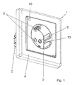
- Fig. 1
- eine perspektivische Ansicht einer elektrischen Steckdose,
- Fig. 2
- eine perspektivische Ansicht einer weiteren elektrischen Steckdose,
- Fig. 3
- eine Schnittdarstellung einer Steckdose mit Lösemitteln in einer eingezogenen Position,
- Fig. 4
- eine Schnittdarstellung einer Steckdose mit Lösemitteln in einer ausgefahrenen Position, und
- Fig. 5
- eine Schnittdarstellung eines weiteren Ausführungsbeispiels einer elektrischen Steckdose.
- Gleiche oder gleichwirkende Bauteile sind in der nachfolgenden Beschreibung mit gleichen Bezugszeichen versehen.
- Nachfolgend wird der Aufbau und die Funktionsweise der erfindungsgemäßen Steckdose 1 schematisch anhand von alternativen Ausführungsbeispielen näher beschrieben.
- Die Steckdose 1 kann in einem nicht dargestellten Installationsgehäuse befestigt werden, welches ortsfest in einer Gebäudewand fixiert ist. Die Steckdose 1 weist einen Gerätesockel 2 auf, den außenseitig ein Tragrahmen 3 umgibt, der die Befestigung der Steckdose 1 in dem Installationsgehäuse ermöglicht. Frontseitig ist ein mehrteiliges Frontelement 4 angeordnet. Das Frontelement 4 umfasst einen topfförmigen Zentraleinsatz 5 mit Kontaktöffnungen 6 zur Aufnahme von Steckerstiften eines nicht dargestellten Steckers. In dem Gerätesockel 2 sind Klemmen 7 zum Anschluss von Leitungen einer Spannungsversorgung und damit verbundene metallische Kontaktelemente 8 angeordnet, in die frontseitig die Steckerstifte gesteckt werden können. Des weiteren ist in dem Gerätesockel 2 ein Erdungsbügel 9 angeordnet, der zur frontseitigen Kontaktierung eines Erdungskontaktes des Steckers dient.
- Um eine Lösefunktion für den Stecker zu realisieren, umfasst die Steckdose 1 einen Motor 10 und einen Lösemechanismus 11, welche je nach Ausführungsform unterschiedlich angeordnet sind. Der Lösemechanismus 11 weist ein Getriebe 12 und Lösemittel 13 auf. In
Fig. 1 sind Lösemittel 13 in Form von Stiften dargestellt, während inFig. 2 Lösemittel 13 als quaderförmige Bestandteile des Zentraleinsatzes 5 ausgebildet sind. Die Lösemittel 13 sind in der Nähe der Kontaktöffnungen 6 angeordnet, um den Zentraleinsatz 5 sowohl bei zweipoligen als auch bei dreipoligen Steckern verwenden zu können. Die Lösemittel 13 sind beiderseits der Kontaktöffnungen 6 verschiebbar geführt und symmetrisch zueinander in dem Zentraleinsatz 5 angeordnet, um beim Lösen des Steckers ein Verkanten zu vermeiden. Des weiteren sind die Lösemittel 13 beiderseits mit nicht dargestellten Endanschlägen versehen, so dass sie unverlierbar in dem Zentraleinsatz 5 angeordnet sind. - Unterhalb des Zentraleinsatzes 5 befindet sich eine Antriebseinheit 14, die in einem Aufnahmeraum 15 des Gerätesockels 2 angeordnet ist. Die Antriebseinheit 14 umfasst den Motor 10, das Getriebe 12 des Lösemechanismus 11 und elektrische Bauelemente zur Spannungsversorgung und eine Steuerelektronik 16 zur Ansteuerung des Motors 10. Das Getriebe 12 schafft die mechanische Verbindung zu den Lösemitteln 13 in dem Zentraleinsatz 5. Bodenseitig sind Anschlusskontakte 17 berührungsgeschützt aus der Antriebseinheit 14 geführt, die mit den Klemmen 7 und/oder Kontaktelementen 8 in dem Gerätesockel 2 elektrisch kontaktierbar sind und die elektrische Versorgung des Motors 10 gewährleisten. Des weiteren ist an dem Zentraleinsatz 5 ein Befehlsgeber 18 in Form eines Schalters angeordnet, um den Motor 10 einschalten zu können. Die Anschlussleitungen 19 verlaufen entlang des Zentraleinsatzes 5 und sind mittels einer Steckverbindung 20 in die Antriebseinheit 14 geführt.
- Der Motor 10 weist abtriebsseitig ein Zahnrad 21 auf, das die rotatorische Bewegung an ein Getriebe 12 übergibt. Das Getriebe 12 umfasst eine in der Antriebseinheit 14 geführte Zahnstange 22 und einen in der Antriebseinheit 14 gelagerten Hebel 23. Der Hebel 23 ist aus der Antriebseinheit 14 geführt und bildet dort eine Gabel 24 aus, die mit den Lösemitteln 13 in dem Zentraleinsatz 5 mechanisch koppelbar ist. Das Zahnrad 21 kämmt mit der Zahnstange 22, die wiederum den Hebel 23 auf- oder abwärts bewegt und somit die Lösemittel 13 axial in dem Zentraleinsatz 5 verschieben kann.
- In einer Ausführungsform gemäß der
Fig. 5 ist ein Teil des Lösemechanismus 11 zu einer Baugruppe 25 zusammengefasst, die modular bodenseitig an dem Zentraleinsatz 5 angeordnet ist. Die Baugruppe 25 ist vorzugsweise flach ausgeführt und rastend an dem Zentraleinsatz 5 fixiert. In der Baugruppe 25 ist ein Hebel 23 gelagert, der einseitig ausgeführt ist und dort eine Gabel 24 ausbildet, die mit den Lösemitteln 13 in dem Zentraleinsatz 5 mechanisch gekoppelt ist. Eine am Gerätesockel 2 angeordnete Antriebseinheit 14 weist einen Motor 10 auf, dessen rotatorische Bewegung über ein Zahnrad 21 und eine aus der Antriebseinheit 14 ausgeführte Zahnstange 22 auf den Hebel 23 in der Baugruppe 25 übertragen wird. Die Zahnstange 22 und der Hebel 23 sind mechanisch miteinander gekoppelt. - In beiden Ausführungsformen erfolgt eine Aktivierung des Motors 10 über den frontseitig angeordneten Befehlsgeber 18 oder alternativ über einen nicht näher dargestellten in der Steuerelektronik 16 der Antriebseinheit 14 integrierten und drahtlos mittels einer Fernbedienung betätigbaren Funkbausteins. Beide Befehlsgeber 18 geben die Spannungsversorgung für den Motor 10 frei, sodass dessen rotatorische Bewegung über das Getriebe 12 auf die Lösemittel 13 übertragen wird. Die Lösemittel 13 verfahren aus einer eingezogenen Position gemäß
Fig. 3 , in der sich ein Stecker in dem Zentraleinsatz 5 befinden kann, in eine ausgefahrene Position gemäßFig. 4 , in der der Stecker aus dem Zentraleinsatz 5 entgegen einer Steckrichtung X geschoben werden kann, und in einer Entnahmestellung in dem Zentraleinsatz 5 verbleiben kann. Die Steuerelektronik 16 in der Antriebseinheit 14 aktiviert anschließend den Motor 10 zu einer Umkehrbewegung, so dass der mechanisch gekoppelte Lösemechanismus 11 automatisch wieder in die Ursprungsposition gemäßFig. 3 mit eingezogenen Lösemitteln 13 zurückfährt. -
- 1
- Steckdose
- 2
- Gerätesockel
- 3
- Tragrahmen
- 4
- Frontelement
- 5
- Zentraleinsatz
- 6
- Kontaktöffnungen
- 7
- Klemmen
- 8
- Kontaktelemente
- 9
- Erdungsbügel
- 10
- Motor
- 11
- Lösemechanismus
- 12
- Getriebe
- 13
- Lösemittel
- 14
- Antriebseinheit
- 15
- Aufnahmeraum
- 16
- Steuerelektronik
- 17
- Anschlusskontakte
- 18
- Befehlsgeber
- 19
- Anschlussleitungen
- 20
- Steckverbindung
- 21
- Zahnrad
- 22
- Zahnstange
- 23
- Hebel
- 24
- Gabel
- 25
- Baugruppe
- X
- Steckrichtung
Claims (15)
- Steckdose zum Herstellen einer lösbaren Verbindung mit einem Stecker, umfassend einen Gerätesockel (2), einen Lösemechanismus (11), mit welchem ein Stecker entgegen der Steckrichtung (X) aus der Steckdose (1) schiebbar ist, und ein frontseitig befestigtes Frontelement (4), das einen Zentraleinsatz (5) aufweist, wobei im Gerätesockel (2) angeordnete Kontaktelemente (8) an eine Netzspannung anschließbar sind, dadurch gekennzeichnet, dass der Lösemechanismus (11) motorisch antreibbar ist.
- Steckdose nach Patentanspruch 1, dadurch gekennzeichnet, dass ein Motor (10) mechanisch mit dem Lösemechanismus (11) verbunden ist.
- Steckdose nach einem der vorhergehenden Patentansprüche, dadurch gekennzeichnet, dass der Motor (10) an dem Gerätesockel (2) oder an dem Frontelement (4) angeordnet ist.
- Steckdose nach einem der vorhergehenden Patentansprüche, dadurch gekennzeichnet, dass der Motor (10) in einer Antriebseinheit (14) angeordnet ist.
- Steckdose nach Patentanspruch 4, dadurch gekennzeichnet, dass die Antriebseinheit (14) in einem Aufnahmeraum (15) in dem Gerätesockel (2) anordenbar ist.
- Steckdose nach einem der vorhergehenden Patentansprüche, dadurch gekennzeichnet, dass der Lösemechanismus (11) an dem Frontelement (4) und/oder an dem Gerätesockel (2) angeordnet ist.
- Steckdose nach einem der vorhergehenden Patentansprüche, dadurch gekennzeichnet, dass der Lösemechanismus (11) ein Getriebe (12) und mindestens ein Lösemittel (13) umfasst.
- Steckdose nach Patentanspruch 7, dadurch gekennzeichnet, dass das Lösemittel (13) an dem Zentraleinsatz (5) angeordnet ist.
- Steckdose nach einem der Patentansprüche 7 oder 8, dadurch gekennzeichnet, dass das Lösemittel (13) in oder entgegen der Steckrichtung (X) bewegbar ist.
- Steckdose nach einem der vorhergehenden Patentansprüche 7 bis 9, dadurch gekennzeichnet, dass das Lösemittel (13) radial zur Steckrichtung (X) bewegbar ist.
- Steckdose nach einem der vorhergehenden Patentansprüche 7 bis 10, dadurch gekennzeichnet, dass das Lösemittel (13) senkrecht zur Steckrichtung (X) bewegbar ist.
- Steckdose nach einem der vorhergehenden Patentansprüche 7 bis 11, dadurch gekennzeichnet, dass das Lösemittel (13) gleichmäßig entgegen der Steckrichtung (X) auf den Stecker einwirkt.
- Steckdose nach einem der vorhergehenden Patentansprüche 7 bis 12, dadurch gekennzeichnet, dass das Lösemittel (13) in eine Entnahmestellung in der Steckdose bewegbar ist, in der ein endgültiges Lösen des Steckers ohne Kraftaufwand möglich ist.
- Steckdose nach einem der vorhergehenden Patentansprüche 7 bis 13, dadurch gekennzeichnet, dass das Lösemittel (13) automatisch in eine Ausgangslage zurücksetzbar ist.
- Steckdose nach einem der vorhergehenden Patentansprüche, dadurch gekennzeichnet, dass ein Befehlsgeber (18) für den Motor (10) in dem Frontelement (4) angeordnet ist und/oder fern betätigbar ausgeführt ist.
Applications Claiming Priority (1)
| Application Number | Priority Date | Filing Date | Title |
|---|---|---|---|
| DE200810064492 DE102008064492A1 (de) | 2008-12-23 | 2008-12-23 | Steckdose mit Lösemechanismus |
Publications (3)
| Publication Number | Publication Date |
|---|---|
| EP2202851A2 true EP2202851A2 (de) | 2010-06-30 |
| EP2202851A3 EP2202851A3 (de) | 2011-01-26 |
| EP2202851B1 EP2202851B1 (de) | 2016-11-16 |
Family
ID=42026789
Family Applications (1)
| Application Number | Title | Priority Date | Filing Date |
|---|---|---|---|
| EP09015903.9A Not-in-force EP2202851B1 (de) | 2008-12-23 | 2009-12-22 | Steckdose mit Lösemechanismus |
Country Status (2)
| Country | Link |
|---|---|
| EP (1) | EP2202851B1 (de) |
| DE (1) | DE102008064492A1 (de) |
Family Cites Families (8)
| Publication number | Priority date | Publication date | Assignee | Title |
|---|---|---|---|---|
| JPH04155787A (ja) * | 1990-10-19 | 1992-05-28 | Sharp Corp | 引き抜き機構をもつプラグ |
| HU208882B (en) * | 1991-05-03 | 1994-01-28 | Prodax Kft | Receptactle with ejector work for connecting electric consumer |
| US5800189A (en) * | 1996-06-18 | 1998-09-01 | Ahmed; Samir Omar Ramsey | Apparatus and method for automatic disconnector |
| US6062883A (en) * | 1997-08-12 | 2000-05-16 | Schreiber; James W. | Electrical plug ejector with module |
| US6540533B1 (en) * | 1997-08-12 | 2003-04-01 | James W. Schreiber | Remote electrical plug ejector |
| HU225604B1 (en) * | 2001-04-24 | 2007-05-02 | Legrand Magyarorszag Villamoss | Receptacle with picking up apparatus |
| GB2441357A (en) * | 2006-08-29 | 2008-03-05 | Calvin Ka Wing Leung | Electrical connector with ejector |
| DE102007038210B4 (de) * | 2007-07-17 | 2009-11-26 | Enzo Di Turi | Netzanschlussstecker und Staubsauger mit Netzanschlussstecker |
-
2008
- 2008-12-23 DE DE200810064492 patent/DE102008064492A1/de not_active Ceased
-
2009
- 2009-12-22 EP EP09015903.9A patent/EP2202851B1/de not_active Not-in-force
Non-Patent Citations (1)
| Title |
|---|
| None |
Also Published As
| Publication number | Publication date |
|---|---|
| EP2202851A3 (de) | 2011-01-26 |
| EP2202851B1 (de) | 2016-11-16 |
| DE102008064492A1 (de) | 2010-06-24 |
Similar Documents
| Publication | Publication Date | Title |
|---|---|---|
| DE102007063585B4 (de) | Elektrisches Installationsgerät | |
| DE102007038210B4 (de) | Netzanschlussstecker und Staubsauger mit Netzanschlussstecker | |
| EP1670618A1 (de) | Akkuschrauber | |
| DE102009046327A1 (de) | Vorrichtung zur elektrischen Verbindung eines Elektrofahrzeugs mit einer Stromzapfstelle | |
| DE102011055963B4 (de) | Ladedose mit Hebelgetriebe für eine Steckverbindung zur Aufladung eines Elektrofahrzeuges | |
| EP3028349B1 (de) | Endlagenfixierung einer steckverbindung zur erhöhung der vibrationsfestigkeit | |
| EP2368295A1 (de) | Verschlusssystem für eine steckdose | |
| DE4447493C2 (de) | Mehrpolige Steckvorrichtung, insbesondere Rundsteckvorrichtung | |
| EP3273547B1 (de) | Flurförderzeugs mit einer elektrischen steckervorrichtung | |
| DE102009056241A1 (de) | Stützeinrichtung für eine Magnetronanordnung mit einem rotierenden Target | |
| WO2019201676A1 (de) | Steckverbinder | |
| EP2202851B1 (de) | Steckdose mit Lösemechanismus | |
| EP1301380B1 (de) | Wischanlage für eine scheibe eines kraftfahrzeugs | |
| DE102014113461A1 (de) | System für die Kontaktierung einer in einem Fahrzeug befindlichen Batterie mit einem vorzugsweise stationärem Ladegerät | |
| WO2008113634A1 (de) | Verlängerungskabel und daran adaptierte rohrbearbeitungsvorrichtung | |
| EP3471219B1 (de) | Stecksystem und stecker zum herstellen einer elektrischen steckverbindung | |
| EP2648287B1 (de) | Fahrzeugseitige Dose eines Ladesteckverbinders, insbesondere für Flurförderfahrzeuge | |
| CN116316227B (zh) | 一种工业电气配电柜辅助安装设备及工艺 | |
| DE1901074C3 (de) | Elektrisches Schaltgerät oder Relais | |
| EP4142069B1 (de) | Steckdoseneinrichtung für ein fahrzeug | |
| DE102007030088B4 (de) | Antrieb zum Betätigen eines beweglichen Flügels, insbesondere einer Tür oder eines Fensters | |
| WO2024078978A1 (de) | Elektrische verbindung zwischen einer elektrischen einrichtung und einem elektrisch betreibbaren fahrzeug, elektrische einrichtung und elektrisches fahrzeug | |
| EP4637477B1 (de) | Stromversorgungsvorrichtung zur stromversorgung eines ausziehelements | |
| WO2021122808A1 (de) | Linearantrieb mit einfach montierbarem elektromotor | |
| EP1787764B1 (de) | Netzbetriebenes Handwerkzeuggerät |
Legal Events
| Date | Code | Title | Description |
|---|---|---|---|
| PUAI | Public reference made under article 153(3) epc to a published international application that has entered the european phase |
Free format text: ORIGINAL CODE: 0009012 |
|
| AK | Designated contracting states |
Kind code of ref document: A2 Designated state(s): AT BE BG CH CY CZ DE DK EE ES FI FR GB GR HR HU IE IS IT LI LT LU LV MC MK MT NL NO PL PT RO SE SI SK SM TR |
|
| AX | Request for extension of the european patent |
Extension state: AL BA RS |
|
| PUAL | Search report despatched |
Free format text: ORIGINAL CODE: 0009013 |
|
| AK | Designated contracting states |
Kind code of ref document: A3 Designated state(s): AT BE BG CH CY CZ DE DK EE ES FI FR GB GR HR HU IE IS IT LI LT LU LV MC MK MT NL NO PL PT RO SE SI SK SM TR |
|
| AX | Request for extension of the european patent |
Extension state: AL BA RS |
|
| RIC1 | Information provided on ipc code assigned before grant |
Ipc: H01R 13/635 20060101AFI20100325BHEP Ipc: H01R 43/26 20060101ALI20101217BHEP |
|
| 17P | Request for examination filed |
Effective date: 20110726 |
|
| 17Q | First examination report despatched |
Effective date: 20130226 |
|
| GRAP | Despatch of communication of intention to grant a patent |
Free format text: ORIGINAL CODE: EPIDOSNIGR1 |
|
| INTG | Intention to grant announced |
Effective date: 20160527 |
|
| GRAS | Grant fee paid |
Free format text: ORIGINAL CODE: EPIDOSNIGR3 |
|
| GRAA | (expected) grant |
Free format text: ORIGINAL CODE: 0009210 |
|
| AK | Designated contracting states |
Kind code of ref document: B1 Designated state(s): AT BE BG CH CY CZ DE DK EE ES FI FR GB GR HR HU IE IS IT LI LT LU LV MC MK MT NL NO PL PT RO SE SI SK SM TR |
|
| REG | Reference to a national code |
Ref country code: GB Ref legal event code: FG4D Free format text: NOT ENGLISH |
|
| REG | Reference to a national code |
Ref country code: CH Ref legal event code: EP |
|
| REG | Reference to a national code |
Ref country code: IE Ref legal event code: FG4D Free format text: LANGUAGE OF EP DOCUMENT: GERMAN |
|
| REG | Reference to a national code |
Ref country code: AT Ref legal event code: REF Ref document number: 846711 Country of ref document: AT Kind code of ref document: T Effective date: 20161215 |
|
| REG | Reference to a national code |
Ref country code: DE Ref legal event code: R096 Ref document number: 502009013373 Country of ref document: DE |
|
| REG | Reference to a national code |
Ref country code: FR Ref legal event code: PLFP Year of fee payment: 8 |
|
| PG25 | Lapsed in a contracting state [announced via postgrant information from national office to epo] |
Ref country code: LV Free format text: LAPSE BECAUSE OF FAILURE TO SUBMIT A TRANSLATION OF THE DESCRIPTION OR TO PAY THE FEE WITHIN THE PRESCRIBED TIME-LIMIT Effective date: 20161116 |
|
| REG | Reference to a national code |
Ref country code: SE Ref legal event code: TRGR |
|
| REG | Reference to a national code |
Ref country code: NL Ref legal event code: MP Effective date: 20161116 |
|
| REG | Reference to a national code |
Ref country code: LT Ref legal event code: MG4D |
|
| PG25 | Lapsed in a contracting state [announced via postgrant information from national office to epo] |
Ref country code: LT Free format text: LAPSE BECAUSE OF FAILURE TO SUBMIT A TRANSLATION OF THE DESCRIPTION OR TO PAY THE FEE WITHIN THE PRESCRIBED TIME-LIMIT Effective date: 20161116 Ref country code: NL Free format text: LAPSE BECAUSE OF FAILURE TO SUBMIT A TRANSLATION OF THE DESCRIPTION OR TO PAY THE FEE WITHIN THE PRESCRIBED TIME-LIMIT Effective date: 20161116 Ref country code: GR Free format text: LAPSE BECAUSE OF FAILURE TO SUBMIT A TRANSLATION OF THE DESCRIPTION OR TO PAY THE FEE WITHIN THE PRESCRIBED TIME-LIMIT Effective date: 20170217 Ref country code: NO Free format text: LAPSE BECAUSE OF FAILURE TO SUBMIT A TRANSLATION OF THE DESCRIPTION OR TO PAY THE FEE WITHIN THE PRESCRIBED TIME-LIMIT Effective date: 20170216 |
|
| PG25 | Lapsed in a contracting state [announced via postgrant information from national office to epo] |
Ref country code: FI Free format text: LAPSE BECAUSE OF FAILURE TO SUBMIT A TRANSLATION OF THE DESCRIPTION OR TO PAY THE FEE WITHIN THE PRESCRIBED TIME-LIMIT Effective date: 20161116 Ref country code: PT Free format text: LAPSE BECAUSE OF FAILURE TO SUBMIT A TRANSLATION OF THE DESCRIPTION OR TO PAY THE FEE WITHIN THE PRESCRIBED TIME-LIMIT Effective date: 20170316 Ref country code: HR Free format text: LAPSE BECAUSE OF FAILURE TO SUBMIT A TRANSLATION OF THE DESCRIPTION OR TO PAY THE FEE WITHIN THE PRESCRIBED TIME-LIMIT Effective date: 20161116 Ref country code: PL Free format text: LAPSE BECAUSE OF FAILURE TO SUBMIT A TRANSLATION OF THE DESCRIPTION OR TO PAY THE FEE WITHIN THE PRESCRIBED TIME-LIMIT Effective date: 20161116 Ref country code: BE Free format text: LAPSE BECAUSE OF NON-PAYMENT OF DUE FEES Effective date: 20161231 Ref country code: ES Free format text: LAPSE BECAUSE OF FAILURE TO SUBMIT A TRANSLATION OF THE DESCRIPTION OR TO PAY THE FEE WITHIN THE PRESCRIBED TIME-LIMIT Effective date: 20161116 |
|
| PG25 | Lapsed in a contracting state [announced via postgrant information from national office to epo] |
Ref country code: DK Free format text: LAPSE BECAUSE OF FAILURE TO SUBMIT A TRANSLATION OF THE DESCRIPTION OR TO PAY THE FEE WITHIN THE PRESCRIBED TIME-LIMIT Effective date: 20161116 Ref country code: SK Free format text: LAPSE BECAUSE OF FAILURE TO SUBMIT A TRANSLATION OF THE DESCRIPTION OR TO PAY THE FEE WITHIN THE PRESCRIBED TIME-LIMIT Effective date: 20161116 Ref country code: EE Free format text: LAPSE BECAUSE OF FAILURE TO SUBMIT A TRANSLATION OF THE DESCRIPTION OR TO PAY THE FEE WITHIN THE PRESCRIBED TIME-LIMIT Effective date: 20161116 Ref country code: RO Free format text: LAPSE BECAUSE OF FAILURE TO SUBMIT A TRANSLATION OF THE DESCRIPTION OR TO PAY THE FEE WITHIN THE PRESCRIBED TIME-LIMIT Effective date: 20161116 Ref country code: CZ Free format text: LAPSE BECAUSE OF FAILURE TO SUBMIT A TRANSLATION OF THE DESCRIPTION OR TO PAY THE FEE WITHIN THE PRESCRIBED TIME-LIMIT Effective date: 20161116 |
|
| REG | Reference to a national code |
Ref country code: CH Ref legal event code: PL |
|
| REG | Reference to a national code |
Ref country code: DE Ref legal event code: R097 Ref document number: 502009013373 Country of ref document: DE |
|
| PG25 | Lapsed in a contracting state [announced via postgrant information from national office to epo] |
Ref country code: BG Free format text: LAPSE BECAUSE OF FAILURE TO SUBMIT A TRANSLATION OF THE DESCRIPTION OR TO PAY THE FEE WITHIN THE PRESCRIBED TIME-LIMIT Effective date: 20170216 Ref country code: SM Free format text: LAPSE BECAUSE OF FAILURE TO SUBMIT A TRANSLATION OF THE DESCRIPTION OR TO PAY THE FEE WITHIN THE PRESCRIBED TIME-LIMIT Effective date: 20161116 Ref country code: IT Free format text: LAPSE BECAUSE OF FAILURE TO SUBMIT A TRANSLATION OF THE DESCRIPTION OR TO PAY THE FEE WITHIN THE PRESCRIBED TIME-LIMIT Effective date: 20161116 |
|
| PLBE | No opposition filed within time limit |
Free format text: ORIGINAL CODE: 0009261 |
|
| STAA | Information on the status of an ep patent application or granted ep patent |
Free format text: STATUS: NO OPPOSITION FILED WITHIN TIME LIMIT |
|
| PG25 | Lapsed in a contracting state [announced via postgrant information from national office to epo] |
Ref country code: MC Free format text: LAPSE BECAUSE OF FAILURE TO SUBMIT A TRANSLATION OF THE DESCRIPTION OR TO PAY THE FEE WITHIN THE PRESCRIBED TIME-LIMIT Effective date: 20161116 |
|
| REG | Reference to a national code |
Ref country code: IE Ref legal event code: MM4A |
|
| 26N | No opposition filed |
Effective date: 20170817 |
|
| GBPC | Gb: european patent ceased through non-payment of renewal fee |
Effective date: 20170216 |
|
| PG25 | Lapsed in a contracting state [announced via postgrant information from national office to epo] |
Ref country code: LI Free format text: LAPSE BECAUSE OF NON-PAYMENT OF DUE FEES Effective date: 20161231 Ref country code: CH Free format text: LAPSE BECAUSE OF NON-PAYMENT OF DUE FEES Effective date: 20161231 Ref country code: LU Free format text: LAPSE BECAUSE OF NON-PAYMENT OF DUE FEES Effective date: 20161222 |
|
| REG | Reference to a national code |
Ref country code: FR Ref legal event code: PLFP Year of fee payment: 9 |
|
| PG25 | Lapsed in a contracting state [announced via postgrant information from national office to epo] |
Ref country code: IE Free format text: LAPSE BECAUSE OF NON-PAYMENT OF DUE FEES Effective date: 20161222 Ref country code: SI Free format text: LAPSE BECAUSE OF FAILURE TO SUBMIT A TRANSLATION OF THE DESCRIPTION OR TO PAY THE FEE WITHIN THE PRESCRIBED TIME-LIMIT Effective date: 20161116 |
|
| REG | Reference to a national code |
Ref country code: BE Ref legal event code: MM Effective date: 20161231 |
|
| REG | Reference to a national code |
Ref country code: AT Ref legal event code: MM01 Ref document number: 846711 Country of ref document: AT Kind code of ref document: T Effective date: 20161222 |
|
| PG25 | Lapsed in a contracting state [announced via postgrant information from national office to epo] |
Ref country code: GB Free format text: LAPSE BECAUSE OF NON-PAYMENT OF DUE FEES Effective date: 20170216 |
|
| PG25 | Lapsed in a contracting state [announced via postgrant information from national office to epo] |
Ref country code: AT Free format text: LAPSE BECAUSE OF NON-PAYMENT OF DUE FEES Effective date: 20161222 Ref country code: CY Free format text: LAPSE BECAUSE OF FAILURE TO SUBMIT A TRANSLATION OF THE DESCRIPTION OR TO PAY THE FEE WITHIN THE PRESCRIBED TIME-LIMIT Effective date: 20161116 Ref country code: HU Free format text: LAPSE BECAUSE OF FAILURE TO SUBMIT A TRANSLATION OF THE DESCRIPTION OR TO PAY THE FEE WITHIN THE PRESCRIBED TIME-LIMIT; INVALID AB INITIO Effective date: 20091222 |
|
| PG25 | Lapsed in a contracting state [announced via postgrant information from national office to epo] |
Ref country code: MK Free format text: LAPSE BECAUSE OF FAILURE TO SUBMIT A TRANSLATION OF THE DESCRIPTION OR TO PAY THE FEE WITHIN THE PRESCRIBED TIME-LIMIT Effective date: 20161116 Ref country code: IS Free format text: LAPSE BECAUSE OF FAILURE TO SUBMIT A TRANSLATION OF THE DESCRIPTION OR TO PAY THE FEE WITHIN THE PRESCRIBED TIME-LIMIT Effective date: 20161116 Ref country code: TR Free format text: LAPSE BECAUSE OF FAILURE TO SUBMIT A TRANSLATION OF THE DESCRIPTION OR TO PAY THE FEE WITHIN THE PRESCRIBED TIME-LIMIT Effective date: 20161116 |
|
| PG25 | Lapsed in a contracting state [announced via postgrant information from national office to epo] |
Ref country code: MT Free format text: LAPSE BECAUSE OF FAILURE TO SUBMIT A TRANSLATION OF THE DESCRIPTION OR TO PAY THE FEE WITHIN THE PRESCRIBED TIME-LIMIT Effective date: 20161116 |
|
| PGFP | Annual fee paid to national office [announced via postgrant information from national office to epo] |
Ref country code: SE Payment date: 20231110 Year of fee payment: 15 Ref country code: FR Payment date: 20231108 Year of fee payment: 15 Ref country code: DE Payment date: 20231031 Year of fee payment: 15 |
|
| REG | Reference to a national code |
Ref country code: DE Ref legal event code: R119 Ref document number: 502009013373 Country of ref document: DE |
|
| REG | Reference to a national code |
Ref country code: SE Ref legal event code: EUG |
|
| PG25 | Lapsed in a contracting state [announced via postgrant information from national office to epo] |
Ref country code: DE Free format text: LAPSE BECAUSE OF NON-PAYMENT OF DUE FEES Effective date: 20250701 |
|
| PG25 | Lapsed in a contracting state [announced via postgrant information from national office to epo] |
Ref country code: FR Free format text: LAPSE BECAUSE OF NON-PAYMENT OF DUE FEES Effective date: 20241231 |