EP2201658B1 - Automatisches ladungsausgleichsverfahren und gerät für in serie geschaltete batteriereihe - Google Patents
Automatisches ladungsausgleichsverfahren und gerät für in serie geschaltete batteriereihe Download PDFInfo
- Publication number
- EP2201658B1 EP2201658B1 EP08839497.8A EP08839497A EP2201658B1 EP 2201658 B1 EP2201658 B1 EP 2201658B1 EP 08839497 A EP08839497 A EP 08839497A EP 2201658 B1 EP2201658 B1 EP 2201658B1
- Authority
- EP
- European Patent Office
- Prior art keywords
- battery
- battery cell
- potential
- string
- charge
- Prior art date
- Legal status (The legal status is an assumption and is not a legal conclusion. Google has not performed a legal analysis and makes no representation as to the accuracy of the status listed.)
- Active
Links
Images


Classifications
-
- H02J7/54—
-
- H—ELECTRICITY
- H01—ELECTRIC ELEMENTS
- H01M—PROCESSES OR MEANS, e.g. BATTERIES, FOR THE DIRECT CONVERSION OF CHEMICAL ENERGY INTO ELECTRICAL ENERGY
- H01M10/00—Secondary cells; Manufacture thereof
- H01M10/42—Methods or arrangements for servicing or maintenance of secondary cells or secondary half-cells
- H01M10/44—Methods for charging or discharging
- H01M10/441—Methods for charging or discharging for several batteries or cells simultaneously or sequentially
-
- H02J7/575—
-
- H02J7/80—
-
- Y—GENERAL TAGGING OF NEW TECHNOLOGICAL DEVELOPMENTS; GENERAL TAGGING OF CROSS-SECTIONAL TECHNOLOGIES SPANNING OVER SEVERAL SECTIONS OF THE IPC; TECHNICAL SUBJECTS COVERED BY FORMER USPC CROSS-REFERENCE ART COLLECTIONS [XRACs] AND DIGESTS
- Y02—TECHNOLOGIES OR APPLICATIONS FOR MITIGATION OR ADAPTATION AGAINST CLIMATE CHANGE
- Y02E—REDUCTION OF GREENHOUSE GAS [GHG] EMISSIONS, RELATED TO ENERGY GENERATION, TRANSMISSION OR DISTRIBUTION
- Y02E60/00—Enabling technologies; Technologies with a potential or indirect contribution to GHG emissions mitigation
- Y02E60/10—Energy storage using batteries
-
- Y—GENERAL TAGGING OF NEW TECHNOLOGICAL DEVELOPMENTS; GENERAL TAGGING OF CROSS-SECTIONAL TECHNOLOGIES SPANNING OVER SEVERAL SECTIONS OF THE IPC; TECHNICAL SUBJECTS COVERED BY FORMER USPC CROSS-REFERENCE ART COLLECTIONS [XRACs] AND DIGESTS
- Y02—TECHNOLOGIES OR APPLICATIONS FOR MITIGATION OR ADAPTATION AGAINST CLIMATE CHANGE
- Y02T—CLIMATE CHANGE MITIGATION TECHNOLOGIES RELATED TO TRANSPORTATION
- Y02T10/00—Road transport of goods or passengers
- Y02T10/60—Other road transportation technologies with climate change mitigation effect
- Y02T10/70—Energy storage systems for electromobility, e.g. batteries
Definitions
- the present invention relates to an automatic charge equalization method and apparatus, more particularly, to an automatic charge equalization apparatus and method having an automatic PWM generating means for a series-connected battery string.
- unit battery In a case that a potential higher than a basic potential of unit battery (cell) is necessary, such as a hybrid vehicle using a lithium ion cell as a power source, it is common to use a plurality of unit batteries which is connected in series. However, even though the batteries are produced with the same structure via a typical production method using the same anode, cathode and electrolyte material, a difference in charging or discharging (and self discharging) characteristics exists between each of the batteries connected in series.
- Korean patent Laid-Open No. 2007-0031406 is directed to an apparatus and method for equalizing the charges of series-connected individual cells of an energy storage using a DC/DC converter to which the energy is supplied from the energy storage or other energy source, and more specifically, the DC/DC converter charges an intermediate circuit capacitor, and a voltage of the intermediate circuit capacitor is reversed by the DC/AC converter so that the alternating voltage is converted to a pulsed direct current by a rectifier through AC bus lines and combined transformer and the cell having lowest voltage is charged with the pulsed direct current.
- Korean Patent Laid-Open 2007-0006762 is directed to an apparatus for equalizing charge of series-connected capacitors of 2-step capacitor (DLC) in which individual transformers Tr1 to Trn assigned to each of capacitors C1 to Cn respectively and a voltage comparator are provided and a secondary winding of the individual transformer is connected via the individual diodes D1 to Dn to an anode terminal of the capacitor and directly connected to a cathode terminal of the capacitor.
- DLC 2-step capacitor
- European Patent Registration No. EP 0432639 is directed to a charge equalizing apparatus which equalizes charge between low-charged battery and the remaining batteries if a plurality of batteries is connected in series by providing charging circuit including a rectangular-functional generator and a comparing circuit and diode, transformer and contact breaker, for each individual battery of a battery stack.
- U.S. Patent Registration No. US 5659237 is directed to a charge equalizing apparatus which equalizes charge of at least 2 series-connected energy storage cell, comprising a transformer having a primary winding and a secondary winding (herein, the secondary winding is connected to one of an energy storage cells), a forward converter for inducing the charging current in each of the secondary windings by applying the equalizing voltage signal to the primary winding of the transformer, and a means for increasing a magnitude of the voltage signal until the energy storage cells are equalized while charging lower cells.
- WO 2005/112222 A1 discloses a charge equalization apparatus for a series-connected battery string, comprising a battery string consisted of a plurality of batteries connected in series; nth battery cell composing the battery string; an automatic generating means connected in parallel to each of the batteries composing the battery string; and a charge equalizer connected in parallel to each of the batteries composing the battery string.
- a comparator generates an output signal by comparing a potential of the nth battery cell with an average potential of the battery string, and the charge equalizer is automatically controlled to charge or discharge the nth battery cell according to the output signal automatically generated by the comparator.
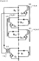
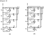
- the prior technology can be represented as Fig. 1 , in which batteries B 1 to B N are connected in series in a center portion and DC/DC converters 110_1 to 110_N are connected to every two adjoining batteries.
- the DC/DC converter is implemented in such a way to discharge the energy from top battery and charge the energy to bottom battery of the two adjoining batteries.
- the DC/DC converter is implemented such that the discharged energy is charged to an uppermost-located battery B N of the series-connected battery string.
- the charge equalizing apparatus in Fig. 1 allows the charge equalization to be accomplished by moving charge from the top cell to the bottom cell of two adjoining cells when the charge imbalance is caused.
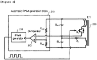
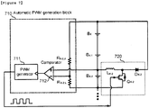
- Fig. 2 shows an example of the charge equalizing apparatus having an automatic PWM generating means 210 for the nth cell.
- a forward converter 220 is provided between two batteries B N+1 , B n connected in series, and an input of the forward converter is connected to the top cell and an output of the forward converter is connected to the bottom cell respectively.
- An anode terminal and a cathode terminal of a comparator 212 are connected to an average potential of the batteries and a potential of the nth battery B n respectively.
- An output of the comparator 212 is used to drive a PWM generator 211 and the PWM signal generated by the PWM generator 211 is used to drive the forward converter 220.
- the PWM signal is generated when the potential of the top cell B n+1 is higher than that of the bottom cell B n of the two batteries connected in series, and the PWM signal operates the forward converter 220 and as a result, the charge equalization is accomplished in such a way that the charge is moved from the over-charged top cell to relatively low-charged bottom cell.
- the charge equalization is accomplished in such a way that the charge is moved from the over-charged battery to relatively low-charged battery by comparing potentials of the two adjoining batteries.
- the automatic charge equalizing apparatus determines the potential of two adjoining batteries and initiates the charge equalization operation if the potential of the top battery is higher than that of the bottom battery. Therefore, the prior technology has limitations in that the charge is discharged from the cell having a low potential if two cells having relatively low potential of the series-connected battery string are adjoining. In other words, even though some adjoining cells are low-charged at the same time, since the charge equalizing apparatus is operated by determining the potential between the two adjoining cells, the energy can be discharged from the relatively low-charged battery cell.
- the charge equalizing apparatus can be structured such that the energy is discharged only if the potential of the current cell is higher by comparing the average potential of total battery cells and the average potential of the current cell of interest, which results from complexity of the charge equalizing apparatus.
- An object of the present invention is to provide a charge equalization apparatus and method for a series-connected battery string which allow the energy not to be discharged from relatively low-charged battery cell by comparing it with an average potential of total batteries. Further, other object of the present invention is to provide a charge equalization apparatus and method for series-connected battery string which can overcome a complexity of a charge equalization apparatus when the charge equalization apparatus is designed to be operated by comparing an average potential of total batteries with potential of a current battery cell of interest.
- a charge equalization apparatus for a series-connected battery string as defined in independent claim 1 and a charge equalization method for a charge equalization apparatus for a series-connected battery string as defined in independent claim 10 are provided.
- the dependent claims define preferred and/or advantageous embodiments of the invention.
- the charge equalization method and apparatus can accomplish charge equalization by comparing a potential of a corresponding battery cell with an average potential of a plurality of battery cells including the corresponding battery cell when charging or discharging the charge to/from the corresponding battery cell.
- the present invention can address prior problems in that the charge can be flowed in or flowed out from the corresponding battery cell if the battery is relatively lower or higher compared with the adjoining battery cells even if some adjoining battery cells are low-charged or over-charged.
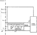
- Fig. 3 is a diagram showing a general structure of a charge equalization apparatus having an automatic PWM generating means 310 according to one embodiment of the present invention.
- a battery string of m 330 having m batteries connected in series on the leftmost side.
- the battery string of m 330 is one portion of the series-connected battery string.
- a battery located at the undermost of the battery string of m is a current battery B n .
- the nth battery cell means a battery cell in which the charge equalization induced by charging and discharging is accomplished, among any batteries composing the battery string of m 330.
- the battery cell Bn+(m-1) in the order of the same number as the number of the batteries composing the battery string of m 330 is called as the (n+(m-1))th battery.
- the battery string of m 330 is connected in parallel to an automatic PWM generating means 310.
- the automatic PWM generating means 310 includes a PWM generator 311 and a comparator 312 for controlling the PWM generator 311.
- the charge equalizer 320 capable of charging or discharging the nth battery cell of current battery string is controlled according to the PWM signal automatically generated by the PWM generator 311 to start or stop charging or discharging operation.
- the charge equalizer 320 preferably comprises a DC/DC converter. Referring to Fig.
- the main features of the automatic charge equalization apparatus is that the DC/DC converter is controlled to be operated by the PWM signal generated at the PWM generator to cause the nth battery cell to be charged or discharged so that the charge equalization of the nth battery cell is accomplished, by comparing a potential of the nth battery cell with an average potential of m (m is at least 3 and up to the number of total batteries composing the battery string) battery cells including the nth battery cell and generating the PWM signal automatically at the PWM generator by an output of the comparator.
- m is at least 3 and up to the number of total batteries composing the battery string
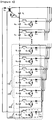
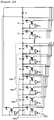
- Fig. 4 is a diagram showing a discharge-type automatic charge equalization apparatus according to one embodiment of the present invention.
- the apparatus 401 capable of discharging the charge is connected in parallel to each battery cell of the battery string B 1 to B k having total k batteries connected in series.
- the energy discharged from the (k-2)th battery cell B k-2 is charged into the (k-1)th battery cell B k-1 and the kth battery cell B k and the energy discharged from the (k-1)th battery cell B k-1 is charged into the kth battery cell B k .
- the energy discharged from the kth battery cell B k is charged into a battery cell B 1 located undermost of batteries connected in series.
- Fig. 5 shows charge equalizing procedures of the first battery cell B 1 in the automatic charge equalization apparatus according to one embodiment of the present invention based on Fig. 4 . If a switch Q 1 is turned on, the energy discharged from the first battery cell B 1 is stored in an inductor L 1 . Thereafter, if the switch Q 1 is turned off, the stored energy is entered into a second, third and fourth battery B 2 , B 3 and B 4 connected in series via a diode D 1 (a dotted line arrow of Fig. 5 express a movement of charge according to operational states of the switch).
- Fig. 6 is a diagram showing a discharge-type charge equalization apparatus having an automatic PWM generating means using a localized average potential according to one embodiment of the present invention.
- the localized total potential means a total potential of the battery string of m
- the localized average potential means an average potential of m batteries composing the battery string of m.
- a method of operating the charge equalization apparatus is proposed if a potential of the current battery cell B 1 is higher than an average potential of m battery cells by comparing the battery cell B 1 of interest with the localized average potential of up to upper (m-1)th battery cell B 4 based on the current battery cell B 1 including the current battery cell B 1 .
- An anode and a cathode of the comparator 612 within the automatic PWM generating means is connected to the potential of the first battery cell B 1 and the average potential of the first battery cell B 1 to the fourth battery cell B 4 respectively.
- the output of the comparator 612 is connected to the PWM generator 611 so that the PWM generator 611 generates a PWM signal if the output of comparator 612 is high.
- the PWM signal has a fixed duty ratio to control operation of the charge equalizer 620 comprising a discharge-type DC/DC converter 621, a switch Q 1 622 for driving the discharge-type DC/DC converter and a diode D 1 623 for controlling flowing direction of current.
- the charge equalizer 620 shown in Fig.
- the switch Q 1 622 becomes on by the PWM signal so that the charge equalizer 620 is operated, and subsequently the energy discharged from the first battery cell B 1 is charged into the second battery cell B 2 , the third battery cell B 3 and the fourth battery cell B 4 in series. Such charge equalization operation continues until the potential of the first battery cell B 1 is lower than the localized average potential of upto the fourth battery cell B 4 including itself.
- Fig. 7 is a diagram showing a discharge-type charge equalization apparatus having an automatic PWM generating means 710 for the (k-2)th battery according to one embodiment of the present invention based on Fig. 4 .
- the automatic charge equalization apparatus for the battery string of m where total number of batteries is k and m equals 4 the number of the batteries to be charged with the energy discharged from the (k-2)th battery cell B k-2 is 2 at maximum.
- the batteries capable of being charged are the (k-1)th battery cell B k-1 and the kth battery cell B k .
- a PWM signal is generated by the automatic PWM generating means 710.
- the generated PWM signal is input to the switch Q k-2 to drive the charge equalizer 720 and, as a result, the energy discharged from the (k-2)th battery cell B k-2 is charged into two battery cells B k-1 and B k .
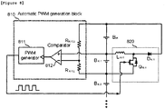
- Fig. 8 is a diagram showing a discharge-type charge equalization apparatus having an automatic PWM generating means 810 for the (k-1)th battery according to one embodiment of the present invention based on Fig. 4 .
- the automatic charge equalization apparatus for the battery string of m where total number of batteries is k and m equals 4 the battery into which the energy discharged from the (k-1)th battery cell B k-1 is entered is only kth battery cell B k .
- a PWM signal is generated by the automatic PWM generating means 810.
- the generated PWM signal is input to the switch Q k-1 to drive the charge equalizer 820 and, as a result, the energy discharged from the (k-1)th battery cell B k-1 is charged into the battery cell B k .
- Fig. 9 is a diagram showing a discharge-type charge equalization apparatus having an automatic PWM generating means 910 for kth battery according to one embodiment of the present invention based on Fig. 4 .
- the automatic PWM generating means 910 is operated to generate the PWM signal.
- the generated PWM signal is input to the switch Q k to drive the charge equalizer 920, and, as a result, the energy discharged from the kth battery cell B k is charged into the first battery cell B 1 .
- Fig. 10 is a diagram showing a charge-type charge equalization apparatus according to another embodiment of the present invention.
- the charge equalization apparatus has k batteries B 1 to B k connected in series in a central portion, and the charge-type charge equalizer 1001 capable of charging the energy into the corresponding battery cell connected in parallel to all battery cells.
- m 1010, 1020, 1030 1040 of k batteries B 1 to B k connected in series where m 4.
- battery cells of the first battery cell B 1 to the (k-3)th battery cell B k-3 in k batteries connected in series can be implemented as a general form of the present invention. But, in a case of the (k-2)th battery cell B k-2 , the (k-1)th battery cell B k-1 and the kth battery cell B k are discharged to charge the (k-2)th battery cell, and only the kth battery cell B k is discharged to charge the (k-1)th battery cell B k-1 . The first battery cell B 1 located in the undermost is discharged to charge the kth battery cell B k located in the uppermost. In Fig.
- a simple flyback converter is used as the charge-type charge equalization apparatus for charging the corresponding battery cell if the battery cell of interest is low-charged.
- DC/DC converter of another type can be used for the same purpose.
- Fig. 11 is a diagram showing charge equalization procedure of the first battery cell B 1 in the automatic charge equalization apparatus according to another embodiment of the present invention based on Fig. 10 .
- the charge-type charge equalizer comprises a transformer, a diode and a switching element (FET, BJT).
- the first battery B 1 in Fig. 11 is connected in parallel to the transformer T 1 having a secondary winding connected in series to the diode.
- a primary winding of the transformer T1 is connected in series to the switch Q 1 and thus connected in parallel to a localized total potential of the battery string of m, i.e., an anode of the fourth battery cell B 4 and a cathode of the first battery cell B 1 .
- the switch Q 1 is turned on by the PWM driving signal generated by the automatic PWM generating means (not shown), the energy is stored in a magnetizing inductor of the transformer T 1 . If the switch Q 1 is turned off, the energy stored at the magnetizing inductor is entered into the first battery cell B 1 via the diode D1.
- the automatic PWM generating means 1210 is provided on left side of the battery and comprises a comparator 1212 and a PWM generator 1211.
- each of two input sides (cathode and anode terminals) of the comparator 1212 is equipped with resistors R 1,U and R 1,L respectively, so that the localized average potential of the battery string of m is compared with a potential of the single battery cell.
- the PWM generating means 1210 generates a PWM signal having a fixed duty ratio, and the PWM signal is input to the switch Q 1 for driving the charge equalizer 1220.
- the energy flowed out from 4 battery cells B 1 to B 4 connected in series is entered into the first battery cell B1.
- Fig. 13 is a diagram showing a charge-type charge equalization apparatus 1320 along with an automatic PWM generating means 1310 for the (k-2)th battery cell B k-2 according to other embodiment of the present invention based on Fig. 10 .
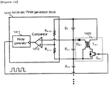
- Fig. 14 is a diagram showing a charge-type charge equalizer 1420 along with an automatic PWM generating means 1410 for the (k-1)th battery cell B k-1 according to other embodiment of the present invention based on Fig. 10 .
- the potential of the (k-1)th battery cell B k-1 is lower than the potential of kth battery cell B k
- the automatic PWM generating means 1410 is operated to generate a PWM signal.
- the generated PWM signal is input to the switch Q k-1 to drive the charge equalizer 1420.
- the energy discharged from two battery cells B k-1 , B k connected in series is charged only by the (k-1)th battery cell B k .
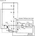
- Fig. 15 is a diagram showing a charge-type charge equalization apparatus 1520 along with an automatic PWM generating means 1510 for kth battery according to other embodiment of the present invention based on Fig. 10 .
- the total battery string has k batteries B 1 to B k connected in series, and the first battery cell B 1 is located in the undermost and the kth battery cell B k is located in the uppermost.
- the flyback converter is implemented for charge equalization of kth battery cell B k , and an input of the flyback converter is connected to the first battery cell B 1 and an output of the flyback converter is connected to the kth battery cell B k .
- the potential of the first battery cell B 1 is connected to an anode terminal and the total potential of the battery string composed of k batteries is connected to a cathode terminal of the comparator 1512 within the automatic PWM generating means 1510.
- two input side (anode terminal and cathode terminal) of the comparator 1512 are equipped with the resistor R k,U , R k,L to compare the average potential of total battery string and the potential of the individual battery cell.
- the PWM signal is generated by the automatic PWM generating means 1510 if the potential of the first battery cell B 1 is higher than that of the total k batteries.
- the generated PWM signal is input to the switch Q k to operate the flyback converter T k .
- the energy of over-charged first battery is entered into total battery string due to operation of the flyback converter.
- a automatic charge equalization method for a charge equalization apparatus for a series-connected battery string comprising a battery string consisted of a plurality of batteries connected in series; an automatic PWM generating means including a comparator connected in parallel to each of the batteries composing the battery string; and a charge equalizer including a DC/DC converter connected in parallel to each of the batteries composing the battery string, comprises steps of:
- the operation of the DC/DC converter is controlled to be started and stopped according to the PWM signal in the step (b) and the PWM signal is automatically generated by an output of the comparator, so that the operation of the DC/DC converter is stopped if the potential of the nth battery cell is similar to the average potential of the battery string of m(localized average potentials).
- the nth battery cell is carried out to be charged and discharged by operating a charge-type DC/DC converter or a discharge-type DC/DC converter, and an input or an output of the DC/DC converter is connected to the battery string of m, so that charging current of the nth battery cell is caused by total potential of the battery string of m and discharging current of the nth battery cell serves as total potential of the battery string of m.
- two inputs of the comparator are a potential of the nth battery cell and an average potential of the batteries composing the battery string of m respectively, and the average potential of the battery string of m is compared with the potential of the nth battery cell using resistors connected to the two inputs respectively.
- the charge equalization method according to the present invention is characterized in that the nth battery cell can generate a plurality of localized average potentials and contribute total potential of the battery string, since the nth battery cell belongs to a plurality of battery strings of m and the comparator within the automatic PWM generating means connected in parallel to the battery cell located in an end portion of the batteries composing the battery string compares the total potential of the battery string with the potential of the battery cell located in an end portion.
Landscapes
- Engineering & Computer Science (AREA)
- Manufacturing & Machinery (AREA)
- Chemical & Material Sciences (AREA)
- Chemical Kinetics & Catalysis (AREA)
- Electrochemistry (AREA)
- General Chemical & Material Sciences (AREA)
- Charge And Discharge Circuits For Batteries Or The Like (AREA)
- Secondary Cells (AREA)
- Battery Mounting, Suspending (AREA)
Claims (16)
- Ladungsausgleichsvorrichtung für eine in Reihe geschaltete Batteriekette, umfassend:eine Batteriekette bestehend aus einer Mehrzahl von Batteriezellen, welche in Reihe geschaltet sind;eine n-te Batteriezelle (Bn), welche zu der Batteriekette gehört;eine Batteriekette aus m Batteriezellen (330; 410, 420, 430, 440; 1010, 1020, 1030, 1040), welche ein Abschnitt der Batteriekette ist und m in Reihe geschaltete Batteriezellen, umfassend die n-te Batteriezelle (Bn), aufweist, wobei die Vorrichtung ferner umfasstzu jeder der Batteriezellen, welche die Batteriekette bilden, ein parallel geschaltetes automatisches PWM-Erzeugungsmittel (310; 610; 710; 810; 910; 1210; 1310; 1410; 1510); undeine Ladungsausgleichseinrichtung (320; 620; 720; 820; 920; 1220; 1320; 1420; 1520), umfassend zu jeder der Batteriezellen, welche die Batteriekette bilden, einen parallel geschalteten DC/DC-Konverter,wobei das automatische PWM-Erzeugungsmittel (310; 610; 710; 810; 910; 1210; 1310; 1410; 1510) einen Komparator (312, 612; 712; 812; 912, 1212; 1312; 1412, 1512) und einen PWM-Generator (311; 611; 711; 811; 911; 1211; 1311; 1411; 1511) umfasst, welcher aus einer Ausgabe des Komparators (312; 612; 712; 812; 912; 1212; 1312; 1412; 1512) automatisch ein PWM-Signal erzeugt; wobei der Komparator (312; 612; 712; 812; 912; 1212; 1312; 1412; 1512) eine Ausgabe durch Vergleichen eines Potenzials der n-ten Batteriezelle (Bn) mit einem Durchschnittspotenzial der gesamten Batteriekette aus m Batteriezellen (330; 410, 420, 430, 440; 1010, 1020, 1030, 1040), umfassend die n-te Batteriezelle, erzeugt und wobei die Ladungsausgleichseinrichtung (320; 620; 720; 820; 920; 1220; 1320; 1420; 1520) die Ladung oder Entladung der n-ten Batteriezelle (Bn) gemäß dem PWM-Signal, welches durch den PWM-Generator (311; 611; 711; 811; 911; 1211; 1311; 1411; 1511) automatisch erzeugt wird, automatisch steuert, undwobei ein Eingang oder ein Ausgang des DC/DC-Konverters mit der Batteriekette aus m Batteriezellen (330; 410, 420, 430, 440; 1010, 1020, 1030, 1040) verbunden ist, sodass ein Ladestrom der n-ten Batteriezelle (Bn) durch ein Gesamtpotenzial der Batteriekette aus m Batteriezellen (330; 410, 420, 430, 440; 1010, 1020, 1030, 1040) hervorgerufen wird, wenn die n-te Batteriezelle (Bn) geladen wird, und ein Entladestrom der n-ten Batteriezelle (Bn) als ein Gesamtpotenzial der Batteriekette aus m Batteriezellen (330; 410, 420, 430, 440; 1010, 1020, 1030, 1040) dient, wenn die n-te Batteriezelle (Bn) entladen wird,wobei sich die n-te Batteriezelle (Bn) auf jede einzelne Batterie der Mehrzahl von in Reihe geschalteten Batterien bezieht, welche die Batteriekette bilden, und m ist zumindest 3 und hoch bis zu der Gesamtanzahl (k) von Batterien, welche die Batteriekette bilden.
- Ladungsausgleichsvorrichtung gemäß Anspruch 1, wobei zwei Eingänge des Komparators (312; 612; 712; 812; 912; 1212; 1312; 1412; 1512) ein Potenzial der n-ten Batteriezelle (Bn) und ein Durchschnittspotenzial der Batterien sind, welche die Batteriekette aus m Batteriezellen (330; 410, 420, 430, 440; 1010, 1020, 1030, 1040) bilden.
- Ladungsausgleichsvorrichtung gemäß Anspruch 2, wobei die zwei Eingänge des Komparators (312; 612; 712; 812; 912; 1212; 1312; 1412; 1512) jeweils mit einem Widerstand (RK, U; RK, L) versehen sind, welcher das Durchschnittspotenzial der Batteriekette aus m Batteriezellen (330; 410, 420, 430, 440; 1010, 1020, 1030, 1040) mit dem Potenzial der n-ten Batteriezelle (Bn) vergleicht.
- Ladungsausgleichsvorrichtung gemäß Anspruch 1, wobei der DC/DC-Konverter ein Ladungstyp-Konverter (1001) ist und ein Gesamtpotenzial der Batteriekette aus m Batteriezellen (330; 410, 420, 430, 440; 1010, 1020, 1030, 1040) als eine Eingabe hat.
- Ladungsausgleichsvorrichtung gemäß Anspruch 1, wobei das automatische PWM-Erzeugungsmittel (310; 610; 710; 810; 910; 1210; 1310; 1410; 1510) das PWM-Signal erzeugt, wenn das Potenzial der n-ten Batteriezelle (Bn) niedriger ist als das Durchschnittspotenzial der Batteriekette aus m Batteriezellen (330; 410, 420, 430, 440; 1010, 1020, 1030, 1040).
- Ladungsausgleichsvorrichtung gemäß Anspruch 1, wobei der DC/DC-Konverter ein Entladungstyp-DC/DC-Konverter (410) ist.
- Ladungsausgleichsvorrichtung gemäß Anspruch 6, wobei das automatische PWM-Erzeugungsmittel (310; 610; 710; 810; 910; 1210; 1310; 1410; 1510) das PWM-Signal erzeugt, wenn das Potenzial der n-ten Batteriezelle (Bn) höher ist als das Durchschnittspotenzial der Batteriekette aus m Batteriezellen (330; 410, 420, 430, 440; 1010, 1020, 1030, 1040).
- Ladungsausgleichsvorrichtung gemäß Anspruch 1, wobei die n-te Batteriezelle (Bn) zu einer beliebigen der Batterieketten aus m Batteriezellen (330; 410, 420, 430, 440; 1010, 1020, 1030, 1040) in einem Bereich von zumindest 1 bis hoch zu m gehört.
- Ladungsausgleichsvorrichtung gemäß Anspruch 8, wobei zwei Eingänge eines Komparators (312; 612; 712; 812; 912; 1212; 1312; 1412; 1512), welcher in einer an einem Endabschnitt der Batteriekette angeordneten Batteriezelle bereitgestellt ist, ein Potenzial der Batteriezelle und ein Durchschnittspotenzial der Batteriezellen sind, welche die Batteriekette bilden.
- Ladungsausgleichsverfahren für eine Ladungsausgleichsvorrichtung für eine in Reihe geschaltete Batteriekette, umfassend eine Batteriekette bestehend aus einer Mehrzahl von Batteriezellen, welche in Reihe geschaltet sind; ein automatisches PWM-Erzeugungsmittel (310; 610; 710; 810; 910; 1210; 1310; 1410; 1510) umfassend zu jeder der Batteriezellen, welche die Batteriekette bilden, einen parallel geschalteten Komparator (312; 612; 712; 812; 912; 1212; 1312; 1412; 1512); und eine Ladungsausgleichseinrichtung (320; 620; 720; 820; 920; 1220; 1320; 1420; 1520) umfassend zu jeder der Batteriezellen, welche die Batteriekette bilden, einen parallel geschalteten DC/DC-Konverter, umfassend die Schritte:(a) automatisches Erzeugen eines PWM-Signals durch Vergleichen eines Potenzials der n-ten Batteriezelle (Bn), welche zu der Batteriekette gehört, mit einem Durchschnittspotenzial der gesamten Batteriekette aus m Batteriezellen (330; 410, 420, 430, 440; 1010, 1020, 1030, 1040), welcher ein Abschnitt der Batteriekette ist und m in Reihe geschaltete Batteriezellen, umfassend die n-te Batteriezelle (Bn), aufweist; und(b) automatisches Steuern der Ladungsausgleichseinrichtung (320; 620; 720; 820; 920; 1220; 1320; 1420; 1520) zum Laden oder Entladen der n-ten Batteriezelle (Bn) gemäß dem PWM-Signal, wobei ein Eingang oder ein Ausgang des DC/DC-Konverters mit der Batteriekette aus m Batteriezellen (330; 410, 420, 430, 440; 1010, 1020, 1030, 1040) verbunden ist, sodass ein Ladestrom der n-ten Batteriezelle (Bn) durch ein Gesamtpotenzial der Batteriekette aus m Batteriezellen (330; 410, 420, 430, 440; 1010, 1020, 1030, 1040) hervorgerufen wird, wenn die n-te Batteriezelle (Bn) geladen wird, und ein Entladestrom der n-ten Batteriezelle (Bn) als ein Gesamtpotenzial der Batteriekette aus m Batteriezellen (330; 410, 420, 430, 440; 1010, 1020, 1030, 1040) dient, wenn die n-te Batteriezelle (Bn) entladen wird,wobei sich die n-te Batteriezelle (Bn) auf jede einzelne Batterie der Mehrzahl von in Reihe geschalteten Batterien bezieht, welche die Batteriekette bilden, und m ist zumindest 3 und hoch bis zu der Gesamtanzahl (k) von Batterien, welche die Batteriekette bilden.
- Ladungsausgleichsverfahren gemäß Anspruch 10, wobei der Betrieb des DC/DC-Konverters so gesteuert wird, dass er in dem Schritt (b) gemäß dem PWM-Signal gestartet und gestoppt wird.
- Ladungsausgleichsverfahren gemäß Anspruch 11, wobei die n-te Batteriezelle (Bn) durch Betreiben eines Ladungstyp-DC/DC-Konverters (1001) oder eines Entladungstyp-DC/DC-Konverters (410) geladen oder entladen wird.
- Ladungsausgleichsverfahren gemäß Anspruch 10, wobei das PWM-Signal, welches durch das automatische PWM-Erzeugungsmittel (310; 610; 710; 810; 910; 1210; 1310; 1410; 1510) erzeugt wird, in dem Schritt (a) gemäß einem Ausgang des Komparators (312; 612; 712; 812; 912; 1212; 1312; 1412; 1512) gesteuert wird.
- Ladungsausgleichsverfahren gemäß Anspruch 10, wobei zwei Eingänge des Komparators (312; 612; 712; 812; 912; 1212; 1312; 1412; 1512) ein Potenzial der n-ten Batteriezelle (Bn) beziehungsweise ein Durchschnittspotenzial der Batterien sind, welche die gesamte Batteriekette aus m Batteriezellen (330; 410, 420, 430, 440; 1010, 1020, 1030, 1040) bilden, und das Durchschnittspotenzial der Batteriekette aus m Batteriezellen (330; 410, 420, 430, 440; 1010, 1020, 1030, 1040) und das Potenzial der n-ten Batteriezelle (Bn) jeweils mittels Widerständen (RK, U; RK, L) verglichen werden, welche mit den beiden Eingängen verbunden sind.
- Ladungsausgleichsverfahren gemäß Anspruch 14, wobei das automatische PWM-Erzeugungsmittel (310; 610; 710; 810; 910; 1210; 1310; 1410; 1510) das PWM-Signal erzeugt, wenn in dem Schritt (a) ein Potenzial der n-ten Batteriezelle (Bn) höher ist als ein Durchschnittspotenzial der gesamten Batteriekette aus m Batteriezellen (330; 410, 420, 430, 440; 1010, 1020, 1030, 1040).
- Ladungsausgleichsverfahren gemäß Anspruch 14, wobei das automatische PWM-Erzeugungsmittel (310; 610; 710; 810; 910; 1210; 1310; 1410; 1510) das PWM-Signal erzeugt, wenn in dem Schritt (a) ein Potenzial der n-ten Batteriezelle (Bn) niedriger ist als ein Durchschnittspotenzial der gesamten Batteriekette aus m Batteriezellen (330; 410, 420, 430, 440; 1010, 1020, 1030, 1040).
Applications Claiming Priority (2)
| Application Number | Priority Date | Filing Date | Title |
|---|---|---|---|
| KR1020070103983A KR101220339B1 (ko) | 2007-10-16 | 2007-10-16 | 직렬연결 배터리 스트링을 위한 자동 전하 균일 방법 및장치 |
| PCT/KR2008/006105 WO2009051414A2 (en) | 2007-10-16 | 2008-10-16 | Automatic charge equalization method and apparatus for series connected battery string |
Publications (3)
| Publication Number | Publication Date |
|---|---|
| EP2201658A2 EP2201658A2 (de) | 2010-06-30 |
| EP2201658A4 EP2201658A4 (de) | 2014-11-19 |
| EP2201658B1 true EP2201658B1 (de) | 2017-08-02 |
Family
ID=40567961
Family Applications (1)
| Application Number | Title | Priority Date | Filing Date |
|---|---|---|---|
| EP08839497.8A Active EP2201658B1 (de) | 2007-10-16 | 2008-10-16 | Automatisches ladungsausgleichsverfahren und gerät für in serie geschaltete batteriereihe |
Country Status (6)
| Country | Link |
|---|---|
| US (1) | US8310204B2 (de) |
| EP (1) | EP2201658B1 (de) |
| JP (1) | JP5175937B2 (de) |
| KR (1) | KR101220339B1 (de) |
| CN (1) | CN101828316B (de) |
| WO (1) | WO2009051414A2 (de) |
Families Citing this family (26)
| Publication number | Priority date | Publication date | Assignee | Title |
|---|---|---|---|---|
| EP2312724A1 (de) * | 2009-10-19 | 2011-04-20 | 4ESys NV | System und Verfahren zum Augleichen von Energiespeichervorrichtungen |
| JP5836283B2 (ja) * | 2010-02-05 | 2015-12-24 | コミサリア ア レネルジ アトミクエ オウ エネルジ アルタナティヴ | 電池のための充電均等化システム |
| FR2956260B1 (fr) * | 2010-02-05 | 2012-04-13 | Commissariat Energie Atomique | Systeme d'equilibrage de charge pour batteries |
| DE102010029460A1 (de) * | 2010-05-28 | 2011-12-01 | Siemens Aktiengesellschaft | Symmetriereinrichtung und Symmetrierverfahren |
| CN101976866B (zh) * | 2010-10-17 | 2012-11-14 | 中国船舶重工集团公司第七一二研究所 | 一种能量转移式电池组均衡判断及补充方法 |
| CN102136749B (zh) * | 2011-03-21 | 2013-09-11 | 艾默生网络能源有限公司 | 充电电池的电流均衡控制方法及装置 |
| CN102157972B (zh) * | 2011-05-18 | 2013-12-25 | 上海恒动汽车电池有限公司 | 一种锂离子电池组均衡系统及其均衡方法 |
| DE102011079253A1 (de) * | 2011-07-15 | 2013-01-17 | Osram Ag | Schaltungsanordnung und verfahren zum angleichen des ladezustandes von seriell verschalteten energiespeichern |
| CN103094935B (zh) * | 2011-10-28 | 2016-01-13 | 东莞钜威新能源有限公司 | 一种电池均衡电路及mos管开关电路 |
| CN103094934A (zh) * | 2011-10-28 | 2013-05-08 | 东莞钜威新能源有限公司 | 一种电池均衡电路 |
| DE102012201404A1 (de) * | 2012-02-01 | 2013-08-01 | Robert Bosch Gmbh | Verfahren und Vorrichtung zum Ladungsausgleich der Batteriezellen einer Batterie |
| KR101165593B1 (ko) * | 2012-02-07 | 2012-07-23 | (주)이미지스테크놀로지 | 양방향 디씨-디씨 컨버터를 이용한 배터리 관리 시스템의 셀 밸런싱 회로 장치 |
| CN103259298A (zh) * | 2012-02-17 | 2013-08-21 | 东莞钜威新能源有限公司 | 一种电池均衡电路及mos管开关电路 |
| CN103311963A (zh) * | 2012-03-08 | 2013-09-18 | 烟台鑫能电源科技开发有限公司 | 一种用于串联连接的电池组的能量均衡电路 |
| JP5817678B2 (ja) * | 2012-08-20 | 2015-11-18 | 株式会社豊田自動織機 | セルバランス装置及びセルバランス方法 |
| FR3000626B1 (fr) * | 2013-01-02 | 2015-02-27 | Renault Sa | Systeme comprenant une batterie formee de modules de batterie, et procede de connexion ou de deconnexion d'un module de batterie correspondant |
| CN103532189B (zh) * | 2013-10-12 | 2016-03-09 | 武汉理工大学 | 基于动态均衡点的电池组均衡控制系统及控制方法 |
| CN104753136A (zh) * | 2015-03-27 | 2015-07-01 | 西安后羿半导体科技有限公司 | 一种大容量锂电池均衡充电装置 |
| CN105161773A (zh) * | 2015-09-11 | 2015-12-16 | 大英德创精工设备有限公司 | 一种正负脉冲铅酸电池化成设备 |
| US10862318B2 (en) * | 2016-01-27 | 2020-12-08 | The University Of Toledo | Bilevel equalizer for battery cell charge management |
| CN106300535B (zh) * | 2016-08-31 | 2019-04-02 | 杰华特微电子(杭州)有限公司 | 电池箱均衡电路及电池箱组 |
| KR102587974B1 (ko) * | 2018-08-16 | 2023-10-10 | 주식회사 엘지에너지솔루션 | 복수의 배터리 간의 직렬 연결 순서를 변경하기 위한 장치 및 방법과 상기 장치를 포함하는 배터리팩 |
| US12308673B2 (en) * | 2019-03-21 | 2025-05-20 | Hefei Gotion High-Tech Power Energy Co., Ltd. | Active equalizer circuit, battery management system, and power supply system |
| US11545841B2 (en) * | 2019-11-18 | 2023-01-03 | Semiconductor Components Industries, Llc | Methods and apparatus for autonomous balancing and communication in a battery system |
| KR102346847B1 (ko) | 2020-12-31 | 2022-01-04 | (주)에이피이씨 | 에너지 저장장치 및 에너지 저장장치의 제어 방법 |
| CN113815491B (zh) * | 2021-09-19 | 2022-05-06 | 段晨 | 一种结合太阳能主动均衡和被动式均衡的电池管理系统 |
Family Cites Families (39)
| Publication number | Priority date | Publication date | Assignee | Title |
|---|---|---|---|---|
| DE3940928C1 (de) * | 1989-12-12 | 1991-07-11 | Fraunhofer-Gesellschaft Zur Foerderung Der Angewandten Forschung Ev, 8000 Muenchen, De | |
| US5631534A (en) * | 1995-08-21 | 1997-05-20 | Delco Electronics Corp. | Bidirectional current pump for battery charge balancing |
| US5659237A (en) * | 1995-09-28 | 1997-08-19 | Wisconsin Alumni Research Foundation | Battery charging using a transformer with a single primary winding and plural secondary windings |
| US5710504A (en) * | 1996-05-20 | 1998-01-20 | The Board Of Trustees Of The University Of Illinois | Switched capacitor system for automatic battery equalization |
| JP3922655B2 (ja) | 1996-07-12 | 2007-05-30 | 株式会社東京アールアンドデー | 電源装置の制御システムおよび電源装置の制御方法 |
| US5869950A (en) * | 1997-10-30 | 1999-02-09 | Lockheed Martin Corp. | Method for equalizing the voltage of traction battery modules of a hybrid electric vehicle |
| JP3899700B2 (ja) * | 1998-09-03 | 2007-03-28 | 株式会社デンソー | 組電池の電圧調整装置及び組電池の電圧調整方法 |
| JPH11262188A (ja) * | 1998-03-13 | 1999-09-24 | Denso Corp | 直列組電池のばらつき補正装置及び方法 |
| KR20000057966A (ko) | 1999-02-12 | 2000-09-25 | 오세광 | 충전용 배터리 관리기 및 그 관리기에 의한 충전용 배터리관리 방법 |
| JP4006877B2 (ja) * | 1999-03-30 | 2007-11-14 | 株式会社デンソー | 組電池の電圧調整装置及び組電池の電圧調整方法 |
| US6140800A (en) * | 1999-05-27 | 2000-10-31 | Peterson; William Anders | Autonomous battery equalization circuit |
| US6150795A (en) * | 1999-11-05 | 2000-11-21 | Power Designers, Llc | Modular battery charge equalizers and method of control |
| CN1352480A (zh) * | 2000-11-09 | 2002-06-05 | 江苏海四达集团公司 | 可充蓄电池组输出平衡器 |
| US6642693B2 (en) * | 2000-11-21 | 2003-11-04 | Nagano Japan Radio Co., Ltd. | Voltage equalizing apparatus for battery devices |
| JP4258133B2 (ja) * | 2001-04-25 | 2009-04-30 | 株式会社デンソー | 充電状態制御装置 |
| US6583602B2 (en) * | 2001-05-11 | 2003-06-24 | Denso Corporation | Vehicular power supply apparatus and method of controlling the same |
| CN1181593C (zh) * | 2002-04-04 | 2004-12-22 | 北京航空航天大学 | 基于电池动态电量差异补偿的自动均衡充放电装置 |
| KR100459991B1 (ko) | 2002-04-10 | 2004-12-04 | 오우석 | 충전용 배터리 관리기 |
| KR100451637B1 (ko) | 2002-06-18 | 2004-10-08 | 오세광 | 충전용 배터리 관리기 |
| KR100460893B1 (ko) * | 2002-08-23 | 2004-12-09 | 현대자동차주식회사 | 하이브리드 전기 자동차의 배터리 관리장치 및 방법 |
| AU2003295715A1 (en) * | 2002-11-25 | 2004-06-18 | Tiax Llc | Cell balancing system for equalizing state of charge among series-connected electrical energy storage units |
| JP3979283B2 (ja) | 2002-12-10 | 2007-09-19 | 株式会社デンソー | 電源装置及びその制御方法 |
| JP3672551B2 (ja) | 2002-12-26 | 2005-07-20 | 株式会社エヌ・ティ・ティ・データ・イー・エックス・テクノ | バッテリの放電制御回路、充電制御回路および充放電制御回路 |
| CN2622906Y (zh) * | 2003-04-01 | 2004-06-30 | 北京天成伟业科技有限责任公司 | 电池组均衡充放电节能保护模块 |
| KR20050004544A (ko) | 2003-07-03 | 2005-01-12 | 오세광 | 인공지능 배터리 관리기 |
| JP3832660B2 (ja) * | 2003-10-29 | 2006-10-11 | 株式会社Nttファシリティーズ | 充電装置 |
| DE102004005136B4 (de) * | 2004-02-02 | 2008-05-08 | Siemens Ag | Vorrichtung und Verfahren zum Ladungsausgleich der in Reihe geschalteten Kondensatoren eines Doppelschichtkondensators |
| JP4144009B2 (ja) * | 2004-04-26 | 2008-09-03 | 株式会社ピューズ | 可変電圧型蓄電装置およびハイブリッド型電源装置 |
| WO2005112222A1 (ja) | 2004-05-13 | 2005-11-24 | Ntt Data Ex Techno Corporation | バッテリの放電制御回路、充電制御回路および充放電制御回路 |
| DE102004031216A1 (de) * | 2004-06-28 | 2006-01-19 | Siemens Ag | Vorrichtung und Verfahren zum Ladungsausgleich in Reihe geschalteter Energiespeicher |
| JP4140585B2 (ja) * | 2004-08-27 | 2008-08-27 | Fdk株式会社 | 直列接続した2次電池のバランス補正装置およびその補正方法 |
| KR100666817B1 (ko) | 2005-01-14 | 2007-01-09 | 주식회사 엘지화학 | 배터리의 밸런싱 장치 및 방법 |
| KR100704944B1 (ko) | 2005-01-31 | 2007-04-06 | 주식회사 리버트론 | 전기 자동차용 배터리 관리 시스템 |
| TWM289925U (en) * | 2005-11-09 | 2006-04-21 | Sino American Electronic Co Lt | Smart-type battery charger with equalizer circuit |
| KR100991084B1 (ko) | 2005-12-15 | 2010-10-29 | 주식회사 엘지화학 | 멀티 전지 팩 시스템 및 그 제어방법, 및 이를 이용한 전지팩 |
| KR100727002B1 (ko) | 2006-03-28 | 2007-06-14 | 넥스콘 테크놀러지 주식회사 | 하이브리드 자동차용 리튬 배터리의 발란싱 모듈 |
| KR100860714B1 (ko) * | 2006-03-29 | 2008-09-29 | 주식회사 디에이텍 | 보조 전원 장치 및 그 제어 방법 |
| JP4621635B2 (ja) * | 2006-07-05 | 2011-01-26 | Fdk株式会社 | 直列セルの電圧バランス補正回路 |
| CN100468911C (zh) * | 2006-12-25 | 2009-03-11 | 苏州市三环技贸有限公司 | 串联动力锂电池组充放电自动均衡方法 |
-
2007
- 2007-10-16 KR KR1020070103983A patent/KR101220339B1/ko active Active
-
2008
- 2008-10-16 CN CN200880111805.6A patent/CN101828316B/zh active Active
- 2008-10-16 US US12/738,333 patent/US8310204B2/en active Active
- 2008-10-16 WO PCT/KR2008/006105 patent/WO2009051414A2/en not_active Ceased
- 2008-10-16 EP EP08839497.8A patent/EP2201658B1/de active Active
- 2008-10-16 JP JP2010529866A patent/JP5175937B2/ja active Active
Non-Patent Citations (1)
| Title |
|---|
| None * |
Also Published As
| Publication number | Publication date |
|---|---|
| EP2201658A2 (de) | 2010-06-30 |
| JP5175937B2 (ja) | 2013-04-03 |
| KR20090038607A (ko) | 2009-04-21 |
| KR101220339B1 (ko) | 2013-01-09 |
| WO2009051414A3 (en) | 2009-07-30 |
| CN101828316B (zh) | 2015-02-18 |
| US8310204B2 (en) | 2012-11-13 |
| JP2011501937A (ja) | 2011-01-13 |
| EP2201658A4 (de) | 2014-11-19 |
| CN101828316A (zh) | 2010-09-08 |
| WO2009051414A2 (en) | 2009-04-23 |
| US20100207578A1 (en) | 2010-08-19 |
Similar Documents
| Publication | Publication Date | Title |
|---|---|---|
| EP2201658B1 (de) | Automatisches ladungsausgleichsverfahren und gerät für in serie geschaltete batteriereihe | |
| CN101467328B (zh) | 电荷均衡设备 | |
| CN101606300B (zh) | 均衡充电设备 | |
| EP2384530B1 (de) | Ladungsausgleichsvorrichtung für eine seriell geschaltete batteriereihe mit regulierter spannungsquelle | |
| EP2201659B1 (de) | Zweistufiges ladungsausgleichsverfahren und gerät für in serie geschaltete batteriereihe | |
| US8120322B2 (en) | Charge equalization apparatus | |
| JP5394919B2 (ja) | 多重変圧器の2次巻線を並列に接続した電荷均等化装置 | |
| US8269455B2 (en) | Charge balancing system | |
| Park et al. | Two-stage cell balancing scheme for hybrid electric vehicle Lithium-ion battery strings | |
| KR20130001234A (ko) | 배터리용 충전 균일화 시스템 | |
| KR20160107173A (ko) | 전기화학 에너지 축전지 및 밸런싱 방법 | |
| JP2015154606A (ja) | 蓄電状態調整回路、蓄電状態調整システム、及び電池パック | |
| JP5285322B2 (ja) | 電圧均等化装置並びに充電装置、組蓄電装置、充電システム | |
| Park et al. | Charge equalization with series coupling of multiple primary windings for hybrid electric vehicle li-ion battery system | |
| WO2021130464A1 (en) | Power supply unit | |
| KR20130002912A (ko) | 배터리 충전회로 | |
| KR20140111242A (ko) | 배터리 충전회로 |
Legal Events
| Date | Code | Title | Description |
|---|---|---|---|
| PUAI | Public reference made under article 153(3) epc to a published international application that has entered the european phase |
Free format text: ORIGINAL CODE: 0009012 |
|
| 17P | Request for examination filed |
Effective date: 20100329 |
|
| AK | Designated contracting states |
Kind code of ref document: A2 Designated state(s): AT BE BG CH CY CZ DE DK EE ES FI FR GB GR HR HU IE IS IT LI LT LU LV MC MT NL NO PL PT RO SE SI SK TR |
|
| AX | Request for extension of the european patent |
Extension state: AL BA MK RS |
|
| RIN1 | Information on inventor provided before grant (corrected) |
Inventor name: MOON, GUN WOO Inventor name: LEE, JOONG HUI Inventor name: OH, JEON KEUN Inventor name: JANG, SOO YEUP Inventor name: KIM, CHONG EUN Inventor name: PARK, HONG SUN Inventor name: KIM, CHOL HO |
|
| RAP1 | Party data changed (applicant data changed or rights of an application transferred) |
Owner name: KOREA ADVANCED INSTITUTE OF SCIENCE AND TECHNOLOGY Owner name: SK INNOVATION CO., LTD. |
|
| DAX | Request for extension of the european patent (deleted) | ||
| A4 | Supplementary search report drawn up and despatched |
Effective date: 20141021 |
|
| RIC1 | Information provided on ipc code assigned before grant |
Ipc: H02J 7/02 20060101AFI20141015BHEP Ipc: H02J 7/00 20060101ALI20141015BHEP |
|
| 17Q | First examination report despatched |
Effective date: 20160406 |
|
| GRAP | Despatch of communication of intention to grant a patent |
Free format text: ORIGINAL CODE: EPIDOSNIGR1 |
|
| INTG | Intention to grant announced |
Effective date: 20170411 |
|
| GRAS | Grant fee paid |
Free format text: ORIGINAL CODE: EPIDOSNIGR3 |
|
| GRAA | (expected) grant |
Free format text: ORIGINAL CODE: 0009210 |
|
| AK | Designated contracting states |
Kind code of ref document: B1 Designated state(s): AT BE BG CH CY CZ DE DK EE ES FI FR GB GR HR HU IE IS IT LI LT LU LV MC MT NL NO PL PT RO SE SI SK TR |
|
| REG | Reference to a national code |
Ref country code: GB Ref legal event code: FG4D |
|
| REG | Reference to a national code |
Ref country code: CH Ref legal event code: EP Ref country code: AT Ref legal event code: REF Ref document number: 915459 Country of ref document: AT Kind code of ref document: T Effective date: 20170815 |
|
| REG | Reference to a national code |
Ref country code: IE Ref legal event code: FG4D |
|
| REG | Reference to a national code |
Ref country code: DE Ref legal event code: R096 Ref document number: 602008051429 Country of ref document: DE |
|
| REG | Reference to a national code |
Ref country code: NL Ref legal event code: MP Effective date: 20170802 |
|
| REG | Reference to a national code |
Ref country code: AT Ref legal event code: MK05 Ref document number: 915459 Country of ref document: AT Kind code of ref document: T Effective date: 20170802 |
|
| REG | Reference to a national code |
Ref country code: LT Ref legal event code: MG4D |
|
| PG25 | Lapsed in a contracting state [announced via postgrant information from national office to epo] |
Ref country code: HR Free format text: LAPSE BECAUSE OF FAILURE TO SUBMIT A TRANSLATION OF THE DESCRIPTION OR TO PAY THE FEE WITHIN THE PRESCRIBED TIME-LIMIT Effective date: 20170802 Ref country code: FI Free format text: LAPSE BECAUSE OF FAILURE TO SUBMIT A TRANSLATION OF THE DESCRIPTION OR TO PAY THE FEE WITHIN THE PRESCRIBED TIME-LIMIT Effective date: 20170802 Ref country code: SE Free format text: LAPSE BECAUSE OF FAILURE TO SUBMIT A TRANSLATION OF THE DESCRIPTION OR TO PAY THE FEE WITHIN THE PRESCRIBED TIME-LIMIT Effective date: 20170802 Ref country code: NL Free format text: LAPSE BECAUSE OF FAILURE TO SUBMIT A TRANSLATION OF THE DESCRIPTION OR TO PAY THE FEE WITHIN THE PRESCRIBED TIME-LIMIT Effective date: 20170802 Ref country code: LT Free format text: LAPSE BECAUSE OF FAILURE TO SUBMIT A TRANSLATION OF THE DESCRIPTION OR TO PAY THE FEE WITHIN THE PRESCRIBED TIME-LIMIT Effective date: 20170802 Ref country code: AT Free format text: LAPSE BECAUSE OF FAILURE TO SUBMIT A TRANSLATION OF THE DESCRIPTION OR TO PAY THE FEE WITHIN THE PRESCRIBED TIME-LIMIT Effective date: 20170802 Ref country code: NO Free format text: LAPSE BECAUSE OF FAILURE TO SUBMIT A TRANSLATION OF THE DESCRIPTION OR TO PAY THE FEE WITHIN THE PRESCRIBED TIME-LIMIT Effective date: 20171102 |
|
| PG25 | Lapsed in a contracting state [announced via postgrant information from national office to epo] |
Ref country code: ES Free format text: LAPSE BECAUSE OF FAILURE TO SUBMIT A TRANSLATION OF THE DESCRIPTION OR TO PAY THE FEE WITHIN THE PRESCRIBED TIME-LIMIT Effective date: 20170802 Ref country code: BG Free format text: LAPSE BECAUSE OF FAILURE TO SUBMIT A TRANSLATION OF THE DESCRIPTION OR TO PAY THE FEE WITHIN THE PRESCRIBED TIME-LIMIT Effective date: 20171102 Ref country code: LV Free format text: LAPSE BECAUSE OF FAILURE TO SUBMIT A TRANSLATION OF THE DESCRIPTION OR TO PAY THE FEE WITHIN THE PRESCRIBED TIME-LIMIT Effective date: 20170802 Ref country code: PL Free format text: LAPSE BECAUSE OF FAILURE TO SUBMIT A TRANSLATION OF THE DESCRIPTION OR TO PAY THE FEE WITHIN THE PRESCRIBED TIME-LIMIT Effective date: 20170802 Ref country code: GR Free format text: LAPSE BECAUSE OF FAILURE TO SUBMIT A TRANSLATION OF THE DESCRIPTION OR TO PAY THE FEE WITHIN THE PRESCRIBED TIME-LIMIT Effective date: 20171103 Ref country code: IS Free format text: LAPSE BECAUSE OF FAILURE TO SUBMIT A TRANSLATION OF THE DESCRIPTION OR TO PAY THE FEE WITHIN THE PRESCRIBED TIME-LIMIT Effective date: 20171202 |
|
| PG25 | Lapsed in a contracting state [announced via postgrant information from national office to epo] |
Ref country code: DK Free format text: LAPSE BECAUSE OF FAILURE TO SUBMIT A TRANSLATION OF THE DESCRIPTION OR TO PAY THE FEE WITHIN THE PRESCRIBED TIME-LIMIT Effective date: 20170802 Ref country code: CZ Free format text: LAPSE BECAUSE OF FAILURE TO SUBMIT A TRANSLATION OF THE DESCRIPTION OR TO PAY THE FEE WITHIN THE PRESCRIBED TIME-LIMIT Effective date: 20170802 Ref country code: RO Free format text: LAPSE BECAUSE OF FAILURE TO SUBMIT A TRANSLATION OF THE DESCRIPTION OR TO PAY THE FEE WITHIN THE PRESCRIBED TIME-LIMIT Effective date: 20170802 |
|
| REG | Reference to a national code |
Ref country code: DE Ref legal event code: R097 Ref document number: 602008051429 Country of ref document: DE |
|
| PG25 | Lapsed in a contracting state [announced via postgrant information from national office to epo] |
Ref country code: MC Free format text: LAPSE BECAUSE OF FAILURE TO SUBMIT A TRANSLATION OF THE DESCRIPTION OR TO PAY THE FEE WITHIN THE PRESCRIBED TIME-LIMIT Effective date: 20170802 Ref country code: IT Free format text: LAPSE BECAUSE OF FAILURE TO SUBMIT A TRANSLATION OF THE DESCRIPTION OR TO PAY THE FEE WITHIN THE PRESCRIBED TIME-LIMIT Effective date: 20170802 Ref country code: EE Free format text: LAPSE BECAUSE OF FAILURE TO SUBMIT A TRANSLATION OF THE DESCRIPTION OR TO PAY THE FEE WITHIN THE PRESCRIBED TIME-LIMIT Effective date: 20170802 Ref country code: SK Free format text: LAPSE BECAUSE OF FAILURE TO SUBMIT A TRANSLATION OF THE DESCRIPTION OR TO PAY THE FEE WITHIN THE PRESCRIBED TIME-LIMIT Effective date: 20170802 |
|
| REG | Reference to a national code |
Ref country code: CH Ref legal event code: PL |
|
| PLBE | No opposition filed within time limit |
Free format text: ORIGINAL CODE: 0009261 |
|
| STAA | Information on the status of an ep patent application or granted ep patent |
Free format text: STATUS: NO OPPOSITION FILED WITHIN TIME LIMIT |
|
| 26N | No opposition filed |
Effective date: 20180503 |
|
| GBPC | Gb: european patent ceased through non-payment of renewal fee |
Effective date: 20171102 |
|
| REG | Reference to a national code |
Ref country code: IE Ref legal event code: MM4A |
|
| REG | Reference to a national code |
Ref country code: FR Ref legal event code: ST Effective date: 20180629 |
|
| PG25 | Lapsed in a contracting state [announced via postgrant information from national office to epo] |
Ref country code: LI Free format text: LAPSE BECAUSE OF NON-PAYMENT OF DUE FEES Effective date: 20171031 Ref country code: CH Free format text: LAPSE BECAUSE OF NON-PAYMENT OF DUE FEES Effective date: 20171031 Ref country code: LU Free format text: LAPSE BECAUSE OF NON-PAYMENT OF DUE FEES Effective date: 20171016 |
|
| REG | Reference to a national code |
Ref country code: BE Ref legal event code: MM Effective date: 20171031 |
|
| PG25 | Lapsed in a contracting state [announced via postgrant information from national office to epo] |
Ref country code: BE Free format text: LAPSE BECAUSE OF NON-PAYMENT OF DUE FEES Effective date: 20171031 Ref country code: SI Free format text: LAPSE BECAUSE OF FAILURE TO SUBMIT A TRANSLATION OF THE DESCRIPTION OR TO PAY THE FEE WITHIN THE PRESCRIBED TIME-LIMIT Effective date: 20170802 Ref country code: FR Free format text: LAPSE BECAUSE OF NON-PAYMENT OF DUE FEES Effective date: 20171031 |
|
| PG25 | Lapsed in a contracting state [announced via postgrant information from national office to epo] |
Ref country code: MT Free format text: LAPSE BECAUSE OF NON-PAYMENT OF DUE FEES Effective date: 20171016 |
|
| PG25 | Lapsed in a contracting state [announced via postgrant information from national office to epo] |
Ref country code: IE Free format text: LAPSE BECAUSE OF NON-PAYMENT OF DUE FEES Effective date: 20171016 |
|
| PG25 | Lapsed in a contracting state [announced via postgrant information from national office to epo] |
Ref country code: GB Free format text: LAPSE BECAUSE OF NON-PAYMENT OF DUE FEES Effective date: 20171102 |
|
| PG25 | Lapsed in a contracting state [announced via postgrant information from national office to epo] |
Ref country code: HU Free format text: LAPSE BECAUSE OF FAILURE TO SUBMIT A TRANSLATION OF THE DESCRIPTION OR TO PAY THE FEE WITHIN THE PRESCRIBED TIME-LIMIT; INVALID AB INITIO Effective date: 20081016 |
|
| PG25 | Lapsed in a contracting state [announced via postgrant information from national office to epo] |
Ref country code: CY Free format text: LAPSE BECAUSE OF NON-PAYMENT OF DUE FEES Effective date: 20170802 |
|
| PG25 | Lapsed in a contracting state [announced via postgrant information from national office to epo] |
Ref country code: TR Free format text: LAPSE BECAUSE OF FAILURE TO SUBMIT A TRANSLATION OF THE DESCRIPTION OR TO PAY THE FEE WITHIN THE PRESCRIBED TIME-LIMIT Effective date: 20170802 |
|
| PG25 | Lapsed in a contracting state [announced via postgrant information from national office to epo] |
Ref country code: PT Free format text: LAPSE BECAUSE OF FAILURE TO SUBMIT A TRANSLATION OF THE DESCRIPTION OR TO PAY THE FEE WITHIN THE PRESCRIBED TIME-LIMIT Effective date: 20170802 |
|
| REG | Reference to a national code |
Ref country code: DE Ref legal event code: R081 Ref document number: 602008051429 Country of ref document: DE Owner name: SK ON CO., LTD., KR Free format text: FORMER OWNERS: KOREA ADVANCED INSTITUTE OF SCIENCE AND TECHNOLOGY, DAEJEON, KR; SK INNOVATION CO., LTD., SEOUL, KR Ref country code: DE Ref legal event code: R081 Ref document number: 602008051429 Country of ref document: DE Owner name: KOREA ADVANCED INSTITUTE OF SCIENCE AND TECHNO, KR Free format text: FORMER OWNERS: KOREA ADVANCED INSTITUTE OF SCIENCE AND TECHNOLOGY, DAEJEON, KR; SK INNOVATION CO., LTD., SEOUL, KR |
|
| P01 | Opt-out of the competence of the unified patent court (upc) registered |
Effective date: 20230603 |
|
| PGFP | Annual fee paid to national office [announced via postgrant information from national office to epo] |
Ref country code: DE Payment date: 20250922 Year of fee payment: 18 |