EP2200903B1 - Recipient a ouverture dechirable pour une substance, en particulier une boisson - Google Patents
Recipient a ouverture dechirable pour une substance, en particulier une boisson Download PDFInfo
- Publication number
- EP2200903B1 EP2200903B1 EP08750201A EP08750201A EP2200903B1 EP 2200903 B1 EP2200903 B1 EP 2200903B1 EP 08750201 A EP08750201 A EP 08750201A EP 08750201 A EP08750201 A EP 08750201A EP 2200903 B1 EP2200903 B1 EP 2200903B1
- Authority
- EP
- European Patent Office
- Prior art keywords
- closing element
- lever
- container
- weakening
- central zone
- Prior art date
- Legal status (The legal status is an assumption and is not a legal conclusion. Google has not performed a legal analysis and makes no representation as to the accuracy of the status listed.)
- Active
Links
- 239000000126 substance Substances 0.000 title claims abstract description 29
- 230000003313 weakening effect Effects 0.000 claims abstract description 43
- 230000002093 peripheral effect Effects 0.000 claims abstract description 27
- 239000007787 solid Substances 0.000 claims description 18
- 238000004891 communication Methods 0.000 claims description 3
- 238000000034 method Methods 0.000 claims description 3
- 238000003466 welding Methods 0.000 claims description 2
- 238000005452 bending Methods 0.000 description 13
- 229910000831 Steel Inorganic materials 0.000 description 2
- 239000000956 alloy Substances 0.000 description 2
- 229910045601 alloy Inorganic materials 0.000 description 2
- 229910052782 aluminium Inorganic materials 0.000 description 2
- XAGFODPZIPBFFR-UHFFFAOYSA-N aluminium Chemical compound [Al] XAGFODPZIPBFFR-UHFFFAOYSA-N 0.000 description 2
- 238000011109 contamination Methods 0.000 description 2
- 230000036541 health Effects 0.000 description 2
- 239000010959 steel Substances 0.000 description 2
- 230000009471 action Effects 0.000 description 1
- 238000007792 addition Methods 0.000 description 1
- 230000001419 dependent effect Effects 0.000 description 1
- 230000002349 favourable effect Effects 0.000 description 1
- 230000036512 infertility Effects 0.000 description 1
- 238000004519 manufacturing process Methods 0.000 description 1
- 230000007246 mechanism Effects 0.000 description 1
- 229910052751 metal Inorganic materials 0.000 description 1
- 239000002184 metal Substances 0.000 description 1
- 238000012986 modification Methods 0.000 description 1
- 230000004048 modification Effects 0.000 description 1
- 238000009877 rendering Methods 0.000 description 1
- 235000021055 solid food Nutrition 0.000 description 1
- GOLXNESZZPUPJE-UHFFFAOYSA-N spiromesifen Chemical compound CC1=CC(C)=CC(C)=C1C(C(O1)=O)=C(OC(=O)CC(C)(C)C)C11CCCC1 GOLXNESZZPUPJE-UHFFFAOYSA-N 0.000 description 1
Images


Classifications
-
- B—PERFORMING OPERATIONS; TRANSPORTING
- B65—CONVEYING; PACKING; STORING; HANDLING THIN OR FILAMENTARY MATERIAL
- B65D—CONTAINERS FOR STORAGE OR TRANSPORT OF ARTICLES OR MATERIALS, e.g. BAGS, BARRELS, BOTTLES, BOXES, CANS, CARTONS, CRATES, DRUMS, JARS, TANKS, HOPPERS, FORWARDING CONTAINERS; ACCESSORIES, CLOSURES, OR FITTINGS THEREFOR; PACKAGING ELEMENTS; PACKAGES
- B65D17/00—Rigid or semi-rigid containers specially constructed to be opened by cutting or piercing, or by tearing of frangible members or portions
- B65D17/28—Rigid or semi-rigid containers specially constructed to be opened by cutting or piercing, or by tearing of frangible members or portions at lines or points of weakness
- B65D17/34—Arrangement or construction of pull or lift tabs
- B65D17/347—Arrangement or construction of pull or lift tabs characterised by the connection between the tab and a detachable member or portion of the container
-
- B—PERFORMING OPERATIONS; TRANSPORTING
- B65—CONVEYING; PACKING; STORING; HANDLING THIN OR FILAMENTARY MATERIAL
- B65D—CONTAINERS FOR STORAGE OR TRANSPORT OF ARTICLES OR MATERIALS, e.g. BAGS, BARRELS, BOTTLES, BOXES, CANS, CARTONS, CRATES, DRUMS, JARS, TANKS, HOPPERS, FORWARDING CONTAINERS; ACCESSORIES, CLOSURES, OR FITTINGS THEREFOR; PACKAGING ELEMENTS; PACKAGES
- B65D17/00—Rigid or semi-rigid containers specially constructed to be opened by cutting or piercing, or by tearing of frangible members or portions
- B65D17/28—Rigid or semi-rigid containers specially constructed to be opened by cutting or piercing, or by tearing of frangible members or portions at lines or points of weakness
- B65D17/401—Rigid or semi-rigid containers specially constructed to be opened by cutting or piercing, or by tearing of frangible members or portions at lines or points of weakness characterised by having the line of weakness provided in an end wall
- B65D17/4012—Rigid or semi-rigid containers specially constructed to be opened by cutting or piercing, or by tearing of frangible members or portions at lines or points of weakness characterised by having the line of weakness provided in an end wall for opening partially by means of a tearing tab
-
- B—PERFORMING OPERATIONS; TRANSPORTING
- B65—CONVEYING; PACKING; STORING; HANDLING THIN OR FILAMENTARY MATERIAL
- B65D—CONTAINERS FOR STORAGE OR TRANSPORT OF ARTICLES OR MATERIALS, e.g. BAGS, BARRELS, BOTTLES, BOXES, CANS, CARTONS, CRATES, DRUMS, JARS, TANKS, HOPPERS, FORWARDING CONTAINERS; ACCESSORIES, CLOSURES, OR FITTINGS THEREFOR; PACKAGING ELEMENTS; PACKAGES
- B65D2517/00—Containers specially constructed to be opened by cutting, piercing or tearing of wall portions, e.g. preserving cans or tins
- B65D2517/0001—Details
- B65D2517/001—Action for opening container
- B65D2517/0016—Action for opening container pivot tab, push-down and pull-out tear panel
-
- B—PERFORMING OPERATIONS; TRANSPORTING
- B65—CONVEYING; PACKING; STORING; HANDLING THIN OR FILAMENTARY MATERIAL
- B65D—CONTAINERS FOR STORAGE OR TRANSPORT OF ARTICLES OR MATERIALS, e.g. BAGS, BARRELS, BOTTLES, BOXES, CANS, CARTONS, CRATES, DRUMS, JARS, TANKS, HOPPERS, FORWARDING CONTAINERS; ACCESSORIES, CLOSURES, OR FITTINGS THEREFOR; PACKAGING ELEMENTS; PACKAGES
- B65D2517/00—Containers specially constructed to be opened by cutting, piercing or tearing of wall portions, e.g. preserving cans or tins
- B65D2517/0001—Details
- B65D2517/0026—Means for preventing loss of removable element
- B65D2517/0029—Means for preventing loss of removable element the element being part of the pull-out panel
-
- B—PERFORMING OPERATIONS; TRANSPORTING
- B65—CONVEYING; PACKING; STORING; HANDLING THIN OR FILAMENTARY MATERIAL
- B65D—CONTAINERS FOR STORAGE OR TRANSPORT OF ARTICLES OR MATERIALS, e.g. BAGS, BARRELS, BOTTLES, BOXES, CANS, CARTONS, CRATES, DRUMS, JARS, TANKS, HOPPERS, FORWARDING CONTAINERS; ACCESSORIES, CLOSURES, OR FITTINGS THEREFOR; PACKAGING ELEMENTS; PACKAGES
- B65D2517/00—Containers specially constructed to be opened by cutting, piercing or tearing of wall portions, e.g. preserving cans or tins
- B65D2517/0001—Details
- B65D2517/0058—Other details of container end panel
- B65D2517/0059—General cross-sectional shape of container end panel
- B65D2517/0061—U-shaped
- B65D2517/0062—U-shaped and provided with an additional U-shaped peripheral channel
-
- B—PERFORMING OPERATIONS; TRANSPORTING
- B65—CONVEYING; PACKING; STORING; HANDLING THIN OR FILAMENTARY MATERIAL
- B65D—CONTAINERS FOR STORAGE OR TRANSPORT OF ARTICLES OR MATERIALS, e.g. BAGS, BARRELS, BOTTLES, BOXES, CANS, CARTONS, CRATES, DRUMS, JARS, TANKS, HOPPERS, FORWARDING CONTAINERS; ACCESSORIES, CLOSURES, OR FITTINGS THEREFOR; PACKAGING ELEMENTS; PACKAGES
- B65D2517/00—Containers specially constructed to be opened by cutting, piercing or tearing of wall portions, e.g. preserving cans or tins
- B65D2517/0001—Details
- B65D2517/0098—Means for preventing dust contacting pouring opening, e.g. a cover over the tear panel
Definitions
- the present invention concerns a container, for example in the form of a can, able to contain any substance whatsoever, in particular a drink.
- the container comprises an upper wall, which functions as a lid, which in turn comprises a closing element, in the form of a tongue which, thanks to a lever mechanism, can be completely opened towards the outside, and therefore without coming into contact with the substance contained inside. Moreover, even when it is open, it remains solid with the remaining part of the lid, so that it is easy to dispose of together with the rest of the container.
- Containers are known for substances such as solid foods and drinks, such as tins or cans, having a lateral surface, a bottom and an upper wall, opposite the bottom, all made of aluminum, steel or alloys thereof.
- the upper wall which acts as a lid, has a closed line of weakening, which defines the contour of a closing element, which functions as a stopper, and a corresponding aperture.
- a lever normally provided at one end with a lifting eyelet, is associated with the stopper and can be inclined to cause the detachment of the stopper from the remaining part of the lid, along said line of weakening. The stopper is then bent towards the outside and completely removed.
- a container for drinks of a known type which solves this problem has the line of weakening which is not closed on itself.
- driving the lever causes the stopper to bend over, along the line of weakening, inside the container, through the relative aperture.
- the external part of the stopper which is not normally protected from external contamination, is put in direct contact with the substance inside the container, with a serious risk for the health of whomsoever then ingests the substance, thus rendering ineffective the precautions with regard to sterility with which the container has been filled with the substance and sealed.
- the need to eliminate the potential contamination of the substance in the container is the subject of new health regulations on a world-wide level, which expressly forbid the production and marketing of containers which have a stopper, potentially contaminated, that can come into contact with the substance located inside the container.
- One example of a known container has the line of weakening closed and has a metal tongue of a flexible type, attached by one end to the upper wall and also attached both to the stopper and to the lever.
- the stopper By rotating the relative lever in a clockwise direction, the stopper is cut and bent to the outside of the container but, thanks to the flexible tongue, it remains solid with the container.
- the disadvantage of this known container is that the lever, because of how it is disposed and made, cuts and removes the stopper by means of a tear-away action which, since it requires an overall effort greater than other known containers, is disadvantageous and not very practical.
- Purpose of the present invention is to achieve a container for drinks which allows to remove the stopper from the aperture in such a manner as to guarantee good hygienic conditions of the drink inside the container, that is, which has a hygienic stopper, that the stopper remains solid with the container, so that it is not dispersed in the environment, and that it is practical and does not require great effort to remove the stopper.
- the Applicant has devised, tested and embodied the present invention to overcome the shortcomings of the state of the art and to obtain these and other purposes and advantages.
- a container for a substance, in particular a drink comprises at least an upper wall functioning as a lid, having a peripheral rib and a central zone solid with said peripheral rib and on which a line of weakening is made, which defines a tear-open closing element, which functions as a removable stopper to a relative aperture for the passage of said substance, made in said central zone.
- the container also comprises a lever having at least one part connected to said closing element and able to be driven so as to at least partly remove said closing element from the remaining part of said central zone, detaching it along said line of weakening and thus put said aperture in communication with the outside.
- said lever comprises: a first end able to function as a fulcrum; a second end, opposite the first, which is disposed in substantial correspondence with said central zone and is able to function as a gripper element; and an intermediate zone, between said two ends, by means of which the lever is connected to said closing element.
- Said first end of the lever able to function as a fulcrum, can be disposed advantageously in correspondence with said peripheral rib.
- the lever is always advantageous, since the point of application of the resistant force (connection to the closing element) is intermediate between the fulcrum (first end of the lever) and the point of application of the lifting force (second end of the lever).
- the method to open said closing element comprises the following steps:
- the container in order to further increase the hygienic character of the container, it is also provided to at least partly cover the lid with a hygienic film, able to be removed together with the closing element, or before accessing the lever that drives the closing element.
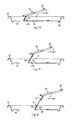
- a container 10 is represented by a can to contain a substance, such as for example a drink.
- the container 10 is made for example of aluminum, steel or alloys thereof, it is substantially cylindrical in shape and has an external lateral surface 40, an upper wall 11, which functions as a lid, and a bottom, of any type, known, and not shown in the drawings.
- the upper wall 11 is substantially circular in shape ( figs. 2 and 3 ), concentric with respect to a central axis Y ( figs. 1 to 15 ). Furthermore, the upper wall 11 has a peripheral rib 12 of annular shape, which delimits a central zone 36 having a determinate radius A.
- a groove 38 is made on the upper wall 11 and, in the form of embodiment shown in figs. 1 to 15 , is defined by a circular closed line, concentric to the peripheral rib 12.
- a line of weakening 13 ( fig. 2 ) is made, in a known manner, closed on itself, having a locally reduced or variable cross section, which delimits a closing element or stopper 14 in the shape of a tongue.
- the stopper 14 normally closes a corresponding aperture 15 through which the substance can be removed from the container 10.
- the stopper 14 closes the aperture 15 completely and hermetically, whereas in an open condition it is raised and at least partly removed from the aperture 15 ( fig. 3 ), although it remains solid with the remaining part of the container 10.
- the stopper 14 as will be shown in more detail hereafter in the description, is solidly attached to a lever 16 which, in the closed condition ( fig. 2 ), at least partly overlaps the stopper 14.
- the lever 16 is driven manually, by means of a gripping end thereof, or ring 32, to separate the stopper 14 from the remaining part of the upper wall 11, along the line of weakening 13.
- the ring 32 faces towards the inside of the upper wall 11, that is, towards the central zone 36, to make it easier to grip and drive the lever 16.
- the ring 32 is substantially in correspondence with the central axis Y passing through the center of the central zone 36.
- the lever 16 is pivoted on one end 34 ( fig. 1 ) opposite the ring 32, that is, disposed substantially in correspondence with the peripheral rib 12.
- the end 34 in the closed condition ( fig. 2 ) the end 34 is outside the line of weakening 13 and rests in direct contact on a ridge 35, facing upwards and made on the upper wall 11.
- the ridge 35 is substantially U-shaped, that is, with two rectilinear segments, opposite and parallel, connected by a curved segment, nearer the peripheral rib 12.
- the curved segment of the ridge 35 is at least partly comprised between the peripheral rib 12 and the line of weakening 13 and at least partly surrounds both the stopper 14 and the corresponding aperture 15, and also the lever 16.
- the end 34 of the lever 16 rests on the curved segment of the ridge 35 ( fig. 1 ).
- the lever 16 comprises an intermediate zone 39 ( fig. 1 ), comprised between its ends 32 and 34, to which a flexible tongue 17 is attached, which is in turn connected to the stopper 14.
- the intermediate zone 39 is advantageously nearer the end 34, which functions as a fulcrum and, in particular is attached for example by means of welding to an end 18 of the tongue 17.
- the tongue 17 is normally positioned on the upper wall 11, interposed between the lever 16 and the stopper 14 ( fig. 1 ).
- the tongue 17 has an extension such as to cover the whole stopper 14 and is attached to it by means of a rivet 20 ( fig. 1 ).
- the tongue 17 has an end 19 ( fig. 2 ), normally positioned in correspondence with the central zone 36, by means of which it is solidly attached to the upper wall 11, for example with a rivet 37.
- the tongue 17 is also provided with five lines of predetermined bending, respectively 21, 22, 23, 24 and 25, which delimit relative portions thereof 26, 27, 28, 29, 30 and 31.
- the first line of bending 21 delimits the portion 26 ( fig. 9 ), in substantial correspondence with the end 18 of the tongue 17, which functions as a connection element with the lever 16. In this way, since the tongue 17 is in turn solidly attached to the stopper 14, a connection is achieved between the stopper 14 and the lever 16.
- the second line of bending 22 defines the portion 27 ( figs. 8 and 9 ), which is adjacent to the portion 26 and is attached to the stopper 14 by means of the rivet 20.
- the third line of bending 23 defines the portion 28 ( fig. 11 ), which is disposed adjacent to the portion 27, while the fourth line of bending 24 defines the portion 29 ( fig. 12 ), which is disposed adjacent to the portion 28.
- the fifth line of bending defines the portion 31 ( figs. 13 and 14 ), in correspondence with the end 19 of the tongue 17 and in a position opposite to the portion 26.
- the portion 31 is attached to the upper wall 11 by means of the rivet 37.
- the lever 16 which acts on the stopper 14 defines an extremely favorable arm that allows, with limited force, to apply a high angular moment.
- the force of the lever 16 is applied at a point of application in close proximity with the line of weakening 13 and with a rotation towards the outside of the container 10.
- the resistant section of the line of weakening 13 on which the lever 16 acts is much smaller than the remaining part of the line of weakening 13. Therefore, from the above, it is clear that the force necessary to lift the stopper 14 along the line of weakening 13 is much less compared with containers with a hygienic stopper that are known in the state of the art.
- a further distancing upwards of the end 34 of the lever 16 allows to remove the stopper 14 completely from the upper wall 11 and to position the flexible tongue 17 in its bent configuration.
- the flexible tongue 17 is positioned above the upper wall 11 and at the side of the aperture 15, while its portions 26, 27, 28, 29, 30, 31 are substantially parallel to the wall 11 and overlapping each other.
- the portion 26 is in an upper position, immediately below the lever 16, while the portion 31 is below all the other portions 26, 27, 28, 29 and 30, in contact with the upper wall 11. Consequently, in the bent configuration of the flexible tongue 17, the portions 27, 28, 29 and 30 are positioned between the portion 26 and the portion 31, as can be clearly seen in figs. 14 and 15 .
- the rivet 20, cooperating with one edge of the lever 16, also selectively keeps the flexible tongue 17 in its bent configuration.
- stopper 14 since it is solid with the tongue 17, is also able to bend into relative portions, which are positioned one above the other, in correspondence with the intermediate lines of bending 22, 23 and 24 of the tongue 17.
- the portions 26, 27, 28, 29, 30 and 31 overlap each other concertina-wise, and the lever 16 is positioned above them.
- the lever 16 does not protrude excessively from the container 10, and neither the lever 16 nor the tongue 17, nor the stopper 14 are an impediment to the user who wants to remove the substance from the container 10.
- the container 10 as described heretofore is used as follows.
- the container 10 is normally in its closed condition ( figs. 2 and 4 ).
- the user has to grip the ring 32 of the lever 16 and rotate it in the direction of rotation indicated by the arrow R in figs. 5, 6 and 7 , around its end 34.
- This causes a part of the stopper 14 to be detached from the remaining part of the upper wall 11, and also the consequent definition of a part of the aperture 15, in correspondence with the portion 27, and the bending of the stopper 14 and the tongue 17, along the line of bending 22.
- the stopper 14 is lifted upwards and therefore never enters into contact with the substance contained in the container 10, guaranteeing that the optimum hygienic conditions under which the substance was inserted into the container 10 are maintained.
- the lever 16, the stopper 14 and the flexible tongue 17 are easily repositioned several times in the closed condition, allowing the user to close the container 10 with the stopper 14 as desired and temporarily.
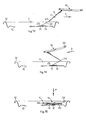
- a container 110 that is not part of the present invention, shown in figs. 16 and 17 , where the same reference numbers correspond to equivalent parts, comprises a groove 138, made on the upper wall 11, which instead of being closed like the groove 38, is open, that is, interrupted in correspondence with the stopper 14 and the aperture 15. In this way the substance contained in the container 110, once it has come out, is prevented from stagnating, partly, in the groove 138, creating unhygienic conditions.
- the lever 16 is provided with a gripping ring of double size with respect to the ring 32, so as to be able to drive the lever 16 more easily with two fingers, instead of one, as normally happens.
- a container 210 has an upper wall 211 provided with a peripheral rib 212 of annular shape, which delimits a central zone 236.
- a groove 238, analogous to the groove 38, is made on the upper wall 211.
- a line of weakening 213 is made on the central zone 236, which is not closed on itself and which delimits a closing element or stopper 214, in the form of a tongue, always integral with the remaining part of the central part 236, even when it is in the open condition ( figs. 22 and 23 ).
- the stopper 214 ( fig. 24 ) comprises a first part 214a substantially circular in shape, and a second part 214b substantially rectangular in shape and contiguous to the first part 214a.
- the stopper 214 normally closes a corresponding aperture 215 and is solidly attached to a lever 216 which, in the closed condition ( figs. 18 and 19 ), is at least partly overlapping therewith.
- the lever 216 is driven manually, by means of a gripping end thereof, or ring 232, to separate the stopper 214 from the remaining part of the central zone 236 of the upper wall 211, along the line of weakening 213.
- the lever 216 is pivoted at one end 234 ( fig. 18 ) opposite the ring 232, that is, disposed substantially in correspondence with the peripheral rib 212.
- the lever 216 comprises an intermediate zone 239 ( fig. 18 ), comprised between its ends 232 and 234 on which a flexible tongue 251 is made, which is in turn connected to the stopper 214 by means of a rivet 250.
- the intermediate zone 239 is advantageously nearer the end 234, which functions as a fulcrum.
- the stopper 214 is removed as follows: firstly the ring 232 of the lever 216 is lifted manually towards the outside of the container 210, pivoting on its first end 214, so that the intermediate zone 239 of the lever 216 partly detaches the stopper 214 from the remaining part of the central zone 236 ( figs. 20 and 21 ), along the line of weakening 213; then the ring 232 is pulled back so as to lift the stopper 214 and continue to detach it along the line of weakening 213, until the aperture 215 is completely open ( figs. 22 and 23 ).
- Fig. 25 shows a third form of embodiment of a container 310 that is not part of the present invention, which comprises an upper wall 311 provided with a peripheral rib 312 of annular shape, which delimits a central zone 336.
- a groove 338 is made on the upper wall 311.
- a line of weakening 313 is made on the central zone 336, which (like the line 213) is not closed on itself and which delimits a closing element or stopper 314, in the form of a tongue, always integral with the remaining part of the central part 336, even when it is in the open condition.
- the stopper 314 has a substantially rectangular shape, it normally closes a corresponding aperture 315 and is solidly attached to a lever 316 which, in the closed condition, is at least partly overlapping therewith.
- the lever 316 is driven manually, by means of a gripping end thereof, or ring 332, to separate the stopper 314 from the remaining part of the central zone 336 of the upper wall 311, along the line of weakening 313.
- the lever 316 is pivoted at one end 334 opposite the ring 332, that is, disposed substantially in correspondence with the center of the central zone 336.
- the lever 316 comprises an intermediate zone 339 comprised between its ends 332 and 334 on which a flexible tongue 351 is made, which is in turn connected to the stopper 314 by means of a rivet 350.
- the stopper 314 is removed as follows: firstly the ring 332 of the lever 316 is lifted manually, bending it towards the center of the upper wall 311, pivoting on its first end 314, so that the intermediate zone 339 of the lever 316 partly detaches the stopper 314 from the remaining part of the central zone 336, along the line of weakening 313; then the ring 332 is further pulled back and on the same side so as to lift the stopper 314 and continue to detach it along the line of weakening 313, until the aperture 315 is completely open.
Landscapes
- Engineering & Computer Science (AREA)
- Mechanical Engineering (AREA)
- Closures For Containers (AREA)
- Packages (AREA)
- Containers Opened By Tearing Frangible Portions (AREA)
- Details Of Rigid Or Semi-Rigid Containers (AREA)
Claims (11)
- Récipient pour une substance, en particulier une boisson, comprenant au moins : une paroi supérieure (211) faisant office de couvercle, dotée d'une nervure périphérique (212) délimitant une zone centrale (236) de forme sensiblement circulaire et de rayon défini (A), concentrique par rapport à un axe central (Y), solidaire de ladite nervure périphérique (212) et sur laquelle est ménagée une ligne de faiblesse interrompue (213), laquelle définit un élément de fermeture (214) à tirette d'ouverture, formé toujours d'un seul tenant avec la partie restante de la partie centrale (236) et pourvu d'une partie terminale avant adjacente à ladite nervure périphérique (212), l'élément de fermeture (214) faisant office de bouchon amovible d'une ouverture associée (215) ménagée dans ladite zone centrale (236) et destinée à laisser passer ladite substance ; et un levier (216) dont une partie au moins est reliée audit élément de fermeture (214) et qui peut être manipulé de manière à retirer, au moins partiellement, ledit élément de fermeture (214) de la partie restante de ladite zone centrale (236), en le détachant suivant ladite ligne de faiblesse (213) et en mettant ainsi ladite ouverture (215) en contact avec l'extérieur, ladite ligne de faiblesse (213) étant interrompue à une extrémité dudit élément de fermeture (214), placé du côté opposé dudit levier (16) par rapport audit axe central (Y), de sorte qu'un bord dudit élément de fermeture (214) reste solidaire de la partie restante de ladite zone centrale (236), caractérisé en ce que ledit levier (216) comprend :- une première extrémité (234) ayant une partie centrale faisant office de point d'appui placé au niveau de ladite nervure périphérique (212), à l'extérieur dudit élément de fermeture (214) défini par ladite ligne de faiblesse (213) et en face de ladite partie terminale avant, ledit point d'appui pouvant définir le soulèvement par traction dudit élément de fermeture (214) ;- une seconde extrémité (232) placée sensiblement au niveau de ladite zone centrale (236), à l'opposé de ladite première extrémité (234) et faisant office d'élément de préhension, de soulèvement et de traction, la distance entre ladite première extrémité (234) et ladite seconde extrémité (232) étant légèrement inférieure à la longueur dudit rayon (A) ;- et une zone intermédiaire (239) entre ladite première extrémité (234) et ladite seconde extrémité (232), par laquelle ledit levier (216) est relié audit élément de fermeture (214), ladite zone intermédiaire (239) dudit levier (216) comprenant une languette flexible (251) reliée mécaniquement audit élément de fermeture (214) par la partie terminale ayant de celui-ci, afin de soulever et de détacher cette dernière de la partie restante de la partie centrale (236) sans qu'aucune partie de l'élément de fermeture (214) n'entre en contact avec la substance contenue dans le récipient.
- Récipient selon la revendication 1, caractérisé en ce que ledit levier (216) est sensiblement parallèle audit rayon (A).
- Récipient selon la revendication 2, caractérisé en ce que ladite seconde extrémité (232) est placée à proximité dudit axe central (Y).
- Récipient selon la revendication 2 ou 3, caractérisé en ce que ledit élément de fermeture (214) défini par ladite ligne de faiblesse (213) comporte une languette ayant une première partie (214a) de forme sensiblement circulaire, et une seconde partie (214b) de forme sensiblement rectangulaire et contigüe à ladite première partie (214a), laquelle comprend ladite partie terminale avant.
- Récipient selon la revendication 4, caractérisé en ce que ledit levier (216) est placé au-dessus de ladite première partie (214a) dudit élément de fermeture (214).
- Récipient selon la revendication 4 ou 5, caractérisé en ce que ladite ligne de faiblesse (213) est interrompue à l'extrémité de ladite seconde partie (214b) se trouvant du côté opposé dudit levier (216) par rapport audit axe central (Y), de sorte qu'un bord dudit élément de fermeture (214) reste solidaire de la partie restante de ladite zone centrale (236).
- Récipient selon la revendication 4, 5 ou 6, caractérisé en ce que ladite languette flexible (251) est reliée mécaniquement à ladite partie terminale avant dudit élément de fermeture (214) par un moyen de liaison mécanique (250).
- Récipient selon la revendication 7, caractérisé en ce que ledit moyen de liaison mécanique (250) est un rivet ou un point de soudure.
- Récipient selon l'une quelconque des revendications précédentes, caractérisé en ce que ledit levier (216) peut être tourné vers l'extérieur de ladite nervure périphérique (212).
- Couvercle pour un récipient apte à contenir une substance, en particulier une boisson, comprenant : une nervure périphérique (212) délimitant une zone centrale (236) de forme sensiblement circulaire et de rayon défini (A), concentrique par rapport à un axe central (Y), solidaire de ladite nervure périphérique (212) et sur laquelle est ménagée une ligne de faiblesse interrompue (213), laquelle définit un élément de fermeture (214) à tirette d'ouverture, formé toujours d'un seul tenant avec la partie restante de la partie centrale (236) et pourvu d'une partie terminale avant adjacente à ladite nervure périphérique (212), l'élément de fermeture (214) faisant office de bouchon amovible d'une ouverture associée (215) ménagée dans ladite zone centrale (236) et destinée à laisser passer ladite substance ; et un levier (216) dont une partie au moins est reliée audit élément de fermeture (214) et qui peut être manipulé de manière à retirer, au moins partiellement, ledit élément de fermeture (214) de la partie restante de ladite zone centrale (236), en le détachant suivant ladite ligne de faiblesse (213) et en mettant ainsi ladite ouverture (215) en contact avec l'extérieur, ladite ligne de faiblesse (213) étant interrompue à une extrémité dudit élément de fermeture (214), placé du côté opposé dudit levier (16) par rapport audit axe central (Y), de sorte qu'un bord dudit élément de fermeture (214) reste solidaire de la partie restante de ladite zone centrale (236), caractérisé en ce que ledit levier (216) comprend :- une première extrémité (234) ayant une partie centrale faisant office de point d'appui placé au niveau de ladite nervure périphérique (212), à l'extérieur dudit élément de fermeture (214) défini par ladite ligne de faiblesse (213) et en face de ladite partie terminale avant, ledit point d'appui pouvant définir le soulèvement par traction dudit élément de fermeture (214) ;- une seconde extrémité (232) placée sensiblement au niveau de ladite zone centrale (236), à l'opposé de ladite première extrémité (234) et faisant office d'élément de préhension, de soulèvement et de traction, la distance entre ladite première extrémité (234) et ladite seconde extrémité (232) étant légèrement inférieure à la longueur dudit rayon (A) ;- et une zone intermédiaire (239) entre ladite première extrémité (234) et ladite seconde extrémité (232), par laquelle ledit levier (216) est relié audit élément de fermeture (214), ladite zone intermédiaire (239) dudit levier (216) comprenant une languette flexible (251) reliée mécaniquement audit élément de fermeture (214) par la partie terminale avant de celui-ci, afin de soulever et de détacher cette dernière de la partie restante de la partie centrale (236) sans qu'aucune partie de l'élément de fermeture (214) n'entre en contact avec la substance contenue dans le récipient et en gardant l'élément de fermeture (214) toujours solidaire de la partie restante de la zone centrale (236).
- Procédé d'ouverture d'un élément de fermeture (214) d'un récipient apte à contenir une substance, en particulier une boisson, dans lequel ledit récipient comprend une paroi supérieure (211) faisant office de couvercle, dotée d'une nervure périphérique (212) délimitant une zone centrale (236) de forme sensiblement circulaire et de rayon défini (A), concentrique par rapport à un axe central (Y), solidaire de ladite nervure périphérique (212) et sur laquelle est ménagée une ligne de faiblesse interrompue (213), laquelle définit ledit élément de fermeture (214) à tirette d'ouverture, formé toujours d'un seul tenant avec la partie restante de la partie centrale (236) et pourvu d'une partie terminale avant adjacente à ladite nervure périphérique (212), l'élément de fermeture (214) faisant office de bouchon amovible d'une ouverture associée (215) ménagée dans ladite zone centrale (236) et destinée à laisser passer ladite substance ; et un levier (216) dont une partie au moins est reliée audit élément de fermeture (214) et qui peut être manipulé de manière à retirer par traction, au moins partiellement, ledit élément de fermeture (214) de la partie restante de ladite zone centrale (236), en le détachant suivant ladite ligne de faiblesse (213), celle-ci étant interrompue à une extrémité dudit élément de fermeture (214) se trouvant du côté opposé dudit levier (16) par rapport audit axe central (Y), de sorte qu'un bord dudit élément de fermeture (214) reste solidaire de la partie restante de ladite zone centrale (236) ; dans lequel ledit levier (216) comprend :- une première extrémité (234) ayant une partie centrale dotée d'un point d'appui placé au niveau de ladite nervure périphérique (212), à l'extérieur dudit élément de fermeture (214) défini par ladite ligne de faiblesse (213) et en face de ladite partie terminale avant, ledit point d'appui pouvant définir le soulèvement par traction dudit élément de fermeture (214) sans que ce dernier ne rentre à l'intérieur du récipient ;- une seconde extrémité (232) placée sensiblement au niveau de ladite zone centrale (236), à l'opposé de ladite première extrémité (234) et faisant office d'élément de préhension, de soulèvement et de traction, la distance entre ladite première extrémité (234) et ladite seconde extrémité (232) étant légèrement inférieure à la longueur dudit rayon (A) ;- et une zone intermédiaire (239) entre ladite première extrémité (234) et ladite seconde extrémité (232), par laquelle ledit levier (216) est relié audit élément de fermeture (214), ladite zone intermédiaire (239) dudit levier (216) comprenant une languette flexible (251) reliée mécaniquement audit élément de fermeture (214) par la partie terminale avant de celui-ci, ledit procédé comprenant les étapes suivantes :- soulever ladite seconde extrémité (232) dudit levier (216), le tourner vers l'extérieur de ladite nervure périphérique (212) en le faisant pivoter sur sa première extrémité (234), de sorte que ladite languette flexible (251) de ladite zone intermédiaire (239) soulève et détache la partie terminale avant dudit élément de fermeture (214) de la partie restante de la zone centrale (236), sans qu'aucune partie de l'élément de fermeture (214) n'entre en contact avec la substance contenue dans le récipient, et en gardant l'élément de fermeture (214) toujours solidaire de la partie restante de la zone centrale (236) ; et- tirer vers l'arrière ladite seconde extrémité dudit levier (216) de manière à soulever ledit élément de fermeture (214) et à continuer de le détacher suivant ladite ligne de faiblesse (213), en gardant l'élément de fermeture (214) toujours solidaire de la partie restante de la zone centrale (236) jusqu'à ce que ladite ouverture (215) soit ouverte.
Priority Applications (3)
| Application Number | Priority Date | Filing Date | Title |
|---|---|---|---|
| SI200830648T SI2200903T1 (sl) | 2007-09-07 | 2008-05-08 | Vsebnik za snov še zlasti pijačo z zapornim elementom ki se odpre z odtrganjem |
| PL08750201T PL2200903T3 (pl) | 2007-09-07 | 2008-05-08 | Pojemnik na substancję, w szczególności na napój, z otwieranym przez odrywanie elementem zamykającym |
| CY20121100505T CY1113041T1 (el) | 2007-09-07 | 2012-06-06 | Υποδοχεας για μια ουσια, eιδικοτερα ενα ποτο, με ενα αποσχιζομενο στοιχειο κλεισιματος |
Applications Claiming Priority (2)
| Application Number | Priority Date | Filing Date | Title |
|---|---|---|---|
| IT000159A ITUD20070159A1 (it) | 2007-09-07 | 2007-09-07 | Contenitore per una sostanza, in particolare una bevanda, con elemento di chiusura apribile a strappo |
| PCT/EP2008/055707 WO2009030526A1 (fr) | 2007-09-07 | 2008-05-08 | Récipient à ouverture déchirable pour une substance, en particulier une boisson |
Publications (2)
| Publication Number | Publication Date |
|---|---|
| EP2200903A1 EP2200903A1 (fr) | 2010-06-30 |
| EP2200903B1 true EP2200903B1 (fr) | 2012-03-07 |
Family
ID=39673461
Family Applications (1)
| Application Number | Title | Priority Date | Filing Date |
|---|---|---|---|
| EP08750201A Active EP2200903B1 (fr) | 2007-09-07 | 2008-05-08 | Recipient a ouverture dechirable pour une substance, en particulier une boisson |
Country Status (24)
| Country | Link |
|---|---|
| US (1) | US8336727B2 (fr) |
| EP (1) | EP2200903B1 (fr) |
| JP (1) | JP5430010B2 (fr) |
| CN (1) | CN101801800B (fr) |
| AT (1) | ATE548277T1 (fr) |
| AU (1) | AU2008295021B2 (fr) |
| BR (1) | BRPI0816397B1 (fr) |
| CA (1) | CA2698479C (fr) |
| CY (1) | CY1113041T1 (fr) |
| DK (1) | DK2200903T3 (fr) |
| EG (1) | EG26035A (fr) |
| ES (1) | ES2383926T3 (fr) |
| HK (1) | HK1146925A1 (fr) |
| IL (1) | IL204315A (fr) |
| IT (1) | ITUD20070159A1 (fr) |
| MA (1) | MA31825B1 (fr) |
| MX (1) | MX2010002597A (fr) |
| MY (1) | MY161989A (fr) |
| PL (1) | PL2200903T3 (fr) |
| PT (1) | PT2200903E (fr) |
| RS (1) | RS52322B (fr) |
| RU (1) | RU2482037C2 (fr) |
| SI (1) | SI2200903T1 (fr) |
| WO (1) | WO2009030526A1 (fr) |
Families Citing this family (12)
| Publication number | Priority date | Publication date | Assignee | Title |
|---|---|---|---|---|
| IT1394648B1 (it) | 2009-07-03 | 2012-07-05 | Internat Patents And Brands Corp | Coperchio per contenitori di sostanze e contenitore di sostanze cosi' attrezzato |
| US10017295B2 (en) | 2010-08-06 | 2018-07-10 | Ball Corporation | Container end closure with optional secondary vent opening |
| US20130284742A1 (en) * | 2012-04-25 | 2013-10-31 | Alan Jung | Easy Open Lid |
| EP2844573B1 (fr) * | 2012-05-04 | 2017-08-23 | Ball Corporation | Élément de fermeture d'extrémité métallique comportant une section déchirable présentant une rigidité améliorée |
| JP2015526353A (ja) * | 2012-08-24 | 2015-09-10 | ストール マシーナリ カンパニー, エルエルシーStolle Machinery Company, LLC | イージー注ぎ口 |
| WO2014149768A1 (fr) | 2013-03-15 | 2014-09-25 | Ball Corporation | Fermeture d'extrémité ayant une évacuation secondaire actionnée par traction d'une bague |
| CA2936325C (fr) * | 2014-01-08 | 2022-11-29 | International Patents And Brands Corporation | Couvercle contenants de substances et contenant de substances comprenant ce couvercle |
| MX357385B (es) | 2014-07-30 | 2018-07-06 | Ball Corp | Recipiente ventilado y cierre. |
| PL3544899T3 (pl) | 2016-11-25 | 2021-07-05 | João Marques FERNANDES | Rozwiązanie konstrukcyjne dla otwierania puszki z napojem |
| PL3548391T3 (pl) * | 2016-12-01 | 2021-12-13 | João Marques FERNANDES | Rozwiązanie konstrukcyjne dla otwierania puszki z napojem |
| JP6942285B1 (ja) * | 2020-01-10 | 2021-09-29 | 株式会社Ky7 | 蓋体 |
| CN116323410A (zh) | 2020-07-13 | 2023-06-23 | Oc Bev有限公司 | 用于物质的容器的盖子和包括所述盖子的物质的容器 |
Family Cites Families (15)
| Publication number | Priority date | Publication date | Assignee | Title |
|---|---|---|---|---|
| US3478918A (en) * | 1968-08-14 | 1969-11-18 | American Can Co | Full open end closure |
| BE790950A (fr) * | 1971-11-03 | 1973-03-01 | Nat Can Corp | Fermeture de fond de recipient s'ouvrant entierement |
| US3730380A (en) * | 1972-01-17 | 1973-05-01 | Fraze Ermal C | Can end with inseparable tear strip and latch means for holding tear strip against can wall |
| US3731836A (en) * | 1972-03-17 | 1973-05-08 | Fraze Ermal C | Container wall with connector for retaining the tab and tear portion on the container wall |
| US3877606A (en) * | 1972-04-20 | 1975-04-15 | Fraze Ermal C | Easy opening container wall with retained tear strip |
| US3795340A (en) | 1972-08-04 | 1974-03-05 | Continental Can Co | Tab mounting arrangement for easy opening can end |
| US4189060A (en) * | 1978-10-05 | 1980-02-19 | Minnesota Mining And Manufacturing Company | Retention means for container closure assembly |
| US4203528A (en) * | 1979-04-30 | 1980-05-20 | The Continental Group, Inc. | Self-storing pull strip for easy opening containers |
| US4417668A (en) * | 1981-09-03 | 1983-11-29 | Stolle Research And Development Corporation | Easy open can end with pull tab having retained tear strip with stress relief means |
| US4687116A (en) * | 1986-09-10 | 1987-08-18 | Sun Coast Plastics, Inc. | Easy open container end closure |
| FR2675467B1 (fr) * | 1991-04-16 | 1995-02-17 | Lorraine Laminage | Couvercle a ouverture partielle pour boite metallique. |
| US5145086A (en) * | 1991-05-17 | 1992-09-08 | Krause Arthur A | Captive tear tab with protective means for container opening |
| IT1280461B1 (it) * | 1995-09-11 | 1998-01-20 | Cesare Mongarli | Contenitore, particolarmente per bevande. |
| KR100302638B1 (ko) * | 1999-07-05 | 2001-11-07 | 조성호 | 오픈기능성 및 위생성이 개선된 캔 개봉수단을 가지는 캔뚜껑 |
| CN2436439Y (zh) * | 2000-06-13 | 2001-06-27 | 杜依民 | 环保型易拉罐 |
-
2007
- 2007-09-07 IT IT000159A patent/ITUD20070159A1/it unknown
-
2008
- 2008-05-08 BR BRPI0816397-9A patent/BRPI0816397B1/pt active IP Right Grant
- 2008-05-08 MX MX2010002597A patent/MX2010002597A/es active IP Right Grant
- 2008-05-08 DK DK08750201.9T patent/DK2200903T3/da active
- 2008-05-08 AU AU2008295021A patent/AU2008295021B2/en active Active
- 2008-05-08 ES ES08750201T patent/ES2383926T3/es active Active
- 2008-05-08 RS RS20120239A patent/RS52322B/en unknown
- 2008-05-08 CN CN2008801060661A patent/CN101801800B/zh active Active
- 2008-05-08 MY MYPI2010000954A patent/MY161989A/en unknown
- 2008-05-08 US US12/677,016 patent/US8336727B2/en active Active
- 2008-05-08 WO PCT/EP2008/055707 patent/WO2009030526A1/fr active Application Filing
- 2008-05-08 EP EP08750201A patent/EP2200903B1/fr active Active
- 2008-05-08 RU RU2010112488/12A patent/RU2482037C2/ru active
- 2008-05-08 CA CA2698479A patent/CA2698479C/fr active Active
- 2008-05-08 AT AT08750201T patent/ATE548277T1/de active
- 2008-05-08 SI SI200830648T patent/SI2200903T1/sl unknown
- 2008-05-08 JP JP2010523446A patent/JP5430010B2/ja active Active
- 2008-05-08 PL PL08750201T patent/PL2200903T3/pl unknown
- 2008-05-08 PT PT08750201T patent/PT2200903E/pt unknown
-
2010
- 2010-03-04 IL IL204315A patent/IL204315A/en active IP Right Grant
- 2010-03-07 EG EG2010030366A patent/EG26035A/en active
- 2010-04-01 MA MA32734A patent/MA31825B1/fr unknown
-
2011
- 2011-02-01 HK HK11101059.3A patent/HK1146925A1/xx unknown
-
2012
- 2012-06-06 CY CY20121100505T patent/CY1113041T1/el unknown
Also Published As
| Publication number | Publication date |
|---|---|
| BRPI0816397B1 (pt) | 2019-06-18 |
| ITUD20070159A1 (it) | 2007-12-07 |
| RU2482037C2 (ru) | 2013-05-20 |
| CN101801800A (zh) | 2010-08-11 |
| DK2200903T3 (da) | 2012-07-02 |
| MX2010002597A (es) | 2010-06-01 |
| US8336727B2 (en) | 2012-12-25 |
| WO2009030526A1 (fr) | 2009-03-12 |
| CA2698479A1 (fr) | 2009-03-12 |
| PL2200903T3 (pl) | 2012-08-31 |
| EP2200903A1 (fr) | 2010-06-30 |
| ES2383926T3 (es) | 2012-06-27 |
| MY161989A (en) | 2017-05-31 |
| IL204315A (en) | 2014-06-30 |
| AU2008295021A1 (en) | 2009-03-12 |
| SI2200903T1 (sl) | 2012-07-31 |
| RS52322B (en) | 2012-12-31 |
| MA31825B1 (fr) | 2010-11-01 |
| BRPI0816397A2 (pt) | 2018-07-31 |
| HK1146925A1 (en) | 2011-07-22 |
| ATE548277T1 (de) | 2012-03-15 |
| AU2008295021A2 (en) | 2010-05-06 |
| CN101801800B (zh) | 2012-07-11 |
| CY1113041T1 (el) | 2016-04-13 |
| EG26035A (en) | 2012-12-19 |
| CA2698479C (fr) | 2015-04-14 |
| JP2010537905A (ja) | 2010-12-09 |
| US20100258562A1 (en) | 2010-10-14 |
| AU2008295021B2 (en) | 2013-03-28 |
| PT2200903E (pt) | 2012-06-18 |
| RU2010112488A (ru) | 2011-10-20 |
| JP5430010B2 (ja) | 2014-02-26 |
Similar Documents
| Publication | Publication Date | Title |
|---|---|---|
| EP2200903B1 (fr) | Recipient a ouverture dechirable pour une substance, en particulier une boisson | |
| US3977561A (en) | Can end with nondetachable tear tab and opening ring | |
| US6290084B1 (en) | Rotary protective cover attachment for beverage container | |
| EP0220820B1 (fr) | Boîte métallique avec fermeture en plastique | |
| US3225957A (en) | Metal end closure | |
| US8870012B2 (en) | Flip-up pop-top can lid | |
| CA2766969C (fr) | Couvercle pour receptacles de substances et receptacle pour substances ainsi equipe | |
| AU2001273746B2 (en) | Can lid | |
| US20130299497A1 (en) | Lid for beverage can | |
| EP0221913A1 (fr) | Fermeture facile a ouvrir | |
| EP3912923A1 (fr) | Couvercle de fermeture pour un récipient à ouverture facile | |
| EP0090809B1 (fr) | Fermeture pour recipients | |
| JP2000190963A (ja) | 開口容易な缶蓋 | |
| JPH0234186Y2 (fr) | ||
| NL8302045A (nl) | Openscheur deksel, in het bijzonder van plaatstaal, voor blikken. | |
| JPH07172436A (ja) | 開口容易な缶蓋 | |
| EP2493775B1 (fr) | Couvercle pour récipients, tels que des boîtes et autres | |
| KR20230071119A (ko) | 물질의 용기용 뚜껑, 및 상기 뚜껑을 포함하는 물질의 용기 | |
| CA2023588C (fr) | Couvercle pour boite metallique | |
| WO1997027117A1 (fr) | Boite-boisson refermable | |
| JPH04114858A (ja) | 缶容器の開口装置 |
Legal Events
| Date | Code | Title | Description |
|---|---|---|---|
| PUAI | Public reference made under article 153(3) epc to a published international application that has entered the european phase |
Free format text: ORIGINAL CODE: 0009012 |
|
| 17P | Request for examination filed |
Effective date: 20100406 |
|
| AK | Designated contracting states |
Kind code of ref document: A1 Designated state(s): AT BE BG CH CY CZ DE DK EE ES FI FR GB GR HR HU IE IS IT LI LT LU LV MC MT NL NO PL PT RO SE SI SK TR |
|
| AX | Request for extension of the european patent |
Extension state: AL BA MK RS |
|
| 17Q | First examination report despatched |
Effective date: 20101007 |
|
| R17C | First examination report despatched (corrected) |
Effective date: 20101007 |
|
| GRAP | Despatch of communication of intention to grant a patent |
Free format text: ORIGINAL CODE: EPIDOSNIGR1 |
|
| RIN1 | Information on inventor provided before grant (corrected) |
Inventor name: CAMURRI, EDMONDO Inventor name: LINDEN, PAOLO |
|
| GRAS | Grant fee paid |
Free format text: ORIGINAL CODE: EPIDOSNIGR3 |
|
| GRAA | (expected) grant |
Free format text: ORIGINAL CODE: 0009210 |
|
| AK | Designated contracting states |
Kind code of ref document: B1 Designated state(s): AT BE BG CH CY CZ DE DK EE ES FI FR GB GR HR HU IE IS IT LI LT LU LV MC MT NL NO PL PT RO SE SI SK TR |
|
| AX | Request for extension of the european patent |
Extension state: AL BA MK RS |
|
| REG | Reference to a national code |
Ref country code: GB Ref legal event code: FG4D |
|
| REG | Reference to a national code |
Ref country code: AT Ref legal event code: REF Ref document number: 548277 Country of ref document: AT Kind code of ref document: T Effective date: 20120315 Ref country code: CH Ref legal event code: EP |
|
| REG | Reference to a national code |
Ref country code: IE Ref legal event code: FG4D |
|
| REG | Reference to a national code |
Ref country code: DE Ref legal event code: R096 Ref document number: 602008013964 Country of ref document: DE Effective date: 20120503 |
|
| REG | Reference to a national code |
Ref country code: RO Ref legal event code: EPE |
|
| REG | Reference to a national code |
Ref country code: CH Ref legal event code: NV Representative=s name: MICHELI & CIE SA |
|
| REG | Reference to a national code |
Ref country code: PT Ref legal event code: SC4A Free format text: AVAILABILITY OF NATIONAL TRANSLATION Effective date: 20120606 |
|
| REG | Reference to a national code |
Ref country code: SE Ref legal event code: TRGR |
|
| REG | Reference to a national code |
Ref country code: NL Ref legal event code: T3 |
|
| REG | Reference to a national code |
Ref country code: ES Ref legal event code: FG2A Ref document number: 2383926 Country of ref document: ES Kind code of ref document: T3 Effective date: 20120627 |
|
| REG | Reference to a national code |
Ref country code: DK Ref legal event code: T3 |
|
| REG | Reference to a national code |
Ref country code: NO Ref legal event code: T2 Effective date: 20120307 |
|
| PG25 | Lapsed in a contracting state [announced via postgrant information from national office to epo] |
Ref country code: HR Free format text: LAPSE BECAUSE OF FAILURE TO SUBMIT A TRANSLATION OF THE DESCRIPTION OR TO PAY THE FEE WITHIN THE PRESCRIBED TIME-LIMIT Effective date: 20120307 Ref country code: LT Free format text: LAPSE BECAUSE OF FAILURE TO SUBMIT A TRANSLATION OF THE DESCRIPTION OR TO PAY THE FEE WITHIN THE PRESCRIBED TIME-LIMIT Effective date: 20120307 |
|
| LTIE | Lt: invalidation of european patent or patent extension |
Effective date: 20120307 |
|
| PG25 | Lapsed in a contracting state [announced via postgrant information from national office to epo] |
Ref country code: LV Free format text: LAPSE BECAUSE OF FAILURE TO SUBMIT A TRANSLATION OF THE DESCRIPTION OR TO PAY THE FEE WITHIN THE PRESCRIBED TIME-LIMIT Effective date: 20120307 |
|
| REG | Reference to a national code |
Ref country code: PL Ref legal event code: T3 |
|
| REG | Reference to a national code |
Ref country code: GR Ref legal event code: EP Ref document number: 20120401293 Country of ref document: GR Effective date: 20120713 Ref country code: SK Ref legal event code: T3 Ref document number: E 11969 Country of ref document: SK |
|
| PG25 | Lapsed in a contracting state [announced via postgrant information from national office to epo] |
Ref country code: EE Free format text: LAPSE BECAUSE OF FAILURE TO SUBMIT A TRANSLATION OF THE DESCRIPTION OR TO PAY THE FEE WITHIN THE PRESCRIBED TIME-LIMIT Effective date: 20120307 Ref country code: IS Free format text: LAPSE BECAUSE OF FAILURE TO SUBMIT A TRANSLATION OF THE DESCRIPTION OR TO PAY THE FEE WITHIN THE PRESCRIBED TIME-LIMIT Effective date: 20120707 |
|
| REG | Reference to a national code |
Ref country code: HU Ref legal event code: AG4A Ref document number: E014364 Country of ref document: HU |
|
| PG25 | Lapsed in a contracting state [announced via postgrant information from national office to epo] |
Ref country code: MC Free format text: LAPSE BECAUSE OF NON-PAYMENT OF DUE FEES Effective date: 20120531 |
|
| PLBE | No opposition filed within time limit |
Free format text: ORIGINAL CODE: 0009261 |
|
| STAA | Information on the status of an ep patent application or granted ep patent |
Free format text: STATUS: NO OPPOSITION FILED WITHIN TIME LIMIT |
|
| 26N | No opposition filed |
Effective date: 20121210 |
|
| REG | Reference to a national code |
Ref country code: DE Ref legal event code: R097 Ref document number: 602008013964 Country of ref document: DE Effective date: 20121210 |
|
| PG25 | Lapsed in a contracting state [announced via postgrant information from national office to epo] |
Ref country code: BG Free format text: LAPSE BECAUSE OF NON-PAYMENT OF DUE FEES Effective date: 20121231 |
|
| PG25 | Lapsed in a contracting state [announced via postgrant information from national office to epo] |
Ref country code: LU Free format text: LAPSE BECAUSE OF NON-PAYMENT OF DUE FEES Effective date: 20120508 |
|
| REG | Reference to a national code |
Ref country code: FR Ref legal event code: PLFP Year of fee payment: 9 |
|
| REG | Reference to a national code |
Ref country code: FR Ref legal event code: PLFP Year of fee payment: 10 |
|
| REG | Reference to a national code |
Ref country code: FR Ref legal event code: PLFP Year of fee payment: 11 |
|
| PGFP | Annual fee paid to national office [announced via postgrant information from national office to epo] |
Ref country code: MT Payment date: 20220202 Year of fee payment: 15 |
|
| PGFP | Annual fee paid to national office [announced via postgrant information from national office to epo] |
Ref country code: CY Payment date: 20220214 Year of fee payment: 15 |
|
| PGFP | Annual fee paid to national office [announced via postgrant information from national office to epo] |
Ref country code: SI Payment date: 20220421 Year of fee payment: 15 |
|
| P01 | Opt-out of the competence of the unified patent court (upc) registered |
Effective date: 20230517 |
|
| PGFP | Annual fee paid to national office [announced via postgrant information from national office to epo] |
Ref country code: RO Payment date: 20230508 Year of fee payment: 16 Ref country code: PT Payment date: 20230504 Year of fee payment: 16 Ref country code: NO Payment date: 20230526 Year of fee payment: 16 Ref country code: NL Payment date: 20230510 Year of fee payment: 16 Ref country code: IT Payment date: 20230504 Year of fee payment: 16 Ref country code: IE Payment date: 20230529 Year of fee payment: 16 Ref country code: FR Payment date: 20230508 Year of fee payment: 16 Ref country code: ES Payment date: 20230609 Year of fee payment: 16 Ref country code: DK Payment date: 20230509 Year of fee payment: 16 Ref country code: DE Payment date: 20230516 Year of fee payment: 16 Ref country code: CZ Payment date: 20230509 Year of fee payment: 16 Ref country code: CH Payment date: 20230602 Year of fee payment: 16 Ref country code: BG Payment date: 20230525 Year of fee payment: 16 |
|
| PGFP | Annual fee paid to national office [announced via postgrant information from national office to epo] |
Ref country code: TR Payment date: 20230504 Year of fee payment: 16 Ref country code: SK Payment date: 20230509 Year of fee payment: 16 Ref country code: SE Payment date: 20230512 Year of fee payment: 16 Ref country code: PL Payment date: 20230504 Year of fee payment: 16 Ref country code: HU Payment date: 20230510 Year of fee payment: 16 Ref country code: GR Payment date: 20230531 Year of fee payment: 16 Ref country code: FI Payment date: 20230526 Year of fee payment: 16 Ref country code: AT Payment date: 20230526 Year of fee payment: 16 |
|
| PGFP | Annual fee paid to national office [announced via postgrant information from national office to epo] |
Ref country code: BE Payment date: 20230510 Year of fee payment: 16 |
|
| PGFP | Annual fee paid to national office [announced via postgrant information from national office to epo] |
Ref country code: GB Payment date: 20230509 Year of fee payment: 16 |
|
| PG25 | Lapsed in a contracting state [announced via postgrant information from national office to epo] |
Ref country code: SI Free format text: LAPSE BECAUSE OF NON-PAYMENT OF DUE FEES Effective date: 20230509 Ref country code: CY Free format text: LAPSE BECAUSE OF NON-PAYMENT OF DUE FEES Effective date: 20230508 |
|
| REG | Reference to a national code |
Ref country code: SI Ref legal event code: KO00 Effective date: 20240222 |