EP2200903B1 - Container for a substance, in particular a drink, with a tear-open closing element - Google Patents
Container for a substance, in particular a drink, with a tear-open closing element Download PDFInfo
- Publication number
- EP2200903B1 EP2200903B1 EP08750201A EP08750201A EP2200903B1 EP 2200903 B1 EP2200903 B1 EP 2200903B1 EP 08750201 A EP08750201 A EP 08750201A EP 08750201 A EP08750201 A EP 08750201A EP 2200903 B1 EP2200903 B1 EP 2200903B1
- Authority
- EP
- European Patent Office
- Prior art keywords
- closing element
- lever
- container
- weakening
- central zone
- Prior art date
- Legal status (The legal status is an assumption and is not a legal conclusion. Google has not performed a legal analysis and makes no representation as to the accuracy of the status listed.)
- Active
Links
- 239000000126 substance Substances 0.000 title claims abstract description 29
- 230000003313 weakening effect Effects 0.000 claims abstract description 43
- 230000002093 peripheral effect Effects 0.000 claims abstract description 27
- 239000007787 solid Substances 0.000 claims description 18
- 238000004891 communication Methods 0.000 claims description 3
- 238000000034 method Methods 0.000 claims description 3
- 238000003466 welding Methods 0.000 claims description 2
- 238000005452 bending Methods 0.000 description 13
- 229910000831 Steel Inorganic materials 0.000 description 2
- 239000000956 alloy Substances 0.000 description 2
- 229910045601 alloy Inorganic materials 0.000 description 2
- 229910052782 aluminium Inorganic materials 0.000 description 2
- XAGFODPZIPBFFR-UHFFFAOYSA-N aluminium Chemical compound [Al] XAGFODPZIPBFFR-UHFFFAOYSA-N 0.000 description 2
- 238000011109 contamination Methods 0.000 description 2
- 230000036541 health Effects 0.000 description 2
- 239000010959 steel Substances 0.000 description 2
- 230000009471 action Effects 0.000 description 1
- 238000007792 addition Methods 0.000 description 1
- 230000001419 dependent effect Effects 0.000 description 1
- 230000002349 favourable effect Effects 0.000 description 1
- 230000036512 infertility Effects 0.000 description 1
- 238000004519 manufacturing process Methods 0.000 description 1
- 230000007246 mechanism Effects 0.000 description 1
- 229910052751 metal Inorganic materials 0.000 description 1
- 239000002184 metal Substances 0.000 description 1
- 238000012986 modification Methods 0.000 description 1
- 230000004048 modification Effects 0.000 description 1
- 238000009877 rendering Methods 0.000 description 1
- 235000021055 solid food Nutrition 0.000 description 1
- GOLXNESZZPUPJE-UHFFFAOYSA-N spiromesifen Chemical compound CC1=CC(C)=CC(C)=C1C(C(O1)=O)=C(OC(=O)CC(C)(C)C)C11CCCC1 GOLXNESZZPUPJE-UHFFFAOYSA-N 0.000 description 1
Images


Classifications
-
- B—PERFORMING OPERATIONS; TRANSPORTING
- B65—CONVEYING; PACKING; STORING; HANDLING THIN OR FILAMENTARY MATERIAL
- B65D—CONTAINERS FOR STORAGE OR TRANSPORT OF ARTICLES OR MATERIALS, e.g. BAGS, BARRELS, BOTTLES, BOXES, CANS, CARTONS, CRATES, DRUMS, JARS, TANKS, HOPPERS, FORWARDING CONTAINERS; ACCESSORIES, CLOSURES, OR FITTINGS THEREFOR; PACKAGING ELEMENTS; PACKAGES
- B65D17/00—Rigid or semi-rigid containers specially constructed to be opened by cutting or piercing, or by tearing of frangible members or portions
- B65D17/28—Rigid or semi-rigid containers specially constructed to be opened by cutting or piercing, or by tearing of frangible members or portions at lines or points of weakness
- B65D17/34—Arrangement or construction of pull or lift tabs
- B65D17/347—Arrangement or construction of pull or lift tabs characterised by the connection between the tab and a detachable member or portion of the container
-
- B—PERFORMING OPERATIONS; TRANSPORTING
- B65—CONVEYING; PACKING; STORING; HANDLING THIN OR FILAMENTARY MATERIAL
- B65D—CONTAINERS FOR STORAGE OR TRANSPORT OF ARTICLES OR MATERIALS, e.g. BAGS, BARRELS, BOTTLES, BOXES, CANS, CARTONS, CRATES, DRUMS, JARS, TANKS, HOPPERS, FORWARDING CONTAINERS; ACCESSORIES, CLOSURES, OR FITTINGS THEREFOR; PACKAGING ELEMENTS; PACKAGES
- B65D17/00—Rigid or semi-rigid containers specially constructed to be opened by cutting or piercing, or by tearing of frangible members or portions
- B65D17/28—Rigid or semi-rigid containers specially constructed to be opened by cutting or piercing, or by tearing of frangible members or portions at lines or points of weakness
- B65D17/401—Rigid or semi-rigid containers specially constructed to be opened by cutting or piercing, or by tearing of frangible members or portions at lines or points of weakness characterised by having the line of weakness provided in an end wall
- B65D17/4012—Rigid or semi-rigid containers specially constructed to be opened by cutting or piercing, or by tearing of frangible members or portions at lines or points of weakness characterised by having the line of weakness provided in an end wall for opening partially by means of a tearing tab
-
- B—PERFORMING OPERATIONS; TRANSPORTING
- B65—CONVEYING; PACKING; STORING; HANDLING THIN OR FILAMENTARY MATERIAL
- B65D—CONTAINERS FOR STORAGE OR TRANSPORT OF ARTICLES OR MATERIALS, e.g. BAGS, BARRELS, BOTTLES, BOXES, CANS, CARTONS, CRATES, DRUMS, JARS, TANKS, HOPPERS, FORWARDING CONTAINERS; ACCESSORIES, CLOSURES, OR FITTINGS THEREFOR; PACKAGING ELEMENTS; PACKAGES
- B65D2517/00—Containers specially constructed to be opened by cutting, piercing or tearing of wall portions, e.g. preserving cans or tins
- B65D2517/0001—Details
- B65D2517/001—Action for opening container
- B65D2517/0016—Action for opening container pivot tab, push-down and pull-out tear panel
-
- B—PERFORMING OPERATIONS; TRANSPORTING
- B65—CONVEYING; PACKING; STORING; HANDLING THIN OR FILAMENTARY MATERIAL
- B65D—CONTAINERS FOR STORAGE OR TRANSPORT OF ARTICLES OR MATERIALS, e.g. BAGS, BARRELS, BOTTLES, BOXES, CANS, CARTONS, CRATES, DRUMS, JARS, TANKS, HOPPERS, FORWARDING CONTAINERS; ACCESSORIES, CLOSURES, OR FITTINGS THEREFOR; PACKAGING ELEMENTS; PACKAGES
- B65D2517/00—Containers specially constructed to be opened by cutting, piercing or tearing of wall portions, e.g. preserving cans or tins
- B65D2517/0001—Details
- B65D2517/0026—Means for preventing loss of removable element
- B65D2517/0029—Means for preventing loss of removable element the element being part of the pull-out panel
-
- B—PERFORMING OPERATIONS; TRANSPORTING
- B65—CONVEYING; PACKING; STORING; HANDLING THIN OR FILAMENTARY MATERIAL
- B65D—CONTAINERS FOR STORAGE OR TRANSPORT OF ARTICLES OR MATERIALS, e.g. BAGS, BARRELS, BOTTLES, BOXES, CANS, CARTONS, CRATES, DRUMS, JARS, TANKS, HOPPERS, FORWARDING CONTAINERS; ACCESSORIES, CLOSURES, OR FITTINGS THEREFOR; PACKAGING ELEMENTS; PACKAGES
- B65D2517/00—Containers specially constructed to be opened by cutting, piercing or tearing of wall portions, e.g. preserving cans or tins
- B65D2517/0001—Details
- B65D2517/0058—Other details of container end panel
- B65D2517/0059—General cross-sectional shape of container end panel
- B65D2517/0061—U-shaped
- B65D2517/0062—U-shaped and provided with an additional U-shaped peripheral channel
-
- B—PERFORMING OPERATIONS; TRANSPORTING
- B65—CONVEYING; PACKING; STORING; HANDLING THIN OR FILAMENTARY MATERIAL
- B65D—CONTAINERS FOR STORAGE OR TRANSPORT OF ARTICLES OR MATERIALS, e.g. BAGS, BARRELS, BOTTLES, BOXES, CANS, CARTONS, CRATES, DRUMS, JARS, TANKS, HOPPERS, FORWARDING CONTAINERS; ACCESSORIES, CLOSURES, OR FITTINGS THEREFOR; PACKAGING ELEMENTS; PACKAGES
- B65D2517/00—Containers specially constructed to be opened by cutting, piercing or tearing of wall portions, e.g. preserving cans or tins
- B65D2517/0001—Details
- B65D2517/0098—Means for preventing dust contacting pouring opening, e.g. a cover over the tear panel
Definitions
- the present invention concerns a container, for example in the form of a can, able to contain any substance whatsoever, in particular a drink.
- the container comprises an upper wall, which functions as a lid, which in turn comprises a closing element, in the form of a tongue which, thanks to a lever mechanism, can be completely opened towards the outside, and therefore without coming into contact with the substance contained inside. Moreover, even when it is open, it remains solid with the remaining part of the lid, so that it is easy to dispose of together with the rest of the container.
- Containers are known for substances such as solid foods and drinks, such as tins or cans, having a lateral surface, a bottom and an upper wall, opposite the bottom, all made of aluminum, steel or alloys thereof.
- the upper wall which acts as a lid, has a closed line of weakening, which defines the contour of a closing element, which functions as a stopper, and a corresponding aperture.
- a lever normally provided at one end with a lifting eyelet, is associated with the stopper and can be inclined to cause the detachment of the stopper from the remaining part of the lid, along said line of weakening. The stopper is then bent towards the outside and completely removed.
- a container for drinks of a known type which solves this problem has the line of weakening which is not closed on itself.
- driving the lever causes the stopper to bend over, along the line of weakening, inside the container, through the relative aperture.
- the external part of the stopper which is not normally protected from external contamination, is put in direct contact with the substance inside the container, with a serious risk for the health of whomsoever then ingests the substance, thus rendering ineffective the precautions with regard to sterility with which the container has been filled with the substance and sealed.
- the need to eliminate the potential contamination of the substance in the container is the subject of new health regulations on a world-wide level, which expressly forbid the production and marketing of containers which have a stopper, potentially contaminated, that can come into contact with the substance located inside the container.
- One example of a known container has the line of weakening closed and has a metal tongue of a flexible type, attached by one end to the upper wall and also attached both to the stopper and to the lever.
- the stopper By rotating the relative lever in a clockwise direction, the stopper is cut and bent to the outside of the container but, thanks to the flexible tongue, it remains solid with the container.
- the disadvantage of this known container is that the lever, because of how it is disposed and made, cuts and removes the stopper by means of a tear-away action which, since it requires an overall effort greater than other known containers, is disadvantageous and not very practical.
- Purpose of the present invention is to achieve a container for drinks which allows to remove the stopper from the aperture in such a manner as to guarantee good hygienic conditions of the drink inside the container, that is, which has a hygienic stopper, that the stopper remains solid with the container, so that it is not dispersed in the environment, and that it is practical and does not require great effort to remove the stopper.
- the Applicant has devised, tested and embodied the present invention to overcome the shortcomings of the state of the art and to obtain these and other purposes and advantages.
- a container for a substance, in particular a drink comprises at least an upper wall functioning as a lid, having a peripheral rib and a central zone solid with said peripheral rib and on which a line of weakening is made, which defines a tear-open closing element, which functions as a removable stopper to a relative aperture for the passage of said substance, made in said central zone.
- the container also comprises a lever having at least one part connected to said closing element and able to be driven so as to at least partly remove said closing element from the remaining part of said central zone, detaching it along said line of weakening and thus put said aperture in communication with the outside.
- said lever comprises: a first end able to function as a fulcrum; a second end, opposite the first, which is disposed in substantial correspondence with said central zone and is able to function as a gripper element; and an intermediate zone, between said two ends, by means of which the lever is connected to said closing element.
- Said first end of the lever able to function as a fulcrum, can be disposed advantageously in correspondence with said peripheral rib.
- the lever is always advantageous, since the point of application of the resistant force (connection to the closing element) is intermediate between the fulcrum (first end of the lever) and the point of application of the lifting force (second end of the lever).
- the method to open said closing element comprises the following steps:
- the container in order to further increase the hygienic character of the container, it is also provided to at least partly cover the lid with a hygienic film, able to be removed together with the closing element, or before accessing the lever that drives the closing element.
- a container 10 is represented by a can to contain a substance, such as for example a drink.
- the container 10 is made for example of aluminum, steel or alloys thereof, it is substantially cylindrical in shape and has an external lateral surface 40, an upper wall 11, which functions as a lid, and a bottom, of any type, known, and not shown in the drawings.
- the upper wall 11 is substantially circular in shape ( figs. 2 and 3 ), concentric with respect to a central axis Y ( figs. 1 to 15 ). Furthermore, the upper wall 11 has a peripheral rib 12 of annular shape, which delimits a central zone 36 having a determinate radius A.
- a groove 38 is made on the upper wall 11 and, in the form of embodiment shown in figs. 1 to 15 , is defined by a circular closed line, concentric to the peripheral rib 12.
- a line of weakening 13 ( fig. 2 ) is made, in a known manner, closed on itself, having a locally reduced or variable cross section, which delimits a closing element or stopper 14 in the shape of a tongue.
- the stopper 14 normally closes a corresponding aperture 15 through which the substance can be removed from the container 10.
- the stopper 14 closes the aperture 15 completely and hermetically, whereas in an open condition it is raised and at least partly removed from the aperture 15 ( fig. 3 ), although it remains solid with the remaining part of the container 10.
- the stopper 14 as will be shown in more detail hereafter in the description, is solidly attached to a lever 16 which, in the closed condition ( fig. 2 ), at least partly overlaps the stopper 14.
- the lever 16 is driven manually, by means of a gripping end thereof, or ring 32, to separate the stopper 14 from the remaining part of the upper wall 11, along the line of weakening 13.
- the ring 32 faces towards the inside of the upper wall 11, that is, towards the central zone 36, to make it easier to grip and drive the lever 16.
- the ring 32 is substantially in correspondence with the central axis Y passing through the center of the central zone 36.
- the lever 16 is pivoted on one end 34 ( fig. 1 ) opposite the ring 32, that is, disposed substantially in correspondence with the peripheral rib 12.
- the end 34 in the closed condition ( fig. 2 ) the end 34 is outside the line of weakening 13 and rests in direct contact on a ridge 35, facing upwards and made on the upper wall 11.
- the ridge 35 is substantially U-shaped, that is, with two rectilinear segments, opposite and parallel, connected by a curved segment, nearer the peripheral rib 12.
- the curved segment of the ridge 35 is at least partly comprised between the peripheral rib 12 and the line of weakening 13 and at least partly surrounds both the stopper 14 and the corresponding aperture 15, and also the lever 16.
- the end 34 of the lever 16 rests on the curved segment of the ridge 35 ( fig. 1 ).
- the lever 16 comprises an intermediate zone 39 ( fig. 1 ), comprised between its ends 32 and 34, to which a flexible tongue 17 is attached, which is in turn connected to the stopper 14.
- the intermediate zone 39 is advantageously nearer the end 34, which functions as a fulcrum and, in particular is attached for example by means of welding to an end 18 of the tongue 17.
- the tongue 17 is normally positioned on the upper wall 11, interposed between the lever 16 and the stopper 14 ( fig. 1 ).
- the tongue 17 has an extension such as to cover the whole stopper 14 and is attached to it by means of a rivet 20 ( fig. 1 ).
- the tongue 17 has an end 19 ( fig. 2 ), normally positioned in correspondence with the central zone 36, by means of which it is solidly attached to the upper wall 11, for example with a rivet 37.
- the tongue 17 is also provided with five lines of predetermined bending, respectively 21, 22, 23, 24 and 25, which delimit relative portions thereof 26, 27, 28, 29, 30 and 31.
- the first line of bending 21 delimits the portion 26 ( fig. 9 ), in substantial correspondence with the end 18 of the tongue 17, which functions as a connection element with the lever 16. In this way, since the tongue 17 is in turn solidly attached to the stopper 14, a connection is achieved between the stopper 14 and the lever 16.
- the second line of bending 22 defines the portion 27 ( figs. 8 and 9 ), which is adjacent to the portion 26 and is attached to the stopper 14 by means of the rivet 20.
- the third line of bending 23 defines the portion 28 ( fig. 11 ), which is disposed adjacent to the portion 27, while the fourth line of bending 24 defines the portion 29 ( fig. 12 ), which is disposed adjacent to the portion 28.
- the fifth line of bending defines the portion 31 ( figs. 13 and 14 ), in correspondence with the end 19 of the tongue 17 and in a position opposite to the portion 26.
- the portion 31 is attached to the upper wall 11 by means of the rivet 37.
- the lever 16 which acts on the stopper 14 defines an extremely favorable arm that allows, with limited force, to apply a high angular moment.
- the force of the lever 16 is applied at a point of application in close proximity with the line of weakening 13 and with a rotation towards the outside of the container 10.
- the resistant section of the line of weakening 13 on which the lever 16 acts is much smaller than the remaining part of the line of weakening 13. Therefore, from the above, it is clear that the force necessary to lift the stopper 14 along the line of weakening 13 is much less compared with containers with a hygienic stopper that are known in the state of the art.
- a further distancing upwards of the end 34 of the lever 16 allows to remove the stopper 14 completely from the upper wall 11 and to position the flexible tongue 17 in its bent configuration.
- the flexible tongue 17 is positioned above the upper wall 11 and at the side of the aperture 15, while its portions 26, 27, 28, 29, 30, 31 are substantially parallel to the wall 11 and overlapping each other.
- the portion 26 is in an upper position, immediately below the lever 16, while the portion 31 is below all the other portions 26, 27, 28, 29 and 30, in contact with the upper wall 11. Consequently, in the bent configuration of the flexible tongue 17, the portions 27, 28, 29 and 30 are positioned between the portion 26 and the portion 31, as can be clearly seen in figs. 14 and 15 .
- the rivet 20, cooperating with one edge of the lever 16, also selectively keeps the flexible tongue 17 in its bent configuration.
- stopper 14 since it is solid with the tongue 17, is also able to bend into relative portions, which are positioned one above the other, in correspondence with the intermediate lines of bending 22, 23 and 24 of the tongue 17.
- the portions 26, 27, 28, 29, 30 and 31 overlap each other concertina-wise, and the lever 16 is positioned above them.
- the lever 16 does not protrude excessively from the container 10, and neither the lever 16 nor the tongue 17, nor the stopper 14 are an impediment to the user who wants to remove the substance from the container 10.
- the container 10 as described heretofore is used as follows.
- the container 10 is normally in its closed condition ( figs. 2 and 4 ).
- the user has to grip the ring 32 of the lever 16 and rotate it in the direction of rotation indicated by the arrow R in figs. 5, 6 and 7 , around its end 34.
- This causes a part of the stopper 14 to be detached from the remaining part of the upper wall 11, and also the consequent definition of a part of the aperture 15, in correspondence with the portion 27, and the bending of the stopper 14 and the tongue 17, along the line of bending 22.
- the stopper 14 is lifted upwards and therefore never enters into contact with the substance contained in the container 10, guaranteeing that the optimum hygienic conditions under which the substance was inserted into the container 10 are maintained.
- the lever 16, the stopper 14 and the flexible tongue 17 are easily repositioned several times in the closed condition, allowing the user to close the container 10 with the stopper 14 as desired and temporarily.
- a container 110 that is not part of the present invention, shown in figs. 16 and 17 , where the same reference numbers correspond to equivalent parts, comprises a groove 138, made on the upper wall 11, which instead of being closed like the groove 38, is open, that is, interrupted in correspondence with the stopper 14 and the aperture 15. In this way the substance contained in the container 110, once it has come out, is prevented from stagnating, partly, in the groove 138, creating unhygienic conditions.
- the lever 16 is provided with a gripping ring of double size with respect to the ring 32, so as to be able to drive the lever 16 more easily with two fingers, instead of one, as normally happens.
- a container 210 has an upper wall 211 provided with a peripheral rib 212 of annular shape, which delimits a central zone 236.
- a groove 238, analogous to the groove 38, is made on the upper wall 211.
- a line of weakening 213 is made on the central zone 236, which is not closed on itself and which delimits a closing element or stopper 214, in the form of a tongue, always integral with the remaining part of the central part 236, even when it is in the open condition ( figs. 22 and 23 ).
- the stopper 214 ( fig. 24 ) comprises a first part 214a substantially circular in shape, and a second part 214b substantially rectangular in shape and contiguous to the first part 214a.
- the stopper 214 normally closes a corresponding aperture 215 and is solidly attached to a lever 216 which, in the closed condition ( figs. 18 and 19 ), is at least partly overlapping therewith.
- the lever 216 is driven manually, by means of a gripping end thereof, or ring 232, to separate the stopper 214 from the remaining part of the central zone 236 of the upper wall 211, along the line of weakening 213.
- the lever 216 is pivoted at one end 234 ( fig. 18 ) opposite the ring 232, that is, disposed substantially in correspondence with the peripheral rib 212.
- the lever 216 comprises an intermediate zone 239 ( fig. 18 ), comprised between its ends 232 and 234 on which a flexible tongue 251 is made, which is in turn connected to the stopper 214 by means of a rivet 250.
- the intermediate zone 239 is advantageously nearer the end 234, which functions as a fulcrum.
- the stopper 214 is removed as follows: firstly the ring 232 of the lever 216 is lifted manually towards the outside of the container 210, pivoting on its first end 214, so that the intermediate zone 239 of the lever 216 partly detaches the stopper 214 from the remaining part of the central zone 236 ( figs. 20 and 21 ), along the line of weakening 213; then the ring 232 is pulled back so as to lift the stopper 214 and continue to detach it along the line of weakening 213, until the aperture 215 is completely open ( figs. 22 and 23 ).
- Fig. 25 shows a third form of embodiment of a container 310 that is not part of the present invention, which comprises an upper wall 311 provided with a peripheral rib 312 of annular shape, which delimits a central zone 336.
- a groove 338 is made on the upper wall 311.
- a line of weakening 313 is made on the central zone 336, which (like the line 213) is not closed on itself and which delimits a closing element or stopper 314, in the form of a tongue, always integral with the remaining part of the central part 336, even when it is in the open condition.
- the stopper 314 has a substantially rectangular shape, it normally closes a corresponding aperture 315 and is solidly attached to a lever 316 which, in the closed condition, is at least partly overlapping therewith.
- the lever 316 is driven manually, by means of a gripping end thereof, or ring 332, to separate the stopper 314 from the remaining part of the central zone 336 of the upper wall 311, along the line of weakening 313.
- the lever 316 is pivoted at one end 334 opposite the ring 332, that is, disposed substantially in correspondence with the center of the central zone 336.
- the lever 316 comprises an intermediate zone 339 comprised between its ends 332 and 334 on which a flexible tongue 351 is made, which is in turn connected to the stopper 314 by means of a rivet 350.
- the stopper 314 is removed as follows: firstly the ring 332 of the lever 316 is lifted manually, bending it towards the center of the upper wall 311, pivoting on its first end 314, so that the intermediate zone 339 of the lever 316 partly detaches the stopper 314 from the remaining part of the central zone 336, along the line of weakening 313; then the ring 332 is further pulled back and on the same side so as to lift the stopper 314 and continue to detach it along the line of weakening 313, until the aperture 315 is completely open.
Landscapes
- Engineering & Computer Science (AREA)
- Mechanical Engineering (AREA)
- Closures For Containers (AREA)
- Packages (AREA)
- Containers Opened By Tearing Frangible Portions (AREA)
- Details Of Rigid Or Semi-Rigid Containers (AREA)
Abstract
Description
- The present invention concerns a container, for example in the form of a can, able to contain any substance whatsoever, in particular a drink. The container comprises an upper wall, which functions as a lid, which in turn comprises a closing element, in the form of a tongue which, thanks to a lever mechanism, can be completely opened towards the outside, and therefore without coming into contact with the substance contained inside. Moreover, even when it is open, it remains solid with the remaining part of the lid, so that it is easy to dispose of together with the rest of the container.,
- Document
US-A-5 145 086 discloses a container with a tear tab closure having the features of the preamble of the main claims. - Containers are known for substances such as solid foods and drinks, such as tins or cans, having a lateral surface, a bottom and an upper wall, opposite the bottom, all made of aluminum, steel or alloys thereof.
- The upper wall, which acts as a lid, has a closed line of weakening, which defines the contour of a closing element, which functions as a stopper, and a corresponding aperture. A lever, normally provided at one end with a lifting eyelet, is associated with the stopper and can be inclined to cause the detachment of the stopper from the remaining part of the lid, along said line of weakening. The stopper is then bent towards the outside and completely removed. The disadvantage of these known containers is that, when they are open, the lever and the stopper are completely separate from the container and can be dispersed in the environment, polluting it and at the same time constituting a danger for those who accidentally come into contact with them.
- A container for drinks of a known type which solves this problem has the line of weakening which is not closed on itself. In this case, to open the stopper, driving the lever causes the stopper to bend over, along the line of weakening, inside the container, through the relative aperture. In this way, however, the external part of the stopper, which is not normally protected from external contamination, is put in direct contact with the substance inside the container, with a serious risk for the health of whomsoever then ingests the substance, thus rendering ineffective the precautions with regard to sterility with which the container has been filled with the substance and sealed.
- The need to eliminate the potential contamination of the substance in the container is the subject of new health regulations on a world-wide level, which expressly forbid the production and marketing of containers which have a stopper, potentially contaminated, that can come into contact with the substance located inside the container.
- To satisfy these regulations, and to prevent the stopper from being dispersed in the environment, it is known to make containers with a so-called hygienic stopper, which opens towards the outside of the container and which remains connected to the container even when it is open.
- One example of a known container has the line of weakening closed and has a metal tongue of a flexible type, attached by one end to the upper wall and also attached both to the stopper and to the lever.
- By rotating the relative lever in a clockwise direction, the stopper is cut and bent to the outside of the container but, thanks to the flexible tongue, it remains solid with the container. The disadvantage of this known container is that the lever, because of how it is disposed and made, cuts and removes the stopper by means of a tear-away action which, since it requires an overall effort greater than other known containers, is disadvantageous and not very practical.
- Purpose of the present invention is to achieve a container for drinks which allows to remove the stopper from the aperture in such a manner as to guarantee good hygienic conditions of the drink inside the container, that is, which has a hygienic stopper, that the stopper remains solid with the container, so that it is not dispersed in the environment, and that it is practical and does not require great effort to remove the stopper.
- The Applicant has devised, tested and embodied the present invention to overcome the shortcomings of the state of the art and to obtain these and other purposes and advantages.
- The present invention is set forth and characterized in the independent claims, while the dependent claims describe other characteristics of the invention or variants to the main inventive idea.
- In accordance with the above purpose, a container for a substance, in particular a drink, according to the present invention, comprises at least an upper wall functioning as a lid, having a peripheral rib and a central zone solid with said peripheral rib and on which a line of weakening is made, which defines a tear-open closing element, which functions as a removable stopper to a relative aperture for the passage of said substance, made in said central zone. The container also comprises a lever having at least one part connected to said closing element and able to be driven so as to at least partly remove said closing element from the remaining part of said central zone, detaching it along said line of weakening and thus put said aperture in communication with the outside.
- According to a characteristic feature of the present invention, said lever comprises: a first end able to function as a fulcrum; a second end, opposite the first, which is disposed in substantial correspondence with said central zone and is able to function as a gripper element; and an intermediate zone, between said two ends, by means of which the lever is connected to said closing element.
- Said first end of the lever, able to function as a fulcrum, can be disposed advantageously in correspondence with said peripheral rib. In any case the lever is always advantageous, since the point of application of the resistant force (connection to the closing element) is intermediate between the fulcrum (first end of the lever) and the point of application of the lifting force (second end of the lever).
- Advantageously, the method to open said closing element comprises the following steps:
- lifting the second end of said lever pivoting on said first end, so that said intermediate zone of said lever partly detaches said closing element from the remaining part of said central zone, along said line of weakening; and
- pulling said second end of said lever backwards, so as to lift said closing element and continue to detach it along said line of weakening until the aperture is opened.
- In this way we advantageously achieve the set purpose of opening the stopper of the container easily and without great effort, in only two steps, without any part of the stopper coming into contact with the substance contained inside the container, and keeping the stopper always solid with the remaining part of the container.
- Moreover, in order to further increase the hygienic character of the container, it is also provided to at least partly cover the lid with a hygienic film, able to be removed together with the closing element, or before accessing the lever that drives the closing element.
- These and other characteristics of the present invention will become apparent from the following description of some preferential forms of embodiment, given as a non-restrictive example with reference to the attached drawings wherein:
-
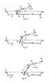
fig. 1 is a partial cross section of a container according
to a first form of embodiment that is not part of the invention; -
fig. 2 is a plane view of the container infig. 1 , in a closed condition; -
fig. 3 is a plane view of the container infig. 1 , in an open condition; -
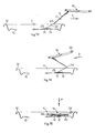
figs. 4 to 15 are schematic cross sections of part of the container infig. 1 , which represent, in sequence, the steps for opening the closing element of the container; -
fig. 16 is a plane view of a variant of the container infig. 1 , that is not part of the invention in a closed condition; -
fig. 17 is a cross section of the container infig. 16 ; -
fig. 18 is a plane view of a lid of a container according to the present invention, in a closed condition; -
fig. 19 is a cross section from XIX to XIX offig. 18 ; -
fig. 20 is a plane view of the lid infig. 18 in a partly open condition; -
fig. 21 is a cross section from XXI to XXI offig. 20 ; -
fig. 22 is a plane view of the lid infig. 18 in a completely open condition; -
fig. 23 is a cross section from XXIII to XXIII offig. 22 ; -
fig. 24 is a plane view of some details of the container infig. 18 ; -
fig. 25 is a plane view of a lid of a container according to the present invention, according to a form of embodiment that is not part of the invention. - The subject matter corresponding to the first (
figs. 1-17 ) and third (fig. 25 ) embodiments are not part of the present invention. - With reference to
fig. 1 , acontainer 10 is represented by a can to contain a substance, such as for example a drink. Thecontainer 10 is made for example of aluminum, steel or alloys thereof, it is substantially cylindrical in shape and has an externallateral surface 40, anupper wall 11, which functions as a lid, and a bottom, of any type, known, and not shown in the drawings. - The
upper wall 11 is substantially circular in shape (figs. 2 and 3 ), concentric with respect to a central axis Y (figs. 1 to 15 ). Furthermore, theupper wall 11 has aperipheral rib 12 of annular shape, which delimits acentral zone 36 having a determinate radius A. - A
groove 38 is made on theupper wall 11 and, in the form of embodiment shown infigs. 1 to 15 , is defined by a circular closed line, concentric to theperipheral rib 12. - On the
central zone 36, a line of weakening 13 (fig. 2 ) is made, in a known manner, closed on itself, having a locally reduced or variable cross section, which delimits a closing element or stopper 14 in the shape of a tongue. Thestopper 14 normally closes acorresponding aperture 15 through which the substance can be removed from thecontainer 10. In particular, when thecontainer 10 is in a closed condition (fig. 2 ), thestopper 14 closes theaperture 15 completely and hermetically, whereas in an open condition it is raised and at least partly removed from the aperture 15 (fig. 3 ), although it remains solid with the remaining part of thecontainer 10. - The
stopper 14, as will be shown in more detail hereafter in the description, is solidly attached to alever 16 which, in the closed condition (fig. 2 ), at least partly overlaps thestopper 14. - The
lever 16 is driven manually, by means of a gripping end thereof, orring 32, to separate thestopper 14 from the remaining part of theupper wall 11, along the line of weakening 13. - The
ring 32 faces towards the inside of theupper wall 11, that is, towards thecentral zone 36, to make it easier to grip and drive thelever 16. Advantageously, in the closed condition thering 32 is substantially in correspondence with the central axis Y passing through the center of thecentral zone 36. - The
lever 16 is pivoted on one end 34 (fig. 1 ) opposite thering 32, that is, disposed substantially in correspondence with theperipheral rib 12. In particular, in the closed condition (fig. 2 ) theend 34 is outside the line of weakening 13 and rests in direct contact on aridge 35, facing upwards and made on theupper wall 11. Theridge 35 is substantially U-shaped, that is, with two rectilinear segments, opposite and parallel, connected by a curved segment, nearer theperipheral rib 12. - The curved segment of the
ridge 35 is at least partly comprised between theperipheral rib 12 and the line of weakening 13 and at least partly surrounds both thestopper 14 and the correspondingaperture 15, and also thelever 16. In particular, theend 34 of thelever 16 rests on the curved segment of the ridge 35 (fig. 1 ). - Moreover, the
lever 16 comprises an intermediate zone 39 (fig. 1 ), comprised between itsends flexible tongue 17 is attached, which is in turn connected to thestopper 14. - The
intermediate zone 39 is advantageously nearer theend 34, which functions as a fulcrum and, in particular is attached for example by means of welding to anend 18 of thetongue 17. - In the closed condition (
fig. 2 ), theend 18 of thetongue 17 is disposed in substantial proximity with theperipheral rib 12. - The
tongue 17 is normally positioned on theupper wall 11, interposed between thelever 16 and the stopper 14 (fig. 1 ). In particular, thetongue 17 has an extension such as to cover thewhole stopper 14 and is attached to it by means of a rivet 20 (fig. 1 ). - Moreover, the
tongue 17 has an end 19 (fig. 2 ), normally positioned in correspondence with thecentral zone 36, by means of which it is solidly attached to theupper wall 11, for example with arivet 37. - In this case, the
tongue 17 is also provided with five lines of predetermined bending, respectively 21, 22, 23, 24 and 25, which delimit relative portions thereof 26, 27, 28, 29, 30 and 31. - The first line of bending 21 delimits the portion 26 (
fig. 9 ), in substantial correspondence with theend 18 of thetongue 17, which functions as a connection element with thelever 16. In this way, since thetongue 17 is in turn solidly attached to thestopper 14, a connection is achieved between thestopper 14 and thelever 16. - The second line of bending 22 defines the portion 27 (
figs. 8 and 9 ), which is adjacent to theportion 26 and is attached to thestopper 14 by means of therivet 20. - The third line of bending 23 defines the portion 28 (
fig. 11 ), which is disposed adjacent to theportion 27, while the fourth line of bending 24 defines the portion 29 (fig. 12 ), which is disposed adjacent to theportion 28. - Finally, the fifth line of bending defines the portion 31 (
figs. 13 and 14 ), in correspondence with theend 19 of thetongue 17 and in a position opposite to theportion 26. In particular theportion 31 is attached to theupper wall 11 by means of therivet 37. - By rotating the
lever 16 around itsend 34, theend 32 is distanced from thewall 11 and thestopper 14 is partly detached from theupper wall 11, so that theaperture 15 begins to open. This happens because the line of weakening 13 yields, if subjected to a predetermined lifting force. - Since the connection zones between the
lever 16 and thetongue 17 and between thetongue 17 and thestopper 14 are different and in close proximity, thelever 16, which acts on thestopper 14, defines an extremely favorable arm that allows, with limited force, to apply a high angular moment. - Furthermore, the force of the
lever 16 is applied at a point of application in close proximity with the line of weakening 13 and with a rotation towards the outside of thecontainer 10. What is more, the resistant section of the line of weakening 13 on which thelever 16 acts is much smaller than the remaining part of the line ofweakening 13. Therefore, from the above, it is clear that the force necessary to lift thestopper 14 along the line of weakening 13 is much less compared with containers with a hygienic stopper that are known in the state of the art. - A further distancing upwards of the
end 34 of thelever 16 allows to remove thestopper 14 completely from theupper wall 11 and to position theflexible tongue 17 in its bent configuration. - In the bent configuration (
fig. 15 ), theflexible tongue 17 is positioned above theupper wall 11 and at the side of theaperture 15, while itsportions wall 11 and overlapping each other. In the bent configuration, theportion 26 is in an upper position, immediately below thelever 16, while theportion 31 is below all theother portions upper wall 11. Consequently, in the bent configuration of theflexible tongue 17, theportions portion 26 and theportion 31, as can be clearly seen infigs. 14 and 15 . - The
rivet 20, cooperating with one edge of thelever 16, also selectively keeps theflexible tongue 17 in its bent configuration. - It is clear that the
stopper 14, since it is solid with thetongue 17, is also able to bend into relative portions, which are positioned one above the other, in correspondence with the intermediate lines of bending 22, 23 and 24 of thetongue 17. - As described above, in the bent configuration, the
portions lever 16 is positioned above them. In this way, thelever 16 does not protrude excessively from thecontainer 10, and neither thelever 16 nor thetongue 17, nor thestopper 14 are an impediment to the user who wants to remove the substance from thecontainer 10. - The
container 10 as described heretofore is used as follows. - Initially, the
container 10 is normally in its closed condition (figs. 2 and4 ). To open it, the user has to grip thering 32 of thelever 16 and rotate it in the direction of rotation indicated by the arrow R infigs. 5, 6 and 7 , around itsend 34. This causes a part of thestopper 14 to be detached from the remaining part of theupper wall 11, and also the consequent definition of a part of theaperture 15, in correspondence with theportion 27, and the bending of thestopper 14 and thetongue 17, along the line of bending 22. - The
stopper 14 is lifted upwards and therefore never enters into contact with the substance contained in thecontainer 10, guaranteeing that the optimum hygienic conditions under which the substance was inserted into thecontainer 10 are maintained. - Subsequently, the user pulls the
lever 16 with a tangential force, in the direction of the arrow F infigs. 8 to 13 , causing the further inclination beyond 90° of thestopper 14 and thetongue 17, in correspondence with the line of bending 22 (figs. 7 to 10 ) and, subsequently, causing thestopper 14 andtongue 17 to bend along the lines of bending 23 and 24 and to incline even further (figs. 11 and 12 ). In this way, thestopper 14, while remaining solid with theportions tongue 17, in turn attached to theupper wall 11, completely frees theaperture 15 and thecontainer 10 is put in its open condition (figs. 3 ,12 and13 ). - At this point, with a movement in the direction as indicated by the direction of the arrow G in
fig. 14 , theportions tongue 17, thestopper 14 and thelever 16 are made to overlap. Finally, as indicated by arrow P infig. 15 , theportions tongue 17, thestopper 14 and therelative lever 16 close concertina-wise. - Thanks to the lines of bending 21, 22, 23, 24 and 25, the
lever 16, thestopper 14 and theflexible tongue 17 are easily repositioned several times in the closed condition, allowing the user to close thecontainer 10 with thestopper 14 as desired and temporarily. - According to a variant, a
container 110 that is not part of the present invention, shown infigs. 16 and 17 , where the same reference numbers correspond to equivalent parts, comprises agroove 138, made on theupper wall 11, which instead of being closed like thegroove 38, is open, that is, interrupted in correspondence with thestopper 14 and theaperture 15. In this way the substance contained in thecontainer 110, once it has come out, is prevented from stagnating, partly, in thegroove 138, creating unhygienic conditions. - According to another variant, not shown in the drawings, the
lever 16 is provided with a gripping ring of double size with respect to thering 32, so as to be able to drive thelever 16 more easily with two fingers, instead of one, as normally happens. - In accordance with a form of embodiment of the present invention, shown in
figs. 18 to 24 , acontainer 210 has anupper wall 211 provided with aperipheral rib 212 of annular shape, which delimits acentral zone 236. - A
groove 238, analogous to thegroove 38, is made on theupper wall 211. - A line of weakening 213 is made on the
central zone 236, which is not closed on itself and which delimits a closing element orstopper 214, in the form of a tongue, always integral with the remaining part of thecentral part 236, even when it is in the open condition (figs. 22 and 23 ). - In particular, the stopper 214 (
fig. 24 ) comprises afirst part 214a substantially circular in shape, and asecond part 214b substantially rectangular in shape and contiguous to thefirst part 214a. Thestopper 214 normally closes acorresponding aperture 215 and is solidly attached to alever 216 which, in the closed condition (figs. 18 and 19 ), is at least partly overlapping therewith. - The
lever 216 is driven manually, by means of a gripping end thereof, orring 232, to separate thestopper 214 from the remaining part of thecentral zone 236 of theupper wall 211, along the line ofweakening 213. - The
lever 216 is pivoted at one end 234 (fig. 18 ) opposite thering 232, that is, disposed substantially in correspondence with theperipheral rib 212. - Moreover, the
lever 216 comprises an intermediate zone 239 (fig. 18 ), comprised between itsends flexible tongue 251 is made, which is in turn connected to thestopper 214 by means of arivet 250. - The
intermediate zone 239 is advantageously nearer theend 234, which functions as a fulcrum. - The
stopper 214 is removed as follows: firstly thering 232 of thelever 216 is lifted manually towards the outside of thecontainer 210, pivoting on itsfirst end 214, so that theintermediate zone 239 of thelever 216 partly detaches thestopper 214 from the remaining part of the central zone 236 (figs. 20 and 21 ), along the line ofweakening 213; then thering 232 is pulled back so as to lift thestopper 214 and continue to detach it along the line ofweakening 213, until theaperture 215 is completely open (figs. 22 and 23 ). -
Fig. 25 shows a third form of embodiment of acontainer 310 that is not part of the present invention, which comprises anupper wall 311 provided with aperipheral rib 312 of annular shape, which delimits acentral zone 336. - A
groove 338, analogous to thegrooves upper wall 311. - A line of weakening 313 is made on the
central zone 336, which (like the line 213) is not closed on itself and which delimits a closing element orstopper 314, in the form of a tongue, always integral with the remaining part of thecentral part 336, even when it is in the open condition. - In particular, the
stopper 314 has a substantially rectangular shape, it normally closes a corresponding aperture 315 and is solidly attached to alever 316 which, in the closed condition, is at least partly overlapping therewith. - The
lever 316 is driven manually, by means of a gripping end thereof, orring 332, to separate thestopper 314 from the remaining part of thecentral zone 336 of theupper wall 311, along the line ofweakening 313. - The
lever 316 is pivoted at oneend 334 opposite thering 332, that is, disposed substantially in correspondence with the center of thecentral zone 336. - Moreover, the
lever 316 comprises anintermediate zone 339 comprised between itsends flexible tongue 351 is made, which is in turn connected to thestopper 314 by means of arivet 350. - The
stopper 314 is removed as follows: firstly thering 332 of thelever 316 is lifted manually, bending it towards the center of theupper wall 311, pivoting on itsfirst end 314, so that theintermediate zone 339 of thelever 316 partly detaches thestopper 314 from the remaining part of thecentral zone 336, along the line ofweakening 313; then thering 332 is further pulled back and on the same side so as to lift thestopper 314 and continue to detach it along the line ofweakening 313, until the aperture 315 is completely open. - It is clear that modifications and/or additions of parts may be made to the
containers 210, as described heretofore, without departing from the scope of the present invention.
Claims (11)
- Container for a substance, in particular a drink, comprising at least: an upper wall (211) functioning as a lid, having a peripheral rib (212) delimiting a central zone (236) having a substantially circular shape with a determinate radius (A), concentric with respect to a central axis (Y), which is solid with said peripheral rib (212) and on which an interrupted line of weakening (213) is made, which defines a pull-open closing element (214) always integral with the remaining part of the central part (236) and provided with a front terminal part disposed next to said peripheral rib (212), which closing element (214) functions as a removable stopper to a relative aperture (215) for said substance to pass through, made in said central zone (236); and a lever (216), having at least a part connected to said closing element (214) and which can be driven so as to remove, at least partly, said closing element (214) from the remaining part of said central zone (236), detaching it along said line of weakening (213) and thus putting said aperture (215) in communication with the outside, said line of weakening (213) being interrupted at one end of said closing element (214) which is on the opposite side of said lever (216) with respect to said central axis (Y), so that said closing element (214) has an edge solid with the remaining part of said central zone (236), characterized in that said lever (216) comprises:- a first end (234) having a central part functioning as a fulcrum disposed in correspondence with said peripheral rib (212), outside said closing element (214) defined by said line of weakening (213) and in front of said front terminal part, said fulcrum being able to determine the lifting of said closing element (214) by drawing;- a second end (232) disposed in substantial correspondence with said central zone (236), opposite said first end (234) and functioning as a gripping, lifting and drawing element, the distance between said first end (234) and said second end (232) being a little less than the length of said radius (A);- and an intermediate zone (239) between said first end (234) and said second end (232), by means of which said lever (216) is connected to said closing element (214), said intermediate zone (239) of said lever (216) comprising a flexible tongue (251) mechanically connected to said closing element (214) in the front terminal part thereof, to lift and detach said front terminal part of said closing element (214) from the remaining part of the central zone (236), without any part of the closing element (214) coming into contact with the substance contained inside the container.
- Container as in claim 1, characterized in that said lever (216) is substantially parallel to said radius (A).
- Container as in claim 2, characterized in that said second end (232) is disposed near said central axis (Y).
- Container as in claim 2 or 3, characterized in that said closing element (214) defined by said line of weakening (213) comprises a tongue having a first part (214a) substantially circular in shape and a second part (214b) substantially rectangular in shape and contiguous with said first part (214a), said first part comprising said front terminal part.
- Container as in claim 4, characterized in that said lever (216) is disposed above said first part (214a) of said closing element (214).
- Container as in claim 4 or 5, characterized in that said line of weakening (213) is interrupted at the end of said second part (214b) which is on the opposite side of said lever (216) with respect to said central axis (Y), so that said closing element (214) has an edge solid with the remaining part of said central zone (236).
- Container as in claim 4, 5 or 6, characterized in that said flexible tongue (251) is mechanically connected to said front terminal part of said closing element (214) by means of a mechanical connection mean (250).
- Container as in claim 7, characterized in that said mechanical connection mean (250) is a rivet or a welding point.
- Container as in any claim hereinbefore, characterized in that said lever (216) is able to be rotated towards the outside of said peripheral rib (212).
- Lid for a container able to contain a substance, in particular a drink, comprising: a peripheral rib (212) delimiting a central zone (236) having a substantially circular shape with a determinate radius (A), concentric with respect to a central axis (Y), which is solid with said peripheral rib (212) and on which an interrupted line of weakening (213) is made, which defines a pull-open closing element (214) always integral with the remaining part of the central part (236) and provided with a front terminal part disposed next to said peripheral rib (212), which closing element (214) functions as a removable stopper to a relative aperture (215) for said substance to pass through, made in said central zone (236); and a lever (216), having at least a part connected to said closing element (214) and which can be driven so as to remove, at least partly, said closing element (214) from the remaining part of said central zone (236), detaching it along said line of weakening (213) and thus putting said aperture (215) in communication with the outside, said line of weakening (213) being interrupted at one end of said closing element (214) which is on the opposite side of said lever (216) with respect to said central axis (Y), so that said closing element (214) has an edge solid with the remaining part of said central zone (236), characterized in that said lever (216) comprises:- a first end (234) having a central part functioning as a fulcrum disposed in correspondence with said peripheral rib (212), outside said closing element (214) defined by said line of weakening (213) and in front of said front terminal part, said fulcrum being able to determine the lifting of said closing element (214) by drawing;- a second end (232) disposed in substantial correspondence with said central zone (236), opposite said first end (234) and functioning as a gripping, lifting and drawing element, the distance between said first end (234) and said second end (232) being a little less than the length of said radius (A);- and an intermediate zone (239) between said first end (234) and said second end (232), by means of which said lever (216) is connected to said closing element (214), said intermediate zone (239) of said lever (216) comprising a flexible tongue (251) mechanically connected to said closing element (214) in the front terminal part thereof, to lift and detach said front terminal part of said closing element (214) from the remaining part of the central zone (236), without any part of the closing element (214) coming into contact with the substance contained inside the container and keeping the closing element (214) always solid with the remaining part of the central zone (236).
- Method to open a closing element (214) of a container able to contain a substance, in particular a drink, wherein said container comprises an upper wall (211) functioning as a lid, having a peripheral rib (212) delimiting a central zone (236) having a substantially circular shape with a determinate radius (A), concentric with respect to a central axis (Y), which is solid with said peripheral rib (212) and on which an interrupted line of weakening (213) is made, which defines said pull-open closing element (214) always integral with the remaining part of the central part (236) and provided with a front terminal part disposed next to said peripheral rib (212), which closing element (214) functions as a removable stopper to a relative aperture (215) for said substance to pass through, made in said central zone (236); and a lever (216), having at least a part connected to said closing element (214) and which can be driven so as to remove, at least partly, said closing element (214) from the remaining part of said central zone (236) by drawing, detaching it along said line of weakening (213), said line of weakening (213) being interrupted at one end of said closing element (214) which is on the opposite side of said lever (216) with respect to said central axis (Y), so that said closing element (214) has an edge solid with the remaining part of said central zone (236); wherein said lever (216) comprises:- a first end (234) having a central part having a fulcrum disposed in correspondence with said peripheral rib (212), outside said closing element (214) defined by said line of weakening (213) and in front of said front terminal part, said fulcrum being able to determine the lifting of said closing element (214) by drawing, without the latter going inside the container;- a second end (232) disposed in substantial correspondence with said central zone (236), opposite said first end (234) and functioning as a gripping, lifting and drawing element, the distance between said first end (234) and said second end (232) being a little less than the length of said radius (A);- and an intermediate zone (239) between said first end (234) and said second end (232), by means of which said lever (216) is connected to said closing element (214), said intermediate zone (239) of said lever (216) comprising a flexible tongue (251) mechanically connected to said closing element (214) in the front terminal part thereof, said method comprising the following steps:- lifting said second end (232) of said lever (216), rotating it toward the outside of said peripheral rib (212), pivoting on said first end (234) thereof so that said flexible tongue (251) of said intermediate zone (239) lifts and detaches the front terminal part of said closing element (214) from the remaining part of the central zone (236), without any part of the closing element (214) coming into contact with the substance contained inside the container and keeping the closing element (214) always solid with the remaining part of the central zone (236); and- pulling backwards said second end of said lever (216) so as to lift said closing element (214) and continue to detach it along said line of weakening (213), keeping the closing element (214) always solid with the remaining part of the central zone (236), until said aperture (215) is opened.
Priority Applications (3)
| Application Number | Priority Date | Filing Date | Title |
|---|---|---|---|
| PL08750201T PL2200903T3 (en) | 2007-09-07 | 2008-05-08 | Container for a substance, in particular a drink, with a tear-open closing element |
| SI200830648T SI2200903T1 (en) | 2007-09-07 | 2008-05-08 | Container for a substance, in particular a drink, with a tear-open closing element |
| CY20121100505T CY1113041T1 (en) | 2007-09-07 | 2012-06-06 | HOLDER FOR A SUBSTANCE, SPECIFICALLY A DRINK, WITH AN EXPLOSIVE CLOSING ITEM |
Applications Claiming Priority (2)
| Application Number | Priority Date | Filing Date | Title |
|---|---|---|---|
| IT000159A ITUD20070159A1 (en) | 2007-09-07 | 2007-09-07 | CONTAINER FOR A SUBSTANCE, IN PARTICULAR A BEVERAGE, WITH OPENING CLOSING ELEMENT |
| PCT/EP2008/055707 WO2009030526A1 (en) | 2007-09-07 | 2008-05-08 | Container for a substance, in particular a drink, with a tear-open closing element |
Publications (2)
| Publication Number | Publication Date |
|---|---|
| EP2200903A1 EP2200903A1 (en) | 2010-06-30 |
| EP2200903B1 true EP2200903B1 (en) | 2012-03-07 |
Family
ID=39673461
Family Applications (1)
| Application Number | Title | Priority Date | Filing Date |
|---|---|---|---|
| EP08750201A Active EP2200903B1 (en) | 2007-09-07 | 2008-05-08 | Container for a substance, in particular a drink, with a tear-open closing element |
Country Status (24)
| Country | Link |
|---|---|
| US (1) | US8336727B2 (en) |
| EP (1) | EP2200903B1 (en) |
| JP (1) | JP5430010B2 (en) |
| CN (1) | CN101801800B (en) |
| AT (1) | ATE548277T1 (en) |
| AU (1) | AU2008295021B2 (en) |
| BR (1) | BRPI0816397B1 (en) |
| CA (1) | CA2698479C (en) |
| CY (1) | CY1113041T1 (en) |
| DK (1) | DK2200903T3 (en) |
| EG (1) | EG26035A (en) |
| ES (1) | ES2383926T3 (en) |
| HK (1) | HK1146925A1 (en) |
| IL (1) | IL204315A (en) |
| IT (1) | ITUD20070159A1 (en) |
| MA (1) | MA31825B1 (en) |
| MX (1) | MX2010002597A (en) |
| MY (1) | MY161989A (en) |
| PL (1) | PL2200903T3 (en) |
| PT (1) | PT2200903E (en) |
| RS (1) | RS52322B (en) |
| RU (1) | RU2482037C2 (en) |
| SI (1) | SI2200903T1 (en) |
| WO (1) | WO2009030526A1 (en) |
Families Citing this family (12)
| Publication number | Priority date | Publication date | Assignee | Title |
|---|---|---|---|---|
| IT1394648B1 (en) | 2009-07-03 | 2012-07-05 | Internat Patents And Brands Corp | COVER FOR CONTAINERS OF SUBSTANCES AND CONTAINER OF SUBSTANCES SO FULLY EQUIPPED |
| US10017295B2 (en) | 2010-08-06 | 2018-07-10 | Ball Corporation | Container end closure with optional secondary vent opening |
| US20130284742A1 (en) * | 2012-04-25 | 2013-10-31 | Alan Jung | Easy Open Lid |
| ES2647932T3 (en) * | 2012-05-04 | 2017-12-27 | Ball Corporation | Metal end closure with tear panel that has improved rigidity |
| US9254945B2 (en) | 2012-08-24 | 2016-02-09 | Stolle Machinery Company, Llc | Easy pour spout |
| CN105102332B (en) | 2013-03-15 | 2016-12-28 | 鲍尔公司 | There is the end cap of the secondary blow vent that draw ring activates |
| MX2016008938A (en) | 2014-01-08 | 2017-02-02 | Int Patents And Brands Corp | Lid for containers of substances and container of substances comprising said lid. |
| US9714115B2 (en) | 2014-07-30 | 2017-07-25 | Ball Corporation | Vented container end closure |
| CA3044700A1 (en) | 2016-11-25 | 2018-05-31 | Joao Marques Fernandes | Constructive arrangement for the opening of a beverage can |
| ES2883369T3 (en) * | 2016-12-01 | 2021-12-07 | Fernandes Joao Marques | Constructive arrangement for opening a beverage can |
| JP6942285B1 (en) * | 2020-01-10 | 2021-09-29 | 株式会社Ky7 | Lid |
| MX2023000666A (en) | 2020-07-13 | 2023-05-03 | Oc Bev Ltd | Lid for containers of substances, and container of substances comprising said lid. |
Family Cites Families (15)
| Publication number | Priority date | Publication date | Assignee | Title |
|---|---|---|---|---|
| US3478918A (en) * | 1968-08-14 | 1969-11-18 | American Can Co | Full open end closure |
| BE790950A (en) * | 1971-11-03 | 1973-03-01 | Nat Can Corp | FULLY OPENING CONTAINER BOTTOM CLOSURE |
| US3730380A (en) * | 1972-01-17 | 1973-05-01 | Fraze Ermal C | Can end with inseparable tear strip and latch means for holding tear strip against can wall |
| US3731836A (en) * | 1972-03-17 | 1973-05-08 | Fraze Ermal C | Container wall with connector for retaining the tab and tear portion on the container wall |
| US3877606A (en) * | 1972-04-20 | 1975-04-15 | Fraze Ermal C | Easy opening container wall with retained tear strip |
| US3795340A (en) * | 1972-08-04 | 1974-03-05 | Continental Can Co | Tab mounting arrangement for easy opening can end |
| US4189060A (en) * | 1978-10-05 | 1980-02-19 | Minnesota Mining And Manufacturing Company | Retention means for container closure assembly |
| US4203528A (en) * | 1979-04-30 | 1980-05-20 | The Continental Group, Inc. | Self-storing pull strip for easy opening containers |
| US4417668A (en) * | 1981-09-03 | 1983-11-29 | Stolle Research And Development Corporation | Easy open can end with pull tab having retained tear strip with stress relief means |
| US4687116A (en) * | 1986-09-10 | 1987-08-18 | Sun Coast Plastics, Inc. | Easy open container end closure |
| FR2675467B1 (en) * | 1991-04-16 | 1995-02-17 | Lorraine Laminage | PARTIAL OPENING COVER FOR METAL BOX. |
| US5145086A (en) * | 1991-05-17 | 1992-09-08 | Krause Arthur A | Captive tear tab with protective means for container opening |
| IT1280461B1 (en) * | 1995-09-11 | 1998-01-20 | Cesare Mongarli | CONTAINER, PARTICULARLY FOR DRINKS. |
| KR100302638B1 (en) * | 1999-07-05 | 2001-11-07 | 조성호 | Can lid with opening means providing enhanced opening function and sanitariness |
| CN2436439Y (en) * | 2000-06-13 | 2001-06-27 | 杜依民 | Environment protection pop-top can |
-
2007
- 2007-09-07 IT IT000159A patent/ITUD20070159A1/en unknown
-
2008
- 2008-05-08 DK DK08750201.9T patent/DK2200903T3/en active
- 2008-05-08 BR BRPI0816397-9A patent/BRPI0816397B1/en active IP Right Grant
- 2008-05-08 WO PCT/EP2008/055707 patent/WO2009030526A1/en active Application Filing
- 2008-05-08 CA CA2698479A patent/CA2698479C/en active Active
- 2008-05-08 CN CN2008801060661A patent/CN101801800B/en active Active
- 2008-05-08 AU AU2008295021A patent/AU2008295021B2/en active Active
- 2008-05-08 RS RS20120239A patent/RS52322B/en unknown
- 2008-05-08 RU RU2010112488/12A patent/RU2482037C2/en active
- 2008-05-08 MX MX2010002597A patent/MX2010002597A/en active IP Right Grant
- 2008-05-08 PL PL08750201T patent/PL2200903T3/en unknown
- 2008-05-08 JP JP2010523446A patent/JP5430010B2/en active Active
- 2008-05-08 ES ES08750201T patent/ES2383926T3/en active Active
- 2008-05-08 SI SI200830648T patent/SI2200903T1/en unknown
- 2008-05-08 EP EP08750201A patent/EP2200903B1/en active Active
- 2008-05-08 AT AT08750201T patent/ATE548277T1/en active
- 2008-05-08 US US12/677,016 patent/US8336727B2/en active Active
- 2008-05-08 MY MYPI2010000954A patent/MY161989A/en unknown
- 2008-05-08 PT PT08750201T patent/PT2200903E/en unknown
-
2010
- 2010-03-04 IL IL204315A patent/IL204315A/en active IP Right Grant
- 2010-03-07 EG EG2010030366A patent/EG26035A/en active
- 2010-04-01 MA MA32734A patent/MA31825B1/en unknown
-
2011
- 2011-02-01 HK HK11101059.3A patent/HK1146925A1/en unknown
-
2012
- 2012-06-06 CY CY20121100505T patent/CY1113041T1/en unknown
Also Published As
| Publication number | Publication date |
|---|---|
| CA2698479C (en) | 2015-04-14 |
| AU2008295021A2 (en) | 2010-05-06 |
| SI2200903T1 (en) | 2012-07-31 |
| EG26035A (en) | 2012-12-19 |
| ITUD20070159A1 (en) | 2007-12-07 |
| HK1146925A1 (en) | 2011-07-22 |
| RU2482037C2 (en) | 2013-05-20 |
| PT2200903E (en) | 2012-06-18 |
| MX2010002597A (en) | 2010-06-01 |
| PL2200903T3 (en) | 2012-08-31 |
| BRPI0816397B1 (en) | 2019-06-18 |
| ATE548277T1 (en) | 2012-03-15 |
| AU2008295021B2 (en) | 2013-03-28 |
| RU2010112488A (en) | 2011-10-20 |
| CY1113041T1 (en) | 2016-04-13 |
| CA2698479A1 (en) | 2009-03-12 |
| DK2200903T3 (en) | 2012-07-02 |
| JP5430010B2 (en) | 2014-02-26 |
| MY161989A (en) | 2017-05-31 |
| BRPI0816397A2 (en) | 2018-07-31 |
| RS52322B (en) | 2012-12-31 |
| EP2200903A1 (en) | 2010-06-30 |
| CN101801800A (en) | 2010-08-11 |
| IL204315A (en) | 2014-06-30 |
| US8336727B2 (en) | 2012-12-25 |
| CN101801800B (en) | 2012-07-11 |
| US20100258562A1 (en) | 2010-10-14 |
| MA31825B1 (en) | 2010-11-01 |
| ES2383926T3 (en) | 2012-06-27 |
| AU2008295021A1 (en) | 2009-03-12 |
| WO2009030526A1 (en) | 2009-03-12 |
| JP2010537905A (en) | 2010-12-09 |
Similar Documents
| Publication | Publication Date | Title |
|---|---|---|
| EP2200903B1 (en) | Container for a substance, in particular a drink, with a tear-open closing element | |
| US3977561A (en) | Can end with nondetachable tear tab and opening ring | |
| US3225957A (en) | Metal end closure | |
| US8870012B2 (en) | Flip-up pop-top can lid | |
| CA2766969C (en) | Lid for containers of substances and container of substances thus equipped | |
| AU2001273746B2 (en) | Can lid | |
| EP0918038B1 (en) | Multipurpose tool for opening containers like bottles and cans | |
| US10773854B2 (en) | Resealable beverage can lid | |
| EP2621820A1 (en) | Lid for beverage can | |
| EP0221913A1 (en) | Easy-open closure | |
| EP3912923A1 (en) | Closure lid for an "easy-open" container | |
| EP0090809B1 (en) | Closure for containers | |
| JP2000190963A (en) | Easy-to-open can-lid | |
| US4624387A (en) | Easy-to-open lid of a container | |
| NL8302045A (en) | OPEN COVER LID, PARTICULARLY IN SHEET STEEL, FOR TINS. | |
| JPH07172436A (en) | Easily openable can cap | |
| EP2493775B1 (en) | A lid for containers such as cans and the like | |
| CA2023588C (en) | Can top | |
| WO2020139429A1 (en) | Resealable beverage can lid | |
| WO1997027117A1 (en) | Reclosable drink can | |
| JPH04114858A (en) | Opening device for can container |
Legal Events
| Date | Code | Title | Description |
|---|---|---|---|
| PUAI | Public reference made under article 153(3) epc to a published international application that has entered the european phase |
Free format text: ORIGINAL CODE: 0009012 |
|
| 17P | Request for examination filed |
Effective date: 20100406 |
|
| AK | Designated contracting states |
Kind code of ref document: A1 Designated state(s): AT BE BG CH CY CZ DE DK EE ES FI FR GB GR HR HU IE IS IT LI LT LU LV MC MT NL NO PL PT RO SE SI SK TR |
|
| AX | Request for extension of the european patent |
Extension state: AL BA MK RS |
|
| 17Q | First examination report despatched |
Effective date: 20101007 |
|
| R17C | First examination report despatched (corrected) |
Effective date: 20101007 |
|
| GRAP | Despatch of communication of intention to grant a patent |
Free format text: ORIGINAL CODE: EPIDOSNIGR1 |
|
| RIN1 | Information on inventor provided before grant (corrected) |
Inventor name: CAMURRI, EDMONDO Inventor name: LINDEN, PAOLO |
|
| GRAS | Grant fee paid |
Free format text: ORIGINAL CODE: EPIDOSNIGR3 |
|
| GRAA | (expected) grant |
Free format text: ORIGINAL CODE: 0009210 |
|
| AK | Designated contracting states |
Kind code of ref document: B1 Designated state(s): AT BE BG CH CY CZ DE DK EE ES FI FR GB GR HR HU IE IS IT LI LT LU LV MC MT NL NO PL PT RO SE SI SK TR |
|
| AX | Request for extension of the european patent |
Extension state: AL BA MK RS |
|
| REG | Reference to a national code |
Ref country code: GB Ref legal event code: FG4D |
|
| REG | Reference to a national code |
Ref country code: AT Ref legal event code: REF Ref document number: 548277 Country of ref document: AT Kind code of ref document: T Effective date: 20120315 Ref country code: CH Ref legal event code: EP |
|
| REG | Reference to a national code |
Ref country code: IE Ref legal event code: FG4D |
|
| REG | Reference to a national code |
Ref country code: DE Ref legal event code: R096 Ref document number: 602008013964 Country of ref document: DE Effective date: 20120503 |
|
| REG | Reference to a national code |
Ref country code: RO Ref legal event code: EPE |
|
| REG | Reference to a national code |
Ref country code: CH Ref legal event code: NV Representative=s name: MICHELI & CIE SA |
|
| REG | Reference to a national code |
Ref country code: PT Ref legal event code: SC4A Free format text: AVAILABILITY OF NATIONAL TRANSLATION Effective date: 20120606 |
|
| REG | Reference to a national code |
Ref country code: SE Ref legal event code: TRGR |
|
| REG | Reference to a national code |
Ref country code: NL Ref legal event code: T3 |
|
| REG | Reference to a national code |
Ref country code: ES Ref legal event code: FG2A Ref document number: 2383926 Country of ref document: ES Kind code of ref document: T3 Effective date: 20120627 |
|
| REG | Reference to a national code |
Ref country code: DK Ref legal event code: T3 |
|
| REG | Reference to a national code |
Ref country code: NO Ref legal event code: T2 Effective date: 20120307 |
|
| PG25 | Lapsed in a contracting state [announced via postgrant information from national office to epo] |
Ref country code: HR Free format text: LAPSE BECAUSE OF FAILURE TO SUBMIT A TRANSLATION OF THE DESCRIPTION OR TO PAY THE FEE WITHIN THE PRESCRIBED TIME-LIMIT Effective date: 20120307 Ref country code: LT Free format text: LAPSE BECAUSE OF FAILURE TO SUBMIT A TRANSLATION OF THE DESCRIPTION OR TO PAY THE FEE WITHIN THE PRESCRIBED TIME-LIMIT Effective date: 20120307 |
|
| LTIE | Lt: invalidation of european patent or patent extension |
Effective date: 20120307 |
|
| PG25 | Lapsed in a contracting state [announced via postgrant information from national office to epo] |
Ref country code: LV Free format text: LAPSE BECAUSE OF FAILURE TO SUBMIT A TRANSLATION OF THE DESCRIPTION OR TO PAY THE FEE WITHIN THE PRESCRIBED TIME-LIMIT Effective date: 20120307 |
|
| REG | Reference to a national code |
Ref country code: PL Ref legal event code: T3 |
|
| REG | Reference to a national code |
Ref country code: GR Ref legal event code: EP Ref document number: 20120401293 Country of ref document: GR Effective date: 20120713 Ref country code: SK Ref legal event code: T3 Ref document number: E 11969 Country of ref document: SK |
|
| PG25 | Lapsed in a contracting state [announced via postgrant information from national office to epo] |
Ref country code: EE Free format text: LAPSE BECAUSE OF FAILURE TO SUBMIT A TRANSLATION OF THE DESCRIPTION OR TO PAY THE FEE WITHIN THE PRESCRIBED TIME-LIMIT Effective date: 20120307 Ref country code: IS Free format text: LAPSE BECAUSE OF FAILURE TO SUBMIT A TRANSLATION OF THE DESCRIPTION OR TO PAY THE FEE WITHIN THE PRESCRIBED TIME-LIMIT Effective date: 20120707 |
|
| REG | Reference to a national code |
Ref country code: HU Ref legal event code: AG4A Ref document number: E014364 Country of ref document: HU |
|
| PG25 | Lapsed in a contracting state [announced via postgrant information from national office to epo] |
Ref country code: MC Free format text: LAPSE BECAUSE OF NON-PAYMENT OF DUE FEES Effective date: 20120531 |
|
| PLBE | No opposition filed within time limit |
Free format text: ORIGINAL CODE: 0009261 |
|
| STAA | Information on the status of an ep patent application or granted ep patent |
Free format text: STATUS: NO OPPOSITION FILED WITHIN TIME LIMIT |
|
| 26N | No opposition filed |
Effective date: 20121210 |
|
| REG | Reference to a national code |
Ref country code: DE Ref legal event code: R097 Ref document number: 602008013964 Country of ref document: DE Effective date: 20121210 |
|
| PG25 | Lapsed in a contracting state [announced via postgrant information from national office to epo] |
Ref country code: BG Free format text: LAPSE BECAUSE OF NON-PAYMENT OF DUE FEES Effective date: 20121231 |
|
| PG25 | Lapsed in a contracting state [announced via postgrant information from national office to epo] |
Ref country code: LU Free format text: LAPSE BECAUSE OF NON-PAYMENT OF DUE FEES Effective date: 20120508 |
|
| REG | Reference to a national code |
Ref country code: FR Ref legal event code: PLFP Year of fee payment: 9 |
|
| REG | Reference to a national code |
Ref country code: FR Ref legal event code: PLFP Year of fee payment: 10 |
|
| REG | Reference to a national code |
Ref country code: FR Ref legal event code: PLFP Year of fee payment: 11 |
|
| PGFP | Annual fee paid to national office [announced via postgrant information from national office to epo] |
Ref country code: MT Payment date: 20220202 Year of fee payment: 15 |
|
| PGFP | Annual fee paid to national office [announced via postgrant information from national office to epo] |
Ref country code: CY Payment date: 20220214 Year of fee payment: 15 |
|
| PGFP | Annual fee paid to national office [announced via postgrant information from national office to epo] |
Ref country code: SI Payment date: 20220421 Year of fee payment: 15 |
|
| P01 | Opt-out of the competence of the unified patent court (upc) registered |
Effective date: 20230517 |
|
| PGFP | Annual fee paid to national office [announced via postgrant information from national office to epo] |
Ref country code: RO Payment date: 20230508 Year of fee payment: 16 Ref country code: PT Payment date: 20230504 Year of fee payment: 16 Ref country code: NO Payment date: 20230526 Year of fee payment: 16 Ref country code: NL Payment date: 20230510 Year of fee payment: 16 Ref country code: IT Payment date: 20230504 Year of fee payment: 16 Ref country code: IE Payment date: 20230529 Year of fee payment: 16 Ref country code: FR Payment date: 20230508 Year of fee payment: 16 Ref country code: ES Payment date: 20230609 Year of fee payment: 16 Ref country code: DK Payment date: 20230509 Year of fee payment: 16 Ref country code: DE Payment date: 20230516 Year of fee payment: 16 Ref country code: CZ Payment date: 20230509 Year of fee payment: 16 Ref country code: CH Payment date: 20230602 Year of fee payment: 16 Ref country code: BG Payment date: 20230525 Year of fee payment: 16 |
|
| PGFP | Annual fee paid to national office [announced via postgrant information from national office to epo] |
Ref country code: TR Payment date: 20230504 Year of fee payment: 16 Ref country code: SK Payment date: 20230509 Year of fee payment: 16 Ref country code: SE Payment date: 20230512 Year of fee payment: 16 Ref country code: PL Payment date: 20230504 Year of fee payment: 16 Ref country code: HU Payment date: 20230510 Year of fee payment: 16 Ref country code: GR Payment date: 20230531 Year of fee payment: 16 Ref country code: FI Payment date: 20230526 Year of fee payment: 16 Ref country code: AT Payment date: 20230526 Year of fee payment: 16 |
|
| PGFP | Annual fee paid to national office [announced via postgrant information from national office to epo] |
Ref country code: BE Payment date: 20230510 Year of fee payment: 16 |
|
| PGFP | Annual fee paid to national office [announced via postgrant information from national office to epo] |
Ref country code: GB Payment date: 20230509 Year of fee payment: 16 |
|
| PG25 | Lapsed in a contracting state [announced via postgrant information from national office to epo] |
Ref country code: SI Free format text: LAPSE BECAUSE OF NON-PAYMENT OF DUE FEES Effective date: 20230509 Ref country code: CY Free format text: LAPSE BECAUSE OF NON-PAYMENT OF DUE FEES Effective date: 20230508 |
|
| REG | Reference to a national code |
Ref country code: SI Ref legal event code: KO00 Effective date: 20240222 |