EP2200832B1 - Pompe d'évacuation pour système d'alimentation en encre - Google Patents
Pompe d'évacuation pour système d'alimentation en encre Download PDFInfo
- Publication number
- EP2200832B1 EP2200832B1 EP08838199A EP08838199A EP2200832B1 EP 2200832 B1 EP2200832 B1 EP 2200832B1 EP 08838199 A EP08838199 A EP 08838199A EP 08838199 A EP08838199 A EP 08838199A EP 2200832 B1 EP2200832 B1 EP 2200832B1
- Authority
- EP
- European Patent Office
- Prior art keywords
- ink
- supply system
- pump
- manifold
- solvent
- Prior art date
- Legal status (The legal status is an assumption and is not a legal conclusion. Google has not performed a legal analysis and makes no representation as to the accuracy of the status listed.)
- Active
Links
- 239000002904 solvent Substances 0.000 claims abstract description 58
- 239000012530 fluid Substances 0.000 claims abstract description 41
- 238000004891 communication Methods 0.000 claims abstract description 16
- 239000000758 substrate Substances 0.000 claims description 15
- 238000007639 printing Methods 0.000 claims description 2
- 238000007789 sealing Methods 0.000 description 7
- 239000006260 foam Substances 0.000 description 5
- 239000011159 matrix material Substances 0.000 description 5
- 238000007641 inkjet printing Methods 0.000 description 4
- 230000002093 peripheral effect Effects 0.000 description 3
- 238000011144 upstream manufacturing Methods 0.000 description 3
- 238000013461 design Methods 0.000 description 2
- 230000000694 effects Effects 0.000 description 2
- 230000005684 electric field Effects 0.000 description 2
- 238000011010 flushing procedure Methods 0.000 description 2
- 239000000463 material Substances 0.000 description 2
- 238000005096 rolling process Methods 0.000 description 2
- 239000004743 Polypropylene Substances 0.000 description 1
- 230000004913 activation Effects 0.000 description 1
- 238000013459 approach Methods 0.000 description 1
- 238000004140 cleaning Methods 0.000 description 1
- 230000001419 dependent effect Effects 0.000 description 1
- 230000009977 dual effect Effects 0.000 description 1
- 239000013536 elastomeric material Substances 0.000 description 1
- 238000009429 electrical wiring Methods 0.000 description 1
- 238000001704 evaporation Methods 0.000 description 1
- 230000008020 evaporation Effects 0.000 description 1
- 238000001914 filtration Methods 0.000 description 1
- 238000007654 immersion Methods 0.000 description 1
- 238000007689 inspection Methods 0.000 description 1
- 238000004519 manufacturing process Methods 0.000 description 1
- 238000000034 method Methods 0.000 description 1
- 238000012986 modification Methods 0.000 description 1
- 230000004048 modification Effects 0.000 description 1
- -1 polypropylene Polymers 0.000 description 1
- 229920001155 polypropylene Polymers 0.000 description 1
- 230000010349 pulsation Effects 0.000 description 1
- 238000005086 pumping Methods 0.000 description 1
- 229920006395 saturated elastomer Polymers 0.000 description 1
- 238000000935 solvent evaporation Methods 0.000 description 1
- 239000004094 surface-active agent Substances 0.000 description 1
- 229920003051 synthetic elastomer Polymers 0.000 description 1
- 239000005061 synthetic rubber Substances 0.000 description 1
Images


Classifications
-
- B—PERFORMING OPERATIONS; TRANSPORTING
- B41—PRINTING; LINING MACHINES; TYPEWRITERS; STAMPS
- B41J—TYPEWRITERS; SELECTIVE PRINTING MECHANISMS, i.e. MECHANISMS PRINTING OTHERWISE THAN FROM A FORME; CORRECTION OF TYPOGRAPHICAL ERRORS
- B41J2/00—Typewriters or selective printing mechanisms characterised by the printing or marking process for which they are designed
- B41J2/005—Typewriters or selective printing mechanisms characterised by the printing or marking process for which they are designed characterised by bringing liquid or particles selectively into contact with a printing material
- B41J2/01—Ink jet
- B41J2/17—Ink jet characterised by ink handling
- B41J2/175—Ink supply systems ; Circuit parts therefor
- B41J2/17596—Ink pumps, ink valves
Definitions
- the present disclosure relates to ink jet printing and more particularly to an ink supply system for an ink jet printer such as a continuous ink jet printer.
- ink jet printing systems the print is made up of individual droplets of ink generated at a nozzle and propelled towards a substrate.
- drop on demand where ink droplets for printing are generated as and when required; and continuous ink jet printing in which droplets are continuously produced and only selected ones are directed towards the substrate, the others being recirculated to an ink supply.
- Continuous ink jet printers supply pressurised ink to a print head drop generator where a continuous stream of ink emanating from a nozzle is broken up into individual regular drops by, for example, an oscillating piezoelectric element.
- the drops are directed past a charge electrode where they are selectively and separately given a predetermined charge before passing through a transverse electric field provided across a pair of deflection plates.
- Each charged drop is deflected by the field by an amount that is dependent on its charge magnitude before impinging on the substrate whereas the uncharged drops proceed without deflection and are collected at a gutter from where they are recirculated to the ink supply for reuse.
- the charged drops bypass the gutter and hit the substrate at a position determined by the charge on the drop and the position of the substrate relative to the print head.
- the substrate is moved relative to the print head in one direction and the drops are deflected in a direction generally perpendicular thereto, although the deflection plates may be oriented at an inclination to the perpendicular to compensate for the speed of the substrate (the movement of the substrate relative to the print head between drops arriving means that a line of drops would otherwise not quite extend perpendicularly to the direction of movement of the substrate).
- a character is printed from a matrix including a regular array of potential drop positions.
- Each matrix comprises a plurality of columns (strokes), each being defined by a line including a plurality of potential drop positions (e.g. seven) determined by the charge applied to the drops.
- strokes each being defined by a line including a plurality of potential drop positions (e.g. seven) determined by the charge applied to the drops.
- each usable drop is charged according to its intended position in the stroke. If a particular drop is not to be used then the drop is not charged and it is captured at the gutter for recirculation. This cycle repeats for all strokes in a matrix and then starts again for the next character matrix.
- Ink is delivered under pressure to the print head by an ink supply system that is generally housed within a sealed compartment of a cabinet that includes a separate compartment for control circuitry and a user interface panel.
- the system includes a main pump that draws the ink from a reservoir or tank via a filter and delivers it under pressure to the print head.
- As ink is consumed the reservoir is refilled as necessary from a replaceable ink cartridge that is releasably connected to the reservoir by a supply conduit.
- the ink is fed from the reservoir via a flexible delivery conduit to the print head.
- the unused ink drops captured by the gutter are recirculated to the reservoir via a return conduit by a pump.
- the flow of ink in each of the conduits is generally controlled by solenoid valves and/or other like components.
- US 6273 103 B1 discloses an ink supply system for an ink jet printer, the system comprising a plurality of circuit components
- a feature of the present disclosure amongst others, to provide for an improved or an alternative ink jet printer and/or an alternative or improved ink supply system for an ink jet printer.
- an ink supply system for an ink jet printer comprising: an ink circuit comprising a plurality of circuit components and a plurality of fluid paths for conveying fluid between the components; a manifold defining the fluid paths and a plurality of ports in fluid communication with the paths; a first of the fluid paths being a solvent supply path for connection to a source of solvent; a second of the fluid paths being a solvent flush path for delivering solvent to an outlet for connection to a print head of the printer; one of the components being a flush pump disposed at the manifold between the first and second paths and in fluid communication therewith, the pump being configured to pump the solvent into the solvent flush path, characterised in that: the flush pump is housed in a cavity defined in the manifold; and in that the manifold comprises first and second members having interfacing first surfaces, the cavity being defined in one or both of the first surfaces.
- the disclosure provides for a neat and compact arrangement that may be relatively free of separate conduits, pipes or hoses.
- the flush pump may be supported by the manifold. It could be supported on the manifold or in the manifold.
- the flush pump may be connected to at least one of the plurality of ports.
- the cavity may be defined by a first cavity portion in the first surface of a first manifold member and a second cavity portion defined in the first surface of the second manifold member.
- the pump may include a first variable volume chamber connected to the first and second paths and a second variable volume chamber connected to the third path, the chambers being separated by a movable wall.
- the movable wall may take any suitable form including a piston but is preferably a flexible diaphragm.
- the diaphragm may be deflectable under pressure such that the volumes of the first and second chambers are varied.
- the first and second variable volume chambers are preferably defined in a housing which may be provided by the walls of the cavity in the manifold or may be a separate element.
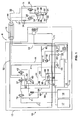
- ink is delivered under pressure from an ink supply system 10 to a print head 11 and back via flexible tubes which are bundled together with other fluid tubes and electrical wires (not shown) into what is referred to in the art as an "umbilical" conduit 12.
- the ink supply system 10 is located in a cabinet 13 which is typically table mounted and the print head 11 is disposed outside of the cabinet.
- ink is drawn from a reservoir of ink 14 in a mixer tank 15 by a system pump 16, the tank 15 being topped up as necessary with ink and make-up solvent from replaceable ink and solvent cartridges 17, 18.
- Ink is transferred under pressure from the ink cartridge 17 to the mixer tank 15 as required and solvent is drawn from the solvent cartridge 18 by suction pressure as will be described.
- the ink supply system 10 and the print head 11 include a number of flow control valves which are of the same general type: a dual coil solenoid-operated two-way, two port flow control valve.
- the operation of each of the valves is governed by a control system (not shown in the figures) that also controls operation of the pumps.
- Ink drawn from the tank 15 is filtered first by a coarse filter 20 upstream of the system pump 16 and then by a relatively fine main ink filter 21 downstream of the pump 16 before it is delivered to an ink feed line 22 to the print head 11.
- a fluid damper 23 of conventional configuration and disposed upstream of the main filter 21 removes pressure pulsations caused by the operation of the system pump 16.
- the drop generator 24 includes a nozzle 26 from which the pressurised ink is discharged and a piezoelectric oscillator 27 which creates pressure perturbations in the ink flow at a predetermined frequency and amplitude so as break up the ink stream into drops 28 of a regular size and spacing.
- the break up point is downstream of the nozzle 26 and coincides with a charge electrode 29 where a predetermined charge is applied to each drop 28. This charge determines the degree of deflection of the drop 28 as it passes a pair of deflection plates 30 between which a substantially constant electric field is maintained.
- Uncharged drops pass substantially undeflected to a gutter 31 from where they are recycled to the ink supply system 10 via return line 32.
- Charged drops are projected towards a substrate 33 that moves past the print head 11.
- the position at which each drop 28 impinges on the substrate 33 is determined by the amount of deflection of the drop and the speed of movement of the substrate. For example, if the substrate moves in a horizontal direction, the deflection of the drop determines its vertical position in the stroke of the character matrix.
- the temperature of the ink entering the print head 11 is maintained at a desired level by a heater 34 before it passes to the first control valve 25.
- a heater 34 In instances where the printer is started up from rest it is desirable to allow ink to bleed through the nozzle 26 without being projected toward the gutter 31 or substrate 33.
- the passage of the ink into the return line 32, whether it is the bleed flow or recycled unused ink captured by the gutter 31, is controlled by a second flow control valve 35.
- the returning ink is drawn back to the mixer tank 15 by a jet pump arrangement 36 and a third flow control valve 37 in the ink supply system 10.
- the ink supply system 10 is therefore also designed to supply make-up solvent as required so as to maintain the viscosity of the ink within a predefined range suitable for use.
- Such solvent provided from the cartridge 18, is also used to flush the print head 11 at appropriate times in order to keep it clear of blockages.
- the flush solvent is drawn through the system 10 by a flush pump valve 40 that is driven by a flow of ink in a branch conduit 41 under the control of a fourth flow control valve 42 as will be described below.
- the flush solvent is pumped out via a filter 43 through a flush line 44 (represented in dotted line in Figure 1 ) that extends from the supply system 10 through the umbilical conduit 12 to the first flow control valve 25 in the print head 11. After passing through the nozzle 26 and into the gutter 31 the solvent is drawn into the return line 32 via the second control valve 35 and to the third control valve 37. The returning solvent flows under suction pressure from the jet pump arrangement 36.
- the jet pump arrangement 36 includes a pair of parallel venturi pumps 50, 51 that are supplied by pressurised ink from a branch line 53 from the outlet of the main filter 21.
- the pumps are of known configuration and make use of the Bernoulli Principle whereby fluid flowing through a restriction in a conduit increases to a high velocity jet at the restriction and creates a low pressure area. If a side port is provided at the restriction this low pressure can be used to draw in and entrain a second fluid in a conduit connected to the side port.
- the pressurised ink flows through a pair of conduits 54, 55 and back to the mixer tank 15, each conduit 54, 55 having a side port 56, 57 at the venturi restriction.
- the increase in flow velocity of the ink creates a suction pressure at the side port 56, 57 and this serves to draw returning ink and/or solvent through lines 58, 59 when the third flow control valve 37 is open.
- the flow control valve 37 is operated such that the flow of returning ink/solvent to each venturi pump 50, 51 can be separately controlled. More specifically, the control system determines whether to allow flow through one or both venturi pumps 50, 51 depending on the temperature of the ink determined by a temperature sensor 60 in the branch line 53. If the ink has a relatively low temperature it will have a relatively high viscosity and therefore greater pumping power is required to draw ink back from the gutter 31 in which case both pumps 50, 51 should be operated.
- the ink has a relatively high temperature it will have a relatively low viscosity in which case the only one pump 50 is required to generate sufficient suction. Indeed operation of both the pumps should be avoided in the latter circumstance, as there would be a risk of air getting into the supply system, which serves to cause excess evaporation of the solvent, and therefore increased consumption of make-up solvent.
- the branch line 53 is connected to line 41 that conveys ink to the flush pump valve 40 via the fourth flow control valve 42.
- the valve 40 is a rolling diaphragm type in which a resilient "top-hat" diaphragm 61 divides a valve housing 62 into first and second variable volume chambers 63, 64. Ink is supplied under pressure to the first chamber 63 and make up solvent is delivered from the cartridge 18 through a solvent supply line 65 to the second chamber 64 via a pressure transducer 66 and a non-return valve 67.
- the higher pressure of the ink entering the first chamber 63 relative to the solvent serves to deflect the diaphragm 61 from its normal position as shown in Figure 1 , to a position where the volume of the first chamber 63 has increased at the expense of the volume of the second chamber 64 and solvent is forced out of the second chamber 64 and towards the print head 11 via the flush line 44. It is to be appreciated that other flush pump designs may be used to achieve the same operation.
- the atmosphere above the mixer tank 15 soon becomes saturated with solvent and this is drawn into a condenser unit 70 where it is condensed and allowed to drain back into a solvent return line 71 via a fifth control valve 72 of the ink supply system.
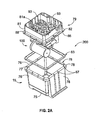
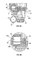
- the ink supply system 10, represented in circuit form in Figure 1 is physically embodied as a modular unit or core module 200 that is illustrated in Figures 2A to 2C and 11 .
- the mixer tank 15 includes a reservoir with a base wall 75, upstanding sidewalls 76 and an open top that defines a mouth 77.
- the side walls 76 terminate at their upper edge in a peripheral flange 78 around the mouth 77 and provide support for a manifold block 79, which provides fluid flow conduits between components of the ink supply system, many of which are conveniently supported on the block 79.
- the manifold block 79 includes two vertically stacked, interconnected parts: a tank-side feed plate 80 that supports a number of components over the ink in the tank 15 and an upper manifold plate 81 on which further components are supported.
- the plates 80, 81 which are shown in detail in Figures 3A to 3C and 4A to 4C , are generally square in outline, with the tank-side feed plate 80 being slightly smaller such that it fits inside the mouth 77 when the peripheral edge 82 of the manifold plate 81 rests on the flange 78 around the tank mouth 77.
- a seal 83 is provided between the flange 78 and the edge 82 of the manifold plate 81.
- Each of the plates 80, 81 has an upper and a lower surface 80a, 80b and 81 a, 81b, and the stacked arrangement is such that the lower surface 81b of the manifold plate overlies, and is in interfacing abutment with the upper surface 80a of the feed plate 80.
- the plates 80, 81 are penetrated in a direction substantially perpendicular to the plane of the interfacing surfaces 80a, 81b by a number of aligned fixing apertures 84 ( fig 3A ) for fixing screws (not shown) that are used to connect the plates together.
- the manifold plate 81 additionally has a plurality of apertures 86 spaced about its periphery for location over upstanding pegs 87 on the flange 78 of the tank 15, and a plurality of ports 88 (see Figure 3A ) for connection to components of the ink supply system 10.
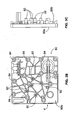
- the flow of ink between the ports 88, and therefore the components of the ink supply system, is provided by a plurality of discrete channels A to K defined in the lower surface 81b of the manifold plate 81.
- the channels A-K interconnect the ports 88 in a predetermined relationship as can be seen in Figures 3A and 4A .
- the channels A-K are covered by the upper surface 80a of the feed plate 80 and sealed by a sealing member 89 that is received in a pattern of recesses 90 defined in that surface 80a.
- the sealing member 89 is made from a moulded elastomeric material such as synthetic rubber of the kind used in O-ring seals and is compressed in the recesses when the plates 80, 81 are fastened together. It is configured such that it includes a plurality of ring seals, each designed to seal around a particular channel when the plates 80, 81 are brought together, the seals being interconnected to form one member for convenience.
- the sealing member 89 demarcates selected areas 91 of the upper surface 80a that generally correspond to the pattern of channels A-K defined on the manifold plate 81, these areas 91 serving to close the channels A-K whilst the sealing member 89 seals the channels A-K against leakage.
- Some of the areas 91 bounded by the sealing member 89 contain the ports 88 that allow fluid communication between the channels A-K and the components mounted on the feed plate 80.
- a plurality of spigots 92 extend substantially perpendicularly from the ports 88 on the lower surface 80b feed plate 80 and provide for easy connection of the components to the ports 88.
- the upper surface 81a of the manifold plate 81 has upstanding side walls 93 spaced inwardly of the peripheral apertures 86, the area inside the walls 93 being configured to support components of the ink supply system 10.
- Channel A defines the branch line 53 and connected line 41 for pressurised ink that extend from the outlet of the main filter 21, which is connected to port A5 on the feed plate 80, to the jet pump 36 inlet that is connected to port A1.
- Line 41 is connected to the fourth control valve 42 (which controls activation of the flush pump) via port A4.
- the pressure transducer 61 is in fluid communication with the conduit via port A3 and a temperature sensor 60 via port A2.
- Channel B interconnects the second venturi jet pump 51 and the third control valve 37 which allows the flow to pump 51 to be switched on and off.
- Port B1 in the manifold plate 81 is connected to the valve 37 and port B2 ( fig 3A ) in the feed plate 80 connects to the venturi pump 51.
- Channel C defines part of the ink return line 32 from the print head 11 and interconnects the return line (port C2) in the umbilical conduit 12 from the print head 11 to the third control valve 37 (port C3). Port C1 is not used.
- Channel D defines the conduit that carries the flow of ink returning from the first chamber 63 of the flush pump 40 (via the fourth control valve 42) to the first venturi pump 50 of the jet pump arrangement 36 and/or the recovered solvent from the condenser unit 70.
- Port D1 on the feed plate 80 connects to the first venturi pump 50, port D2 on the manifold plate 81 to an outlet of the third control valve 37, port D3 to the fourth control valve 42 and port D4 to the fifth control valve 72 (controlling the flow of recovered solvent from the condenser unit 70).
- Channel E defines the conduit 41 that delivers pressurised ink to the flush pump valve 40 and interconnects an outlet of the fourth control valve 42 (port E1 in the manifold plate 81) to the inlet (port E2 in the manifold plate 81) of the first chamber 63 of the flush pump valve 40.
- Channel F defines part of the solvent return line 71 from the condenser unit 70 and interconnects the condenser drain (port F1 in the manifold plate 81) to the fifth control valve 72 (at port F2 in the manifold plate 81).
- Channel G defines part of the solvent flush line 44 and interconnects that to the flush line tube in the umbilical conduit 12 to the print head 11 (port G1 on the manifold plate 81) and an outlet of the solvent flush filter 43 (port G2 on the feed plate 80).
- Channel H defines part of the ink feed line 22 and interconnects the outlet of the damper 23 (port H2 in the feed plate 80) and ink feed line tube in the umbilical conduit 12.
- Channel I defines the solvent supply line 65 from the solvent cartridge 18 and interconnects the end of a conduit from the cartridge 18 (that end being connected to port I4 in the manifold plate 81) to the fifth control valve 72 (port I1 in the manifold plate 81). It also provides fluid communication with the non-return valve 67 (port I2 in the feed plate 81) and the pressure transducer 66 (port 13).
- Channel J defines the solvent flow conduit between the non-return valve 67 and the flush pump 40.
- Port J1 in the feed plate 80 provides fluid communication between the inlet to the second chamber 64 of the flush pump 40 and port J2, also in the feed plate 80, with an outlet of the non-return valve 67.
- Channel K defines part of the main ink feed line 22 and extends between the outlet of the system pump 16 (port K2 on the manifold plate 81) and the inlet of the main filter 21 (port K1 on the feed plate 80).
- Ports L1 on the manifold plate 81 and L2 on the feed plate 80 simply allow a direct connection between the outlet of the coarse filter 20 and the inlet of the system pump 16 without any intermediate flow channel.
- Each of the interfacing surfaces 80a, 81b of the plates 80, 81 has a large cylindrical recess 95a, 95b which combine when the plates are brought together, so as to form a chamber 95 for housing the flush pump 40, as best seen in Figures 5A and 5B .
- the non-return valve 67 sits in a small chamber 96 defined between recesses 96a, 96b.
- the manifold block 79 configuration allows the various ink supply system components to be plugged simply into fluid communication with the ports 88 (or the spigots extending from the ports) and therefore the fluid flow channels in a modular fashion.
- An integrated filter and damper module 100 is connected to the lower surface 80b of the feed plate 80 by five spigots 92 as shown in Figures 2B and 2C . Two of the spigots are for mounting purposes only whereas the other spigots 92 extend rearwardly from ports K1, G2 and H2 in the plate.
- the module 100 shown separately in Figures 6A and 6B includes a pair of cylindrical housings 103, 104 that are integrally formed with a mounting support 105 for the damper 23 (not shown in Figures 6A and 6B but shown in Figures 2B, 2C and 5A ).
- a first housing 103 contains the main ink filter 21 and the second housing 104 houses the solvent filter 43.
- Each of the cylindrical housings 103, 104 has a central inlet opening 106 that fits over a respective spigot 92 in a friction fit, the opening for the main ink filter 21 connecting to the spigot at port K1 and the opening for the solvent filter 43 connecting to the spigot at port J2.
- a suitable sealing ring may be provided between each spigot 92 and inlet opening 106.
- the filtered ink egresses from the housing 103 at aperture 102, passes through the mounting support 105 to an inlet of the damper 23 and exits the damper and support 105 at aperture 23a to an integrally formed outlet conduit 107 that extends substantially parallel to the axis of the cylindrical housing 103, 104 and connects to the spigot 92 at port H2.
- a further conduit 108 extends from a side opening in the ink filter housing 103 and connects to the spigot 92 at port A5 from where the ink flows into the branch line 53 defined by channel A.
- the filtered solvent passes through a side aperture in the housing into a conduit 109 that connects to the spigot 92 at port G2 from where it flows into the flush line 44 defined by channel G.
- inlets 106 and the outlet conduits 107, 108, 109 are disposed substantially in parallel so that the module 100 can be plugged into the manifold block 79 with relative ease, with the inlets and conduits sliding on to the respective spigots 92.
- the filter and damper module 100 also includes the coarse filter 21 in a further cylindrical housing 110 whose inlet has a take up pipe 111 for connection to a tube (not shown) that extends into the ink 14 at the bottom of the mixer tank 15.
- the system pump 16 upstream of the coarse filter 21 operates to draw ink from the tank 15 through the take up pipe 111 and into the coarse filter 21.
- the outlet of the coarse filter 21 directs filtered ink along an integral right-angled outlet conduit 112 that connects to port L1 in the manifold plate from where ink flows to an inlet pipe 113 ( figures 4C and 5A ) of the system pump 16, which extends through ports L2 and L1 and into the end of the filter outlet conduit 112.
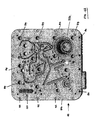
- the ink supply system 10 Several components of the ink supply system 10 are mounted on the upper surface 81a of the manifold plate 81, these include in particular the jet pump assembly 36, system pump 16, the third to fifth flow control valves 37, 42, 72, temperature sensor 60, pressure transducer 61, and a circuit board 115 for terminating electrical wiring connecting the valves, pumps and transducers to the control system. Many of these components are hidden from view in Figure 4B by the circuit board 115.
- the three flow lines 22, 32, 44 are partly defined by respective tubes in the umbilical conduit 12 as described above and these connect to the respect ports H1, C2, G1 that are conveniently grouped together at a connection block 116 ( figure 4B ) defined on the upper surface 81a of the manifold plate 81.
- the tubes are supported in cut-out notches 117 ( fig 2B ) in the side wall 93.
- An ink level sensor device 120 shown in Figures 2B, 2C , and 4C is provided on the manifold block 79 in order to detect the level of ink in the mixer tank at any given time. It includes four electrically conductive pins 121, 122, 123, 124 that depend from the lower surface 81b of the manifold plate 81. They extend through a slot 125 in the feed plate 80 and into the tank 15 where they are designed to dip into the ink 14.
- the first and second pins 121, 122 are of the same length; a third 123 of intermediate length and the fourth 124 has the shortest length.
- the pins are connected to one or more electrical sensors (e.g.
- the sensor 120 is designed to sense the presence of the electrically conductive ink when it completes an electrical circuit between the first pin 121 and one or more of the other pins 122, 123, 124. For example, when the level of ink in the tank is relatively high the ends of all of the pins 121-124 will be immersed in the ink and the sensor(s) detects that all the circuits are complete.
- ink and solvent returning into the tank from the return line 32 may cause turbulence, particularly at the surface of the ink 14, such that foam of bubbles is formed on the surface of the ink owing to surfactants present in the ink.
- a deflector plate may be used at the outlet of the return line to reduce the turbulence caused by the returning ink/solvent but this does not always eliminate foam entirely. The presence of the foam can mask the real level of ink in the tank and lead to erroneous readings by the level sensor 120.
- a guard 130 is connected to the lower surface 80b of the feed plate 80 and depends downwards into the tank 15 such that it shields the pins 120-124 from any surface foam generated by incoming ink or solvent.
- the guard 130 shown in detail in Figures 7A-D , includes a continuous thin wall made from, for example, a porous polypropylene material that has an upper end 130a with an integral laterally extending flange 131 for connecting to the feed plate 80 and a lower end 132 that, in use, is proximate to the base wall 75 of the tank 15.
- the wall tapers inwardly between its upper and lower end 130a, 130b and surrounds the pins 120-124 such that the ink within its confines is maintained substantially free of foam and a correct level reading can therefore be determined.
- the guard 130 may be used with any form of level sensor that depends upon immersion within the ink in the tank and that the wall may be manufactured from any suitable material, porous or otherwise.
- the mixer tank 15 is shown in more detail in Figures 8 to 10 .
- the base wall 75 of the tank 15 has a generally planar upper surface that is interrupted by a recess that defines a small, shallow well 151 in one corner 152.
- the well 151 is substantially square in the embodiment shown but it will be readily appreciated that any suitable shape may be adopted.
- the rest of the base wall 75 is inclined downwardly from the opposite corner 153 to the well 151 such that, in use, any residual ink remaining in the bottom of an otherwise empty tank will collect in the well 151 at the bottom of the incline. The inclination will be evident from an inspection of Figures 8 and 10 .
- the base wall is inclined downwardly in two orthogonal directions as represented by arrows A and B in Figures 9 and 10 .
- the base wall 75 is supported on its underside by a plurality of tapering ribs 154, 155 that provide strength and rigidity.
- a first set of three spaced parallel ribs 154 extend in a first direction and a second set of three spaced parallel ribs 155 extend in a second direction which is perpendicular to the first direction.
- the tube 150 that depends from the take up pipe 111 of the filter and module 100 is positioned such that its end extends into the well 151.
- the take up pipe 111 may extend directly into the well 151 without the need for a separate tube 150.
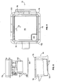
- FIG 11 shows an assembled core module 200.
- the module 200 is part of the ink supply system 10.
- the core module 200 preferably contains such components as the filter module 100, the ink reservoir/mixer tank 15, system pump 16, solvent filter 43, and so forth.
- Disposed on the surface of the module 200 is a connection manifold 202.
- connection manifold 202 includes a plurality of connection ports 204, which are in fluid communication with manifold block 79 (as shown in Figure 2A ).
- Connection manifold 202 is adapted to be connected with the ink jet printer 8 to provide ink, solvent, and so forth to the printer 8.
- Ports 204 may be located on a single surface 206 of the module 200.
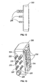
- Figure 13 shows a connector 220 of printer 8 that is configured for connection to manifold 200 to provide fluid communication between the module 200 and the printer 8.
- Connector 220 includes barbs 222, 224, 226 configured for connection to feed lines (not shown) of the ink jet printer 8. Additionally, openings 232, 234 of connector 220 are configured for connection to connection ports 204 of manifold 202. Although a particular configuration of ports, barbs, and openings is shown in the figures, other suitable configurations are possible.
- the configuration of connection ports 204 and connector 220 is preferably such that connector 220 is easily connected to the connection ports 204 of manifold 202 in an easy, one-step connection.
- the core module 200 may be connected to an ink jet printer 8 (as schematically shown in Figure 1 ) as follows.
- the printer connector 220 is connected to the manifold 202 to provide fluid communication of ink between the module components and the ink jet printer 8.
- An electrical connection (not shown) between the module 200 and the ink jet printer 8 may also be provided.
- the electrical connection may be any suitable connection, but preferably includes electrical wires with a socket connection.
- the ink jet printer 8 may include a receiving bay (not shown) disposed in cabinet 13.
- the core module 200 may be disposed in the receiving bay of the cabinet 13 while the printer is in use.
- the core module 200 is capable of being operably connected to the ink jet printer 8, to provide ink filtration and a fluid reservoir for the ink jet printer 8, in no more than three steps.
- the three steps include disposing the module 200 adjacent to the printer 8 (such as within the printer cabinet 13); providing an electrical connection between the module 200 and the printer 8; and connecting the connector 220 to the manifold 202.
- the electrical connection may include a plurality of wires with a socket connection between the printer 8 and the core module 200, thus providing all electrical connections within a single connection.
- the fluid communication into and out of the module 200 between the ink circuit and the ink jet printer 8 may be solely provided through the plurality of connection ports 204.
- the connection between manifold 202 and connector 220 provides all the fluid communication between module 200 and ink jet printer 8, without the need for additional connections. This arrangement greatly simplifies the process of installing and replacing the module 200.
- the configuration of the manifold block and in particular the channels defined at the interface between the manifold plate and the feed plate obviates the need for many pipes, tubes, hoses or the like that interconnect the components of the ink supply system.
- the arrangement is thus much simpler to assemble thus reducing the time associated with building the system and the likelihood of errors occurring.
- the area inside the cabinet is much tidier such that it is easier to access individual components.
- the manifold block also eliminates connectors associated with such pipes, which are potential sources of leaks. The reliability of the system is therefore improved thus reducing servicing requirements.
- the general structure of the manifold block provides for a compact arrangement.
- flush pump may be on any suitable kind besides a rolling diaphragm pump.
Abstract
Claims (13)
- Système d'alimentation d'encre (10) pour une imprimante à jet d'encre (8), le système comprenant :un circuit d'encre, comprenant plusieurs composants de circuit (16, 25, 36, 37, 40, 42, 50, 51, 60, 61, 66, 67, 72, 100) et plusieurs trajectoires de fluide (41, 44, 53, 58, 59, 85, 71) pour transférer l'encre entre les composants ;un collecteur (79) définissant les trajectoires de fluide et plusieurs orifices (88), en communication de fluide avec les trajectoires ;une première trajectoire des trajectoires de fluide étant une trajectoire d'alimentation en solvant (65) pour une connexion à une source de solvant (18) ;une deuxième trajectoire des trajectoires de fluide étant une trajectoire d'évacuation de solvant (44) pour amener le solvant vers une sortie en vue d'une connexion à une tête d'impression (11) de l'imprimante ;un des composants étant constitué par une pompe d'évacuation agencée au niveau du collecteur (79) entre les première et deuxième trajectoires et étant en communication de fluide avec celles-ci, la pompe étant configurée de sorte à pomper le solvant dans la trajectoire d'évacuation du solvant (44) ;dans lequella pompe d'évacuation (40) est logée dans une cavité (95) définie dans le collecteur ;et dans lequel le collecteur comprend des premier et deuxième éléments (80, 81), comportant des premières surfaces d'interface (80a, 81b), la cavité étant définie dans une des premières surfaces ou dans les deux.
- Système d'alimentation d'encre selon la revendication 1, dans lequel la pompe d'évacuation (40) est supportée par le collecteur (79).
- Système d'alimentation d'encre selon la revendication 1 ou 2, dans lequel la pompe d'évacuation (40) est connectée à au moins un des plusieurs orifices (88).
- Système d'alimentation d'encre selon la revendication 1, 2 ou 3, dans lequel la cavité (95) est définie par une première partie de cavité (95a) dans la première surface (80a) du premier élément de collecteur (80), et une deuxième partie de cavité (95b) définie dans la première surface (81a) du deuxième élément de collecteur (81).
- Système d'alimentation d'encre selon l'une quelconque des revendications précédentes, comportant une troisième trajectoire de fluide (41) pour de l'encre sous pression, la troisième trajectoire étant connectée à une entrée de la pompe (40), de sorte que l'actionnement de la pompe est assuré par l'alimentation d'encre.
- Système d'alimentation d'encre selon la revendication 5, dans lequel la pompe (40) comprend une première chambre à volume variable (83), connectée aux première et deuxième trajectoires (66, 44), et une deuxième chambre à volume variable (64) connectée à la troisième trajectoire (41), les chambres étant séparées par une paroi mobile (61).
- Système d'alimentation d'encre selon la revendication 6, dans lequel la paroi mobile est une membrane flexible (61).
- Système d'alimentation d'encre selon la revendication 7, dans lequel la membrane (61) peut être fléchie sous pression, de sorte à changer les volumes des première et deuxième chambres (63, 64).
- Système d'alimentation d'encre selon la revendication 6, 7 ou 8, dans lequel les première et deuxième chambres (63, 64) sont définies dans un boîtier (62).
- Système d'alimentation d'encre selon la revendication 9, dans lequel le boîtier (62) est défini par le collecteur (79).
- Système d'alimentation d'encre selon l'une quelconque des revendications précédentes, comportant un conduit entre la pompe d'évacuation (40) et un orifice (E2) auquel elle est connectée, le conduit (41) étant défini par le collecteur (79).
- Imprimante à jet d'encre (8), comprenant une tête d'impression (11) pour produire des gouttelettes d'encre en vue d'une impression sur un substrat, et un système d'alimentation d'encre (10) selon l'une quelconque des revendications précédentes.
- Imprimante à jet d'encre selon la revendication 12, dans laquelle l'imprimante (8) est du type continu, comportant un receveur (31) au niveau de la tête d'impression (11), pour recevoir les gouttelettes d'encre produites et non utilisées, et une trajectoire de retour de l'encre (32) pour ramener l'encre vers le système d'alimentation d'encre (10).
Applications Claiming Priority (4)
| Application Number | Priority Date | Filing Date | Title |
|---|---|---|---|
| GB0720133A GB0720133D0 (en) | 2007-10-12 | 2007-10-12 | Ink jet printing |
| GB0720051A GB0720051D0 (en) | 2007-10-15 | 2007-10-15 | Ink jet printing |
| US8128308P | 2008-07-16 | 2008-07-16 | |
| PCT/US2008/079497 WO2009049141A1 (fr) | 2007-10-12 | 2008-10-10 | Pompe d'évacuation pour système d'alimentation en encre |
Publications (3)
| Publication Number | Publication Date |
|---|---|
| EP2200832A1 EP2200832A1 (fr) | 2010-06-30 |
| EP2200832A4 EP2200832A4 (fr) | 2011-06-15 |
| EP2200832B1 true EP2200832B1 (fr) | 2012-07-25 |
Family
ID=40549583
Family Applications (1)
| Application Number | Title | Priority Date | Filing Date |
|---|---|---|---|
| EP08838199A Active EP2200832B1 (fr) | 2007-10-12 | 2008-10-10 | Pompe d'évacuation pour système d'alimentation en encre |
Country Status (5)
| Country | Link |
|---|---|
| US (1) | US8425018B2 (fr) |
| EP (1) | EP2200832B1 (fr) |
| KR (1) | KR101510767B1 (fr) |
| CN (1) | CN101896356B (fr) |
| WO (1) | WO2009049141A1 (fr) |
Families Citing this family (4)
| Publication number | Priority date | Publication date | Assignee | Title |
|---|---|---|---|---|
| JP5274172B2 (ja) * | 2008-09-17 | 2013-08-28 | 株式会社日立産機システム | インクジェット記録装置 |
| GB201019687D0 (en) * | 2010-11-19 | 2011-01-05 | Domino Printing Sciences Plc | Improvements in or relating to inkjet printers |
| FR3048199B1 (fr) * | 2016-02-26 | 2019-09-06 | Dover Europe Sarl | Dispositif simplifie d'alimentation d'un circuit d'encre |
| KR102090552B1 (ko) * | 2019-12-26 | 2020-03-18 | 주식회사 고산테크 | 매니폴드 및 이를 적용한 잉크젯 헤드의 잉크 순환 펌프 시스템 |
Family Cites Families (24)
| Publication number | Priority date | Publication date | Assignee | Title |
|---|---|---|---|---|
| CA2009631C (fr) | 1989-02-17 | 1994-09-20 | Shigeo Nonoyama | Amortisseur de pression pour machine a imprimer au jet d'encre |
| JPH0699586A (ja) | 1992-09-22 | 1994-04-12 | Fuji Electric Co Ltd | インクジェット・プリンタ |
| US5742314A (en) | 1994-03-31 | 1998-04-21 | Compaq Computer Corporation | Ink jet printhead with built in filter structure |
| EP0813974B1 (fr) | 1996-06-18 | 2003-03-12 | SCITEX DIGITAL PRINTING, Inc. | Tête d'impression par jet d'encre continu |
| JPH10193646A (ja) | 1997-01-09 | 1998-07-28 | Seiko Epson Corp | 印刷ヘッドユニット、これを備えたインクジェットプリンタおよびインクカートリッジ |
| GB9719705D0 (en) * | 1997-09-16 | 1997-11-19 | Domino Printing Sciences Plc | Ink jet printer |
| ES1040834Y (es) | 1998-08-07 | 1999-10-16 | Investronica Sistemas S A | Dispositivo del circuito de alimentacion de tinta en maquinas de dibujo raster. |
| US6273103B1 (en) | 1998-12-14 | 2001-08-14 | Scitex Digital Printing, Inc. | Printhead flush and cleaning system and method |
| JP4202510B2 (ja) | 1999-02-05 | 2008-12-24 | 株式会社キーエンス | インクジェット記録装置 |
| EP1083054A1 (fr) | 1999-09-09 | 2001-03-14 | De La Rue Giori S.A. | Agencement d'imprimante à jet d'encre continu |
| US6257699B1 (en) | 1999-10-13 | 2001-07-10 | Xerox Corporation | Modular carriage assembly for use with high-speed, high-performance, printing device |
| US6488368B2 (en) | 2001-01-26 | 2002-12-03 | Hewlett-Packard Company | Manifold for providing fluid connections between carriage-mounted ink containers and printheads |
| AUPR399601A0 (en) | 2001-03-27 | 2001-04-26 | Silverbrook Research Pty. Ltd. | An apparatus and method(ART108) |
| JP4193435B2 (ja) | 2002-07-23 | 2008-12-10 | ブラザー工業株式会社 | インクカートリッジ、および、そのインク充填方法 |
| JP2003220713A (ja) | 2002-01-31 | 2003-08-05 | Hitachi Ltd | インクジェット記録装置 |
| US6948801B2 (en) | 2002-04-04 | 2005-09-27 | Hewlett-Packard Development Company, L.P. | Fluid interconnect with sealant |
| JP3995996B2 (ja) | 2002-06-21 | 2007-10-24 | エスアイアイ・プリンテック株式会社 | インクジェットヘッド及びインクジェット式記録装置 |
| JP2005096209A (ja) | 2003-09-24 | 2005-04-14 | Olympus Corp | インク流路の封止機構 |
| US7210771B2 (en) | 2004-01-08 | 2007-05-01 | Eastman Kodak Company | Ink delivery system with print cartridge, container and reservoir apparatus and method |
| GB2412088B (en) * | 2004-03-19 | 2007-09-19 | Zipher Ltd | Liquid supply system |
| JP4682862B2 (ja) | 2005-03-31 | 2011-05-11 | セイコーエプソン株式会社 | 液体収容体及びその液体充填方法 |
| JP2007230227A (ja) | 2006-02-01 | 2007-09-13 | Seiko Epson Corp | 液体噴射装置およびその初期充填方法 |
| JP2007260947A (ja) | 2006-03-27 | 2007-10-11 | Seiko Epson Corp | 液体供給装置及び液体噴射装置 |
| JP2007301880A (ja) | 2006-05-12 | 2007-11-22 | Brother Ind Ltd | インクジェット記録装置 |
-
2008
- 2008-10-10 EP EP08838199A patent/EP2200832B1/fr active Active
- 2008-10-10 CN CN200880120695XA patent/CN101896356B/zh active Active
- 2008-10-10 US US12/681,069 patent/US8425018B2/en active Active
- 2008-10-10 WO PCT/US2008/079497 patent/WO2009049141A1/fr active Application Filing
- 2008-10-10 KR KR1020107010473A patent/KR101510767B1/ko active IP Right Grant
Also Published As
| Publication number | Publication date |
|---|---|
| EP2200832A4 (fr) | 2011-06-15 |
| US8425018B2 (en) | 2013-04-23 |
| KR20100088631A (ko) | 2010-08-09 |
| EP2200832A1 (fr) | 2010-06-30 |
| US20100220159A1 (en) | 2010-09-02 |
| KR101510767B1 (ko) | 2015-04-10 |
| CN101896356B (zh) | 2012-10-03 |
| WO2009049141A1 (fr) | 2009-04-16 |
| CN101896356A (zh) | 2010-11-24 |
Similar Documents
| Publication | Publication Date | Title |
|---|---|---|
| US9694590B2 (en) | Ink supply system | |
| EP2200834B1 (fr) | Filtre pour système d'alimentation en encre | |
| EP2200831B1 (fr) | Système d'alimentation en encre | |
| EP2217447B1 (fr) | Impression à jet d'encre | |
| US20100220128A1 (en) | Ink jet printer | |
| US8449054B2 (en) | Ink jet printer | |
| EP2200832B1 (fr) | Pompe d'évacuation pour système d'alimentation en encre |
Legal Events
| Date | Code | Title | Description |
|---|---|---|---|
| PUAI | Public reference made under article 153(3) epc to a published international application that has entered the european phase |
Free format text: ORIGINAL CODE: 0009012 |
|
| 17P | Request for examination filed |
Effective date: 20100419 |
|
| AK | Designated contracting states |
Kind code of ref document: A1 Designated state(s): AT BE BG CH CY CZ DE DK EE ES FI FR GB GR HR HU IE IS IT LI LT LU LV MC MT NL NO PL PT RO SE SI SK TR |
|
| AX | Request for extension of the european patent |
Extension state: AL BA MK RS |
|
| DAX | Request for extension of the european patent (deleted) | ||
| REG | Reference to a national code |
Ref country code: DE Ref legal event code: R079 Ref document number: 602008017460 Country of ref document: DE Free format text: PREVIOUS MAIN CLASS: B41J0002175000 Ipc: B41J0002190000 |
|
| A4 | Supplementary search report drawn up and despatched |
Effective date: 20110513 |
|
| RIC1 | Information provided on ipc code assigned before grant |
Ipc: B41J 2/175 20060101ALI20110509BHEP Ipc: B41J 2/19 20060101AFI20110509BHEP |
|
| GRAP | Despatch of communication of intention to grant a patent |
Free format text: ORIGINAL CODE: EPIDOSNIGR1 |
|
| GRAS | Grant fee paid |
Free format text: ORIGINAL CODE: EPIDOSNIGR3 |
|
| GRAA | (expected) grant |
Free format text: ORIGINAL CODE: 0009210 |
|
| AK | Designated contracting states |
Kind code of ref document: B1 Designated state(s): AT BE BG CH CY CZ DE DK EE ES FI FR GB GR HR HU IE IS IT LI LT LU LV MC MT NL NO PL PT RO SE SI SK TR |
|
| REG | Reference to a national code |
Ref country code: GB Ref legal event code: FG4D |
|
| REG | Reference to a national code |
Ref country code: CH Ref legal event code: EP |
|
| REG | Reference to a national code |
Ref country code: AT Ref legal event code: REF Ref document number: 567530 Country of ref document: AT Kind code of ref document: T Effective date: 20120815 Ref country code: IE Ref legal event code: FG4D |
|
| REG | Reference to a national code |
Ref country code: DE Ref legal event code: R096 Ref document number: 602008017460 Country of ref document: DE Effective date: 20120920 |
|
| REG | Reference to a national code |
Ref country code: NL Ref legal event code: VDEP Effective date: 20120725 |
|
| REG | Reference to a national code |
Ref country code: AT Ref legal event code: MK05 Ref document number: 567530 Country of ref document: AT Kind code of ref document: T Effective date: 20120725 |
|
| REG | Reference to a national code |
Ref country code: LT Ref legal event code: MG4D Effective date: 20120725 |
|
| PG25 | Lapsed in a contracting state [announced via postgrant information from national office to epo] |
Ref country code: BE Free format text: LAPSE BECAUSE OF FAILURE TO SUBMIT A TRANSLATION OF THE DESCRIPTION OR TO PAY THE FEE WITHIN THE PRESCRIBED TIME-LIMIT Effective date: 20120725 Ref country code: FI Free format text: LAPSE BECAUSE OF FAILURE TO SUBMIT A TRANSLATION OF THE DESCRIPTION OR TO PAY THE FEE WITHIN THE PRESCRIBED TIME-LIMIT Effective date: 20120725 Ref country code: IS Free format text: LAPSE BECAUSE OF FAILURE TO SUBMIT A TRANSLATION OF THE DESCRIPTION OR TO PAY THE FEE WITHIN THE PRESCRIBED TIME-LIMIT Effective date: 20121125 Ref country code: CY Free format text: LAPSE BECAUSE OF FAILURE TO SUBMIT A TRANSLATION OF THE DESCRIPTION OR TO PAY THE FEE WITHIN THE PRESCRIBED TIME-LIMIT Effective date: 20120725 Ref country code: NO Free format text: LAPSE BECAUSE OF FAILURE TO SUBMIT A TRANSLATION OF THE DESCRIPTION OR TO PAY THE FEE WITHIN THE PRESCRIBED TIME-LIMIT Effective date: 20121025 Ref country code: AT Free format text: LAPSE BECAUSE OF FAILURE TO SUBMIT A TRANSLATION OF THE DESCRIPTION OR TO PAY THE FEE WITHIN THE PRESCRIBED TIME-LIMIT Effective date: 20120725 Ref country code: HR Free format text: LAPSE BECAUSE OF FAILURE TO SUBMIT A TRANSLATION OF THE DESCRIPTION OR TO PAY THE FEE WITHIN THE PRESCRIBED TIME-LIMIT Effective date: 20120725 Ref country code: LT Free format text: LAPSE BECAUSE OF FAILURE TO SUBMIT A TRANSLATION OF THE DESCRIPTION OR TO PAY THE FEE WITHIN THE PRESCRIBED TIME-LIMIT Effective date: 20120725 |
|
| PG25 | Lapsed in a contracting state [announced via postgrant information from national office to epo] |
Ref country code: SE Free format text: LAPSE BECAUSE OF FAILURE TO SUBMIT A TRANSLATION OF THE DESCRIPTION OR TO PAY THE FEE WITHIN THE PRESCRIBED TIME-LIMIT Effective date: 20120725 Ref country code: PT Free format text: LAPSE BECAUSE OF FAILURE TO SUBMIT A TRANSLATION OF THE DESCRIPTION OR TO PAY THE FEE WITHIN THE PRESCRIBED TIME-LIMIT Effective date: 20121126 Ref country code: LV Free format text: LAPSE BECAUSE OF FAILURE TO SUBMIT A TRANSLATION OF THE DESCRIPTION OR TO PAY THE FEE WITHIN THE PRESCRIBED TIME-LIMIT Effective date: 20120725 Ref country code: SI Free format text: LAPSE BECAUSE OF FAILURE TO SUBMIT A TRANSLATION OF THE DESCRIPTION OR TO PAY THE FEE WITHIN THE PRESCRIBED TIME-LIMIT Effective date: 20120725 Ref country code: GR Free format text: LAPSE BECAUSE OF FAILURE TO SUBMIT A TRANSLATION OF THE DESCRIPTION OR TO PAY THE FEE WITHIN THE PRESCRIBED TIME-LIMIT Effective date: 20121026 Ref country code: PL Free format text: LAPSE BECAUSE OF FAILURE TO SUBMIT A TRANSLATION OF THE DESCRIPTION OR TO PAY THE FEE WITHIN THE PRESCRIBED TIME-LIMIT Effective date: 20120725 |
|
| PG25 | Lapsed in a contracting state [announced via postgrant information from national office to epo] |
Ref country code: NL Free format text: LAPSE BECAUSE OF FAILURE TO SUBMIT A TRANSLATION OF THE DESCRIPTION OR TO PAY THE FEE WITHIN THE PRESCRIBED TIME-LIMIT Effective date: 20120725 |
|
| PG25 | Lapsed in a contracting state [announced via postgrant information from national office to epo] |
Ref country code: CZ Free format text: LAPSE BECAUSE OF FAILURE TO SUBMIT A TRANSLATION OF THE DESCRIPTION OR TO PAY THE FEE WITHIN THE PRESCRIBED TIME-LIMIT Effective date: 20120725 Ref country code: RO Free format text: LAPSE BECAUSE OF FAILURE TO SUBMIT A TRANSLATION OF THE DESCRIPTION OR TO PAY THE FEE WITHIN THE PRESCRIBED TIME-LIMIT Effective date: 20120725 Ref country code: EE Free format text: LAPSE BECAUSE OF FAILURE TO SUBMIT A TRANSLATION OF THE DESCRIPTION OR TO PAY THE FEE WITHIN THE PRESCRIBED TIME-LIMIT Effective date: 20120725 Ref country code: ES Free format text: LAPSE BECAUSE OF FAILURE TO SUBMIT A TRANSLATION OF THE DESCRIPTION OR TO PAY THE FEE WITHIN THE PRESCRIBED TIME-LIMIT Effective date: 20121105 Ref country code: DK Free format text: LAPSE BECAUSE OF FAILURE TO SUBMIT A TRANSLATION OF THE DESCRIPTION OR TO PAY THE FEE WITHIN THE PRESCRIBED TIME-LIMIT Effective date: 20120725 |
|
| PG25 | Lapsed in a contracting state [announced via postgrant information from national office to epo] |
Ref country code: MC Free format text: LAPSE BECAUSE OF NON-PAYMENT OF DUE FEES Effective date: 20121031 Ref country code: SK Free format text: LAPSE BECAUSE OF FAILURE TO SUBMIT A TRANSLATION OF THE DESCRIPTION OR TO PAY THE FEE WITHIN THE PRESCRIBED TIME-LIMIT Effective date: 20120725 Ref country code: IT Free format text: LAPSE BECAUSE OF FAILURE TO SUBMIT A TRANSLATION OF THE DESCRIPTION OR TO PAY THE FEE WITHIN THE PRESCRIBED TIME-LIMIT Effective date: 20120725 |
|
| PLBE | No opposition filed within time limit |
Free format text: ORIGINAL CODE: 0009261 |
|
| REG | Reference to a national code |
Ref country code: CH Ref legal event code: PL |
|
| STAA | Information on the status of an ep patent application or granted ep patent |
Free format text: STATUS: NO OPPOSITION FILED WITHIN TIME LIMIT |
|
| 26N | No opposition filed |
Effective date: 20130426 |
|
| REG | Reference to a national code |
Ref country code: IE Ref legal event code: MM4A |
|
| PG25 | Lapsed in a contracting state [announced via postgrant information from national office to epo] |
Ref country code: LI Free format text: LAPSE BECAUSE OF NON-PAYMENT OF DUE FEES Effective date: 20121031 Ref country code: CH Free format text: LAPSE BECAUSE OF NON-PAYMENT OF DUE FEES Effective date: 20121031 Ref country code: BG Free format text: LAPSE BECAUSE OF FAILURE TO SUBMIT A TRANSLATION OF THE DESCRIPTION OR TO PAY THE FEE WITHIN THE PRESCRIBED TIME-LIMIT Effective date: 20121025 Ref country code: IE Free format text: LAPSE BECAUSE OF NON-PAYMENT OF DUE FEES Effective date: 20121010 |
|
| REG | Reference to a national code |
Ref country code: DE Ref legal event code: R097 Ref document number: 602008017460 Country of ref document: DE Effective date: 20130426 |
|
| PG25 | Lapsed in a contracting state [announced via postgrant information from national office to epo] |
Ref country code: MT Free format text: LAPSE BECAUSE OF FAILURE TO SUBMIT A TRANSLATION OF THE DESCRIPTION OR TO PAY THE FEE WITHIN THE PRESCRIBED TIME-LIMIT Effective date: 20120725 |
|
| PG25 | Lapsed in a contracting state [announced via postgrant information from national office to epo] |
Ref country code: TR Free format text: LAPSE BECAUSE OF FAILURE TO SUBMIT A TRANSLATION OF THE DESCRIPTION OR TO PAY THE FEE WITHIN THE PRESCRIBED TIME-LIMIT Effective date: 20120725 |
|
| PG25 | Lapsed in a contracting state [announced via postgrant information from national office to epo] |
Ref country code: LU Free format text: LAPSE BECAUSE OF NON-PAYMENT OF DUE FEES Effective date: 20121010 |
|
| PG25 | Lapsed in a contracting state [announced via postgrant information from national office to epo] |
Ref country code: HU Free format text: LAPSE BECAUSE OF FAILURE TO SUBMIT A TRANSLATION OF THE DESCRIPTION OR TO PAY THE FEE WITHIN THE PRESCRIBED TIME-LIMIT Effective date: 20081010 |
|
| REG | Reference to a national code |
Ref country code: FR Ref legal event code: PLFP Year of fee payment: 8 |
|
| REG | Reference to a national code |
Ref country code: FR Ref legal event code: PLFP Year of fee payment: 9 |
|
| REG | Reference to a national code |
Ref country code: FR Ref legal event code: PLFP Year of fee payment: 10 |
|
| REG | Reference to a national code |
Ref country code: FR Ref legal event code: PLFP Year of fee payment: 11 |
|
| PGFP | Annual fee paid to national office [announced via postgrant information from national office to epo] |
Ref country code: FR Payment date: 20190913 Year of fee payment: 12 |
|
| PG25 | Lapsed in a contracting state [announced via postgrant information from national office to epo] |
Ref country code: FR Free format text: LAPSE BECAUSE OF NON-PAYMENT OF DUE FEES Effective date: 20201031 |
|
| P01 | Opt-out of the competence of the unified patent court (upc) registered |
Effective date: 20230530 |
|
| PGFP | Annual fee paid to national office [announced via postgrant information from national office to epo] |
Ref country code: GB Payment date: 20230817 Year of fee payment: 16 |
|
| PGFP | Annual fee paid to national office [announced via postgrant information from national office to epo] |
Ref country code: DE Payment date: 20230822 Year of fee payment: 16 |