EP2200472B1 - Bijou de taille réglable - Google Patents
Bijou de taille réglable Download PDFInfo
- Publication number
- EP2200472B1 EP2200472B1 EP07841459.6A EP07841459A EP2200472B1 EP 2200472 B1 EP2200472 B1 EP 2200472B1 EP 07841459 A EP07841459 A EP 07841459A EP 2200472 B1 EP2200472 B1 EP 2200472B1
- Authority
- EP
- European Patent Office
- Prior art keywords
- ring
- channel
- size adjustment
- width
- size
- Prior art date
- Legal status (The legal status is an assumption and is not a legal conclusion. Google has not performed a legal analysis and makes no representation as to the accuracy of the status listed.)
- Not-in-force
Links
Images


Classifications
-
- A—HUMAN NECESSITIES
- A44—HABERDASHERY; JEWELLERY
- A44C—PERSONAL ADORNMENTS, e.g. JEWELLERY; COINS
- A44C9/00—Finger-rings
- A44C9/02—Finger-rings adjustable
Definitions
- the present invention is directed to an improvement in jewelry, and more specifically relates to an item of jewelry, such as a ring or a bracelet suitable for wearing over a person's finger or wrist, having a spring actuated size adjustment mechanism.
- ring sizes or a wrist size in the case of a bracelet
- various factors ultimately affect a person's actual ring size on a given day For example, various physiological conditions are known to affect ring size. A person's fingers might swell as a result of hormonal changes or water retention. Water retention might be exacerbated by other factors such as the amount of salt intake as part of a person's diet. Weight gain and weight loss over a period of time also affect a person's ring size. Even weather conditions on a given day may affect ring size. Additionally, often a person's knuckles are greater in size than the person's ring size. As a result, it is often difficult to get a properly sized ring placed over a person's knuckle.
- a person's ring size may vary greatly from one day to the next, from one season to the next, and from one year to the next. Since people often purchase jewelry to be worn frequently, or even daily, over a large period of time, these changes in ring size have proven to be annoying, costly and extremely problematic. For example, if a person's ring is too tight on a given day, the person might not be able to place the ring on his or her finger that day and might be forced to leave it at home. This is very annoying to a person who purchased the ring to wear every day, or who merely wanted to wear the ring on that particular day. Similar problems may arise if the ring is too loose on a given day and a person is forced to leave the ring at home or alternatively risk losing the ring if it falls off the person's finger unexpectedly.
- Sizing down a ring can also be accomplished in a variety of ways. Where the change is small, the size can be made smaller by mechanically compressing the ring. If the ring is made of several metals (such as white and yellow gold), compression is typically not used as it might result in breaking the two metals apart. Where the change of size is greater, or where stones are included in the ring, sizing down the ring requires removing any stones. cutting out a portion of the ring, and then re-soldering the remaining portions together. This method is more costly and provides a greater risk of damaging the ring.
- U.S. Patent No. 5,412,956 to Levy discloses a variable sized hinged ring that may be worn in a closed position or in a number of open positions.
- the ring includes a center shank member and first and second side shank members, each of which is hinged to the center shank member and an elongated sizing section that has a plurality of stops for determining the circumferential ring size.
- the ring can be opened and closed by the wearer to provide several different ring sizes.
- One problem with this system is that it can only accommodate the ring sizes corresponding to the stops provided.
- Another problem is that is must be manually opened and closed by the user.
- the interior surface of the ring no longer presents a smooth, uninterrupted surface to the wearer and is thus very uncomfortable to wear.
- the finger opening no longer has a generally constant shape and therefore the appearance to the user and others is much less attractive than a standard shaped ring.
- Erb discloses a self sizing adjustable ring including a U-shaped shank member and a bridge member permanently connected to the shank member but movable up and down the shank member to adjust for the size of a user's fingers.
- the bridge member is manually adjustable by the user over a variety of different positions and is held in place using a frictional force created between the bridge and the shank member.
- One problem with this system is that it can only be used with U-shaped ring bodies.
- Another problem is that the bridge member is kept in place using frictional forces. It would be quite easy for the bridge member to disengage and move unintentionally.
- the disclosed ring design requires a securement member attached to the bridge member to frictionally engage the exterior surface of the shank member. This results in an unattractive appearance to the user and others because the disclosed ring does not provide the appearance of an ordinary ring.
- Miller discloses a finger ring size adjusting device and method including a ring shank and a cradle which is biased radially inward from the shank and is moveable between a retracted position and an adjusted position for reducing ring size.
- the cradle may be biased inwardly toward the adjusted position by a leaf spring in one embodiment, and by a lever arm in an alternate embodiment.
- One problem with this system is that the disclosed system includes only one cradle at the bottom of the ring shank. Only two possible ring sizes are provided - a smaller ring size and a larger ring size. There is no accommodation of a variety of ring sizes.
- the ring when the cradle is in its inward position, the ring does not provide a unitary, smooth, generally round inner surface.
- the inner surface would include gaps in which a user's skin could become pinched.
- the appearance of the ring is less attractive as the lever or spring is visible through the opening in the ring.
- Another ring adjustment device is known from DE-11 40 768 B .
- a ring having a size that can be adjusted simply and easily by the wearer to account for day to day fluctuations in a person's ring size and to account for variations in finger size such as those caused by a larger knuckle region.
- an adjustable ring that can accommodate a variety of different ring sizes within a specified range.
- an adjustable ring such that a jeweler can stock rings in fewer sizes.
- One embodiment of the present invention is directed to adjustable jewelry according to the claims comprising a ring portion having an outer surface and an inner surface defining an opening for receiving an appendage of a wearer therethrough; a channel is formed into the ring portion, a plurality of size adjustment segments are disposed in the channel, and an elastic member is disposed in the channel to bias the segments radially inwardly.
- the ring includes a ring body 100 having an opening 160 for receiving a finger therethrough.
- the size of the opening 160 corresponds to the ring size.
- the ring body 100 includes an outer surface 114 and an inner surface 112.
- the inner and outer surfaces 112, 114 have a generally circular or arcuate shape and form a generally cylindrical body.
- the outer surface 114 may include any manner of design or decoration and may include one or more jeweled stones, such as diamonds, mounted thereon.
- the outer and inner surfaces define a thickness (t) of the ring body 100, which can he selected as desired as is known in the art.
- the ring body 100 may be formed of any of a variety of materials, such as gold or silver, or any combination of materials, such as white and yellow gold.
- the ring body 100 may be formed in any of a variety of sizes by varying the diameter (d, d+t) of the inner and outer surfaces 112, 114, respectively, the thickness (t) and the width (w) of the ring body 100.
- the adjustable ring according to this first embodiment also includes an insert portion 110.
- the insert portion 110 may be formed of a variety of materials but is preferably formed of the same material as the ring body 100.
- the insert portion 110 preferably has the same width (w) as the ring body 100, but a slightly smaller diameter so that it may be placed inside of the inner surface 112 of the ring body 100. Alternatively, a smaller width (w) may be selected.
- the insert portion 110 is press fit into the ring body 100 so that it remains firmly in place.
- the insert 110 may be integrally formed with the ring body 100.
- the inner surface 112 of the ring body may include a grooved region or channel (not shown) into which the insert 110 may be placed.
- the insert portion 110 includes an outer surface 116 which cooperates with the inner surface 112 of the ring body, and an inner surface 118.
- the insert portion 110 includes at least one opening 120 through which a movable segment 130 can move, although a plurality of openings 120 can be incorporated.
- the insert portion 110 includes four openings 120 such that one of four movable segments can move through each of the openings 120.
- the adjustable ring also includes one or more movable segments 130.
- the adjustable ring includes four movable segments 130, each of which is movable through a respective opening 120 in the insert portion, such that the segments 130 can move between a first position and a second position.
- the movable segments 130 include an outer surface 132 and an inner surface 134, the inner surface 134 contacting the finger of the wearer.
- the outer surface 132 of the movable segment is coupled to one or more spring elements 140 to allow movement of the movable segment 130.
- the outer surface 132 of the movable segments include one or more nesting regions 135 in which the spring elements 140 may be placed.
- each movable segment 130 includes three nests 135, each of which houses an individual spring element 140.
- the outer surface 132 of the movable segment is larger than the inner surface 134 so that the outer surface 132 does not pass through the opening 120 of the insert portion 110 under tension from the spring elements 140 and during movement of the movable segment 130. In this way, the movable segments 130 are secured in place.
- any other suitable method of securing the movable segments 134 within the adjustable ring may instead be used.
- the spring elements 140 are preferably uncompressed and in their natural state such that the inner surfaces 134 of the movable segments protrude through the openings 120 in the insert portion 110 to a first position 150.
- the movable segments 130 create a reduced opening for the user's finger.
- the finger compresses the spring elements 140 and the movable segments 130 move outwardly to a second position, thus creating a expanded opening to fit over the user's finger. In this way, the compression and expansion of the spring elements 140 provide for an adjustable sized opening for the user's finger.
- the movable segments 130 can move among a plurality of positions, thus accommodating a range of openings (i.e., ring sizes), limited principally by the height (h) of the movable segments 130 and the diameter of the ring portion 100.
- movable segments 130 having a height of approximately 1 ⁇ 2 mm are used, thus providing a range of one ring size (e.g., between size 8 and 9, or between size 5 1 ⁇ 2 and 6 1 ⁇ 2).
- the ring includes a ring body 200 having an opening 270 for receiving a finger therethrough.
- the ring body 200 includes a mounting region 220 to which a movable segment 230 may be hingably connected.
- the ring body 200 includes an outer surface 202 and an inner surface 204.
- the outer and inner surfaces 202, 204 have a generally circular or arcuate shape and form a generally cylindrical body.
- the inner surface 204 may include a channel or grooved region (not shown) into which the movable segment 230 may be recessed.
- the outer surface 202 may include any manner of design or decoration and may include one or more jeweled stones, such as diamonds, mounted thereon.
- the outer surface 202 may include an insert region 210 having a mounting section 212 onto which a jeweled stone may be mounted.
- the outer and inner surfaces 202, 204 define a thickness (t) of the ring body 200, which can be selected as desired as is known in the art. Similar to the first embodiment, the ring body 200 may be formed of any of a variety of materials and may be formed in any of a variety of sizes.
- the adjustable ring according to this second embodiment further includes one or more movable segments 230.
- two movable segments are included, one on each side of the ring body 200.
- the movable segments 230 include an outer surface 234 and an inner surface 236, both of which are preferably arcuate shaped.
- the movable segments 230 further include a hinge area 232 through which the movable segments 230 are hingably connected to the ring body 200.
- the movable segments 230 are hingably connected to the ring body 200 at the mounting region 220 using pins 225.
- any other known method of hingably connecting these components may instead be used.
- the adjustable ring according to this second embodiment further includes one or more spring elements 260.
- spring elements 260 Preferably, two spring elements are used, one coupled to each of the two movable segments 230.
- the outer surface 234 of the movable segments includes a slot, channel or groove 250 into which the spring element 260 can be placed. While any of a variety of types of springs may be used for the spring element 260, flat or wire springs are preferable.
- the spring elements 260 are preferably uncompressed and in their natural state such that the movable segments 230 protrude into the ring opening 270 to a first position 240 a, b to create a reduced open area for the user's finger.
- the spring elements 260 may always be in some state of compression. The amount of protrusion of the movable segments 230 into the ring opening is selected to create the desired amount of variation in the size of the ring opening.
- the finger compresses the spring elements 260 and the movable segments 230 move outwardly to a second position 230 a, b, thus creating a expanded opening to fit over the user's finger.
- the compression and expansion of the spring elements 260 provide for an adjustable size opening for the user's finger.
- the movable segments 230 can move among a plurality of positions, thus accommodating a range of openings (i.e., ring sizes).
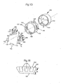
- the ring includes a ring body 300 having an opening 370 for receiving a finger therethrough.
- the ring body 300 includes an outer surface 302 and an inner surface 304.
- the inner and outer surfaces 302, 304 have a generally circular or arcuate shape and form a generally cylindrical body.
- the inner surface 304 may include a channel or grooved region 308 into which the movable segment 330 may be placed.
- the outer surface 302 may include any manner of design or decoration.
- the ring body 300 may be formed of any of a variety of materials and may be formed in any of a variety of sizes.
- the adjustable ring further includes a locking ring 310 that is coupled to the ring portion 300.
- a locking ring 310 that is coupled to the ring portion 300.
- the locking ring 310 includes an outer surface 305 and an inner surface 306.
- the outer surface 305 of the locking ring 310 cooperates with the inner surface 304 of the ring body 300.
- the locking ring 310 is press fit into the ring body 300. While the locking rings 310 have been described as separate components, they may alternatively be pre-formed into the ring body 300 itself.
- the use of a locking ring 310 in conjunction with the ring body 300 helps provide a retaining mechanism for the movable segment(s) 330 as is described further below.
- the adjustable ring according to this third embodiment further includes one or more movable segments 330.
- the movable segments 330 include an outer surface 334 and an inner surface 332, both of which are preferably arcuate shaped.
- the movable segments 330 preferably include an overlap region 336 such that the placement of one movable segment 330 next to another results in a smooth seam 342 being formed at the inner surfaces 332 of the movable segments 330. In this way, a smooth, comfortable, generally continuous inner ring surface is provided to the user.
- the outer surface 334 of the movable segments 330 include a channel or grooved region 338 for receiving and housing a spring element 350.
- the adjustable ring according to this third embodiment further includes one or more spring elements 350.
- spring elements 350 Preferably, three spring elements are used, one coupled to each of the three movable segments 330. While any of a variety of types of springs (e.g., compression springs as shown in FIGS 3D and 3G ) may be used for the spring element 350, flat or wire springs are preferable.
- the spring elements 350 are preferably uncompressed and in their natural state such that the movable segments 330 protrude into the ring opening 370 to a first position 340 a, b, c to create a reduced open area for the user's finger.
- the finger compresses the spring elements 350 and the movable segments 330 move outwardly to a second position thus creating a expanded opening to fit over the user's finger.
- the compression and expansion of the spring elements 350 provide for an adjustable size opening for the user's finger.
- the movable segments 330 can move among a plurality of positions, thus accommodating a range of openings (i.e., ring sizes).
- FIGS. 4A-4G A fourth embodiment of an adjustable ring is illustrated in FIGS. 4A-4G .
- This embodiment is similar in most respect to the third embodiment described above. The main difference is with regard to the movable segments 430.
- the fourth embodiment is preferably used in conjunction with a ring body 400 having a larger width (w), while the third embodiment is more preferably used in conjunction with a ring body 300 having a smaller width (w).
- the operation of this fourth embodiment is generally the same as that of the third embodiment.
- the adjustable ring according to the fourth embodiment preferably includes a ring portion 400 having an outer surface 402 and an inner surface 404, and preferably a groove or channel 408 in the inner surface 404.
- the adjustable ring also preferably includes two locking rings 410, one on each side of the ring body 400, which are preferably press fit into the ring body 400 to help retain the movable segments 430 in the ring.
- the adjustable ring further includes one or more spring elements 450, which, as contrasted with the third embodiment, are preferably coil or compression springs. According to one aspect, a plurality of spring elements 450 are used in connection with each of a plurality of movable segments 430.
- the fourth embodiment includes a movable segment 430 having an outer surface 434, an inner surface 432, and preferably an overlap region 436. In this way, it is similar to the movable segment 330 described above in connection with the third embodiment .
- the movable segments 430 are used, although any number can be chosen as desired.
- the movable segments 430 of the fourth embodiment preferably include one or more nesting regions 438 in the outer surfaces 434 of the movable segments 430.
- each movable segment 430 includes three nesting regions 438.
- each nest 438 preferably extend partially, but not fully, through the body of the movable segment 430, so that the spring elements 450 can be seated within the movable segment 430.
- each nest 438 houses a single corresponding spring element 450,
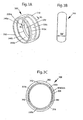
- FIG. 5A is an exploded perspective view of the ring.
- the ring includes a ring body 500 having an opening 570 for receiving a finger therethrough.
- the ring body 500 includes an outer surface 502 and an inner surface 504.
- the outer surface 502 may include any manner of design or decoration.
- the ring body 500 may be formed of any of a variety of materials and may be formed in any of a variety of sizes.
- the ring body 500 may include a channel or grooved region 508 into which movable segments 530 may be placed. The channel 508 is located between the inner surface 504 and the outer surface 502 of the ring body 500.
- the adjustable ring according to this fifth embodiment further includes one or more movable segments 530.
- movable segments 530 Preferably, three movable segments are used.
- Each movable segment 530 includes an outer surface 534 and an inner surface 536, both of which are preferably arcuate shaped. The width of the inner surface 536 is less than the width of the outer surface 534.
- Each movable segment 530 further includes tabs 532 at both ends. The tabs 532 are located on the movable segments 530 adjacent to the outer surface 534. The width of the tabs 532 is greater than the width of the main body of the movable segments 530.
- the adjustable ring according to this fifth embodiment further includes one or more spring elements 560.
- spring elements 560 Preferably, three spring elements are used, one located between each of the three movable segments 530 and the ring body 500.
- the outer surface 534 of each movable segment includes a slot, channel or groove 550 into which a spring element 560 can be placed. While any of a variety of types of springs may be used for the spring element 560, flat or wire springs are preferable.
- FIG. 5B is a side elevational view of the fifth embodiment of the adjustable ring shown in FIG. 5A .
- the ring body 500 and the opening for receiving a finger 570 are illustrated.
- FIG. 5C is a view of the ring body 500 taken along the line 5c-5c of FIG. 5B .
- the inner surface 504 includes a channel opening 512 which provides access into the channel 508 from the inner surface 504.
- the width of the channel opening 512 is generally smaller than the width of the channel 508.
- the width of the inner surface 536 of the movable segments 530 is smaller than the width of the channel opening 512
- the width of the tabs 532 is larger than the width of the channel opening 512 and smaller than the width of the channel 508.
- the tabs 532 can be inserted into the channel 508 via the channel access region 514. Once the tabs 532 have been inserted into the channel 508, the rest of the movable segment 530 can be inserted into the channel 508 by manually sliding the movable segment 530 into the channel 508 through the channel access region 514.
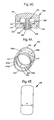
- FIG. 5D is a cross sectional view of the ring taken through lines 5d-5d of FIG. 5B .
- the inner surface 504 of the ring and the movable segment 530 are shown, with the movable segment 530 being located within the channel 508.
- the inner surface 536 of the movable segment 530 is shown protruding through the channel opening 512, while the tabs 532 are confined within the channel 508 behind the channel opening 512.
- FIG. 5E is a side cross-sectional view of the ring, fully assembled, with the movable segments 530 located within the channel 508.
- the spring elements 560 are located between the movable segments and the ring body 500. In use, and before the user places the adjustable ring on the user's finger, the spring elements 560 are preferably uncompressed and in their natural state such that the movable segments 530 protrude into the channel opening 512 to a first position 540 a, b, c to create a reduced open area for the user's finger. Alternatively, the spring elements 560 may always be in some state of compression. The amount of protrusion of the movable segments 530 into the ring opening is selected to create the desired amount of variation in the size of the ring opening.
- FIG. 5F is a side cross-sectional view of the ring, fully assembled, with the spring elements 560 compressed.
- the spring elements 560 are located within the groove 550 on the outer surface 534 of the movable segments 530, and, therefore, cannot be seen in this cross-sectional view.
- the finger compresses the spring elements 560 and the movable segments 530 move outwardly in a radial direction to a second position 550 a, b, c, thus creating an expanded opening to fit over the user's finger.
- the compression and expansion of the spring elements 560 provide for an adjustable size opening for the user's finger.
- the movable segments 530 can move among a plurality of positions, thus accommodating a range of openings (i.e., ring sizes).
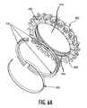
- the jewelry includes a ring shaped frame 600 having an opening 670 for receiving a finger or other appendage of the wearer therethrough.
- the ring shaped frame 600 includes an outer surface 602 and an inner surface 604, and defines a generally a ring shape.
- the outer surface 602 may include a number of jewel or stone mountings 640 or any manner of design or decoration.
- the present embodiment is not limited in that aspect.
- the ring shaped frame 600 may be formed of any of a variety of materials and may be formed in any of a variety of sizes.
- the ring shaped frame 600 may include a channel or grooved region 608 into which movable segments 630 may be placed.
- the channel 608 is located between the inner surface 604 and the outer surface 602 of the ring shaped frame 600.
- the channel 608 extends all the way around the inner surface 604, and has a depth extending from the inner surface 604 towards the outer surface 602 and a width defined by the two opposing side walls of the channel extending along the circumference of the ring shaped frame between the inner surface 604 and the outer surface 602.
- the adjustable jewelry includes one or more movable segments 630. While the present example is shown with three movable segments, any number of movable segments may be used.
- Each movable segment 630 comprises an elongated member bent into a curved or arcuate shape having a curvature that generally conforms to the curvature of the inner surface of the ring shaped frame 600 so that when the movable segments are arranged together in an end-to-end formation, the movable segments together define a generally a ring shape conforming substantially to the ring defined by the ring shaped frame 600, and in one aspect of the embodiment may even be substantially concentric with the ring defined by the ring shaped frame 600.
- Each movable segment includes an outer surface 634 and an inner surface 636.
- each movable segment 630 may include flange sections 632 towards the outer surface 634 and, preferably, at both distal ends. The widths of the flanges 632 are greater than the width of the main body 635 of the movable segments 630.
- the adjustable jewelry further includes one or more spring elements 660. While any of a variety of types of springs may be used, preferably, as shown in FIG. 6A , one "C" spring, which can be either a flat or wire spring, may be used.
- the outer surface 634 of each movable segment includes a slot, channel or groove 644 and 645 into which the spring element 660 can be placed.
- the channel 645 is an open channel into which an uninterrupted section of the spring element 660 may be received.
- the channels 644 are provided in at least two of the moving segments, and are each closed at one end at least partially by the spring stop 646. Each of the spring stops 646 receives and holds an end of the spring element 660 and prevents the spring element 660 from being disengaged from the movable segments 630.
- the inner surface 604 includes a channel opening 612 which provides access into the channel 608 from the inner surface 604.
- the width of the channel opening 612 is generally smaller than the width of the channel 608.
- the width of the inner surface 636 of the movable segments 630 is smaller than the width of the channel opening 612, and the width of the flanges 632 is larger than the width of the channel opening 612 and smaller than or substantially same as the width of the channel 608.
- a channel access region 614 having an enlarged opening width relative to the rest of the channel opening 612, such that the flanges 632 can be inserted into the channel 608 via the channel access region 614.
- one end of the spring member 660 is placed into a spring stop 646 provided on one end of a moving segment 630, the flange located at the same end of the moving segment 630 is then inserted into the channel 608 through the channel access region 614.
- the rest of the movable segment 630 can be inserted into the channel 608 by manually sliding the movable segment 630 into the channel 608 through the channel access region 614.
- the movable segment(s) with an open channel 645 can then be placed into the channel 608 in a similar manner while the remaining portions of the spring member 660 is placed within the open channel 645.
- the last movable segment with a spring stop 646 can then be inserted into the channel 608 by inserting the flange 632 on the opposite end to the end with the spring stop 646 with the remaining end of the spring member 660 engaged in the spring stop 646.
- FIG, 6C is a cross sectional view of the ring taken through lines 6c-6c of FIG. 6B .
- the inner surface 604 of the ring shaped frame and the movable segment(s) 630 are shown, with the movable segment 630 being located within the channel 608.
- the inner surface 636 of the movable segment 630 is shown protruding through the channel opening 612, while the flanges 632 are confined within the channel 608 behind the channel opening 612.
- the spring element 660 is preferably in its natural "C" shape such that the movable segments 630 protrude into the channel opening 612 to a fully extended position to define a reduced size for the jewelry.
- the spring element 660 may always be in some state of compression. The amount of protrusion of the movable segment 660 into the opening 670 is selected to create the desired amount of variation in the size of the ring opening.
- the movable segments 630 retract into the channel opening 612, expanding the spring element 660 out of its natural shape to have a wider opening of the "C", and defining a larger opening 670 to accommodate a larger appendage of the user.
- the expansion and retraction of the spring element 660 provide for an adjustable size opening 670 for the user's appendage.
- the movable segments 630 can move among a plurality of positions, thus accommodating a range of openings (i.e., a range of ring or bracelet sizes).
- the flange portions 632 have a sufficiently small width in comparison to the width of the channel 608 so as to not interfere with the movement of the movable segments 630 within the channel 608.
- the flange portions 632 can be made to have substantially the same width as the width of the channel 608 so that the flanges are in sliding contact with the side walls of the channel 608. The amount of resulting frictional force between a flange and the side wall can be adjusted empirically taking into account, for example, the material(s) of the ring shaped frame 600 and the movable segments 630, the spring constant of the spring element 660, the contact surface area between the flange and the channel wall, and the like.
- the amount of frictional force is selected to allow the movable segments 630 to move yet the frictional force sufficiently oppose the biasing force of the spring element 660 so as to alleviate some of, or to reduce, the constant pressure being applied to the skin of the wearer so that it does not become overly excessive.
- the amount of the frictional force may be selected to sufficiently oppose the bias force of the spring element 660 such that once a movable segment becomes stationary at a position between a fully extended position (i.e., defining the smallest size of the opening 670) and a fully retracted position (i.e., defining the largest opening 670), the bias force from the spring element 660 is sufficiently overcome so that the movable segment can remain in that position indefinitely until an external force disrupts the balance between the two opposing forces to dislodge the flange from the side wall of the channel, and to cause the bias force of the spring element 660 to move the movable segment.
- the jewelry according to this aspect of the embodiment can be made to ''remember"' the size adjusted to closely match the size of the wearer.
- the outside surface of the ring body or the ring shaped frame may be plain or it may be decorated in any desired way.
- the outer perimeter of the ring shaped frame can be adorned with one or more mounting sections 640 for mounting one or more jeweled stones, such as a diamond, as is known in the art.
- the outer surface of the ring portion have been described herein to be generally arc shaped, any shaped surfaces may be utilized within the present invention. For example, a flat shaped outer surface is often preferable in rings for men and where stones are to be mounted on top of the ring.
- the adjustable jewelry of the present invention may be created in any of a variety of sizes and may be caused to adjust within various size ranges.
- an adjustable size finger receiving opening that accommodates sizes within a range of 1 mm or approximately one ring size (most individuals would typically not have a need for larger size adjustments)
- the adjustment mechanism of the present invention may be modified to accommodate smaller (i.e., half size) or larger (i.e., two sizes) adjustment ranges.
- the present invention has been generally described herein with respect to rings worn over a wearer's finger, the present invention applies equally to other types of jewelry, such as bracelets, where similar adjustments would be applicable and beneficial to a wearer.
- the disclosed adjustment mechanisms could be utilized in conjunction with a bracelet to provide a way for adjusting the diameter of the interior wrist-receiving opening of the bracelet.
- a wearer can place the bracelet over the hand and onto the wrist without having to open the bracelet, stretch the bracelet, or utilize a bracelet which is ultimately too large for the wearer's wrist.
- the outside portion of the bracelet could then be decorated or designed in any desired way, all within the scope of the present invention.
Landscapes
- Adornments (AREA)
Claims (8)
- Article de bijouterie, comprenant :un tour de forme annulaire (600) définissant une première forme annulaire d'une première taille ;une pluralité de segments d'ajustement de taille (630) montés de manière mobile sur ledit tour annulaire (600), chacun de ladite pluralité de segments d'ajustement de taille (630) étant apte à se déplacer dans un sens radial par rapport audit tour annulaire de manière à ce que ladite pluralité de segments d'ajustement de taille définissent ensemble une seconde forme annulaire d"une seconde taille, ladite seconde forme annulaire étant sensiblement concentrique par rapport à ladite première forme annulaire ; etun élément élastique (660) conférant une inclinaison à chacun de ladite pluralité de segments d'ajustement de taille (630) vers un centre radial dudit tour de forme annulaire (600), caractérisé en ce que :l'élément élastique (660) comprend un anneau en C ; etchacun de ladite pluralité de segments d'ajustement de taille (630) a une gorge continue (644, 645) pratiquée sur une surface de son périmètre extérieur (634) et destinée à recevoir une section ininterrompue dudit élément élastique (660), deux de ladite pluralité de segments d'ajustement de taille étant des segments terminaux ayant chacun un arrêt de ressort (646) formé sur une extrémité de ladite gorge (644) pour recevoir une extrémité dudit élément élastique (660).
- Article de bijouterie selon la revendication 1, dans lequel ledit tour de forme annulaire comprend une surface circonférentielle interne et une surface circonférentielle externe, ledit tour de forme annulaire comprenant un canal (608) de profondeur prédéterminée dont les parois latérales opposées s'étendent de ladite surface circonférentielle interne à ladite surface circonférentielle externe, ladite surface circonférentielle interne définissant ladite première forme annulaire, au moins une section de chacun de ladite pluralité de segments d'ajustement de taille étant disposée de manière mobile dans ledit canal et l'élément élastique étant disposé dans ledit canal.
- Article de bijouterie selon la revendication 2, dans lequel :chacun de ladite pluralité de segments d'ajustement de taille (630) a une forme arquée suivant d'une manière générale une courbure de ladite surface circonférentielle interne dudit tour de forme annulaire de manière à ce que, lorsque ladite pluralité de segments d'ajustement de taille sont disposés bout à bout, ladite pluralité de segments d'ajustement de taille forment ensemble un tour annulaire global sensiblement concentrique à ladite première forme annulaire.
- Article de bijouterie selon la revendication 2, dans lequel :ledit canal (608) a une largeur de canal définie entre lesdites deux parois latérales opposées, ledit canal ayant en outre une ouverture de canal plus étroite (612) ayant une première largeur plus étroite et une ouverture de canal plus large (614) ayant une seconde largeur plus importante que ladite première largeur etdans lequel chacun de ladite pluralité de segments d'ajustement de taille (630) a une section de surface interne (636) ayant une troisième largeur plus étroite que ladite première largeur et une section de rebord plus large (632) ayant une quatrième largeur qui est plus étroite que ladite seconde largeur et plus importante que ladite première largeur, de sorte que ladite section de rebord (632) est apte à rentrer dans ledit canal (608) par ladite ouverture de canal plus large (614) et que, lorsque ladite section de rebord (632) est positionnée dans ledit canal (608) au niveau de ladite ouverture plus étroite (612), ladite section de rebord (632) est empêchée de quitter ledit canal par ladite ouverture plus étroite (612) alors que ladite section de surface interne (636) peut saillir à travers ladite ouverture plus étroite (632).
- Article de bijouterie selon la revendication 2, dans lequel ladite pluralité de segments d'ajustement de taille (630) comprend :au moins un segment un segment intermédiaire pourvu d'une gorge continue (645) pour recevoir une section ininterrompue dudit élément élastique mais pas un arrêt de ressort (646).
- Article de bijouterie selon la revendication 2, dans lequel
au moins un de ladite pluralité de segments d'ajustement de taille (630) a une section de contact qui est en contact coulissant avec au moins une desdites deux parois latérales dudit canal avec une friction suffisante entre eux pour s'opposer à au moins une partie de ladite inclinaison créée par ledit élément élastique. - Article de bijouterie selon la revendication 6, dans lequel chacun de ladite pluralité de segments d'ajustement de taille (630) est apte à se déplacer dans une plage entre une position entièrement déployée et une position entièrement rétractée, ladite seconde taille étant la plus petite lorsque chacun de ladite pluralité de segments d'ajustement de taille est dans ladite position entièrement déployée et étant la plus grande lorsque chacun de ladite pluralité de segments d'ajustement de taille est dans ladite position entièrement rétractée, et dans lequel :ledit contact coulissant résultant en un niveau de friction tel que ledit au moins un de ladite pluralité de segments d'ajustement de taille reste indéfiniment à une position située entre ladite position entièrement déployée et ladite position entièrement rétractée, ladite position n'étant ni ladite position entièrement déployée, ni ladite position entièrement rétractée.
- Article de bijouterie selon l'une quelconque des revendications 1 à 7, dans lequel
ledit tour de forme annulaire a une taille et une forme fixes.
Applications Claiming Priority (1)
| Application Number | Priority Date | Filing Date | Title |
|---|---|---|---|
| PCT/US2007/076980 WO2009029093A1 (fr) | 2007-08-28 | 2007-08-28 | Bijou de taille réglable |
Publications (3)
| Publication Number | Publication Date |
|---|---|
| EP2200472A1 EP2200472A1 (fr) | 2010-06-30 |
| EP2200472A4 EP2200472A4 (fr) | 2012-05-09 |
| EP2200472B1 true EP2200472B1 (fr) | 2013-07-17 |
Family
ID=40387597
Family Applications (1)
| Application Number | Title | Priority Date | Filing Date |
|---|---|---|---|
| EP07841459.6A Not-in-force EP2200472B1 (fr) | 2007-08-28 | 2007-08-28 | Bijou de taille réglable |
Country Status (4)
| Country | Link |
|---|---|
| EP (1) | EP2200472B1 (fr) |
| CN (1) | CN101795595B (fr) |
| HK (1) | HK1145614A1 (fr) |
| WO (1) | WO2009029093A1 (fr) |
Families Citing this family (8)
| Publication number | Priority date | Publication date | Assignee | Title |
|---|---|---|---|---|
| TR200903654A2 (tr) * | 2009-05-11 | 2010-03-22 | Akdemi̇r Edi̇p | Çoklu ölçü ayarlanabililik özelliğine sahip bir yüzük ve bu işlem için bir metot |
| US9763500B2 (en) * | 2012-07-20 | 2017-09-19 | Cinque S.R.L. | Ring |
| GB201322291D0 (en) * | 2013-12-17 | 2014-01-29 | Win Shwezin K T | BangleBand |
| CN104665132B (zh) * | 2015-03-22 | 2016-03-23 | 深圳市中盛珠宝首饰有限公司 | 可调手寸的戒指 |
| CN107007274A (zh) * | 2017-04-24 | 2017-08-04 | 苏州国科智策智能科技有限公司 | 压力可控的分体式智能健康指环 |
| CN108030199B (zh) * | 2017-12-26 | 2020-02-21 | 安徽省东乾食品有限公司 | 一种用于脱水果蔬加工的智能手环 |
| FR3080747B1 (fr) * | 2018-05-03 | 2020-04-24 | Cartier International Ag | Bague joailliere ajustable comprenant des moyens de guidage |
| IT201800006724A1 (it) * | 2018-06-27 | 2019-12-27 | Oggetto anulare da indossare |
Family Cites Families (9)
| Publication number | Priority date | Publication date | Assignee | Title |
|---|---|---|---|---|
| DE1140768B (de) * | 1961-07-12 | 1962-12-06 | Moriz Hausch A G | Fingerring mit verstellbarer Weite |
| FR1582788A (fr) * | 1968-01-12 | 1969-10-10 | ||
| US4471634A (en) * | 1983-01-26 | 1984-09-18 | Sol Kaplan | Plural section ring sizer |
| US5412956A (en) * | 1994-01-19 | 1995-05-09 | Davida Enterprises, Inc. | Variable sized hinged ring |
| US6003334A (en) * | 1994-07-29 | 1999-12-21 | Miller; Bryan J. | Finger ring size adjusting device and method |
| US5943882A (en) * | 1998-11-05 | 1999-08-31 | Erb; Jean-Francois Albert | Self sizing ring |
| US6748764B1 (en) * | 2000-09-20 | 2004-06-15 | Thomas Bruce Roemer | Self-adjusting ring size reducer |
| DE202004015817U1 (de) * | 2004-10-09 | 2005-01-05 | Charareh, Lavinia | Vorrichtung zur stufenlosen Größenregulierung und Verschlußfunktion für Armreifen/Ringe |
| US7409836B2 (en) * | 2005-01-21 | 2008-08-12 | Hearts On Fire Company | Adjustable size ring |
-
2007
- 2007-08-28 CN CN200780100448.9A patent/CN101795595B/zh not_active Expired - Fee Related
- 2007-08-28 EP EP07841459.6A patent/EP2200472B1/fr not_active Not-in-force
- 2007-08-28 WO PCT/US2007/076980 patent/WO2009029093A1/fr active Application Filing
-
2010
- 2010-12-23 HK HK10112091.1A patent/HK1145614A1/xx not_active IP Right Cessation
Also Published As
| Publication number | Publication date |
|---|---|
| EP2200472A1 (fr) | 2010-06-30 |
| CN101795595B (zh) | 2013-06-12 |
| HK1145614A1 (en) | 2011-04-29 |
| WO2009029093A1 (fr) | 2009-03-05 |
| EP2200472A4 (fr) | 2012-05-09 |
| CN101795595A (zh) | 2010-08-04 |
Similar Documents
| Publication | Publication Date | Title |
|---|---|---|
| US7845191B2 (en) | Adjustable sized jewelry | |
| US7861554B2 (en) | Adjustable sized jewelry | |
| US7409836B2 (en) | Adjustable size ring | |
| EP2200472B1 (fr) | Bijou de taille réglable | |
| US6484535B2 (en) | Adjustable jewelry assembly | |
| US7150164B2 (en) | Finger ring fit adjuster | |
| US5727399A (en) | Ring insert assembly | |
| US5951193A (en) | Mechanism for connecting ornamental parts of wrist watch | |
| EP1000560B1 (fr) | Anneau auto-ajustable | |
| WO1997034511A1 (fr) | Bague a charniere | |
| TWI243037B (en) | Bracelet provided with a clasp | |
| US5606873A (en) | Finger ring | |
| US20070251269A1 (en) | Adjustable Jewelry Assembly | |
| US4753087A (en) | Adjustable ring structure | |
| US7523556B2 (en) | Ring expansion method and device | |
| US2032557A (en) | Wrist watch strap, band, or bracelet | |
| EP1358814A1 (fr) | Anneau réglable d'une seule pièce | |
| JPH10165210A (ja) | 指 輪 | |
| JP3018255U (ja) | 調節式装飾バンド、指輪及び腕輪 | |
| JP3026157B2 (ja) | 耳飾り | |
| GB2296648A (en) | Improved closure means | |
| TH79897A (th) | เครื่องประดับอัญมณีที่ปรับขนาดได้ | |
| TH52768B (th) | เครื่องประดับอัญมณีที่ปรับขนาดได้ | |
| JP2003310315A (ja) | ピアス |
Legal Events
| Date | Code | Title | Description |
|---|---|---|---|
| PUAI | Public reference made under article 153(3) epc to a published international application that has entered the european phase |
Free format text: ORIGINAL CODE: 0009012 |
|
| 17P | Request for examination filed |
Effective date: 20100325 |
|
| AK | Designated contracting states |
Kind code of ref document: A1 Designated state(s): AT BE BG CH CY CZ DE DK EE ES FI FR GB GR HU IE IS IT LI LT LU LV MC MT NL PL PT RO SE SI SK TR |
|
| AX | Request for extension of the european patent |
Extension state: AL BA HR MK RS |
|
| DAX | Request for extension of the european patent (deleted) | ||
| A4 | Supplementary search report drawn up and despatched |
Effective date: 20120411 |
|
| RIC1 | Information provided on ipc code assigned before grant |
Ipc: A44C 9/02 20060101AFI20120403BHEP |
|
| GRAP | Despatch of communication of intention to grant a patent |
Free format text: ORIGINAL CODE: EPIDOSNIGR1 |
|
| GRAS | Grant fee paid |
Free format text: ORIGINAL CODE: EPIDOSNIGR3 |
|
| GRAA | (expected) grant |
Free format text: ORIGINAL CODE: 0009210 |
|
| AK | Designated contracting states |
Kind code of ref document: B1 Designated state(s): AT BE BG CH CY CZ DE DK EE ES FI FR GB GR HU IE IS IT LI LT LU LV MC MT NL PL PT RO SE SI SK TR |
|
| REG | Reference to a national code |
Ref country code: GB Ref legal event code: FG4D |
|
| REG | Reference to a national code |
Ref country code: CH Ref legal event code: EP |
|
| REG | Reference to a national code |
Ref country code: IE Ref legal event code: FG4D |
|
| REG | Reference to a national code |
Ref country code: AT Ref legal event code: REF Ref document number: 621628 Country of ref document: AT Kind code of ref document: T Effective date: 20130815 |
|
| REG | Reference to a national code |
Ref country code: DE Ref legal event code: R096 Ref document number: 602007031751 Country of ref document: DE Effective date: 20130912 |
|
| REG | Reference to a national code |
Ref country code: CH Ref legal event code: NV Representative=s name: MEYER AND KOLLEGEN, CH |
|
| REG | Reference to a national code |
Ref country code: AT Ref legal event code: MK05 Ref document number: 621628 Country of ref document: AT Kind code of ref document: T Effective date: 20130717 |
|
| REG | Reference to a national code |
Ref country code: NL Ref legal event code: VDEP Effective date: 20130717 |
|
| REG | Reference to a national code |
Ref country code: LT Ref legal event code: MG4D |
|
| PG25 | Lapsed in a contracting state [announced via postgrant information from national office to epo] |
Ref country code: LT Free format text: LAPSE BECAUSE OF FAILURE TO SUBMIT A TRANSLATION OF THE DESCRIPTION OR TO PAY THE FEE WITHIN THE PRESCRIBED TIME-LIMIT Effective date: 20130717 Ref country code: BE Free format text: LAPSE BECAUSE OF FAILURE TO SUBMIT A TRANSLATION OF THE DESCRIPTION OR TO PAY THE FEE WITHIN THE PRESCRIBED TIME-LIMIT Effective date: 20130717 Ref country code: PT Free format text: LAPSE BECAUSE OF FAILURE TO SUBMIT A TRANSLATION OF THE DESCRIPTION OR TO PAY THE FEE WITHIN THE PRESCRIBED TIME-LIMIT Effective date: 20131118 Ref country code: AT Free format text: LAPSE BECAUSE OF FAILURE TO SUBMIT A TRANSLATION OF THE DESCRIPTION OR TO PAY THE FEE WITHIN THE PRESCRIBED TIME-LIMIT Effective date: 20130717 Ref country code: CY Free format text: LAPSE BECAUSE OF FAILURE TO SUBMIT A TRANSLATION OF THE DESCRIPTION OR TO PAY THE FEE WITHIN THE PRESCRIBED TIME-LIMIT Effective date: 20130828 Ref country code: IS Free format text: LAPSE BECAUSE OF FAILURE TO SUBMIT A TRANSLATION OF THE DESCRIPTION OR TO PAY THE FEE WITHIN THE PRESCRIBED TIME-LIMIT Effective date: 20131117 Ref country code: SE Free format text: LAPSE BECAUSE OF FAILURE TO SUBMIT A TRANSLATION OF THE DESCRIPTION OR TO PAY THE FEE WITHIN THE PRESCRIBED TIME-LIMIT Effective date: 20130717 |
|
| PG25 | Lapsed in a contracting state [announced via postgrant information from national office to epo] |
Ref country code: NL Free format text: LAPSE BECAUSE OF FAILURE TO SUBMIT A TRANSLATION OF THE DESCRIPTION OR TO PAY THE FEE WITHIN THE PRESCRIBED TIME-LIMIT Effective date: 20130717 Ref country code: ES Free format text: LAPSE BECAUSE OF FAILURE TO SUBMIT A TRANSLATION OF THE DESCRIPTION OR TO PAY THE FEE WITHIN THE PRESCRIBED TIME-LIMIT Effective date: 20131028 Ref country code: FI Free format text: LAPSE BECAUSE OF FAILURE TO SUBMIT A TRANSLATION OF THE DESCRIPTION OR TO PAY THE FEE WITHIN THE PRESCRIBED TIME-LIMIT Effective date: 20130717 Ref country code: LV Free format text: LAPSE BECAUSE OF FAILURE TO SUBMIT A TRANSLATION OF THE DESCRIPTION OR TO PAY THE FEE WITHIN THE PRESCRIBED TIME-LIMIT Effective date: 20130717 Ref country code: PL Free format text: LAPSE BECAUSE OF FAILURE TO SUBMIT A TRANSLATION OF THE DESCRIPTION OR TO PAY THE FEE WITHIN THE PRESCRIBED TIME-LIMIT Effective date: 20130717 Ref country code: GR Free format text: LAPSE BECAUSE OF FAILURE TO SUBMIT A TRANSLATION OF THE DESCRIPTION OR TO PAY THE FEE WITHIN THE PRESCRIBED TIME-LIMIT Effective date: 20131018 Ref country code: SI Free format text: LAPSE BECAUSE OF FAILURE TO SUBMIT A TRANSLATION OF THE DESCRIPTION OR TO PAY THE FEE WITHIN THE PRESCRIBED TIME-LIMIT Effective date: 20130717 |
|
| PG25 | Lapsed in a contracting state [announced via postgrant information from national office to epo] |
Ref country code: CY Free format text: LAPSE BECAUSE OF FAILURE TO SUBMIT A TRANSLATION OF THE DESCRIPTION OR TO PAY THE FEE WITHIN THE PRESCRIBED TIME-LIMIT Effective date: 20130717 |
|
| PG25 | Lapsed in a contracting state [announced via postgrant information from national office to epo] |
Ref country code: EE Free format text: LAPSE BECAUSE OF FAILURE TO SUBMIT A TRANSLATION OF THE DESCRIPTION OR TO PAY THE FEE WITHIN THE PRESCRIBED TIME-LIMIT Effective date: 20130717 Ref country code: SK Free format text: LAPSE BECAUSE OF FAILURE TO SUBMIT A TRANSLATION OF THE DESCRIPTION OR TO PAY THE FEE WITHIN THE PRESCRIBED TIME-LIMIT Effective date: 20130717 Ref country code: CZ Free format text: LAPSE BECAUSE OF FAILURE TO SUBMIT A TRANSLATION OF THE DESCRIPTION OR TO PAY THE FEE WITHIN THE PRESCRIBED TIME-LIMIT Effective date: 20130717 Ref country code: DK Free format text: LAPSE BECAUSE OF FAILURE TO SUBMIT A TRANSLATION OF THE DESCRIPTION OR TO PAY THE FEE WITHIN THE PRESCRIBED TIME-LIMIT Effective date: 20130717 Ref country code: MC Free format text: LAPSE BECAUSE OF FAILURE TO SUBMIT A TRANSLATION OF THE DESCRIPTION OR TO PAY THE FEE WITHIN THE PRESCRIBED TIME-LIMIT Effective date: 20130717 Ref country code: RO Free format text: LAPSE BECAUSE OF FAILURE TO SUBMIT A TRANSLATION OF THE DESCRIPTION OR TO PAY THE FEE WITHIN THE PRESCRIBED TIME-LIMIT Effective date: 20130717 |
|
| REG | Reference to a national code |
Ref country code: IE Ref legal event code: MM4A |
|
| PLBE | No opposition filed within time limit |
Free format text: ORIGINAL CODE: 0009261 |
|
| STAA | Information on the status of an ep patent application or granted ep patent |
Free format text: STATUS: NO OPPOSITION FILED WITHIN TIME LIMIT |
|
| PG25 | Lapsed in a contracting state [announced via postgrant information from national office to epo] |
Ref country code: IT Free format text: LAPSE BECAUSE OF FAILURE TO SUBMIT A TRANSLATION OF THE DESCRIPTION OR TO PAY THE FEE WITHIN THE PRESCRIBED TIME-LIMIT Effective date: 20130717 |
|
| 26N | No opposition filed |
Effective date: 20140422 |
|
| PG25 | Lapsed in a contracting state [announced via postgrant information from national office to epo] |
Ref country code: IE Free format text: LAPSE BECAUSE OF NON-PAYMENT OF DUE FEES Effective date: 20130828 |
|
| REG | Reference to a national code |
Ref country code: DE Ref legal event code: R097 Ref document number: 602007031751 Country of ref document: DE Effective date: 20140422 |
|
| PG25 | Lapsed in a contracting state [announced via postgrant information from national office to epo] |
Ref country code: TR Free format text: LAPSE BECAUSE OF FAILURE TO SUBMIT A TRANSLATION OF THE DESCRIPTION OR TO PAY THE FEE WITHIN THE PRESCRIBED TIME-LIMIT Effective date: 20130717 Ref country code: MT Free format text: LAPSE BECAUSE OF FAILURE TO SUBMIT A TRANSLATION OF THE DESCRIPTION OR TO PAY THE FEE WITHIN THE PRESCRIBED TIME-LIMIT Effective date: 20130717 |
|
| PG25 | Lapsed in a contracting state [announced via postgrant information from national office to epo] |
Ref country code: BG Free format text: LAPSE BECAUSE OF FAILURE TO SUBMIT A TRANSLATION OF THE DESCRIPTION OR TO PAY THE FEE WITHIN THE PRESCRIBED TIME-LIMIT Effective date: 20130717 Ref country code: HU Free format text: LAPSE BECAUSE OF FAILURE TO SUBMIT A TRANSLATION OF THE DESCRIPTION OR TO PAY THE FEE WITHIN THE PRESCRIBED TIME-LIMIT; INVALID AB INITIO Effective date: 20070828 Ref country code: LU Free format text: LAPSE BECAUSE OF NON-PAYMENT OF DUE FEES Effective date: 20130828 |
|
| REG | Reference to a national code |
Ref country code: FR Ref legal event code: PLFP Year of fee payment: 10 |
|
| PGFP | Annual fee paid to national office [announced via postgrant information from national office to epo] |
Ref country code: DE Payment date: 20160824 Year of fee payment: 10 Ref country code: GB Payment date: 20160825 Year of fee payment: 10 Ref country code: CH Payment date: 20160830 Year of fee payment: 10 |
|
| PGFP | Annual fee paid to national office [announced via postgrant information from national office to epo] |
Ref country code: FR Payment date: 20160824 Year of fee payment: 10 |
|
| REG | Reference to a national code |
Ref country code: DE Ref legal event code: R119 Ref document number: 602007031751 Country of ref document: DE |
|
| REG | Reference to a national code |
Ref country code: CH Ref legal event code: PL |
|
| GBPC | Gb: european patent ceased through non-payment of renewal fee |
Effective date: 20170828 |
|
| PG25 | Lapsed in a contracting state [announced via postgrant information from national office to epo] |
Ref country code: CH Free format text: LAPSE BECAUSE OF NON-PAYMENT OF DUE FEES Effective date: 20170831 Ref country code: LI Free format text: LAPSE BECAUSE OF NON-PAYMENT OF DUE FEES Effective date: 20170831 |
|
| REG | Reference to a national code |
Ref country code: FR Ref legal event code: ST Effective date: 20180430 |
|
| PG25 | Lapsed in a contracting state [announced via postgrant information from national office to epo] |
Ref country code: GB Free format text: LAPSE BECAUSE OF NON-PAYMENT OF DUE FEES Effective date: 20170828 Ref country code: DE Free format text: LAPSE BECAUSE OF NON-PAYMENT OF DUE FEES Effective date: 20180301 |
|
| PG25 | Lapsed in a contracting state [announced via postgrant information from national office to epo] |
Ref country code: FR Free format text: LAPSE BECAUSE OF NON-PAYMENT OF DUE FEES Effective date: 20170831 |