EP2199722A2 - Refroidisseur pour gaz d'échappement - Google Patents
Refroidisseur pour gaz d'échappement Download PDFInfo
- Publication number
- EP2199722A2 EP2199722A2 EP09177831A EP09177831A EP2199722A2 EP 2199722 A2 EP2199722 A2 EP 2199722A2 EP 09177831 A EP09177831 A EP 09177831A EP 09177831 A EP09177831 A EP 09177831A EP 2199722 A2 EP2199722 A2 EP 2199722A2
- Authority
- EP
- European Patent Office
- Prior art keywords
- exhaust
- exhaust pipe
- longitudinal direction
- recesses
- inlet
- Prior art date
- Legal status (The legal status is an assumption and is not a legal conclusion. Google has not performed a legal analysis and makes no representation as to the accuracy of the status listed.)
- Granted
Links
- 239000002826 coolant Substances 0.000 claims abstract description 75
- 229910001220 stainless steel Inorganic materials 0.000 claims abstract description 4
- 239000010935 stainless steel Substances 0.000 claims abstract description 4
- 238000002485 combustion reaction Methods 0.000 claims description 5
- 238000010422 painting Methods 0.000 claims 2
- 239000007789 gas Substances 0.000 description 52
- 238000010276 construction Methods 0.000 description 3
- 230000001419 dependent effect Effects 0.000 description 2
- 208000000260 Warts Diseases 0.000 description 1
- 238000001816 cooling Methods 0.000 description 1
- 230000009969 flowable effect Effects 0.000 description 1
- 238000007373 indentation Methods 0.000 description 1
- 230000001788 irregular Effects 0.000 description 1
- 238000002955 isolation Methods 0.000 description 1
- 238000007493 shaping process Methods 0.000 description 1
- 230000035939 shock Effects 0.000 description 1
- 201000010153 skin papilloma Diseases 0.000 description 1
- 125000006850 spacer group Chemical group 0.000 description 1
Images


Classifications
-
- F—MECHANICAL ENGINEERING; LIGHTING; HEATING; WEAPONS; BLASTING
- F28—HEAT EXCHANGE IN GENERAL
- F28D—HEAT-EXCHANGE APPARATUS, NOT PROVIDED FOR IN ANOTHER SUBCLASS, IN WHICH THE HEAT-EXCHANGE MEDIA DO NOT COME INTO DIRECT CONTACT
- F28D7/00—Heat-exchange apparatus having stationary tubular conduit assemblies for both heat-exchange media, the media being in contact with different sides of a conduit wall
- F28D7/16—Heat-exchange apparatus having stationary tubular conduit assemblies for both heat-exchange media, the media being in contact with different sides of a conduit wall the conduits being arranged in parallel spaced relation
- F28D7/1684—Heat-exchange apparatus having stationary tubular conduit assemblies for both heat-exchange media, the media being in contact with different sides of a conduit wall the conduits being arranged in parallel spaced relation the conduits having a non-circular cross-section
-
- F—MECHANICAL ENGINEERING; LIGHTING; HEATING; WEAPONS; BLASTING
- F28—HEAT EXCHANGE IN GENERAL
- F28F—DETAILS OF HEAT-EXCHANGE AND HEAT-TRANSFER APPARATUS, OF GENERAL APPLICATION
- F28F1/00—Tubular elements; Assemblies of tubular elements
- F28F1/10—Tubular elements and assemblies thereof with means for increasing heat-transfer area, e.g. with fins, with projections, with recesses
- F28F1/42—Tubular elements and assemblies thereof with means for increasing heat-transfer area, e.g. with fins, with projections, with recesses the means being both outside and inside the tubular element
- F28F1/424—Means comprising outside portions integral with inside portions
- F28F1/426—Means comprising outside portions integral with inside portions the outside portions and the inside portions forming parts of complementary shape, e.g. concave and convex
-
- F—MECHANICAL ENGINEERING; LIGHTING; HEATING; WEAPONS; BLASTING
- F28—HEAT EXCHANGE IN GENERAL
- F28F—DETAILS OF HEAT-EXCHANGE AND HEAT-TRANSFER APPARATUS, OF GENERAL APPLICATION
- F28F3/00—Plate-like or laminated elements; Assemblies of plate-like or laminated elements
- F28F3/02—Elements or assemblies thereof with means for increasing heat-transfer area, e.g. with fins, with recesses, with corrugations
- F28F3/04—Elements or assemblies thereof with means for increasing heat-transfer area, e.g. with fins, with recesses, with corrugations the means being integral with the element
- F28F3/042—Elements or assemblies thereof with means for increasing heat-transfer area, e.g. with fins, with recesses, with corrugations the means being integral with the element in the form of local deformations of the element
- F28F3/046—Elements or assemblies thereof with means for increasing heat-transfer area, e.g. with fins, with recesses, with corrugations the means being integral with the element in the form of local deformations of the element the deformations being linear, e.g. corrugations
-
- F—MECHANICAL ENGINEERING; LIGHTING; HEATING; WEAPONS; BLASTING
- F28—HEAT EXCHANGE IN GENERAL
- F28D—HEAT-EXCHANGE APPARATUS, NOT PROVIDED FOR IN ANOTHER SUBCLASS, IN WHICH THE HEAT-EXCHANGE MEDIA DO NOT COME INTO DIRECT CONTACT
- F28D21/00—Heat-exchange apparatus not covered by any of the groups F28D1/00 - F28D20/00
- F28D21/0001—Recuperative heat exchangers
- F28D21/0003—Recuperative heat exchangers the heat being recuperated from exhaust gases
-
- F—MECHANICAL ENGINEERING; LIGHTING; HEATING; WEAPONS; BLASTING
- F28—HEAT EXCHANGE IN GENERAL
- F28F—DETAILS OF HEAT-EXCHANGE AND HEAT-TRANSFER APPARATUS, OF GENERAL APPLICATION
- F28F1/00—Tubular elements; Assemblies of tubular elements
- F28F1/02—Tubular elements of cross-section which is non-circular
- F28F2001/027—Tubular elements of cross-section which is non-circular with dimples
-
- F—MECHANICAL ENGINEERING; LIGHTING; HEATING; WEAPONS; BLASTING
- F28—HEAT EXCHANGE IN GENERAL
- F28F—DETAILS OF HEAT-EXCHANGE AND HEAT-TRANSFER APPARATUS, OF GENERAL APPLICATION
- F28F9/00—Casings; Header boxes; Auxiliary supports for elements; Auxiliary members within casings
- F28F9/02—Header boxes; End plates
Definitions
- the present invention relates to an exhaust gas cooler, in particular for exhaust gas recirculation of an internal combustion engine, preferably of a motor vehicle, having the features of the preamble of claim 1.
- An exhaust gas cooler comprising an exhaust gas inlet communicating with an inlet chamber, an exhaust gas outlet communicating with an outlet chamber, a plurality of exhaust pipes configured as flat tubes extending parallel to each other through a coolant chamber and communicating with the one hand
- the intake chamber communicates with the exhaust chamber, a coolant inlet communicated with the coolant chamber, and a coolant outlet communicated with the coolant chamber.
- the exhaust pipes on opposite sides on a plurality of outwardly projecting bulges, which are spaced apart in the longitudinal direction of the exhaust pipes. About these bulges, adjacent exhaust pipes are based directly on each other.
- the bulges are arranged so that the bulges of the respective exhaust pipe are supported on the bulges of the respective adjacent exhaust pipe.
- the heights of the individual bulges add up to a comparatively large distance between adjacent exhaust pipes.
- a flow-through coolant path is generated between adjacent exhaust pipes.
- the individual bulges are respectively arranged along straight lines which extend inclined by approximately 45 ° relative to the longitudinal direction of the exhaust gas pipes.
- the present invention is concerned with the problem of providing for an exhaust gas cooler of the type mentioned an improved embodiment, which is characterized in particular by a high cooling capacity with extremely compact design.
- the exhaust gas cooler should be relatively inexpensive to implement.
- the invention is based on a first solution based on the general idea, the lobes, which are formed on the opposite sides of the exhaust pipes to be arranged so that in the mounted state, the bulges of the one exhaust pipe between each two bulges of the other exhaust pipe directly to this other exhaust pipe issue. It is clear that this can not apply to all bulges of the respective exhaust pipe, since at least the outer, so arranged in the region of the longitudinal ends of the respective exhaust pipe protrusions on each adjacent exhaust pipe only have an adjacent bulge.
- the proposed construction reduces the distance between adjacent exhaust pipes on the height of the bulges, ie the extent to which the bulges of protrude the respective side of the associated exhaust pipe.
- the individual protrusions on the respective side of the respective exhaust pipe along a straight line may be adjacent to each other, which extends parallel to the longitudinal direction of the respective exhaust pipe. This results in a comparatively easy to produce geometry. In addition, comparatively much surface can be provided for heat transfer.
- the bulges may each have a rectilinear shape, wherein a longitudinal direction of these rectilinear bulges with respect to the longitudinal direction of the respective exhaust pipe is inclined.
- the bulges receive a flow guiding function, which passes the coolant in the longitudinal direction of the bulges through the coolant path, which is formed between adjacent exhaust pipes. For example, this allows the countercurrent principle to be supported in the flow through the exhaust gas cooler.
- bulges are conceivable, which are designed circular in a direction oriented perpendicular to the plane of the respective exhaust pipe projection.
- the bulges of one exhaust pipe in the region of the recesses of the other exhaust pipe can now abut the other exhaust pipe, that in each case a transversely to the longitudinal direction of the exhaust gas flowable coolant path is formed, which communicates at its ends with the coolant chamber and the between its ends is limited on the one hand by the respective recess and on the other hand by the respective bulge.
- additional surface area is thus created in the coolant space as well, which is in contact with the coolant and improves the heat transfer between the exhaust pipe and the coolant. This also causes a flow deflection, which also favors the heat transfer between the exhaust pipe and coolant.
- the present invention is based on the general idea of contacting adjacent exhaust pipes directly on the sides facing each other, wherein in these sides inwardly projecting depressions are introduced, such that they form at least one transverse to the longitudinal direction of the exhaust pipes coolant path communicating with the coolant chamber.
- the exhaust gas cooler is extremely compact. Sufficient surface area is created by the depressions to realize the heat transfer between the exhaust pipe and the coolant. This embodiment also manages without fins between adjacent exhaust pipes and builds accordingly inexpensive.
- the recesses which are incorporated in the opposite sides of the exhaust pipes, transversely to the longitudinal direction of the respective exhaust pipe to be adjacent to each other.
- the heat transfer between the coolant and the exhaust pipes is improved.
- an embodiment in which the recesses extend continuously from one longitudinal end region of the respective exhaust pipe to the other longitudinal end region of the respective exhaust pipe is advantageous.
- This design favors a cross-exchange of coolant, which can also be used advantageously for the heat transfer between the exhaust pipes and the coolant.
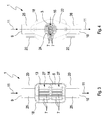
- Fig. 1 - 4th comprises an exhaust gas cooler 1, which is preferably an exhaust gas recirculation cooler, an exhaust gas inlet 2 and an exhaust gas outlet 3.
- the exhaust gas inlet 2 communicates with an inlet chamber 4, while the exhaust gas outlet 3 communicates with an outlet chamber 5.
- An exhaust gas flow 6 leading to the exhaust gas cooler 1 and leading away from the exhaust gas cooler 1 is indicated by arrows.
- the exhaust gas cooler 1 may preferably be used in an exhaust gas recirculation system of an internal combustion engine in order to cool recirculated exhaust gases.
- the internal combustion engine is preferably arranged in a motor vehicle.
- the exhaust gas cooler 1 has a plurality of exhaust pipes 7. These are according to the Fig. 3 - 17 designed as flat tubes. This means that the exhaust pipes 7 are significantly wider in cross section than high. For example, they are at least five times or at least ten times wider than high.
- the exhaust pipes 7 are expediently designed as identical parts.
- the exhaust pipes 7 extend parallel to each other and thereby extend through a coolant chamber 8 of the exhaust gas cooler 1.
- the exhaust pipes 7 are connected on the one hand communicating with the inlet chamber 4 and on the other hand with the outlet chamber 5.
- the exhaust gas cooler 1 has a coolant inlet 9, which is connected to the coolant chamber 8, and a coolant outlet 10, which is also communicatively connected to the coolant chamber 8.
- a coolant flow 11 is in Fig. 1 symbolically indicated by arrows.
- the exhaust gas cooler 1 is integrated into the exhaust gas flow 6 and into the coolant flow 11 in such a way that a flow is formed in countercurrent.
- the exhaust pipes 7 pass through a wall 12 on the inlet side and a wall 13 on the outlet side.
- the exhaust pipes 7 are attached to these walls 12, 13 in a gas-tight manner.
- the inlet side wall 12 separates the coolant chamber 8 from the inlet chamber 4.
- the outlet side wall 13 separates the coolant chamber 8 from the outlet chamber 5.
- the coolant chamber 8 is enclosed by a housing 14.
- a cross section 15 of the housing 14 is larger than a in Fig. 4 It is also larger than a cross section of the exhaust gas inlet 2, not shown here.
- the cross section of the exhaust gas inlet 2 is the same size as the cross section 16 of the exhaust gas outlet 3.
- the inlet chamber 4 is corresponding to the Fig.
- an inlet funnel 17 connects the exhaust gas inlet 2 to the housing 14, the outlet funnel 18 creates a connection between the housing 14 and the exhaust gas outlet 3.
- At least one of the funnels 17, 18 is fitted onto the housing 14 from outside.
- both funnels 17, 18 are plugged onto the housing 14 from the outside.
- an axial overlap region 19 is created, which in Fig. 2 indicated by a curly bracket. In this overlap region 19 and the respective wall 12 and 13 is arranged. Visible pushes the respective wall 12, 13 at the edge on an unspecified inside of the housing 14 and is connected to shock with the housing 14.
- the exhaust gas cooler 1 here has an inlet flange 21 and an outlet flange 22, with the aid of which the exhaust gas cooler 1 can be integrated into an exhaust gas recirculation line.
- the inlet flange 21 of the exhaust inlet 2 is arranged.
- an inlet pipe 23 is provided, which has the exhaust gas inlet 2 and on the one hand projects into the inlet flange 21 and on the other hand protrudes into the inlet funnel 17.
- an outlet pipe 24 is provided which, on the one hand, projects into the outlet funnel 18 and, on the other hand, projects into the outlet flange 22.
- this outlet pipe 24 has the exhaust gas outlet 3.
- the coolant inlet 9 is formed on an inlet port 25, which is suitably connected to the housing 14.
- an outlet port 26 is provided which has the coolant outlet 10 and which is suitably connected to the housing 14.
- the exhaust gas cooler 1 is made entirely of stainless steel. However, at least one of the following components is made of stainless steel: inlet flange 21, inlet tube 23, inlet funnel 17, inlet side wall 12, housing 14, outlet side wall 13, outlet funnel 18, outlet tube 24, outlet flange 22, exhaust tube 7, inlet nozzle 25, outlet nozzle 26, Fastening tab 20.
- the separately produced components of the exhaust gas cooler 1 are preferably fastened to one another via welded connections.
- Corresponding Fig. 3 can be arranged in the coolant chamber 8 at least two juxtaposed stack 27, each comprising a plurality of stacked exhaust pipes 7.
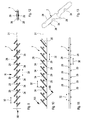
- Such bulges 29 are in the embodiments of Fig. 5-13 present, while in the embodiment of the Fig. 14 - 17 are not available. About these bulges 29 are supported adjacent exhaust pipes 7 in the embodiments of Fig. 5-13 directly to each other.
- bulges 29 in the embodiments presented here are the Fig. 5-13 arranged and configured so that at the superposed exhaust pipes 7, the bulges 29 of the one exhaust pipe 7 - apart from the respective first bulge 29 and the last bulge 29 - between two adjacent bulges 29 of the other exhaust pipe 7 directly to this other exhaust pipe. 7 issue.
- all bulges 29 of the one exhaust pipe 7 are in each case in the longitudinal direction 30 spaced from the nearest bulge 29 of the other exhaust pipe 7 directly to this other exhaust pipe 7 at.
- the distance between adjacent exhaust pipes 7 corresponds to the height of the bulges 29.
- the individual bulges 29 are arranged on the respective side 28 of the associated exhaust pipe 7 along a straight line 31 which extends parallel to the longitudinal direction 30 of the associated exhaust pipe 7.
- the bulges 29 may be arranged offset within the respective exhaust pipe 7 on the opposite sides 28 in the longitudinal direction 30 to each other.
- the offset carried out in the longitudinal direction 30 is expediently dimensioned such that it corresponds to half of a distance 32 measured in the longitudinal direction 30 between two adjacent bulges 29.
- the bulges 29 of one side are arranged with respect to a projection oriented perpendicular to the plane of the respective exhaust pipe 7 between, in particular centrally, two adjacent bulges 29 of the other side 28 of this exhaust pipe 7.
- each of the bulges 29 have a rectilinear shape.
- a longitudinal direction 33 of these rectilinear bulges 29 is aligned with respect to the longitudinal direction 30 of the associated exhaust pipe 7 inclined.
- the longitudinal direction 33 of the respective rectilinear bulge 29 is inclined by approximately 45 ° with respect to the longitudinal direction 30.
- the angle included between said longitudinal directions 33 and 30 is in a range of from 40 ° to 50 ° inclusive.
- all rectilinear bulges 29 are oriented parallel to each other on the respective side 28 of the associated exhaust pipe 7.
- the straight lobes 29 are inclined in the same direction and in particular parallel to each other with respect to the longitudinal direction 30 of the associated exhaust pipe 7 at the respective exhaust pipe 7 on the two opposite sides 28, in particular in a perpendicular to the plane of the respective exhaust pipe 7 projection.
- the Fig. 9 - 13 show another embodiment or a different shape for the bulges 29.
- they are designed in a projection which is oriented perpendicular to the plane of the respective exhaust pipe 7, circular.
- the bulges 29 are thus designed wart-shaped.
- they are each arranged centrally on the respective side 28 with respect to the broad direction of the respective exhaust pipe 7.
- the exhaust pipes 7 on the opposite sides 28 also more, inwardly projecting recesses 34. These are also spaced apart in the longitudinal direction 30 of the associated exhaust pipe 7. It is useful in the embodiments of the Fig. 5-13 shown arrangement in which 30 recesses 34 and bulges 29 alternate in the longitudinal direction. In each case a bulge 29 is arranged between two adjacent recesses 34.
- the recesses 34 are each formed in a straight line. They have a longitudinal direction 35, which also extends inclined relative to the longitudinal direction 30 of the associated exhaust pipe 7. It is expedient that all recesses 34 of the respective exhaust pipe 7 extend parallel to each other.
- the angle which the longitudinal direction 35 of the recesses 34 encloses with the longitudinal direction 30 of the associated exhaust pipe 7 is between 40 ° and 50 ° inclusive. In the example shown, said angle is 45 °.
- the longitudinal direction 33 of the bulges 29 extend parallel to the longitudinal direction 35 of the depressions 34.
- the depressions 34 on the two opposite sides 28 of the same exhaust gas pipe 7 are in the same direction with respect to the longitudinal direction 30 of the exhaust pipe 7 are inclined, resulting in the projection perpendicular to the plane of the respective exhaust pipe 7, a parallel arrangement of the rectilinear recesses 34 and the rectilinear bulges 29 results.
- the Fig. 5-13 are the recesses 34 in the longitudinal direction 30 of the associated exhaust pipe 7 narrower or shorter than the bulges 29. Further, the recesses 34 are transverse to the longitudinal direction 30 of the associated exhaust pipe 7 is greater or longer than the bulges 29. Accordingly Fig. 8
- the recesses 34 may expediently project into the interior of the respective exhaust pipe 7 so far that the recesses 34 on the opposite sides 28 abut one another in the interior of the exhaust pipe 7.
- the recesses 34 each protrude with a depth or height the exhaust pipe 7 in, which corresponds to half the distance of the opposite sides 28 of the exhaust pipe 7.
- the Fig. 5-13 are the recesses 34 and the bulges 29 coordinated so that the bulges 29 of the one exhaust pipe 7 in the region of the recesses 34 of the other exhaust pipe 7 abut the respective adjacent or other exhaust pipe 7, in such a way that thereby a coolant path is formed transversely to the longitudinal direction 30 of the exhaust pipes 7 can be flowed through.
- the respective coolant path is communicatively connected at its ends to the coolant chamber 8, since the bulges 29 can not completely cover the opposite depression 34. Between its ends, the respective coolant path is then delimited on the one hand by the respective depression 34 or by its wall and on the other hand by the respective bulge 29 or by its wall. With the help of these coolant paths, a targeted flow through the depressions 34 and flow around the bulges 29 is achieved. In this way, more surface may contact the coolant, which improves the heat transfer between the exhaust pipes 7 and the coolant.
- the exhaust pipes 7 each have a plurality of inwardly projecting recesses 36 on the opposite sides 28. In this embodiment, however, no bulges 29 are present.
- spacers can be provided, in addition, then either an edge, where no wave is, or the shaft can be interrupted.
- adjacent exhaust pipes 7 on the sides 28, which contain the recesses 36 lie directly and flat against each other and preferably be flat. For example, a distance of more than 1 mm can be maintained.
- the recesses 36 are configured or arranged so that they on the adjoining sides 28 and form at least one coolant path between adjacent exhaust pipes 7, which can be flowed through transversely to the longitudinal direction 30 of the exhaust pipes 7. Also, this coolant path communicates with the coolant chamber. 8
- the recesses 36 are in contrast to the embodiments of Fig. 5-13 not in the longitudinal direction 30 of the exhaust pipes 7, but transversely to the longitudinal direction 30 of the exhaust pipes 7 spaced from each other or arranged adjacent to each other. As in the FIGS. 14 and 15 is clearly visible, the recesses 36 are each configured continuously, so that they extend from an inlet-side longitudinal end portion 37 of the respective exhaust pipe 7 to an outlet side longitudinal end portion 38 of the respective exhaust pipe 7. This allows a cross-exchange of coolant over the entire length of the exhaust pipes 7 done.
- the depressions 36 are designed with a wavy or serpentine shape with respect to their longitudinal direction. Also conceivable are other shapes, such as a sawtooth shape.
- the arrangement or shaping of the recesses 36 takes place in such a way that the depressions 36 of the abutting sides 38 of adjacent exhaust pipes 7 intersect several times along the longitudinal direction 30 of the exhaust pipes 7.
- coolant can pass from the depressions 36 of one exhaust pipe 7 into the recesses 36 of the other, adjacent exhaust pipe 7.
- This improves the mixing and thus the heat transfer.
- the depressions 36 are formed or arranged within the respective exhaust pipe 7 in such a way that the depressions 36 of the opposite sides 28 in the interior of the respective exhaust pipe 7 along their longitudinal direction or along the longitudinal direction 30 of the exhaust pipe. 7 cut several times.
- a projection which is oriented perpendicular to the plane of the respective exhaust pipe 7.
- Corresponding Fig. 17 protrude the wells 36 in a preferred embodiment on the opposite sides 28 of the respective exhaust pipe 7 far into the interior of the respective exhaust pipe 7 in that they touch in the interior of the exhaust pipe 7.
- a symmetrical arrangement is expedient, so that the depressions 36 of the respective side 28 each overcome approximately half the distance between the sides 28.
- the recesses 36 are preferably flat against each other.
- the indentations can protrude into the exhaust pipe about 1/6 of the clear height. This leaves a continuous space in the middle.
Landscapes
- Engineering & Computer Science (AREA)
- Physics & Mathematics (AREA)
- Thermal Sciences (AREA)
- Mechanical Engineering (AREA)
- General Engineering & Computer Science (AREA)
- Geometry (AREA)
- Exhaust-Gas Circulating Devices (AREA)
- Heat-Exchange Devices With Radiators And Conduit Assemblies (AREA)
- Exhaust Gas After Treatment (AREA)
- Exhaust Silencers (AREA)
Applications Claiming Priority (1)
| Application Number | Priority Date | Filing Date | Title |
|---|---|---|---|
| DE102008064090A DE102008064090A1 (de) | 2008-12-19 | 2008-12-19 | Abgaskühler |
Publications (3)
| Publication Number | Publication Date |
|---|---|
| EP2199722A2 true EP2199722A2 (fr) | 2010-06-23 |
| EP2199722A3 EP2199722A3 (fr) | 2010-08-25 |
| EP2199722B1 EP2199722B1 (fr) | 2012-08-01 |
Family
ID=42061035
Family Applications (1)
| Application Number | Title | Priority Date | Filing Date |
|---|---|---|---|
| EP09177831A Not-in-force EP2199722B1 (fr) | 2008-12-19 | 2009-12-03 | Refroidisseur pour gaz d'échappement |
Country Status (4)
| Country | Link |
|---|---|
| US (1) | US8627880B2 (fr) |
| EP (1) | EP2199722B1 (fr) |
| JP (1) | JP5579428B2 (fr) |
| DE (1) | DE102008064090A1 (fr) |
Cited By (3)
| Publication number | Priority date | Publication date | Assignee | Title |
|---|---|---|---|---|
| WO2012079701A1 (fr) * | 2010-12-14 | 2012-06-21 | Daimler Ag | Échangeur thermique pour gaz d'échappement d'une machine à combustion interne |
| US8627880B2 (en) | 2008-12-19 | 2014-01-14 | Mahle International Gmbh | Exhaust gas cooler |
| WO2014048688A1 (fr) * | 2012-09-25 | 2014-04-03 | Behr Gmbh & Co. Kg | Tube plat |
Families Citing this family (11)
| Publication number | Priority date | Publication date | Assignee | Title |
|---|---|---|---|---|
| DE102008051268A1 (de) * | 2008-10-10 | 2010-04-15 | Mahle International Gmbh | Kühleinrichtung |
| JP2012112579A (ja) * | 2010-11-24 | 2012-06-14 | Mitsubishi Alum Co Ltd | 熱交換器用扁平チューブ及び熱交換器 |
| JP5768795B2 (ja) * | 2011-10-18 | 2015-08-26 | カルソニックカンセイ株式会社 | 排気熱交換装置 |
| JP5764535B2 (ja) * | 2012-07-13 | 2015-08-19 | 株式会社ユタカ技研 | 熱交換器 |
| JP5921413B2 (ja) * | 2012-10-30 | 2016-05-24 | カルソニックカンセイ株式会社 | 熱交換器用チューブ |
| US20160123683A1 (en) * | 2014-10-30 | 2016-05-05 | Ford Global Technologies, Llc | Inlet air turbulent grid mixer and dimpled surface resonant charge air cooler core |
| US10598382B2 (en) | 2014-11-07 | 2020-03-24 | United Technologies Corporation | Impingement film-cooled floatwall with backside feature |
| EP3270085B1 (fr) * | 2016-07-12 | 2019-11-06 | Borgwarner Emissions Systems Spain, S.L.U. | Échangeur thermique pour système egr |
| CN110017496B (zh) * | 2017-05-11 | 2020-05-12 | 中国北方车辆研究所 | 分散换热结构格栅孔变化的余热利用换热装置 |
| US11098962B2 (en) * | 2019-02-22 | 2021-08-24 | Forum Us, Inc. | Finless heat exchanger apparatus and methods |
| DE102024118441A1 (de) * | 2024-06-28 | 2025-12-31 | Ms Motorservice International Gmbh | Abgasrückführungskühler |
Citations (4)
| Publication number | Priority date | Publication date | Assignee | Title |
|---|---|---|---|---|
| US6453989B1 (en) | 1999-05-31 | 2002-09-24 | Mitsubishi Heavy Industries, Ltd. | Heat exchanger |
| US6453988B1 (en) | 1999-07-28 | 2002-09-24 | Mitsubishi Heavy Industries, Ltd. | Heat exchanger and dimple tube used in the same, the tube having larger opposed protrusions closest to each end of tube |
| US6892806B2 (en) | 2000-06-17 | 2005-05-17 | Behr Gmbh & Co. | Heat exchanger for motor vehicles |
| US6920918B2 (en) | 2002-03-30 | 2005-07-26 | Modine Manufacturing Company | Heat exchanger |
Family Cites Families (15)
| Publication number | Priority date | Publication date | Assignee | Title |
|---|---|---|---|---|
| US2017201A (en) * | 1931-11-27 | 1935-10-15 | Modine Mfg Co | Condenser tube |
| KR940010978B1 (ko) * | 1988-08-12 | 1994-11-21 | 갈소니꾸 가부시끼가이샤 | 멀티플로우형의 열교환기 |
| US4932469A (en) * | 1989-10-04 | 1990-06-12 | Blackstone Corporation | Automotive condenser |
| US5186250A (en) * | 1990-05-11 | 1993-02-16 | Showa Aluminum Kabushiki Kaisha | Tube for heat exchangers and a method for manufacturing the tube |
| US6371201B1 (en) * | 1996-04-03 | 2002-04-16 | Ford Global Technologies, Inc. | Heat exchanger and method of assembly for automotive vehicles |
| DE19654368B4 (de) * | 1996-12-24 | 2006-01-05 | Behr Gmbh & Co. Kg | Wärmeübertrager, insbesondere Abgaswärmeübertrager |
| JP3299148B2 (ja) * | 1997-09-16 | 2002-07-08 | 株式会社ゼクセルヴァレオクライメートコントロール | 熱交換器用チューブとその製造方法 |
| EP1256772A3 (fr) * | 2001-05-11 | 2005-02-09 | Behr GmbH & Co. KG | Echangeur de chaleur |
| US6516874B2 (en) * | 2001-06-29 | 2003-02-11 | Delaware Capital Formation, Inc. | All welded plate heat exchanger |
| DE10249724B4 (de) * | 2002-10-25 | 2005-03-17 | Bayer Industry Services Gmbh & Co. Ohg | Hochleistungs-Temperierkanäle |
| DE10302708A1 (de) * | 2003-01-23 | 2004-07-29 | Behr Gmbh & Co. Kg | Vorrichtung zum Austausch von Wärme |
| US20110056652A1 (en) | 2006-01-23 | 2011-03-10 | Behr Gmbh & Co. Kg | Heat exchanger |
| ITVR20060154A1 (it) * | 2006-10-06 | 2008-04-07 | Gianfranco Natali | Procedimento per la realizzazione di tubi di scambiatori di calore e tubi di scambiatori di calore |
| DE102007061059A1 (de) * | 2007-12-14 | 2009-06-18 | Smk Systeme Metall Kunststoff Gmbh & Co. | Abgaskühler |
| DE102008064090A1 (de) | 2008-12-19 | 2010-08-12 | Mahle International Gmbh | Abgaskühler |
-
2008
- 2008-12-19 DE DE102008064090A patent/DE102008064090A1/de not_active Withdrawn
-
2009
- 2009-12-03 EP EP09177831A patent/EP2199722B1/fr not_active Not-in-force
- 2009-12-15 JP JP2009283690A patent/JP5579428B2/ja not_active Expired - Fee Related
- 2009-12-18 US US12/642,068 patent/US8627880B2/en not_active Expired - Fee Related
Patent Citations (4)
| Publication number | Priority date | Publication date | Assignee | Title |
|---|---|---|---|---|
| US6453989B1 (en) | 1999-05-31 | 2002-09-24 | Mitsubishi Heavy Industries, Ltd. | Heat exchanger |
| US6453988B1 (en) | 1999-07-28 | 2002-09-24 | Mitsubishi Heavy Industries, Ltd. | Heat exchanger and dimple tube used in the same, the tube having larger opposed protrusions closest to each end of tube |
| US6892806B2 (en) | 2000-06-17 | 2005-05-17 | Behr Gmbh & Co. | Heat exchanger for motor vehicles |
| US6920918B2 (en) | 2002-03-30 | 2005-07-26 | Modine Manufacturing Company | Heat exchanger |
Cited By (4)
| Publication number | Priority date | Publication date | Assignee | Title |
|---|---|---|---|---|
| US8627880B2 (en) | 2008-12-19 | 2014-01-14 | Mahle International Gmbh | Exhaust gas cooler |
| WO2012079701A1 (fr) * | 2010-12-14 | 2012-06-21 | Daimler Ag | Échangeur thermique pour gaz d'échappement d'une machine à combustion interne |
| WO2014048688A1 (fr) * | 2012-09-25 | 2014-04-03 | Behr Gmbh & Co. Kg | Tube plat |
| US10520261B2 (en) | 2012-09-25 | 2019-12-31 | Mahle International Gmbh | Flat pipe |
Also Published As
| Publication number | Publication date |
|---|---|
| EP2199722B1 (fr) | 2012-08-01 |
| US20100162699A1 (en) | 2010-07-01 |
| JP2010144723A (ja) | 2010-07-01 |
| JP5579428B2 (ja) | 2014-08-27 |
| DE102008064090A1 (de) | 2010-08-12 |
| US8627880B2 (en) | 2014-01-14 |
| EP2199722A3 (fr) | 2010-08-25 |
Similar Documents
| Publication | Publication Date | Title |
|---|---|---|
| EP2199722B1 (fr) | Refroidisseur pour gaz d'échappement | |
| DE69306065T2 (de) | Wärmetauscher | |
| EP0514326B1 (fr) | Catalyseur pour le traitement catalytique de gaz d'échappement | |
| EP1830042B1 (fr) | Mélangeur statique et dispositif de traitement de gaz d'échappement | |
| EP1994349B1 (fr) | Unité de transfert thermique | |
| DE202010018520U1 (de) | Wärmetauscher | |
| EP2169338B1 (fr) | Refroidisseur de gaz | |
| EP1604163A1 (fr) | Echangeur thermique, notamment refroidisseur de gaz d'echappement pour automobiles | |
| DE2951352C2 (de) | Flachrohr-Wärmetauscher | |
| EP1906130A2 (fr) | Echangeur thermique destiné au refroidissement des gaz, procédé destiné à la fabrication d'un échangeur thermique | |
| EP1504230A2 (fr) | Echangeur thermique, notamment refroidisseur d'air de suralimentation | |
| DE19515526C1 (de) | Flachrohrwärmetauscher mit mindestens zwei Fluten für Kraftfahrzeuge | |
| WO2018154063A1 (fr) | Échangeur thermique et réacteur | |
| EP2485007A2 (fr) | Echangeur de chaleur avec tubes à ailettes | |
| DE102012208354B4 (de) | Wärmetauscher | |
| EP1929233B1 (fr) | Refroidisseur d'air de suralimentation ou refroidisseur de gaz d'echappement pour un moteur a combustion interne d'un vehicule automobile | |
| DE2952736A1 (de) | Waermetauscher, insbesondere zwei-oder mehrflutiger kondensator fuer klimaanlagen in kraftfahrzeugen | |
| DE102011077154B4 (de) | Verdampfer | |
| EP3039372B1 (fr) | Échangeur de chaleur | |
| WO2013153095A1 (fr) | Générateur thermoélectrique comprenant un échangeur de chaleur | |
| WO2016131786A1 (fr) | Échangeur de chaleur à faisceau tubulaire | |
| EP1788320B1 (fr) | Echangeur de chaleur | |
| WO2017167872A1 (fr) | Échangeur de chaleur à plaques empilées | |
| EP3066407B1 (fr) | Échangeur de chaleur | |
| DE19654363A1 (de) | Wärmeübertrager, insbesondere Abgaswärmeübertrager |
Legal Events
| Date | Code | Title | Description |
|---|---|---|---|
| PUAI | Public reference made under article 153(3) epc to a published international application that has entered the european phase |
Free format text: ORIGINAL CODE: 0009012 |
|
| AK | Designated contracting states |
Kind code of ref document: A2 Designated state(s): AT BE BG CH CY CZ DE DK EE ES FI FR GB GR HR HU IE IS IT LI LT LU LV MC MK MT NL NO PL PT RO SE SI SK SM TR |
|
| AX | Request for extension of the european patent |
Extension state: AL BA RS |
|
| PUAL | Search report despatched |
Free format text: ORIGINAL CODE: 0009013 |
|
| AK | Designated contracting states |
Kind code of ref document: A3 Designated state(s): AT BE BG CH CY CZ DE DK EE ES FI FR GB GR HR HU IE IS IT LI LT LU LV MC MK MT NL NO PL PT RO SE SI SK SM TR |
|
| AX | Request for extension of the european patent |
Extension state: AL BA RS |
|
| 17P | Request for examination filed |
Effective date: 20110218 |
|
| 17Q | First examination report despatched |
Effective date: 20110629 |
|
| GRAP | Despatch of communication of intention to grant a patent |
Free format text: ORIGINAL CODE: EPIDOSNIGR1 |
|
| GRAS | Grant fee paid |
Free format text: ORIGINAL CODE: EPIDOSNIGR3 |
|
| GRAA | (expected) grant |
Free format text: ORIGINAL CODE: 0009210 |
|
| AK | Designated contracting states |
Kind code of ref document: B1 Designated state(s): AT BE BG CH CY CZ DE DK EE ES FI FR GB GR HR HU IE IS IT LI LT LU LV MC MK MT NL NO PL PT RO SE SI SK SM TR |
|
| REG | Reference to a national code |
Ref country code: GB Ref legal event code: FG4D Free format text: NOT ENGLISH |
|
| REG | Reference to a national code |
Ref country code: AT Ref legal event code: REF Ref document number: 568899 Country of ref document: AT Kind code of ref document: T Effective date: 20120815 Ref country code: CH Ref legal event code: EP |
|
| REG | Reference to a national code |
Ref country code: IE Ref legal event code: FG4D Free format text: LANGUAGE OF EP DOCUMENT: GERMAN |
|
| REG | Reference to a national code |
Ref country code: DE Ref legal event code: R096 Ref document number: 502009004236 Country of ref document: DE Effective date: 20120927 |
|
| REG | Reference to a national code |
Ref country code: NL Ref legal event code: VDEP Effective date: 20120801 |
|
| REG | Reference to a national code |
Ref country code: LT Ref legal event code: MG4D Effective date: 20120801 |
|
| PG25 | Lapsed in a contracting state [announced via postgrant information from national office to epo] |
Ref country code: NO Free format text: LAPSE BECAUSE OF FAILURE TO SUBMIT A TRANSLATION OF THE DESCRIPTION OR TO PAY THE FEE WITHIN THE PRESCRIBED TIME-LIMIT Effective date: 20121101 Ref country code: HR Free format text: LAPSE BECAUSE OF FAILURE TO SUBMIT A TRANSLATION OF THE DESCRIPTION OR TO PAY THE FEE WITHIN THE PRESCRIBED TIME-LIMIT Effective date: 20120801 Ref country code: IS Free format text: LAPSE BECAUSE OF FAILURE TO SUBMIT A TRANSLATION OF THE DESCRIPTION OR TO PAY THE FEE WITHIN THE PRESCRIBED TIME-LIMIT Effective date: 20121201 Ref country code: CY Free format text: LAPSE BECAUSE OF FAILURE TO SUBMIT A TRANSLATION OF THE DESCRIPTION OR TO PAY THE FEE WITHIN THE PRESCRIBED TIME-LIMIT Effective date: 20120801 Ref country code: FI Free format text: LAPSE BECAUSE OF FAILURE TO SUBMIT A TRANSLATION OF THE DESCRIPTION OR TO PAY THE FEE WITHIN THE PRESCRIBED TIME-LIMIT Effective date: 20120801 Ref country code: LT Free format text: LAPSE BECAUSE OF FAILURE TO SUBMIT A TRANSLATION OF THE DESCRIPTION OR TO PAY THE FEE WITHIN THE PRESCRIBED TIME-LIMIT Effective date: 20120801 |
|
| PG25 | Lapsed in a contracting state [announced via postgrant information from national office to epo] |
Ref country code: GR Free format text: LAPSE BECAUSE OF FAILURE TO SUBMIT A TRANSLATION OF THE DESCRIPTION OR TO PAY THE FEE WITHIN THE PRESCRIBED TIME-LIMIT Effective date: 20121102 Ref country code: SI Free format text: LAPSE BECAUSE OF FAILURE TO SUBMIT A TRANSLATION OF THE DESCRIPTION OR TO PAY THE FEE WITHIN THE PRESCRIBED TIME-LIMIT Effective date: 20120801 Ref country code: PL Free format text: LAPSE BECAUSE OF FAILURE TO SUBMIT A TRANSLATION OF THE DESCRIPTION OR TO PAY THE FEE WITHIN THE PRESCRIBED TIME-LIMIT Effective date: 20120801 Ref country code: SE Free format text: LAPSE BECAUSE OF FAILURE TO SUBMIT A TRANSLATION OF THE DESCRIPTION OR TO PAY THE FEE WITHIN THE PRESCRIBED TIME-LIMIT Effective date: 20120801 Ref country code: PT Free format text: LAPSE BECAUSE OF FAILURE TO SUBMIT A TRANSLATION OF THE DESCRIPTION OR TO PAY THE FEE WITHIN THE PRESCRIBED TIME-LIMIT Effective date: 20121203 Ref country code: LV Free format text: LAPSE BECAUSE OF FAILURE TO SUBMIT A TRANSLATION OF THE DESCRIPTION OR TO PAY THE FEE WITHIN THE PRESCRIBED TIME-LIMIT Effective date: 20120801 |
|
| PG25 | Lapsed in a contracting state [announced via postgrant information from national office to epo] |
Ref country code: NL Free format text: LAPSE BECAUSE OF FAILURE TO SUBMIT A TRANSLATION OF THE DESCRIPTION OR TO PAY THE FEE WITHIN THE PRESCRIBED TIME-LIMIT Effective date: 20120801 |
|
| PG25 | Lapsed in a contracting state [announced via postgrant information from national office to epo] |
Ref country code: ES Free format text: LAPSE BECAUSE OF FAILURE TO SUBMIT A TRANSLATION OF THE DESCRIPTION OR TO PAY THE FEE WITHIN THE PRESCRIBED TIME-LIMIT Effective date: 20121112 Ref country code: DK Free format text: LAPSE BECAUSE OF FAILURE TO SUBMIT A TRANSLATION OF THE DESCRIPTION OR TO PAY THE FEE WITHIN THE PRESCRIBED TIME-LIMIT Effective date: 20120801 Ref country code: EE Free format text: LAPSE BECAUSE OF FAILURE TO SUBMIT A TRANSLATION OF THE DESCRIPTION OR TO PAY THE FEE WITHIN THE PRESCRIBED TIME-LIMIT Effective date: 20120801 Ref country code: CZ Free format text: LAPSE BECAUSE OF FAILURE TO SUBMIT A TRANSLATION OF THE DESCRIPTION OR TO PAY THE FEE WITHIN THE PRESCRIBED TIME-LIMIT Effective date: 20120801 Ref country code: RO Free format text: LAPSE BECAUSE OF FAILURE TO SUBMIT A TRANSLATION OF THE DESCRIPTION OR TO PAY THE FEE WITHIN THE PRESCRIBED TIME-LIMIT Effective date: 20120801 |
|
| PG25 | Lapsed in a contracting state [announced via postgrant information from national office to epo] |
Ref country code: SK Free format text: LAPSE BECAUSE OF FAILURE TO SUBMIT A TRANSLATION OF THE DESCRIPTION OR TO PAY THE FEE WITHIN THE PRESCRIBED TIME-LIMIT Effective date: 20120801 Ref country code: IT Free format text: LAPSE BECAUSE OF FAILURE TO SUBMIT A TRANSLATION OF THE DESCRIPTION OR TO PAY THE FEE WITHIN THE PRESCRIBED TIME-LIMIT Effective date: 20120801 |
|
| PLBE | No opposition filed within time limit |
Free format text: ORIGINAL CODE: 0009261 |
|
| STAA | Information on the status of an ep patent application or granted ep patent |
Free format text: STATUS: NO OPPOSITION FILED WITHIN TIME LIMIT |
|
| BERE | Be: lapsed |
Owner name: MAHLE INTERNATIONAL G.M.B.H. Effective date: 20121231 |
|
| 26N | No opposition filed |
Effective date: 20130503 |
|
| PG25 | Lapsed in a contracting state [announced via postgrant information from national office to epo] |
Ref country code: MC Free format text: LAPSE BECAUSE OF NON-PAYMENT OF DUE FEES Effective date: 20121231 Ref country code: BG Free format text: LAPSE BECAUSE OF FAILURE TO SUBMIT A TRANSLATION OF THE DESCRIPTION OR TO PAY THE FEE WITHIN THE PRESCRIBED TIME-LIMIT Effective date: 20121101 |
|
| REG | Reference to a national code |
Ref country code: DE Ref legal event code: R097 Ref document number: 502009004236 Country of ref document: DE Effective date: 20130503 |
|
| REG | Reference to a national code |
Ref country code: IE Ref legal event code: MM4A |
|
| PG25 | Lapsed in a contracting state [announced via postgrant information from national office to epo] |
Ref country code: BE Free format text: LAPSE BECAUSE OF NON-PAYMENT OF DUE FEES Effective date: 20121231 |
|
| PG25 | Lapsed in a contracting state [announced via postgrant information from national office to epo] |
Ref country code: IE Free format text: LAPSE BECAUSE OF NON-PAYMENT OF DUE FEES Effective date: 20121203 |
|
| PG25 | Lapsed in a contracting state [announced via postgrant information from national office to epo] |
Ref country code: MT Free format text: LAPSE BECAUSE OF FAILURE TO SUBMIT A TRANSLATION OF THE DESCRIPTION OR TO PAY THE FEE WITHIN THE PRESCRIBED TIME-LIMIT Effective date: 20120801 |
|
| PG25 | Lapsed in a contracting state [announced via postgrant information from national office to epo] |
Ref country code: TR Free format text: LAPSE BECAUSE OF FAILURE TO SUBMIT A TRANSLATION OF THE DESCRIPTION OR TO PAY THE FEE WITHIN THE PRESCRIBED TIME-LIMIT Effective date: 20120801 |
|
| PG25 | Lapsed in a contracting state [announced via postgrant information from national office to epo] |
Ref country code: SM Free format text: LAPSE BECAUSE OF FAILURE TO SUBMIT A TRANSLATION OF THE DESCRIPTION OR TO PAY THE FEE WITHIN THE PRESCRIBED TIME-LIMIT Effective date: 20120801 Ref country code: LU Free format text: LAPSE BECAUSE OF NON-PAYMENT OF DUE FEES Effective date: 20121203 |
|
| PG25 | Lapsed in a contracting state [announced via postgrant information from national office to epo] |
Ref country code: HU Free format text: LAPSE BECAUSE OF FAILURE TO SUBMIT A TRANSLATION OF THE DESCRIPTION OR TO PAY THE FEE WITHIN THE PRESCRIBED TIME-LIMIT Effective date: 20091203 |
|
| REG | Reference to a national code |
Ref country code: CH Ref legal event code: PL |
|
| PG25 | Lapsed in a contracting state [announced via postgrant information from national office to epo] |
Ref country code: CH Free format text: LAPSE BECAUSE OF NON-PAYMENT OF DUE FEES Effective date: 20131231 Ref country code: LI Free format text: LAPSE BECAUSE OF NON-PAYMENT OF DUE FEES Effective date: 20131231 |
|
| PG25 | Lapsed in a contracting state [announced via postgrant information from national office to epo] |
Ref country code: MK Free format text: LAPSE BECAUSE OF FAILURE TO SUBMIT A TRANSLATION OF THE DESCRIPTION OR TO PAY THE FEE WITHIN THE PRESCRIBED TIME-LIMIT Effective date: 20120801 |
|
| REG | Reference to a national code |
Ref country code: FR Ref legal event code: PLFP Year of fee payment: 7 |
|
| REG | Reference to a national code |
Ref country code: AT Ref legal event code: MM01 Ref document number: 568899 Country of ref document: AT Kind code of ref document: T Effective date: 20141203 |
|
| PG25 | Lapsed in a contracting state [announced via postgrant information from national office to epo] |
Ref country code: AT Free format text: LAPSE BECAUSE OF NON-PAYMENT OF DUE FEES Effective date: 20141203 |
|
| REG | Reference to a national code |
Ref country code: FR Ref legal event code: PLFP Year of fee payment: 8 |
|
| REG | Reference to a national code |
Ref country code: FR Ref legal event code: PLFP Year of fee payment: 9 |
|
| PGFP | Annual fee paid to national office [announced via postgrant information from national office to epo] |
Ref country code: GB Payment date: 20181029 Year of fee payment: 18 |
|
| PGFP | Annual fee paid to national office [announced via postgrant information from national office to epo] |
Ref country code: DE Payment date: 20190228 Year of fee payment: 10 |
|
| REG | Reference to a national code |
Ref country code: DE Ref legal event code: R119 Ref document number: 502009004236 Country of ref document: DE |
|
| GBPC | Gb: european patent ceased through non-payment of renewal fee |
Effective date: 20191203 |
|
| PG25 | Lapsed in a contracting state [announced via postgrant information from national office to epo] |
Ref country code: GB Free format text: LAPSE BECAUSE OF NON-PAYMENT OF DUE FEES Effective date: 20191203 Ref country code: DE Free format text: LAPSE BECAUSE OF NON-PAYMENT OF DUE FEES Effective date: 20200701 |
|
| PGFP | Annual fee paid to national office [announced via postgrant information from national office to epo] |
Ref country code: FR Payment date: 20201229 Year of fee payment: 12 |
|
| PG25 | Lapsed in a contracting state [announced via postgrant information from national office to epo] |
Ref country code: FR Free format text: LAPSE BECAUSE OF NON-PAYMENT OF DUE FEES Effective date: 20211231 |