EP2199574A1 - Brennkraftmaschine mit einer Drosselklappenanlage - Google Patents
Brennkraftmaschine mit einer Drosselklappenanlage Download PDFInfo
- Publication number
- EP2199574A1 EP2199574A1 EP09008589A EP09008589A EP2199574A1 EP 2199574 A1 EP2199574 A1 EP 2199574A1 EP 09008589 A EP09008589 A EP 09008589A EP 09008589 A EP09008589 A EP 09008589A EP 2199574 A1 EP2199574 A1 EP 2199574A1
- Authority
- EP
- European Patent Office
- Prior art keywords
- throttle
- combustion engine
- internal combustion
- throttle body
- engine according
- Prior art date
- Legal status (The legal status is an assumption and is not a legal conclusion. Google has not performed a legal analysis and makes no representation as to the accuracy of the status listed.)
- Granted
Links
Images


Classifications
-
- F—MECHANICAL ENGINEERING; LIGHTING; HEATING; WEAPONS; BLASTING
- F02—COMBUSTION ENGINES; HOT-GAS OR COMBUSTION-PRODUCT ENGINE PLANTS
- F02D—CONTROLLING COMBUSTION ENGINES
- F02D9/00—Controlling engines by throttling air or fuel-and-air induction conduits or exhaust conduits
- F02D9/08—Throttle valves specially adapted therefor; Arrangements of such valves in conduits
- F02D9/10—Throttle valves specially adapted therefor; Arrangements of such valves in conduits having pivotally-mounted flaps
- F02D9/109—Throttle valves specially adapted therefor; Arrangements of such valves in conduits having pivotally-mounted flaps having two or more flaps
- F02D9/1095—Rotating on a common axis, e.g. having a common shaft
-
- F—MECHANICAL ENGINEERING; LIGHTING; HEATING; WEAPONS; BLASTING
- F02—COMBUSTION ENGINES; HOT-GAS OR COMBUSTION-PRODUCT ENGINE PLANTS
- F02D—CONTROLLING COMBUSTION ENGINES
- F02D9/00—Controlling engines by throttling air or fuel-and-air induction conduits or exhaust conduits
- F02D9/08—Throttle valves specially adapted therefor; Arrangements of such valves in conduits
- F02D9/10—Throttle valves specially adapted therefor; Arrangements of such valves in conduits having pivotally-mounted flaps
- F02D9/1035—Details of the valve housing
Definitions
- the invention relates to an internal combustion engine with a throttle valve system according to the preamble of claim 1.
- a throttle valve system in which a single throttle body are provided in a throttle body.
- a single throttle valve is arranged for each intake port, which is connected to a drive shaft, which is rotatably mounted in a throttle body.
- a reference portion is provided, on which the respective air duct is held biased by means of a clamping device.
- the object of the invention is to provide an internal combustion engine with a throttle valve system, in which a tightness of the throttle valve, in particular in the control of small loads and idle, is ensured.
- the advantages achieved by the invention are that by floating inner air duct for each throttle in a common outer throttle body optimum tightness of the throttle can be achieved. This is achieved according to the invention by the individual throttle valves are pivotally mounted on the continuous shaft respectively disposed in the inner air duct, which are held floating between bearings of the common outer throttle body on the shaft.
- the individual air ducts are aligned with a thermal expansion of the cylinder head of the adjustable throttle in the longitudinal direction of the continuous shaft, regardless of a movement of the connected to the throttle body Saugrohrflansches the cylinder head.
- this embodiment of the invention is achieved in an advantageous manner that can align in the thermal expansion of the cylinder head and the outer throttle body, the individual air duct by the individual throttle valves such that a relative movement of the air duct in the longitudinal direction of the drive shaft can be done and thus the individual Throttles in the associated and floating air duct are sealingly positioned.
- the throttle valves in an approximately tapered bore of the air duct u. a. are arranged obliquely in a sealing position and each air duct in response to a throttle position to achieve a tightness of the throttle in the air guide pipe is slidably held in the outer throttle body.
- the bearings for the air duct in the throttle body each consist of parallel opposed inner sliding surfaces, which are arranged corresponding to parallel outer support surfaces of the air duct.
- a wall surface adjoining the support surfaces and surrounding the throttle flap is in each case arranged at a distance from an outer wall of the common throttle valve housing.
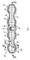
- An internal combustion engine is provided with a throttle valve system 1, which is arranged between a cylinder head 2 and intake pipes. Adjoining the intake pipes is an outer common throttle body 3, in which inner air guide nozzles 4, which are provided with throttle valves 5, are held in a floating manner in bearings 6 of the throttle body 3.
- the throttle valves 5 are all arranged on a common continuous shaft 7 and pivotable about this, which is in Fig. 1 and 2 is shown in more detail.
- the shaft 7 is connected to an adjusting element 8, which is provided centrally between the four throttle valves 5 in the common throttle body 3.
- the adjusting element 8 is positioned laterally from the center or at one end of the shaft 7.
- each throttle valve 5 is fixedly connected to each other via the continuous shaft 7 and thus only pivotable together, wherein each throttle valve 5 includes an associated air guide 4, which is floatingly mounted in the common throttle body 3.
- each throttle valve 5 includes an associated air guide 4, which is floatingly mounted in the common throttle body 3.
- the individual air guide stub 4 after the individual throttle 5, so that only the common throttle body 3 moves with the Saugrohrflansch 12 of the cylinder head 2.
- the common throttle body 3 also still provides for a necessary sealing of the throttle valve system 1 to the outside, so that no so-called. False air can be sucked.
- the openings or holes 10 of the air guide pipe 4 are made slightly tapered, so that when tilting the throttle valve 5 in a sealing position optimum tightness can be achieved. It is still conceivable, the openings or holes 10 form oval or elliptical.
- the floating bearing 6 for the individual air duct 4 in the throttle body 3 consists of parallel opposing inner sliding surfaces V, V1, which correspond to corresponding outer support surfaces A, A1 of the air duct 4.
- a wall surface W adjoining the supporting surface A, A1 and surrounding the throttle flap 5 is arranged at a distance from an outer wall W1 of the throttle body 3, so that heat transfer is avoided.
- Each air duct 4 is pressed by means of a spring element 11, which is preferably designed in the form of an elastic 0-ring, to the Saugrohrflansch 12 and brought to Saugrohrflansch 12 to the plant.
- a spring element 11 is arranged in a groove 13 formed on the throttle body 3.
- On the side of the Saugrohrflansches 12 prevents the spring element 11 by pressing the air duct 4 to the Saugrohrflansch 12 the Vorbefiströmen of false air between the respective air duct 4 and the Saugrohrflansch 12, wherein the spring element 11 on the other side of the air duct 4 in addition Sealing device between the respective air duct 4 and the throttle body 3 is used.
Landscapes
- Engineering & Computer Science (AREA)
- Chemical & Material Sciences (AREA)
- Combustion & Propulsion (AREA)
- Mechanical Engineering (AREA)
- General Engineering & Computer Science (AREA)
- Control Of Throttle Valves Provided In The Intake System Or In The Exhaust System (AREA)
Abstract
Description
- Die Erfindung bezieht sich auf eine Brennkraftmaschine mit einer Drosselklappenanlage nach dem Oberbegriff des Anspruchs 1.
- Aus der
DE 10 2007 000 752 A1 ist eine Drosselklappenanlage bekannt, bei der in einem Drosselklappengehäuse einzelne Luftführungsstutzen vorgesehen sind. An den jeweiligen Luftführungsstutzen ist für jeden Ansaugkanal eine Einzeldrosselklappe angeordnet, die mit einer Antriebswelle verbunden wird, wobei diese drehbar in einem Drosselklappengehäuse gelagert ist. Weiterhin ist ein Bezugsabschnitt vorgesehen, an dem der jeweilige Luftführungsstutzen mit Hilfe einer Spanneinrichtung vorgespannt gehalten wird. Hierdurch ist eine relative Position des jeweiligen Luftführungsstutzens im Hinblick auf die jeweilige Antriebswelle definierbar. - Die Aufgabe der Erfindung besteht darin, eine Brennkraftmaschine mit einer Drosselklappenanlage zu schaffen, bei der eine Dichtheit der Drosselklappe, insbesondere bei der Regelung von kleinen Lasten und im Leerlauf, gewährleistet ist.
- Diese Aufgabe wird erfindungsgemäß durch die Merkmale des Anspruchs 1 gelöst. Weitere vorteilhafte Merkmale beinhalten die Unteransprüche.
- Die mit der Erfindung hauptsächlich erzielten Vorteile bestehen darin, dass durch schwimmend gelagerte innere Luftführungsstutzen für die einzelnen Drosselklappen in einem gemeinsamen äußeren Drosselklappengehäuse eine optimale Dichtheit der Drosselklappen erzielt werden kann. Dies wird nach der Erfindung erreicht, indem die einzelnen Drosselklappen schwenkbar verbunden auf der durchgehenden Welle jeweils in den inneren Luftführungsstutzen angeordnet sind, welche schwimmend zwischen Lagerungen des gemeinsamen äußeren Drosselklappengehäuses auf der Welle gehalten werden.
- Des Weiteren ist nach der Erfindung vorgesehen, dass die einzelnen Luftführungsstutzen bei einer Wärmeausdehnung des Zylinderkopfes von den verstellbaren Drosselklappen in Längsrichtung der durchgehenden Welle, unabhängig von einer Bewegung des mit dem Drosselklappengehäuse verbundenen Saugrohrflansches des Zylinderkopfes, ausrichtbar sind. Durch diese Ausführung der Erfindung wird in vorteilhafter Weise erreicht, dass sich bei der Wärmeausdehnung des Zylinderkopfes bzw. des äußeren Drosselklappengehäuses die einzelnen Luftführungsstutzen nach den einzelnen Drosselklappen derart ausrichten können, dass eine relative Bewegung der Luftführungsstutzen in Längsrichtung der Antriebswelle erfolgen kann und somit die einzelnen Drosselklappen im zugehörigen und schwimmend gelagerten Luftführungsstutzen dichtend positionierbar sind.
- Ferner ist nach der Erfindung vorgesehen, dass die Drosselklappen in einer etwa konisch zulaufenden Bohrung des Luftführungsstutzens u. a. in einer Dichtstellung schräg stehend angeordnet sind und jeder Luftführungsstutzen in Abhängigkeit von einer Drosselklappenstellung zur Erzielung einer Dichtheit der Drosselklappe im Luftführungsstutzen verschiebbar im äußeren Drosselklappengehäuse gehalten ist. Hierdurch kann eine Ausrichtung der Luftführungsstutzen über die Drosselklappen in einfacher Weise erfolgen.
- Nach einer weiteren Ausführung der Erfindung ist vorgesehen, dass die Lagerungen für die Luftführungsstutzen im Drosselklappengehäuse jeweils aus parallel gegenüberstehenden inneren Verschiebeflächen bestehen, die korrespondierend zu parallelen äußeren Abstützflächen des Luftführungsstutzens angeordnet sind.
- Ferner ist nach der Erfindung vorgesehen, dass eine an die Abstützflächen anschließende und die Drosselklappe umgebende Wandungsfläche jeweils beabstandet zu einer Außenwand des gemeinsamen Drosselklappengehäuses angeordnet ist. Durch diese Ausbildung der Lagerungen der einzelnen Luftführungsstutzen kann sich dieser in Achsrichtung der Welle ungehindert verschieben und es wird ein Wärmeübergang vermieden.
- Ein Ausführungsbeispiel der Erfindung ist in den Zeichnungen dargestellt und wird im Folgenden näher beschrieben. Es zeigen:
- Fig. 1
- eine Draufsicht auf ein äußeres Drosselklappengehäuse mit schwimmend gelagerten inneren Luftführungsstutzen und Drosselklappen auf einer gemeinsamen Welle,
- Fig. 2
- einen Schnitt nach der Linie II-II der
Fig. 1 durch das Drosselklappengehäuse, - Fig. 3
- einen Schnitt nach der Linie III-III der
Fig. 1 durch das Drosselklappengehäuse mit Luftführungsstutzen und - Fig. 4
- eine Schnittdarstellung durch einen Teil des Zylinderkopfes mit einem angeflanschten Drosselklappengehäuse und innen liegenden Luftführungsstutzen für die Drosselklappen.
- Eine Brennkraftmaschine ist mit einer Drosselklappenanlage 1 versehen, die zwischen einem Zylinderkopf 2 und Ansaugleitungen angeordnet ist. An die Ansaugleitungen schließt sich ein äußeres gemeinsames Drosselklappengehäuse 3 an, in dem mit Drosselklappen 5 versehende innere Luftführungsstutzen 4 schwimmend in Lagerungen 6 des Drosselklappengehäuses 3 gehalten sind. Die Drosselklappen 5 sind alle auf einer gemeinsamen durchgehenden Welle 7 angeordnet und über diese verschwenkbar, was in
Fig. 1 und2 näher dargestellt ist. Hierzu ist die Welle 7 mit einem Verstellelement 8 verbunden, das mittig zwischen den vier Drosselklappen 5 im gemeinsamen Drosselklappengehäuse 3 vorgesehen ist. Alternativ ist das Verstellelement 8 seitlich von der Mitte oder an einem Ende der Welle 7 positioniert. - Die einzelnen Drosselklappen 5 sind über die durchgehende Welle 7 fest miteinander verbunden und somit nur gemeinsam schwenkbar, wobei jede Drosselklappe 5 einen zugehörigen Luftführungsstutzen 4 umfasst, der in dem gemeinsamen Drosselklappengehäuse 3 schwimmend gelagert ist. Bei einer Wärmeausdehnung des Zylinderkopfes 2 der Brennkraftmaschine richten sich die einzelnen Luftführungsstutzen 4 nach den einzelnen Drosselklappen 5 aus, sodass sich nur das gemeinsame Drosselklappengehäuse 3 mit dem Saugrohrflansch 12 des Zylinderkopfes 2 bewegt. Somit kann durch die schwimmende Lagerung jedes einzelnen Luftführungsstutzens 4 ein Spalt zwischen der Drosselklappe 5 und dem zugehörigen Luftführungsstutzen 4 minimiert werden. Das gemeinsame Drosselklappengehäuse 3 sorgt zudem noch für eine notwendige Abdichtung der Drosselklappenanlage 1 nach außen hin, damit keine sog. Falschluft angesaugt werden kann.
- Wie in
Fig. 2 gezeigt, sind die Öffnungen bzw. Bohrungen 10 der Luftführungsstutzen 4 leicht konisch zulaufend ausgeführt, so dass bei Schrägstellung der Drosselklappen 5 in einer Dichtstellung eine optimale Dichtheit erzielbar ist. Es ist dennoch denkbar, die Öffnungen bzw. Bohrungen 10 ovalförmig oder elliptisch auszubilden. - Die schwimmende Lagerung 6 für die einzelnen Luftführungsstutzen 4 im Drosselklappengehäuse 3 besteht jeweils aus parallel gegenüberstehenden inneren Verschiebeflächen V, V1, denen hierzu korrespondierende äußere Abstützflächen A, A1 des Luftführungsstutzens 4 gegenüberstehen. Ein an die Abstützfläche A, A1 anschließende und die Drosselklappe 5 umgebende Wandungsfläche W ist beabstandet zu einer Außenwand W1 des Drosselklappengehäuses 3 angeordnet, sodass ein Wärmeübergang vermieden wird.
- Gemäß Fig. wird jeder Luftführungsstutzen 4 mit Hilfe eines Federelements 11, das vorzugsweise in Form eins elastischen 0-Rings ausgebildet ist, an den Saugrohrflansch 12 gedrückt bzw. am Saugrohrflansch 12 zur Anlage gebracht. Ein solches Federelement 11 ist in einer am Drosselklappengehäuse 3 ausgebildeten Nut 13 angeordnet. Auf der Seite des Saugrohrflansches 12 verhindert das Federelement 11 durch das Pressen des Luftführungsstutzens 4 an den Saugrohrflansch 12 das Vorbeiströmen von Falschluft zwischen dem jeweiligen Luftführungsstutzen 4 und dem Saugrohrflansch 12, wobei das Federelement 11 auf der anderen Seite des Luftführungsstutzens 4 zusätzlich als Dichteinrichtung zwischen dem jeweiligen Luftführungsstutzen 4 und dem Drosselklappengehäuse 3 dient.
Claims (9)
- Brennkraftmaschine mit einer Drosselklappenanlage, die zwischen einem Zylinderkopf und Ansaugleitungen angeordnet ist und mehrere in einem Drosselklappengehäuse angeordnete Drosselklappen umfasst, die gemeinsam über ein Verstellelement verschwenkbar auf einer durchgehenden Welle angeordnet sind, dadurch gekennzeichnet, dass die einzelnen Drosselklappen (5) schwenkbar verbunden auf der durchgehenden Welle (7) jeweils in einem inneren Luftführungsstutzen (4) angeordnet und diese Luftführungsstutzen (4) schwimmend zwischen Lagerungen (6) im äußeren gemeinsamen Drosselklappengehäuses (3) auf der Welle (7) gehalten sind.
- Brennkraftmaschine nach Anspruch 1, dadurch gekennzeichnet, dass die einzelnen Luftführungsstutzen (4) bei einer Wärmeausdehnung des Zylinderkopfes (2) von den verstellbaren Drosselklappen (5) in Längsrichtung der durchgehenden Welle (7), unabhängig von einer Bewegung des mit dem Drosselklappengehäuse (3) verbundenen Saugrohrflansches (12) des Zylinderkopfes, ausrichtbar sind.
- Brennkraftmaschine nach den Ansprüchen 1 oder 2, dadurch gekennzeichnet, dass die Drosselklappen (5) in einer etwa konisch zulaufenden Bohrung des Luftführungsstutzens (4) angeordnet und mit der Welle (7)fest verbunden sind
- Brennkraftmaschine nach einem der Ansprüche 1 bis 3, dadurch gekennzeichnet, dass jeder Luftführungsstutzen (4) in Abhängigkeit von einer Drosselklappenstellung zur Erzielung einer Dichtheit der Drosselklappe (5) im Luftführungsstutzen (4) verschiebbar im äußeren Drosselklappengehäuse (3) gehalten wird.
- Brennkraftmaschine nach einem der Ansprüche 1 bis 4, dadurch gekennzeichnet, dass die Lager (6) für die Luftführungsstutzen (4) im Drosselklappengehäuse (3) jeweils aus parallel gegenüberstehenden inneren Verschiebeflächen (V, V1) bestehen, die korrespondierend zu parallelen äußeren Abstützflächen (A, A1) des Luftführungsstutzens (4) angeordnet sind.
- Brennkraftmaschine nach einem der Ansprüche 1 bis 5, dadurch gekennzeichnet, dass eine an die Abstützflächen (A, A1) anschließende und die Drosselklappe (5) umgebende Wandungsfläche (W) beabstandet zu einer Außenwand (W1) des Drosselklappengehäuses (3) angeordnet ist.
- Brennkraftmaschine nach einem der Ansprüche 1 bis 6, dadurch gekennzeichnet, dass das gemeinsame Verstellelement (8) für die Drosselklappe (5) mittig zwischen den mindestens vier Luftführungsstutzen (4) im äußeren Drosselklappengehäuse (3) angeordnet ist.
- Brennkraftmaschine nach einem der Ansprüche 1 bis 7, dadurch gekennzeichnet, dass das Drosselklappengehäuse (3) über eine Ringdichtung (R) am Saugrohrflansch (12) des Zylinderkopfes (2) abgedichtet gehalten ist.
- Brennkraftmaschine nach einem der Ansprüche 1 bis 8, dadurch gekennzeichnet, dass zwischen dem Luftführungsstutzen (4) und dem Drosselklappengehäuse (3) ein Federelement (11) positioniert ist, das vorzugsweise in Form eins 0-Rings ausgebildet ist.
Applications Claiming Priority (1)
| Application Number | Priority Date | Filing Date | Title |
|---|---|---|---|
| DE102008064539A DE102008064539A1 (de) | 2008-12-19 | 2008-12-19 | Drosselklappenanlage für eine Brennkraftmaschine |
Publications (2)
| Publication Number | Publication Date |
|---|---|
| EP2199574A1 true EP2199574A1 (de) | 2010-06-23 |
| EP2199574B1 EP2199574B1 (de) | 2016-12-28 |
Family
ID=41697812
Family Applications (1)
| Application Number | Title | Priority Date | Filing Date |
|---|---|---|---|
| EP09008589.5A Ceased EP2199574B1 (de) | 2008-12-19 | 2009-07-01 | Brennkraftmaschine mit einer Drosselklappenanlage |
Country Status (2)
| Country | Link |
|---|---|
| EP (1) | EP2199574B1 (de) |
| DE (1) | DE102008064539A1 (de) |
Cited By (1)
| Publication number | Priority date | Publication date | Assignee | Title |
|---|---|---|---|---|
| WO2013064498A1 (de) * | 2011-11-03 | 2013-05-10 | Avl List Gmbh | Einlassstrang für eine brennkraftmaschine |
Citations (5)
| Publication number | Priority date | Publication date | Assignee | Title |
|---|---|---|---|---|
| US20070144483A1 (en) * | 2005-12-26 | 2007-06-28 | Denso Corporation | Valve assembly having a sealing member |
| DE102007000434A1 (de) | 2006-08-11 | 2008-02-14 | Denso Corp., Kariya | Integrierte Ventilvorrichtung |
| FR2905159A1 (fr) * | 2007-09-14 | 2008-02-29 | Mark Iv Systemes Moteurs Soc P | Dispositif de regulation a clapet et collecteur d'admission comprenant au moins un tel dispositif. |
| DE102007000752A1 (de) | 2006-09-21 | 2008-04-03 | Aisin Seiki K.K., Kariya | Lufteinlasssteuerungsgerät |
| US20080110430A1 (en) | 2006-11-10 | 2008-05-15 | Aisin Seiki Kabushiki Kaisha | Intake system of internal combustion engine |
Family Cites Families (3)
| Publication number | Priority date | Publication date | Assignee | Title |
|---|---|---|---|---|
| DE19503771A1 (de) * | 1995-02-04 | 1996-08-08 | Mann & Hummel Filter | Saugmodul |
| DE19800207A1 (de) * | 1997-03-20 | 1998-09-24 | Mann & Hummel Filter | Saugmodul |
| DE10032740A1 (de) * | 2000-07-05 | 2002-02-21 | Mann & Hummel Filter | Luftansaugvorrichtung für eine Brennkraftmaschine |
-
2008
- 2008-12-19 DE DE102008064539A patent/DE102008064539A1/de not_active Ceased
-
2009
- 2009-07-01 EP EP09008589.5A patent/EP2199574B1/de not_active Ceased
Patent Citations (5)
| Publication number | Priority date | Publication date | Assignee | Title |
|---|---|---|---|---|
| US20070144483A1 (en) * | 2005-12-26 | 2007-06-28 | Denso Corporation | Valve assembly having a sealing member |
| DE102007000434A1 (de) | 2006-08-11 | 2008-02-14 | Denso Corp., Kariya | Integrierte Ventilvorrichtung |
| DE102007000752A1 (de) | 2006-09-21 | 2008-04-03 | Aisin Seiki K.K., Kariya | Lufteinlasssteuerungsgerät |
| US20080110430A1 (en) | 2006-11-10 | 2008-05-15 | Aisin Seiki Kabushiki Kaisha | Intake system of internal combustion engine |
| FR2905159A1 (fr) * | 2007-09-14 | 2008-02-29 | Mark Iv Systemes Moteurs Soc P | Dispositif de regulation a clapet et collecteur d'admission comprenant au moins un tel dispositif. |
Cited By (1)
| Publication number | Priority date | Publication date | Assignee | Title |
|---|---|---|---|---|
| WO2013064498A1 (de) * | 2011-11-03 | 2013-05-10 | Avl List Gmbh | Einlassstrang für eine brennkraftmaschine |
Also Published As
| Publication number | Publication date |
|---|---|
| EP2199574B1 (de) | 2016-12-28 |
| DE102008064539A1 (de) | 2010-06-24 |
Similar Documents
| Publication | Publication Date | Title |
|---|---|---|
| DE602004012023T2 (de) | Rückschlagventil | |
| DE102016102252B4 (de) | Regel- oder Absperrarmatur | |
| EP2510266B1 (de) | Mehrwegeventil | |
| DE8711049U1 (de) | Ventil | |
| WO2006116957A1 (de) | Abgasrückführeinrichtung | |
| EP2199574B1 (de) | Brennkraftmaschine mit einer Drosselklappenanlage | |
| EP1712818B1 (de) | Membranventil | |
| DE102005005190A1 (de) | Abgaskühleranordnung für ein Kraftfahrzeug | |
| AT414155B (de) | Brennkraftmaschine mit 2-stufigem abgasturbolader und ladeluftkühlung zwischen nieder- und hochdruckverdichter | |
| EP3591268B1 (de) | Fluidleitungsverbinder mit fixiertem einsatzteil zur drosslung | |
| EP1952011B1 (de) | Kraftstoff-einspritzvorrichtung für eine brennkraftmaschine mit kraftstoff-direkteinspritzung | |
| EP1170483A2 (de) | Luftansaugvorrichtung für eine Brennkraftmaschine | |
| EP4476431B1 (de) | Regelvorrichtung eines abgasführungsabschnitts eines abgasturboladers | |
| DE102007056665A1 (de) | Stellzylinder | |
| DE102006017213A1 (de) | Metallische Flachdichtung mit zerbrechlichen Verbindungsabschnitten | |
| DE102009061109B3 (de) | Koaxialventil mit Dichtelement | |
| DE19543897C5 (de) | Stellantrieb für ein Stellglied eines Regel- oder Steuerventils | |
| EP3405655B1 (de) | Turbolader mit schieber zur flutenverbindung | |
| WO2003095815A1 (de) | Klappenventil für luftansaugkanal einer brennkraftmaschine | |
| DE10317053B4 (de) | Abgasrohr einer aufgeladenen Brennkraftmaschine | |
| DE10139302C1 (de) | Luftansaugkanalsystem für Brennkraftmaschinen | |
| DE102014216263B3 (de) | Dampfventilvorrichtung | |
| DE102014207671B4 (de) | Abgasturbolader mit einem Wastegate-Ventil | |
| DE4417669A1 (de) | Absperrarmatur zum Absperren einer Strömung | |
| DE102019105710A1 (de) | Axialventil |
Legal Events
| Date | Code | Title | Description |
|---|---|---|---|
| PUAI | Public reference made under article 153(3) epc to a published international application that has entered the european phase |
Free format text: ORIGINAL CODE: 0009012 |
|
| AK | Designated contracting states |
Kind code of ref document: A1 Designated state(s): DE FR GB IT |
|
| AX | Request for extension of the european patent |
Extension state: AL BA RS |
|
| 17P | Request for examination filed |
Effective date: 20101223 |
|
| 17Q | First examination report despatched |
Effective date: 20110207 |
|
| GRAP | Despatch of communication of intention to grant a patent |
Free format text: ORIGINAL CODE: EPIDOSNIGR1 |
|
| INTG | Intention to grant announced |
Effective date: 20160729 |
|
| GRAS | Grant fee paid |
Free format text: ORIGINAL CODE: EPIDOSNIGR3 |
|
| GRAA | (expected) grant |
Free format text: ORIGINAL CODE: 0009210 |
|
| AK | Designated contracting states |
Kind code of ref document: B1 Designated state(s): DE FR GB IT |
|
| REG | Reference to a national code |
Ref country code: GB Ref legal event code: FG4D Free format text: NOT ENGLISH |
|
| REG | Reference to a national code |
Ref country code: DE Ref legal event code: R096 Ref document number: 502009013509 Country of ref document: DE |
|
| REG | Reference to a national code |
Ref country code: FR Ref legal event code: PLFP Year of fee payment: 9 |
|
| REG | Reference to a national code |
Ref country code: DE Ref legal event code: R097 Ref document number: 502009013509 Country of ref document: DE |
|
| PLBE | No opposition filed within time limit |
Free format text: ORIGINAL CODE: 0009261 |
|
| STAA | Information on the status of an ep patent application or granted ep patent |
Free format text: STATUS: NO OPPOSITION FILED WITHIN TIME LIMIT |
|
| 26N | No opposition filed |
Effective date: 20170929 |
|
| REG | Reference to a national code |
Ref country code: FR Ref legal event code: PLFP Year of fee payment: 10 |
|
| PGFP | Annual fee paid to national office [announced via postgrant information from national office to epo] |
Ref country code: IT Payment date: 20190730 Year of fee payment: 11 Ref country code: FR Payment date: 20190719 Year of fee payment: 11 |
|
| PGFP | Annual fee paid to national office [announced via postgrant information from national office to epo] |
Ref country code: GB Payment date: 20190719 Year of fee payment: 11 |
|
| GBPC | Gb: european patent ceased through non-payment of renewal fee |
Effective date: 20200701 |
|
| PG25 | Lapsed in a contracting state [announced via postgrant information from national office to epo] |
Ref country code: GB Free format text: LAPSE BECAUSE OF NON-PAYMENT OF DUE FEES Effective date: 20200701 Ref country code: FR Free format text: LAPSE BECAUSE OF NON-PAYMENT OF DUE FEES Effective date: 20200731 |
|
| PG25 | Lapsed in a contracting state [announced via postgrant information from national office to epo] |
Ref country code: IT Free format text: LAPSE BECAUSE OF NON-PAYMENT OF DUE FEES Effective date: 20200701 |
|
| P01 | Opt-out of the competence of the unified patent court (upc) registered |
Effective date: 20230526 |
|
| PGFP | Annual fee paid to national office [announced via postgrant information from national office to epo] |
Ref country code: DE Payment date: 20230628 Year of fee payment: 15 |
|
| REG | Reference to a national code |
Ref country code: DE Ref legal event code: R119 Ref document number: 502009013509 Country of ref document: DE |
|
| PG25 | Lapsed in a contracting state [announced via postgrant information from national office to epo] |
Ref country code: DE Free format text: LAPSE BECAUSE OF NON-PAYMENT OF DUE FEES Effective date: 20250201 |