EP2199031A1 - Outil d'impact - Google Patents
Outil d'impact Download PDFInfo
- Publication number
- EP2199031A1 EP2199031A1 EP08830366A EP08830366A EP2199031A1 EP 2199031 A1 EP2199031 A1 EP 2199031A1 EP 08830366 A EP08830366 A EP 08830366A EP 08830366 A EP08830366 A EP 08830366A EP 2199031 A1 EP2199031 A1 EP 2199031A1
- Authority
- EP
- European Patent Office
- Prior art keywords
- weight part
- reaction force
- actuating member
- weights
- hammer actuating
- Prior art date
- Legal status (The legal status is an assumption and is not a legal conclusion. Google has not performed a legal analysis and makes no representation as to the accuracy of the status listed.)
- Granted
Links
Images


Classifications
-
- B—PERFORMING OPERATIONS; TRANSPORTING
- B25—HAND TOOLS; PORTABLE POWER-DRIVEN TOOLS; MANIPULATORS
- B25D—PERCUSSIVE TOOLS
- B25D17/00—Details of, or accessories for, portable power-driven percussive tools
- B25D17/24—Damping the reaction force
-
- B—PERFORMING OPERATIONS; TRANSPORTING
- B25—HAND TOOLS; PORTABLE POWER-DRIVEN TOOLS; MANIPULATORS
- B25D—PERCUSSIVE TOOLS
- B25D17/00—Details of, or accessories for, portable power-driven percussive tools
- B25D17/06—Hammer pistons; Anvils ; Guide-sleeves for pistons
-
- B—PERFORMING OPERATIONS; TRANSPORTING
- B25—HAND TOOLS; PORTABLE POWER-DRIVEN TOOLS; MANIPULATORS
- B25D—PERCUSSIVE TOOLS
- B25D2211/00—Details of portable percussive tools with electromotor or other motor drive
- B25D2211/003—Crossed drill and motor spindles
-
- B—PERFORMING OPERATIONS; TRANSPORTING
- B25—HAND TOOLS; PORTABLE POWER-DRIVEN TOOLS; MANIPULATORS
- B25D—PERCUSSIVE TOOLS
- B25D2222/00—Materials of the tool or the workpiece
- B25D2222/21—Metals
- B25D2222/42—Steel
-
- B—PERFORMING OPERATIONS; TRANSPORTING
- B25—HAND TOOLS; PORTABLE POWER-DRIVEN TOOLS; MANIPULATORS
- B25D—PERCUSSIVE TOOLS
- B25D2250/00—General details of portable percussive tools; Components used in portable percussive tools
- B25D2250/371—Use of springs
Definitions
- the invention relates to an impact tool for performing a linear hammering operation on a workpiece, and more particularly to a technique for cushioning a reaction force received from the workpiece during hammering operation.
- Japanese non-examined laid-open Patent Publication No. 2007-50495 discloses a technique for cushioning an impact force (reaction force) caused by rebound of a tool bit after its striking movement in an impact tool.
- This impact tool has an impact absorbing mechanism which includes a weight that is placed in contact with the impact bolt during hammering operation and a coil spring that biases the weight in a direction that holds the weight in contact with the impact bolt.
- the impact absorbing mechanism is designed such that, when a rearward reaction force acts upon the impact bolt by rebound of the tool bit after striking movement of the tool bit, the weight is caused to move rearward by the reaction force transmitted from the impact bolt and the coil spring elastically deforms rearward by the movement of the weight.
- an object of the invention to provide an impact tool which is improved in its structure for absorbing an impact force caused by rebound of a tool bit after its striking movement.
- Representative impact tool includes a tool body, a hammer actuating member that is disposed in a tip end region of the tool body and performs a predetermined hammering operation on a workpiece by linear movement in its axial direction, and a striking element that linearly moves in the axial direction of the hammer actuating member and thereby strikes the hammer actuating member.
- the "predetermined hammering operation” in this invention includes not only a hammering operation in which the hammer actuating member performs only a linear striking movement, but a hammer drill operation in which it performs a linear striking movement and a rotation in the circumferential direction.
- the "hammer actuating member” in this invention typically represents a tool bit and an impact bolt that transmits a striking force in the state of contact with the tool bit.
- the impact tool according to the invention further includes a weight part and an elastically deformable elastic element.
- a reaction force is transmitted from the hammer actuating member to the weight part in a reaction force transmitting position in which the weight part is placed in direct contact with the hammer actuating member or in which the weight part is placed in contact with the hammer actuating member via a hard metal intervening member.
- the weight part moves from the reaction force transmitting position in a direction different from the axial direction of the hammer actuating member by the transmitted reaction force.
- the weight part changes in its state between a first state in which the reaction force is not yet transmitted to the weight part and a second state in which the weight part is caused to move by the transmission of the reaction force in the direction different from the axial direction of the hammer actuating member.
- the elastic element exerts a biasing force such that the weight part is placed in the first state, and when the weight part changes from the first state to the second state by the reaction force, the elastic element elastically deforms by being pushed by the weight part and thereby absorbs the reaction force transmitted to the weight part.
- the "different direction” in this invention includes not only a radial direction of the hammer actuating member or an obliquely rearward direction including a radial component, but all directions other than the axial direction of the hammer actuating member.
- the “elastic element” in this invention typically comprises a spring, but it may comprise a rubber.
- the hammer actuating member is caused to rebound by receiving the reaction force from the workpiece after its striking movement.
- the reaction force received by the hammer actuating member from the workpiece is transmitted to the weight part in a reaction force transmitting position in which the weight part is placed in direct contact with the hammer actuating member or in which the weight part is placed in contact with the hammer actuating member via a hard metal intervening member, the reaction force is almost 100% transmitted.
- the reaction force is transmitted by exchange of momentum between the hammer actuating member and the weight part.
- the weight part is caused to move in a direction different from the axial direction of the hammer actuating member.
- the weight moving in this direction elastically deforms the elastic element, and the reaction force of the weight is absorbed by such elastic deformation.
- the reaction force caused by rebound of the hammer actuating member can be absorbed by the movement of the weight part in a direction different from the axial direction of the hammer actuating member and by the elastic deformation of the elastic element which is caused by the movement of the weight part. As a result, vibration of the impact power tool can be reduced.
- the impact absorbing mechanism formed by the weight part and the elastic element can be reduced in size in the axial direction of the hammer actuating member.
- the weight part comprises at least two weights disposed side by side along a circumferential direction on the hammer actuating member, and when the reaction force is transmitted from the hammer actuating member to the weights, the weights are moved by the reaction force in a direction transverse to the axial direction of the hammer actuating member.
- the "transverse direction” typically represents a radially outward direction of the hammer actuating member, but it is only necessary to include a component of the radially outward direction. Therefore, the "elastic element” in this invention preferably comprises a generally C-shaped plate spring that is disposed on the outside of the at least two weights and biases the weights radially inward at the same time.
- the elastic element may however be designed to bias the weights individually.
- the movement of the weights in a direction transverse to the axial direction of the hammer actuating member can be effected by direct contact of the weight with the hammer actuating member, or by contact of the weight with the hammer actuating member via an intervening member, via their tapered surfaces.
- the weights disposed on the outside of the hammer actuating member can be moved by utilizing a space on the outside (the radially outer side) of the hammer actuating member. Therefore, the impact absorbing mechanism can be further reduced in size in the axial direction of the hammer actuating member.
- the weight part comprises a large number of bead-like weights disposed in circumferential and axial directions of the hammer actuating member.
- the large number of the weights can be biased by the hammer actuating member such that adjacent ones of the weights are held in contact with each other while some of the weights are held in contact with the hammer actuating member.
- the reaction force is transmitted from the hammer actuating member to the some weights, the reaction force is successively transmitted starting from the some weights to the adjacent weights.
- the weights are moved as a whole in a direction that elastically deforms the elastic member while each moving in random directions.
- the "bead-like weights” in this invention typically represent steel balls, but their shape is not limited to a spherical shape and widely includes polyhedral, fusiform and other shapes.
- the direction of deformation of the "elastic element” in this invention is typically the axial direction of the hammer actuating member.
- the reaction force transmitted from the hammer actuating member can be dispersed over the weights, and loss of the reaction force is increased by transmission of the reaction force between the adjacent weights. Therefore, the effect of damping the reaction force is increased, so that the reaction force upon the elastic element can be reduced. As a result, durability of the elastic element can be increased.
- an impact tool which is improved in its structure for absorbing an impact force caused by rebound of a tool bit after its striking movement.
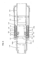
- FIG. 1 is a sectional side view showing an entire electric hammer drill 101 as a representative example of an impact tool according to the invention, under loaded conditions in which a hammer bit is pressed against a workpiece.
- the hammer drill 101 of this embodiment includes a body 103 that forms an outer shell of the hammer drill 101, a hammer bit 119 detachably coupled to the tip end region (on the left side as viewed in FIG. 1 ) of the body 103 via a tool holder 137, and a handgrip 109 that is connected to the body 103 on the side opposite the hammer bit 119 and designed to be held by a user.
- the body 103 is a feature that corresponds to the "tool body” according to the invention.
- the hammer bit 119 is held by the tool holder 137 such that it is allowed to reciprocate with respect to the tool holder 137 in its axial direction and prevented from rotating with respect to the tool holder 137 in its circumferential direction.
- the side of the hammer bit 119 is taken as the front and the side of the handgrip 109 as the rear.
- the body 103 includes a motor housing 105 that houses a driving motor 111, and a gear housing 107 that houses a motion converting mechanism 113, a striking mechanism 115 and a power transmitting mechanism 117 which form a driving mechanism.
- the rotating output of the driving motor 111 is appropriately converted to linear motion by the motion converting mechanism 113 and then transmitted to the striking mechanism 115.
- an impact force is generated in the axial direction of the hammer bit 119 via the striking mechanism 115.
- the speed of the rotating output of the driving motor 111 is appropriately reduced by the power transmitting mechanism 117 and then transmitted to the hammer bit 119.
- the hammer bit 119 is caused to rotate in the circumferential direction.
- the handgrip 109 is generally U-shaped in side view, having a lower end and an upper end.
- the lower end of the handgrip 109 is rotatably connected to the rear end lower portion of the motor housing 105 via a pivot 109a, and the upper end is connected to the rear end upper portion of the motor housing 105 via an elastic spring 109b for absorbing vibration.
- an elastic spring 109b for absorbing vibration.
- the motion converting mechanism 113 mainly includes a crank mechanism.
- the crank mechanism is designed such that, when the crank mechanism is rotationally driven by the driving motor 111, a driving element in the form of a piston 129 forming a final movable member of the crank mechanism linearly moves in the axial direction of the hammer bit.
- the power transmitting mechanism 117 mainly includes a gear speed reducing mechanism formed by a plurality of gears and serves to transmit rotation of the driving motor 111 to the tool holder 137.
- the tool holder 137 is caused to rotate in the vertical plane, and the hammer bit 119 held by the tool holder 137 rotates.
- the striking mechanism 115 mainly includes a striker 143 that is slidably disposed within the bore of the cylinder 141.
- the striker 143 is a feature that corresponds to the "striking element" according to this invention.
- the striker 143 is driven via the action of an air spring of an air chamber 141a of the cylinder 141 which is caused by sliding movement of the piston 129.
- the striker 143 then collides with (strikes) an intermediate element in the form of an impact bolt 145 that is slidably disposed within the tool holder 137 and transmits the striking force to the hammer bit 119 via the impact bolt 145.
- the impact bolt 145 and the hammer bit 119 are features that correspond to the "hammer actuating member" according to this invention.
- the impact bolt 145 includes a large-diameter portion 145a which is formed in the front in the longitudinal direction and fitted in close contact with the inner surface of the tool holder 137, a first small-diameter portion 145b provided for defining a predetermined extent of a space between the small-diameter portion 145b and the inner circumferential surface of the tool holder 137, and a second small-diameter portion 145c on which a positioning member 151 which is described below is loosely fitted and which is struck by the striker 143.
- a medium-diameter portion 145d having a larger diameter than the first small-diameter portion 145b and the second small-diameter portion 145c is formed between the small-diameter portions and has a tapered surface on its front and rear surfaces. Further, a tapered surface 145e is formed between the large-diameter portion 145a and the first small-diameter portion 145b. A contact surface of the large-diameter portion 145a which is placed in contact with a rear end surface of the hammer bit 119 is spherically convex.
- the hammer drill 101 includes a positioning member 151 that is disposed between the impact bolt 145 and the cylinder 141 and serves to position the body 103 with respect to the workpiece under loaded conditions shown in FIG. 1 in which the hammer bit 119 is pressed against the workpiece by the user's pressing force applied forward to the body 103.
- the positioning member 151 positions the body 103 with respect to the workpiece by contact with the impact bolt 145 and the cylinder 141, between the impact bolt 145 and the cylinder 141 which is held prevented at least from rearward movement with respect to the gear housing 107, when the positioning member 151 is pushed rearward (to the piston 129 side) together with the hammer bit 119.
- the positioning member 151 is a unit part including a rubber ring 153, a front hard metal washer 155 joined to the axially front surface of the rubber ring 153, and a rear hard metal washer 157 joined to the axially rear surface of the rubber ring 153.
- the positioning member 151 is loosely fitted onto the second small-diameter portion 145c of the impact bolt 145.
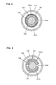
- the hammer drill 101 In order to absorb the impact force (reaction force) that is caused by rebound of the hammer bit 119 after the striking movement of the hammer bit 119 during hammering operation on the workpiece, the hammer drill 101 according to this embodiment includes a weight part 163 that contacts the impact bolt 145 and a plate spring 165 that exerts a biasing force in such a manner as to cause the weight part 163 to contact the impact bolt 145 and thereby allow transmission of the reaction force from the impact bolt 145.
- the weight part 163 and the plate spring 165 are features that correspond to the "weight part” and the "elastic element", respectively, according to this invention.
- the weight part 163 and the plate spring 165 form an impact absorbing mechanism 161, and the impact absorbing mechanism 161 is disposed on the first small-diameter portion 145b of the impact bolt 145.
- the weight part 163 is formed by two hard metal weights 163a, 163b shaped like two halves of a cylindrical body.
- the two weights 163a, 163b are disposed side by side in the circumferential direction on the first small-diameter portion 145b of the impact bolt 145 in such a manner as to surround the first small-diameter portion 145b and thereby forms the generally cylindrical weight part 163.
- the plate spring 165 is shaped like a generally C-shaped ring having a slit in the longitudinal direction and fitted on the two weights 163a, 163b under a predetermined initial load so as to bias the two weights 163a, 163b radially inward.
- the two weights 163a, 163b forming the weight part 163 can move radially outward under a biasing force of the plate spring 165.
- This radially outward direction corresponds to the "direction different from the axial direction" according to this invention.
- the plate spring 165 is fitted in a circumferential groove formed in the outer circumferential surface of each of the weights 163a, 163b and thereby prevented from moving in the longitudinal direction with respect to the weights 163a, 163b. Therefore, the relative positions of the two weights 163a, 163b in the longitudinal direction are held constant with respect to each other.
- both end surfaces of each of the weights 163a,163b in the longitudinal direction are tapered.
- the front tapered end surface of each weight is held in contact with the tapered surface 145e of the impact bolt 145, and the rear tapered end surface is held in surface contact with the front tapered surface of the medium-diameter portion 145d of the impact bolt 145 via the rubber ring 164.
- the two weights 163a, 163b are placed in an initial state in which a reaction force can be transmitted, with their end surfaces in the longitudinal direction held in contact with the impact bolt 145 under the radially inward biasing force of the plate spring 165.
- This initial state corresponds to the "first state" in this invention.
- the position at which the front end surfaces of the weights 163a, 163b contact the tapered surface 145e of the impact bolt 145 corresponds to the "reaction force transmitting position" in this invention.
- the rubber ring 164 is provided as a viscoelastic member that absorbs transmission of a stress wave from the weight part 163 to the impact bolt 145 during transmission of a reaction force from the impact bolt 145 to the weight part 163, while absorbing transmission of a stress wave from the impact bolt 145 to the weight part 163 during striking movement.
- the rotating output of the driving motor 111 is transmitted to the tool holder 137 via the gear speed reducing mechanism forming the power transmitting mechanism 117.
- the tool holder 137 and the hammer bit 119 held by the tool holder 137 rotate together.
- the hammer bit 119 performs a striking movement in its axial direction and a rotary movement in its circumferential direction, so that a hammer drill operation is performed on a workpiece.
- the hammer bit 119 After striking movement of the hammer bit 119 upon the workpiece, the hammer bit 119 is caused to rebound by receiving the reaction force from the workpiece. This rebound causes the impact bolt 145 to be acted upon by a rearward reaction force. At this time, the weights 163a, 163b of the weight part 163 are in contact with the tapered surface 145e of the impact bolt 145. Therefore, the reaction force of the impact bolt 145 is transmitted to the weight part 163. In other words, momentum is exchanged between the impact bolt 145 and the weight part 163.
- the impact bolt 145 is held substantially at rest in the reaction force transmitting position, while the weights 163a, 163b of the weight part 163 are moved radially outward from the initial position shown in FIGS. 2 and 3 .
- the weights 163a, 163b are held in contact with the impact bolt 145 via their tapered surfaces inclined with respect the longitudinal direction of the impact bolt 145, so that the weights 163a, 163b are moved radially outward by radial components of the reaction force transmitted to the weights 163a, 163b.
- the state in which the weights 163a, 163b are moved radially outward corresponds to the "second state" in this invention.
- the radially outward movement of the weights 163a, 163b causes the plate spring 165 to elastically deform in such a manner as to expand radially outward. This state is shown in FIG. 4 .
- the weight part 163 is designed to move radially by utilizing the property of the stress wave that spherically propagates. Specifically, when a rearward reaction force is applied to the front end of the impact bolt 145 by rebound of the hammer bit 119, a stress wave originating in the point of contact (axial center) of the impact bolt 145 with the hammer bit 119 spherically propagates rearward through the impact bolt, and then the stress wave is transmitted to the weights 163a, 163b which are held in contact with the tapered surface 145e inclined with respect the longitudinal direction of the impact bolt 145 via their tapered surfaces. By such transmission of the stress wave via the tapered surfaces, the stress wave smoothly propagates and the weights 163a, 163b are efficiently moved radially outward by the radial components of the transmitted stress wave.
- the reaction force caused by rebound of the hammer bit 119 and the impact bolt 145 can be efficiently absorbed by the radially outward movement of the weight part 163 and by the elastic deformation of the plate spring 165 which is caused by the movement of the weight part 163.
- vibration of the hammer drill 101 can be reduced.
- the reaction force of the impact bolt 145 is transmitted to the weight part 163 via the tapered surfaces, longitudinal components of the reaction force act rearward upon the weight part 163. This rearward force is however absorbed by deformation of the rubber ring 164.
- the rubber ring 164 can prevent the reaction force transmitted from the impact bolt 145 to the weight part 163 from being transmitted again to the impact bolt 145.
- the weight part 163 is formed by the two weights 163a, 163b shaped like two halves of a cylindrical body, and the impact absorbing mechanism 161 is formed by biasing the weight part 163 radially inward by the generally C-shaped ring-like plate spring 165 fitted on the outer circumferential surface of the two weights 163a, 163b.
- the impact absorbing mechanism 161 is designed to be moved in a radially outward direction transverse to the axial direction of the hammer bit, so that the impact absorbing mechanism 161 can be reduced in size in the axial direction of the hammer bit.
- the impact bolt 145 has the second small-diameter portion 145b having a smaller diameter than its front end region (the large-diameter portion 145a) which is placed in contact with the hammer bit 119, and the impact absorbing mechanism 161 is disposed on the second small-diameter portion 145b.
- the impact absorbing mechanism 161 can be disposed without need of radially increasing the size of the tool holder 137.
- the impact absorbing mechanism 161 mainly includes a weight part 173 formed by a large number of steel balls 173a made of hard metal, a case 174 that contains the steel balls 173a, and a coil spring 175 that exerts a biasing force such that the steel balls 173a within the case 174 are held in an initial state in which the adjacent steel balls 173a are allowed to transmit a reaction force by contact with each other.
- the large number of the steel balls 173a and the weight part 173 are features that correspond to the "large number of bead-like weights” and the “weight part”, respectively, according to this invention.
- the coil spring 175 and the initial state are features that correspond to the "elastic element” and the “first state”, respectively, according to this invention.
- the case 174 is, for example, a tubular body extending in the axial direction of the hammer bit and formed by two tubes having different diameters which are disposed concentrically to define an annular housing space between the inner and outer tubes.
- the two tubes are formed of a material having lower Young's modulus than the steel balls 173a, such as resin and rubber. Further, the two tubes are connected together at an appropriate region in the circumferential direction as necessary.
- the annular housing space have both ends open in the axial direction of the hammer bit.
- the case 174 constructed as described above is disposed within an annular space between the cylinder 141 and the tool holder 137.
- the steel balls 173a disposed within the housing space of the case 174 face a rear end surface of the front metal washer 155 of the positioning member 151 via the front opening of the housing space.
- the front metal washer 155 has a larger outside diameter than the rubber ring 153 and the rear metal washer 157 which are also components forming the positioning member 151.
- the front metal washer 155 thus has a protruding region that contacts some steel balls 173a located in the front opening of the housing space.
- a cover plate 177 made of hard metal is disposed in the rear opening of the housing space.
- the cover plate 177 is provided as an intermediary member for transmitting the movement of the steel balls 173a in the axial direction of the hammer bit to the coil spring 175.
- the cover plate 177 is fitted in the case 74 such that it can move in the longitudinal direction of the case 174 (the axial direction of the hammer bit) with respect to the case 174 and the inner surface (front surface) of the cover plate 177 is held in contact with some steel balls 173a located in the rear opening.
- the coil spring 175 is elastically disposed under a predetermined initial load between the cover plate 177 and the tool holder 137, in the space between the cylinder 141 and the tool holder 137. Specifically, the coil spring 175 is disposed at the rear of the case 174. One end (rear end) of the coil spring 175 in the longitudinal direction is held in contact with a spring receiving ring 179 fastened to the tool holder 137, and the other end (front end) of the coil spring 175 in the longitudinal direction is held in contact with the cover plate 177.
- the coil spring 175 biases the large number of the steel balls 173a within the case 174 via the cover plate 177 under an initial load such that adjacent ones of the steel balls 173a are held in contact with each other and some of the steel balls 173a which are located in the front opening are held in contact with the tapered surface 145e of the impact bolt 145 via the front metal washer 155 of the positioning member 151.
- the steel balls 173a are placed in an initial state in which transmission of a reaction force is allowed.
- the position at which the steel balls 173a contact the impact bolt 145 via the front metal washer 155 corresponds to the "reaction force transmitting position" in this invention.
- the hammer drill 101 is constructed as described above.
- a hammer drill operation by the hammer drill 101 is performed with the hammer bit 119 pressed against the workpiece.
- the impact bolt 145 is pushed rearward and comes into contact with the front metal washer 155 of the positioning member 151, and the rear metal washer 157 comes into contact with the front end of the cylinder 141. Therefore, the cylinder 141 on the body 103 side receives the force of pushing in the hammer bit 119.
- the body 103 is positioned with respect to the workpiece, and in this state, a hammer drill operation is performed.
- the steel balls 173 located in the front of the case 174 are held in contact with the rear surface of the front metal washer 155 of the positioning member 151. This state is shown in FIG. 5 .
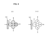
- FIG. 6 schematically illustrates propagation of a stress wave caused in the steel balls 173a by this transmission of the reaction force. As shown in FIG.
- a stress wave (shown by arcuate lines) which is caused in a steel ball A by transmission of the reaction force from the front metal washer 155 spherically propagates through the steel ball A, starting from the contact point (shown by a black dot) between the steel ball A and the front metal washer 155. Then, the stress wave propagates to steel balls B and C which are adjacent to and in contact with the steel ball A, and thereafter likewise propagates to the steel ball D adjacent to the steel balls B and C. By such successive propagation of the stress wave, the steel balls A to D move in a direction of propagation of the stress wave (in the direction shown by the arrow). This state is shown in FIG. 6(II) .
- the steel balls 173a are moved rearward as a whole while each moving in random directions within the case 174.
- Such movement of the steel balls 173a causes the cover plate 177 to move rearward, and then the cover plate 177 pushes and elastically deforms the coil spring 175.
- the random directions of movement of the steel balls 173a correspond to the "different direction” according to this invention, and the state of movement of the steel balls 173a in random directions correspond to the "second state" according to this invention.
- the weight part 163 by forming the weight part 163 using the large number of the steel balls 173a, loss of the reaction force (stress wave) is increased by propagation between the adjacent steel balls 173a, so that the damping effect is increased. Moreover, the stress wave propagates at random in many directions between the large number of the steel balls 173a, so that the reaction force upon the coil spring 175 is reduced. As a result, the life of the coil spring 175 can be increased. Further, the elastic deformation of the coil spring 175 is reduced by reduction of the reaction force upon the coil spring 175, so that the coil spring 175 can be reduced in size by reducing its length in the axial direction of the hammer bit by the reduction of the elastic deformation.
- the electric hammer 101 is described as a representative example of the impact tool.
- the invention is not limited to the hammer drill 101, but can also be applied to a hammer.
- the reaction force is described as being transmitted from the impact bolt 145, but it may be transmitted from the hammer bit 119.
- the motion converting mechanism 113 for converting the rotating output of the driving motor 111 to linear motion is described as being formed by a crank mechanism in order to linearly drive the hammer bit 119, but it is not limited to the crank mechanism.
- a motion converting mechanism utilizing a swash plate that swings in the axial direction can also be used.
Landscapes
- Engineering & Computer Science (AREA)
- Mechanical Engineering (AREA)
- Percussive Tools And Related Accessories (AREA)
Applications Claiming Priority (2)
| Application Number | Priority Date | Filing Date | Title |
|---|---|---|---|
| JP2007237990A JP5100272B2 (ja) | 2007-09-13 | 2007-09-13 | 打撃工具 |
| PCT/JP2008/066561 WO2009035090A1 (fr) | 2007-09-13 | 2008-09-12 | Outil d'impact |
Publications (3)
| Publication Number | Publication Date |
|---|---|
| EP2199031A1 true EP2199031A1 (fr) | 2010-06-23 |
| EP2199031A4 EP2199031A4 (fr) | 2011-11-30 |
| EP2199031B1 EP2199031B1 (fr) | 2013-01-02 |
Family
ID=40452096
Family Applications (1)
| Application Number | Title | Priority Date | Filing Date |
|---|---|---|---|
| EP08830366A Not-in-force EP2199031B1 (fr) | 2007-09-13 | 2008-09-12 | Outil d'impact |
Country Status (4)
| Country | Link |
|---|---|
| EP (1) | EP2199031B1 (fr) |
| JP (1) | JP5100272B2 (fr) |
| CN (1) | CN101801611B (fr) |
| WO (1) | WO2009035090A1 (fr) |
Cited By (2)
| Publication number | Priority date | Publication date | Assignee | Title |
|---|---|---|---|---|
| EP2415564A1 (fr) * | 2010-08-02 | 2012-02-08 | Makita Corporation | Outil à impact |
| EP3822030A1 (fr) * | 2019-11-15 | 2021-05-19 | Hilti Aktiengesellschaft | Marteau perforateur et/ou burin avec agencement de mécanisme de percussion |
Families Citing this family (4)
| Publication number | Priority date | Publication date | Assignee | Title |
|---|---|---|---|---|
| DE102010030026A1 (de) * | 2010-06-14 | 2012-02-23 | Robert Bosch Gmbh | Schlagwerk |
| CN103386669B (zh) * | 2012-05-07 | 2016-03-16 | 苏州宝时得电动工具有限公司 | 电锤 |
| DE102012218882A1 (de) * | 2012-10-17 | 2014-04-17 | Robert Bosch Gmbh | Handwerkzeugmaschinenvorrichtung |
| US12029437B1 (en) | 2020-08-14 | 2024-07-09 | Henry Schein, Inc. | Hand piece for powered osteotome |
Citations (3)
| Publication number | Priority date | Publication date | Assignee | Title |
|---|---|---|---|---|
| EP0064038A1 (fr) * | 1981-04-15 | 1982-11-03 | Atlas Copco Aktiebolag | Procédé et dispositif pour amortir des ondes compressives |
| EP1604785A2 (fr) * | 2004-06-08 | 2005-12-14 | Hitachi Koki Co., Ltd. | Outil de percussion |
| EP1754575A2 (fr) * | 2005-08-19 | 2007-02-21 | Makita Corporation | Outil à impact motorisé |
Family Cites Families (4)
| Publication number | Priority date | Publication date | Assignee | Title |
|---|---|---|---|---|
| JP3556714B2 (ja) * | 1994-11-14 | 2004-08-25 | 株式会社マキタ | 打撃工具の空打ち防止装置 |
| DE19933972A1 (de) * | 1999-07-20 | 2001-01-25 | Bosch Gmbh Robert | Bohr- oder Schlaghammer |
| JP2003175477A (ja) * | 2001-12-12 | 2003-06-24 | Ryobi Ltd | 衝撃工具の衝撃緩和装置 |
| JP4509890B2 (ja) * | 2005-08-19 | 2010-07-21 | 株式会社マキタ | 衝撃式作業工具 |
-
2007
- 2007-09-13 JP JP2007237990A patent/JP5100272B2/ja not_active Expired - Fee Related
-
2008
- 2008-09-12 EP EP08830366A patent/EP2199031B1/fr not_active Not-in-force
- 2008-09-12 WO PCT/JP2008/066561 patent/WO2009035090A1/fr active Application Filing
- 2008-09-12 CN CN2008801069878A patent/CN101801611B/zh not_active Expired - Fee Related
Patent Citations (3)
| Publication number | Priority date | Publication date | Assignee | Title |
|---|---|---|---|---|
| EP0064038A1 (fr) * | 1981-04-15 | 1982-11-03 | Atlas Copco Aktiebolag | Procédé et dispositif pour amortir des ondes compressives |
| EP1604785A2 (fr) * | 2004-06-08 | 2005-12-14 | Hitachi Koki Co., Ltd. | Outil de percussion |
| EP1754575A2 (fr) * | 2005-08-19 | 2007-02-21 | Makita Corporation | Outil à impact motorisé |
Non-Patent Citations (1)
| Title |
|---|
| See also references of WO2009035090A1 * |
Cited By (3)
| Publication number | Priority date | Publication date | Assignee | Title |
|---|---|---|---|---|
| EP2415564A1 (fr) * | 2010-08-02 | 2012-02-08 | Makita Corporation | Outil à impact |
| EP3822030A1 (fr) * | 2019-11-15 | 2021-05-19 | Hilti Aktiengesellschaft | Marteau perforateur et/ou burin avec agencement de mécanisme de percussion |
| WO2021094213A1 (fr) * | 2019-11-15 | 2021-05-20 | Hilti Aktiengesellschaft | Ensemble mécanisme de percussion |
Also Published As
| Publication number | Publication date |
|---|---|
| JP5100272B2 (ja) | 2012-12-19 |
| WO2009035090A1 (fr) | 2009-03-19 |
| EP2199031B1 (fr) | 2013-01-02 |
| CN101801611B (zh) | 2012-09-19 |
| CN101801611A (zh) | 2010-08-11 |
| JP2009066710A (ja) | 2009-04-02 |
| EP2199031A4 (fr) | 2011-11-30 |
Similar Documents
| Publication | Publication Date | Title |
|---|---|---|
| EP1815946B1 (fr) | Outil à impact motorisé | |
| RU2341366C2 (ru) | Инерционно-ударный инструмент (варианты) | |
| EP2159008B1 (fr) | Outil d'impact | |
| US7878265B2 (en) | Impact power tool | |
| EP1992452B1 (fr) | Outil d'impact | |
| EP2199030B1 (fr) | Outil à impact | |
| EP2199031B1 (fr) | Outil d'impact | |
| RU2507060C2 (ru) | Приводной инструмент | |
| JP4509890B2 (ja) | 衝撃式作業工具 | |
| RU2606139C2 (ru) | Приводной инструмент | |
| JP4815362B2 (ja) | 衝撃式作業工具 | |
| JP5022725B2 (ja) | 衝撃式作業工具 | |
| JP2005040880A (ja) | 打撃工具及び打撃工具の空打ち防止機構 | |
| JP4939965B2 (ja) | 衝撃式作業工具 | |
| JP5234414B2 (ja) | 打撃工具 |
Legal Events
| Date | Code | Title | Description |
|---|---|---|---|
| PUAI | Public reference made under article 153(3) epc to a published international application that has entered the european phase |
Free format text: ORIGINAL CODE: 0009012 |
|
| 17P | Request for examination filed |
Effective date: 20100312 |
|
| AK | Designated contracting states |
Kind code of ref document: A1 Designated state(s): AT BE BG CH CY CZ DE DK EE ES FI FR GB GR HR HU IE IS IT LI LT LU LV MC MT NL NO PL PT RO SE SI SK TR |
|
| AX | Request for extension of the european patent |
Extension state: AL BA MK RS |
|
| DAX | Request for extension of the european patent (deleted) | ||
| A4 | Supplementary search report drawn up and despatched |
Effective date: 20111028 |
|
| RIC1 | Information provided on ipc code assigned before grant |
Ipc: B25D 17/24 20060101AFI20111024BHEP |
|
| GRAP | Despatch of communication of intention to grant a patent |
Free format text: ORIGINAL CODE: EPIDOSNIGR1 |
|
| GRAS | Grant fee paid |
Free format text: ORIGINAL CODE: EPIDOSNIGR3 |
|
| GRAA | (expected) grant |
Free format text: ORIGINAL CODE: 0009210 |
|
| AK | Designated contracting states |
Kind code of ref document: B1 Designated state(s): AT BE BG CH CY CZ DE DK EE ES FI FR GB GR HR HU IE IS IT LI LT LU LV MC MT NL NO PL PT RO SE SI SK TR |
|
| REG | Reference to a national code |
Ref country code: GB Ref legal event code: FG4D |
|
| REG | Reference to a national code |
Ref country code: CH Ref legal event code: EP Ref country code: AT Ref legal event code: REF Ref document number: 591326 Country of ref document: AT Kind code of ref document: T Effective date: 20130115 |
|
| REG | Reference to a national code |
Ref country code: IE Ref legal event code: FG4D |
|
| REG | Reference to a national code |
Ref country code: DE Ref legal event code: R096 Ref document number: 602008021423 Country of ref document: DE Effective date: 20130228 |
|
| REG | Reference to a national code |
Ref country code: AT Ref legal event code: MK05 Ref document number: 591326 Country of ref document: AT Kind code of ref document: T Effective date: 20130102 |
|
| REG | Reference to a national code |
Ref country code: NL Ref legal event code: VDEP Effective date: 20130102 |
|
| PG25 | Lapsed in a contracting state [announced via postgrant information from national office to epo] |
Ref country code: SI Free format text: LAPSE BECAUSE OF FAILURE TO SUBMIT A TRANSLATION OF THE DESCRIPTION OR TO PAY THE FEE WITHIN THE PRESCRIBED TIME-LIMIT Effective date: 20130102 |
|
| REG | Reference to a national code |
Ref country code: LT Ref legal event code: MG4D |
|
| PG25 | Lapsed in a contracting state [announced via postgrant information from national office to epo] |
Ref country code: ES Free format text: LAPSE BECAUSE OF FAILURE TO SUBMIT A TRANSLATION OF THE DESCRIPTION OR TO PAY THE FEE WITHIN THE PRESCRIBED TIME-LIMIT Effective date: 20130413 Ref country code: IS Free format text: LAPSE BECAUSE OF FAILURE TO SUBMIT A TRANSLATION OF THE DESCRIPTION OR TO PAY THE FEE WITHIN THE PRESCRIBED TIME-LIMIT Effective date: 20130502 Ref country code: NO Free format text: LAPSE BECAUSE OF FAILURE TO SUBMIT A TRANSLATION OF THE DESCRIPTION OR TO PAY THE FEE WITHIN THE PRESCRIBED TIME-LIMIT Effective date: 20130402 Ref country code: CZ Free format text: LAPSE BECAUSE OF FAILURE TO SUBMIT A TRANSLATION OF THE DESCRIPTION OR TO PAY THE FEE WITHIN THE PRESCRIBED TIME-LIMIT Effective date: 20130102 Ref country code: AT Free format text: LAPSE BECAUSE OF FAILURE TO SUBMIT A TRANSLATION OF THE DESCRIPTION OR TO PAY THE FEE WITHIN THE PRESCRIBED TIME-LIMIT Effective date: 20130102 Ref country code: BE Free format text: LAPSE BECAUSE OF FAILURE TO SUBMIT A TRANSLATION OF THE DESCRIPTION OR TO PAY THE FEE WITHIN THE PRESCRIBED TIME-LIMIT Effective date: 20130102 Ref country code: BG Free format text: LAPSE BECAUSE OF FAILURE TO SUBMIT A TRANSLATION OF THE DESCRIPTION OR TO PAY THE FEE WITHIN THE PRESCRIBED TIME-LIMIT Effective date: 20130402 Ref country code: SE Free format text: LAPSE BECAUSE OF FAILURE TO SUBMIT A TRANSLATION OF THE DESCRIPTION OR TO PAY THE FEE WITHIN THE PRESCRIBED TIME-LIMIT Effective date: 20130102 Ref country code: LT Free format text: LAPSE BECAUSE OF FAILURE TO SUBMIT A TRANSLATION OF THE DESCRIPTION OR TO PAY THE FEE WITHIN THE PRESCRIBED TIME-LIMIT Effective date: 20130102 |
|
| PG25 | Lapsed in a contracting state [announced via postgrant information from national office to epo] |
Ref country code: NL Free format text: LAPSE BECAUSE OF FAILURE TO SUBMIT A TRANSLATION OF THE DESCRIPTION OR TO PAY THE FEE WITHIN THE PRESCRIBED TIME-LIMIT Effective date: 20130102 Ref country code: LV Free format text: LAPSE BECAUSE OF FAILURE TO SUBMIT A TRANSLATION OF THE DESCRIPTION OR TO PAY THE FEE WITHIN THE PRESCRIBED TIME-LIMIT Effective date: 20130102 Ref country code: GR Free format text: LAPSE BECAUSE OF FAILURE TO SUBMIT A TRANSLATION OF THE DESCRIPTION OR TO PAY THE FEE WITHIN THE PRESCRIBED TIME-LIMIT Effective date: 20130403 Ref country code: FI Free format text: LAPSE BECAUSE OF FAILURE TO SUBMIT A TRANSLATION OF THE DESCRIPTION OR TO PAY THE FEE WITHIN THE PRESCRIBED TIME-LIMIT Effective date: 20130102 Ref country code: PL Free format text: LAPSE BECAUSE OF FAILURE TO SUBMIT A TRANSLATION OF THE DESCRIPTION OR TO PAY THE FEE WITHIN THE PRESCRIBED TIME-LIMIT Effective date: 20130102 Ref country code: PT Free format text: LAPSE BECAUSE OF FAILURE TO SUBMIT A TRANSLATION OF THE DESCRIPTION OR TO PAY THE FEE WITHIN THE PRESCRIBED TIME-LIMIT Effective date: 20130502 |
|
| PG25 | Lapsed in a contracting state [announced via postgrant information from national office to epo] |
Ref country code: HR Free format text: LAPSE BECAUSE OF FAILURE TO SUBMIT A TRANSLATION OF THE DESCRIPTION OR TO PAY THE FEE WITHIN THE PRESCRIBED TIME-LIMIT Effective date: 20130102 |
|
| PG25 | Lapsed in a contracting state [announced via postgrant information from national office to epo] |
Ref country code: EE Free format text: LAPSE BECAUSE OF FAILURE TO SUBMIT A TRANSLATION OF THE DESCRIPTION OR TO PAY THE FEE WITHIN THE PRESCRIBED TIME-LIMIT Effective date: 20130102 Ref country code: RO Free format text: LAPSE BECAUSE OF FAILURE TO SUBMIT A TRANSLATION OF THE DESCRIPTION OR TO PAY THE FEE WITHIN THE PRESCRIBED TIME-LIMIT Effective date: 20130102 Ref country code: SK Free format text: LAPSE BECAUSE OF FAILURE TO SUBMIT A TRANSLATION OF THE DESCRIPTION OR TO PAY THE FEE WITHIN THE PRESCRIBED TIME-LIMIT Effective date: 20130102 Ref country code: DK Free format text: LAPSE BECAUSE OF FAILURE TO SUBMIT A TRANSLATION OF THE DESCRIPTION OR TO PAY THE FEE WITHIN THE PRESCRIBED TIME-LIMIT Effective date: 20130102 |
|
| PLBE | No opposition filed within time limit |
Free format text: ORIGINAL CODE: 0009261 |
|
| STAA | Information on the status of an ep patent application or granted ep patent |
Free format text: STATUS: NO OPPOSITION FILED WITHIN TIME LIMIT |
|
| PG25 | Lapsed in a contracting state [announced via postgrant information from national office to epo] |
Ref country code: CY Free format text: LAPSE BECAUSE OF FAILURE TO SUBMIT A TRANSLATION OF THE DESCRIPTION OR TO PAY THE FEE WITHIN THE PRESCRIBED TIME-LIMIT Effective date: 20130102 |
|
| 26N | No opposition filed |
Effective date: 20131003 |
|
| PG25 | Lapsed in a contracting state [announced via postgrant information from national office to epo] |
Ref country code: IT Free format text: LAPSE BECAUSE OF FAILURE TO SUBMIT A TRANSLATION OF THE DESCRIPTION OR TO PAY THE FEE WITHIN THE PRESCRIBED TIME-LIMIT Effective date: 20130102 |
|
| REG | Reference to a national code |
Ref country code: DE Ref legal event code: R097 Ref document number: 602008021423 Country of ref document: DE Effective date: 20131003 |
|
| PG25 | Lapsed in a contracting state [announced via postgrant information from national office to epo] |
Ref country code: MC Free format text: LAPSE BECAUSE OF FAILURE TO SUBMIT A TRANSLATION OF THE DESCRIPTION OR TO PAY THE FEE WITHIN THE PRESCRIBED TIME-LIMIT Effective date: 20130102 |
|
| REG | Reference to a national code |
Ref country code: CH Ref legal event code: PL |
|
| REG | Reference to a national code |
Ref country code: IE Ref legal event code: MM4A |
|
| PG25 | Lapsed in a contracting state [announced via postgrant information from national office to epo] |
Ref country code: CH Free format text: LAPSE BECAUSE OF NON-PAYMENT OF DUE FEES Effective date: 20130930 Ref country code: IE Free format text: LAPSE BECAUSE OF NON-PAYMENT OF DUE FEES Effective date: 20130912 Ref country code: LI Free format text: LAPSE BECAUSE OF NON-PAYMENT OF DUE FEES Effective date: 20130930 |
|
| PG25 | Lapsed in a contracting state [announced via postgrant information from national office to epo] |
Ref country code: MT Free format text: LAPSE BECAUSE OF FAILURE TO SUBMIT A TRANSLATION OF THE DESCRIPTION OR TO PAY THE FEE WITHIN THE PRESCRIBED TIME-LIMIT Effective date: 20130102 Ref country code: TR Free format text: LAPSE BECAUSE OF FAILURE TO SUBMIT A TRANSLATION OF THE DESCRIPTION OR TO PAY THE FEE WITHIN THE PRESCRIBED TIME-LIMIT Effective date: 20130102 |
|
| PG25 | Lapsed in a contracting state [announced via postgrant information from national office to epo] |
Ref country code: HU Free format text: LAPSE BECAUSE OF FAILURE TO SUBMIT A TRANSLATION OF THE DESCRIPTION OR TO PAY THE FEE WITHIN THE PRESCRIBED TIME-LIMIT; INVALID AB INITIO Effective date: 20080912 Ref country code: LU Free format text: LAPSE BECAUSE OF NON-PAYMENT OF DUE FEES Effective date: 20130912 |
|
| REG | Reference to a national code |
Ref country code: FR Ref legal event code: PLFP Year of fee payment: 9 |
|
| REG | Reference to a national code |
Ref country code: FR Ref legal event code: PLFP Year of fee payment: 10 |
|
| REG | Reference to a national code |
Ref country code: FR Ref legal event code: PLFP Year of fee payment: 11 |
|
| PGFP | Annual fee paid to national office [announced via postgrant information from national office to epo] |
Ref country code: GB Payment date: 20200902 Year of fee payment: 13 Ref country code: FR Payment date: 20200812 Year of fee payment: 13 Ref country code: DE Payment date: 20200901 Year of fee payment: 13 |
|
| REG | Reference to a national code |
Ref country code: DE Ref legal event code: R119 Ref document number: 602008021423 Country of ref document: DE |
|
| GBPC | Gb: european patent ceased through non-payment of renewal fee |
Effective date: 20210912 |
|
| PG25 | Lapsed in a contracting state [announced via postgrant information from national office to epo] |
Ref country code: GB Free format text: LAPSE BECAUSE OF NON-PAYMENT OF DUE FEES Effective date: 20210912 Ref country code: FR Free format text: LAPSE BECAUSE OF NON-PAYMENT OF DUE FEES Effective date: 20210930 Ref country code: DE Free format text: LAPSE BECAUSE OF NON-PAYMENT OF DUE FEES Effective date: 20220401 |