EP2197606B1 - Method for producing hollow forged parts - Google Patents
Method for producing hollow forged parts Download PDFInfo
- Publication number
- EP2197606B1 EP2197606B1 EP08840711A EP08840711A EP2197606B1 EP 2197606 B1 EP2197606 B1 EP 2197606B1 EP 08840711 A EP08840711 A EP 08840711A EP 08840711 A EP08840711 A EP 08840711A EP 2197606 B1 EP2197606 B1 EP 2197606B1
- Authority
- EP
- European Patent Office
- Prior art keywords
- core
- blank
- forging
- gas discharge
- positioning
- Prior art date
- Legal status (The legal status is an assumption and is not a legal conclusion. Google has not performed a legal analysis and makes no representation as to the accuracy of the status listed.)
- Ceased
Links
- 238000004519 manufacturing process Methods 0.000 title claims abstract description 13
- 238000005242 forging Methods 0.000 claims abstract description 33
- 229910052751 metal Inorganic materials 0.000 claims abstract description 12
- 239000002184 metal Substances 0.000 claims abstract description 12
- 239000000463 material Substances 0.000 claims abstract description 10
- 238000005266 casting Methods 0.000 claims abstract description 6
- 238000007789 sealing Methods 0.000 claims abstract description 5
- 238000000034 method Methods 0.000 claims description 37
- 239000011162 core material Substances 0.000 description 53
- 239000007789 gas Substances 0.000 description 22
- 238000000465 moulding Methods 0.000 description 7
- 239000011347 resin Substances 0.000 description 3
- 229920005989 resin Polymers 0.000 description 3
- 230000008901 benefit Effects 0.000 description 2
- 230000007547 defect Effects 0.000 description 2
- 238000010438 heat treatment Methods 0.000 description 2
- 239000011159 matrix material Substances 0.000 description 2
- 239000004576 sand Substances 0.000 description 2
- 229910000838 Al alloy Inorganic materials 0.000 description 1
- 230000005540 biological transmission Effects 0.000 description 1
- 239000000919 ceramic Substances 0.000 description 1
- 239000011248 coating agent Substances 0.000 description 1
- 238000000576 coating method Methods 0.000 description 1
- 238000002485 combustion reaction Methods 0.000 description 1
- 230000006835 compression Effects 0.000 description 1
- 238000007906 compression Methods 0.000 description 1
- 239000000470 constituent Substances 0.000 description 1
- 238000005553 drilling Methods 0.000 description 1
- 229910001234 light alloy Inorganic materials 0.000 description 1
- 239000004033 plastic Substances 0.000 description 1
- 239000002994 raw material Substances 0.000 description 1
- 150000003839 salts Chemical group 0.000 description 1
- 230000003068 static effect Effects 0.000 description 1
- 239000000725 suspension Substances 0.000 description 1
- 230000002459 sustained effect Effects 0.000 description 1
Images


Classifications
-
- B—PERFORMING OPERATIONS; TRANSPORTING
- B21—MECHANICAL METAL-WORKING WITHOUT ESSENTIALLY REMOVING MATERIAL; PUNCHING METAL
- B21K—MAKING FORGED OR PRESSED METAL PRODUCTS, e.g. HORSE-SHOES, RIVETS, BOLTS OR WHEELS
- B21K21/00—Making hollow articles not covered by a single preceding sub-group
-
- B—PERFORMING OPERATIONS; TRANSPORTING
- B21—MECHANICAL METAL-WORKING WITHOUT ESSENTIALLY REMOVING MATERIAL; PUNCHING METAL
- B21J—FORGING; HAMMERING; PRESSING METAL; RIVETING; FORGE FURNACES
- B21J5/00—Methods for forging, hammering, or pressing; Special equipment or accessories therefor
- B21J5/002—Hybrid process, e.g. forging following casting
-
- B—PERFORMING OPERATIONS; TRANSPORTING
- B21—MECHANICAL METAL-WORKING WITHOUT ESSENTIALLY REMOVING MATERIAL; PUNCHING METAL
- B21J—FORGING; HAMMERING; PRESSING METAL; RIVETING; FORGE FURNACES
- B21J5/00—Methods for forging, hammering, or pressing; Special equipment or accessories therefor
- B21J5/02—Die forging; Trimming by making use of special dies ; Punching during forging
-
- B—PERFORMING OPERATIONS; TRANSPORTING
- B22—CASTING; POWDER METALLURGY
- B22C—FOUNDRY MOULDING
- B22C9/00—Moulds or cores; Moulding processes
- B22C9/10—Cores; Manufacture or installation of cores
- B22C9/106—Vented or reinforced cores
Definitions
- the present invention relates to the technical field of manufacturing metal parts subjected to a forging operation.
- the object of the invention finds particularly advantageous applications for producing metal parts such as aluminum alloy in order to produce parts for the field for example of the cycle or automobile such as connecting rods, suspension wishbones, pivots, transmission parts, engine mounts or any other ground connection parts.
- the document EP 0 850 825 proposes to make a core material lost to form the hollow part of a bicycle pedal crank.
- This core is extended by a support portion for positioning the support within a casting mold in which a metal is cast. Before a subsequent forging operation, the support portion of the core and the portion of the core defining the receiving bore are removed. Even if such a technique reduces the amount of material used, this technique is unsatisfactory in practice because it does not ensure the good stability of the core during the forging operation. In addition, this technique requires the removal of a portion of the core prior to the forging operation. In addition to the disadvantages of this operation, It can not be ruled out that core debris can be found on forging tools, which can cause surface defects on the part.
- the present invention therefore aims to overcome the disadvantages mentioned above by providing a method to benefit from the advantages of the forging process of a part while allowing to obtain a piece of optimized weight at a reduced cost.
- Another object of the invention is to provide a method for producing a hollow forged part whose dimensional characteristics are perfectly controlled.
- Another object of the invention is to provide a method for simply and inexpensively producing a hollow forging without surface defects likely to appear during the forging operation.
- the method according to the invention aims at producing a hollow forged part.
- the method consists in providing the core with at least one gas evacuation duct.
- the method consists in ensuring the positioning of the core in the mold by means of the gas evacuation duct.
- the method consists in sealing the blank by closing off each gas discharge duct.
- the method consists in closing off each gas discharge duct with the aid of a stiffening element filling said duct.
- the method consists in positioning the gas evacuation pipe in the core in a place intended to constitute a housing for the part.
- the method consists in positioning the gas evacuation pipe so that it extends projecting on either side of the core so as to constitute a housing through the room.
- the method consists of preheating the blank before it is forged.
- the object of the invention is to ensure the manufacture of a hollow forged part 1 .
- the piece 1 is a hoe comprising a body or arm 2 provided at each end of a head 3 of cylindrical shape.
- Each head 3 is provided with a through bore 4 opening on two opposite lateral faces 5.
- the bores 4 extend along axes parallel to each other and perpendicular to the direction of extension of the arm 2. that this is clear from the Fig. 1 , the body 2 is hollow insofar as it has a recess 7 opening into the bores 4 of the two heads 3.
- the piece 1 is obtained according to the manufacturing method according to the invention which aims to provide a molding operation on a core of lost material to obtain a blank then subjected to a forging operation.
- the method of the invention is to provide a core 10 in a lost material whose external shape corresponds to the inner shape of the workpiece 1 to obtain deformation near sustained during a subsequent operation of forging which will be described precisely in the following description.
- the core 10 is made according to all the known methods using lost materials.
- the core 10 is a salt core, a sand core made using a cold or hot box or "croning".
- the core consists of sand and resin.
- the core 10 is full.
- the core is adapted to have sufficient mechanical strength during the subsequent forging operation.
- the core 10 is adapted to withstand the stresses experienced during the forging operation.
- the core 10 is provided with at least one gas evacuation duct 11.
- the core 10 is provided with two gas evacuation conduits 11.
- Each gas evacuation duct is made for example by a tube 11 pierced with holes 12 and inserted at least partly inside the core.
- Each duct 11 protrudes from the core 10.
- These ducts 11 are intended to evacuate the gases out of the mold, during the molding operation. These gases can come from the combustion of the resins forming part of the core 10.
- the outer surface of the core 10 can be made impermeable, for example by coating to force the gases to exit through the conduits. 11.
- each gas evacuation duct 11 is positioned in the core 10 in a place intended to constitute the bore 4 for the part.
- each duct 11 is placed so that its axis of symmetry coincides with the axis of the bore 4 in which the duct is placed.
- each gas evacuation duct 11 ensures the positioning of the core 10 in the mold during the molding operation.
- each gas evacuation duct 11 protrudes on either side of the core, that is to say from the lateral faces 5.
- the method consists in providing a molding operation on the core 10 by means of a conventional casting process.
- This foundry operation will not be described in detail because it is part of the technical knowledge of the skilled person and it can be implemented by any known foundry technique.
- the core 10 and as it stands out more precisely from the Fig.4 is intended to be placed in a mold 15 of which only the lower part has been illustrated at the Fig. 4 .
- the gas discharge ducts 11 serve to position the core 10 inside the mold 15.
- the mold is of any type and may be a sand mold, a metal shell or any another molding method for producing a preform to be forged.
- the method therefore consists in ensuring the casting of a metal around the core 10 to completely envelop it in order to obtain a blank 18 as illustrated in FIG. Fig. 5 .
- the core 10 is completely wrapped except the exhaust ducts 11 when they are present.
- the method according to the invention aims to seal the blank 18 so that the core 10 is completely isolated vis-à-vis the external environment.
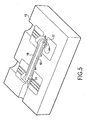
- the sealing of the blank 18 is ensured by sealing each gas evacuation duct 11 with a closure element 20 of all types ( Fig. 6 ) .
- This closure member 20 can be made in any suitable manner by a metal plug, resin, plastic or ceramic. In this way, the core 10 is not in contact with the air.
- the method consists in closing off each gas evacuation duct 11 with the aid of a stiffening element 20 filling the duct.
- this element 20 may be a rod or a metal shaft completely filling each gas discharge duct 11. This element makes it possible to stiffen and seal each gas evacuation duct 11.
- the method according to the invention is then to ensure the forging of the blank 18 to obtain the piece to the desired shape.
- This forging operation is performed either cold or hot.
- the blank 18 is preheated before being placed as illustrated in FIG. Fig. 7 , In a matrix 22 of a forging press.
- the blank 18 is thus positioned between the two dies of a forging press of all known types.
- the core 10 still present in the blank 18, makes it possible to ensure against-pressure avoiding a collapse of the part at the recess 7, during the striking operation.
- the core 10 thus ensures a level of compression adapted to obtain good mechanical strength characteristics. It should be noted that the presence of the metal pins 20 inside the core 10 also contributes to the strength of the core.
- the piece 1 is removed from the dies as illustrated in FIG. Fig. 8 . If the piece 1 has a burr 22 due to the forging operation, then this burr 22 is removed.
- the method according to the invention then consists in ensuring the breaking of the core 10 of the part 1 to obtain the hollow forging.
- This stripping operation may be performed by any appropriate means such as drilling, vibration and / or heat treatment to remove the entire core 10. For example, it may be envisaged to drill at the heads 3 in order to get bores 4 ( Fig. 9 ) and a heat treatment to remove the core located in the arm 2 to obtain the recess 7. After the total removal of the core 10, the hollow part 1 is obtained ( Fig. 1 ).
- the method according to the invention makes it possible to obtain a hollow forged part.
- the part 1 is a connecting rod. It is clear that the object of the invention can be implemented for different parts with various shapes with one or more opening recesses.
Landscapes
- Engineering & Computer Science (AREA)
- Mechanical Engineering (AREA)
- Forging (AREA)
- Molds, Cores, And Manufacturing Methods Thereof (AREA)
Abstract
Description
La présente invention concerne le domaine technique de la fabrication de pièces en métal soumis à une opération de forgeage.The present invention relates to the technical field of manufacturing metal parts subjected to a forging operation.
L'objet de l'invention trouve des applications particulièrement avantageuses pour réaliser des pièces en métal tels qu'en alliage d'aluminium en vue de réaliser des pièces pour le domaine par exemple du cycle ou de l'automobile tels que des bielles, des triangles de suspension, des pivots, des pièces de transmission, des supports moteurs ou toutes autres pièces de liaison au sol.The object of the invention finds particularly advantageous applications for producing metal parts such as aluminum alloy in order to produce parts for the field for example of the cycle or automobile such as connecting rods, suspension wishbones, pivots, transmission parts, engine mounts or any other ground connection parts.
Dans l'état de la technique, il est connu de réaliser une pièce par les techniques de forgeage. Ce procédé consiste à réaliser une ébauche en métal et à la placer après l'avoir éventuellement réchauffée, entre deux gravures d'une matrice. Ces deux gravures sont actionnées par une presse l'une contre l'autre pour exercer sur l'ébauche un travail de déformation tout en garantissant un bon état de surface. Un tel procédé permet d'obtenir des pièces avec une bonne résistance mécanique (statique et dynamique) et un respect des tolérances géométriques.In the state of the art, it is known to produce a part by forging techniques. This method consists of making a metal blank and placing it after having possibly heated it between two engravings of a matrix. These two engravings are actuated by a press against each other to exert on the blank a work of deformation while ensuring a good surface condition. Such a method makes it possible to obtain parts with a good mechanical resistance (static and dynamic) and a respect of the geometrical tolerances.
Toutefois, cette technique conduit à l'obtention de pièces massives et relativement lourdes même si le matériau utilisé est un alliage léger. Dans le même sens, compte tenu du prix des matières premières et notamment du matériau constitutif de la pièce, il s'ensuit un coût de la pièce relativement élevé.However, this technique leads to the production of massive and relatively heavy parts even if the material used is a light alloy. In the same sense, given the price of raw materials and in particular the constituent material of the part, it follows a relatively high cost of the part.
Pour tenter de remédier à ces inconvénients, le document
La présente invention vise donc à remédier aux inconvénients énoncés ci-dessus en proposant un procédé permettant de bénéficier des avantages du procédé de forgeage d'une pièce tout en permettant d'obtenir une pièce de poids optimisé à un coût réduit.The present invention therefore aims to overcome the disadvantages mentioned above by providing a method to benefit from the advantages of the forging process of a part while allowing to obtain a piece of optimized weight at a reduced cost.
Un autre objet de l'invention vise à proposer un procédé permettant de réaliser une pièce forgée creuse dont les caractéristiques dimensionnelles sont parfaitement maîtrisées.Another object of the invention is to provide a method for producing a hollow forged part whose dimensional characteristics are perfectly controlled.
Un autre objet de l'invention vise à offrir un procédé permettant de réaliser simplement et à faible coût une pièce forgée creuse sans défaut de surface susceptible d'apparaître lors de l'opération de forgeage.Another object of the invention is to provide a method for simply and inexpensively producing a hollow forging without surface defects likely to appear during the forging operation.
Pour atteindre un tel objectif, le procédé selon l'invention vise à réaliser une pièce forgée creuse.To achieve such an objective, the method according to the invention aims at producing a hollow forged part.
L'objet de l'invention vise donc à proposer un procédé de fabrication de pièces forgées creuses comportant les étapes suivantes :
- réalisation d'un noyau en matériau perdu dont la forme correspond à la forme intérieure de la pièce à obtenir, à la déformation près subie lors du forgeage,
- positionnement du noyau dans un moule de fonderie,
- moulage d'un métal autour du noyau pour envelopper complètement le noyau en vue d'obtenir une ébauche,
- étancher l'ébauche de sorte que le noyau se trouve complètement isolé vis-à-vis de l'extérieur,
- forgeage de l'ébauche afin d'obtenir la pièce à la forme souhaitée,
- et débourrage du noyau de la pièce pour obtenir la pièce forgée creuse.
- production of a core of lost material whose shape corresponds to the inner shape of the part to be obtained, to the deformation undergone during the forging,
- positioning the core in a foundry mold,
- molding a metal around the core to completely envelop the core to obtain a blank,
- seal the blank so that the core is completely isolated vis-à-vis the outside,
- forging the blank to obtain the part to the desired shape,
- and unclogging the core of the piece to obtain the hollow forging.
Selon une caractéristique avantageuse de réalisation, le procédé consiste à munir le noyau d'au moins un conduit d'évacuation de gaz.According to an advantageous embodiment characteristic, the method consists in providing the core with at least one gas evacuation duct.
Avantageusement, le procédé consiste à assurer le positionnement du noyau dans le moule à l'aide du conduit d'évacuation de gaz.Advantageously, the method consists in ensuring the positioning of the core in the mold by means of the gas evacuation duct.
Selon un mode de réalisation, le procédé consiste à assurer l'étanchéité de l'ébauche en obturant chaque conduit d'évacuation de gaz.According to one embodiment, the method consists in sealing the blank by closing off each gas discharge duct.
Selon une variante préférée de réalisation, le procédé consiste à obturer chaque conduit d'évacuation de gaz à l'aide d'un élément de rigidification remplissant ledit conduit.According to a preferred embodiment, the method consists in closing off each gas discharge duct with the aid of a stiffening element filling said duct.
De préférence, le procédé consiste à positionner le conduit d'évacuation de gaz dans le noyau en un lieu destiné à constituer un logement pour la pièce.Preferably, the method consists in positioning the gas evacuation pipe in the core in a place intended to constitute a housing for the part.
Selon un exemple de réalisation, le procédé consiste à positionner le conduit d'évacuation de gaz pour qu'il s'étende en saillie de part et d'autre du noyau de manière à constituer un logement traversant dans la pièce.According to an exemplary embodiment, the method consists in positioning the gas evacuation pipe so that it extends projecting on either side of the core so as to constitute a housing through the room.
Selon une variante de réalisation, le procédé consiste à assurer le préchauffage de l'ébauche avant son forgeage.According to an alternative embodiment, the method consists of preheating the blank before it is forged.
Diverses autres caractéristiques ressortent de la description faite ci-dessous en référence aux dessins annexés qui montrent, à titre d'exemples non limitatifs, des formes de réalisation de l'objet de l'invention.
- La
Figure 1 est une vue en perspective en écorché présentant un exemple de réalisation d'une pièce obtenue par le procédé de fabrication conforme à l'invention. - La
Figure 2 illustre un noyau en partie écorché mis en oeuvre dans une étape du procédé selon l'invention. - La
Figure 3 est une vue en perspective écorchée montrant un noyau pourvu de conduits d'évacuation de gaz. - La
Figure 4 illustre la mise en place dans un moule, d'un noyau tel qu'illustré à laFig. 3 . - La
Figure 5 est une vue en perspective d'une ébauche obtenue après la coulée d'un matériau dans un moule illustré à laFig. 4 . - La
Figure 6 illustre une ébauche obtenue après l'opération de moulage et dont les conduits d'évacuation de gaz sont étanchés. - La
Figure 7 est une vue d'une matrice inférieure de forgeage dans laquelle est positionnée l'ébauche illustrée à laFig. 6 . - La
Figure 8 illustre une vue en perspective en partie écorchée de la pièce obtenue après l'opération de forgeage. - La
Figure 9 illustre une vue en perspective en partie arrachée de la pièce dont une partie du noyau a été percée.
- The
Figure 1 is a broken perspective view showing an exemplary embodiment of a part obtained by the manufacturing method according to the invention. - The
Figure 2 illustrates a partially cut kernel implemented in a step of the method according to the invention. - The
Figure 3 is a cutaway perspective view showing a core provided with gas exhaust ducts. - The
Figure 4 illustrates the placement in a mold of a core as illustrated inFig. 3 . - The
Figure 5 is a perspective view of a blank obtained after the casting of a material in a mold illustrated in FIG.Fig. 4 . - The
Figure 6 illustrates a blank obtained after the molding operation and whose gas evacuation ducts are sealed. - The
Figure 7 is a view of a lower forging die in which is positioned the blank shown in FIG.Fig. 6 . - The
Figure 8 illustrates a partly broken perspective view of the part obtained after the forging operation. - The
Figure 9 illustrates a partly cutaway perspective view of the part of which part of the core has been pierced.
L'objet de l'invention vise à assurer la fabrication d'une pièce 1 forgée creuse. Dans l'exemple de réalisation illustrée à la
La pièce 1 est obtenue selon le procédé de fabrication conforme à l'invention qui vise à assurer une opération de moulage sur un noyau en matériau perdu afin d'obtenir une ébauche soumise ensuite à une opération de forgeage.The
Tel que cela ressort plus précisément de la
Selon une caractéristique préférée de réalisation, le noyau 10 est plein. Bien entendu, il peut être envisagé de réaliser un noyau 10 à caractère creux. Dans ce cas, le noyau est adapté pour présenter une résistance mécanique suffisante lors de l'opération ultérieure de forgeage. En d'autres termes, le noyau 10 est adapté pour résister aux sollicitations subies lors de l'opération de forgeage.According to a preferred embodiment, the
Selon une variante préférée de réalisation, le noyau 10 est pourvu d'au moins un conduit d'évacuation de gaz 11. Dans l'exemple illustré à la
Selon une caractéristique préférée de réalisation, chaque conduit d'évacuation de gaz 11 est positionné dans le noyau 10 en un lieu destiné à constituer l'alésage 4 pour la pièce. En d'autres termes, chaque conduit 11 est placé de sorte que son axe de symétrie se trouve confondu avec l'axe de l'alésage 4 dans lequel le conduit est placé.According to a preferred embodiment, each
Selon une caractéristique préférée de réalisation, chaque conduit d'évacuation de gaz 11 assure le positionnement du noyau 10 dans le moule lors de l'opération de moulage. Dans l'exemple illustré, chaque conduit d'évacuation de gaz 11 s'étend en saillie de part et d'autre du noyau, c'est-à-dire à partir des faces latérales 5. According to a preferred embodiment, each
Conformément à l'invention, le procédé consiste à assurer une opération de moulage sur le noyau 10 à l'aide d'un procédé de fonderie classique. Cette opération de fonderie ne sera pas décrite en détail car elle fait partie des connaissances techniques de l'homme du métier et elle peut être mise en oeuvre par n'importe quelle technique de fonderie connue.According to the invention, the method consists in providing a molding operation on the
Ainsi, le noyau 10 et tel que cela ressort plus précisément de la
Le procédé consiste donc à assurer la coulée d'un métal autour du noyau 10 pour l'envelopper complètement en vue d'obtenir une ébauche 18 telle qu'illustrée à la
Le procédé selon l'invention vise à étancher l'ébauche 18 de sorte que le noyau 10 se trouve complètement isolé vis-à-vis de l'environnement extérieur. Dans l'exemple de réalisation illustré, l'étanchéité de l'ébauche 18 est assurée en obturant chaque conduit d'évacuation de gaz 11 par un élément d'obturation 20 de tous types (
Selon une caractéristique préférée de réalisation, le procédé consiste à obturer chaque conduit d'évacuation de gaz 11 à l'aide d'un élément de rigidification 20 remplissant le conduit. Par exemple, cet élément 20 peut être une tige ou un axe métallique remplissant complètement chaque conduit d'évacuation de gaz 11. Cet élément permet de rigidifier et d'étancher chaque conduit d'évacuation de gaz 11. According to a preferred embodiment, the method consists in closing off each
Le procédé selon l'invention consiste ensuite à assurer le forgeage de l'ébauche 18 afin d'obtenir la pièce à la forme souhaitée.The method according to the invention is then to ensure the forging of the blank 18 to obtain the piece to the desired shape.
Cette opération de forgeage est réalisée soit à froid, soit à chaud. Dans le cas du forgeage à chaud, l'ébauche 18 est préchauffée avant d'être placée comme illustrée à la
Après l'opération de forgeage, la pièce 1 est enlevée des matrices comme illustrée à la
Le procédé selon l'invention consiste ensuite à assurer le débourrage du noyau 10 de la pièce 1 pour obtenir la pièce forgée creuse. Cette opération de débourrage peut être réalisée par tout moyen approprié tel que perçage, vibrations et/ou traitement thermique permettant d'enlever la totalité du noyau 10. Par exemple, il peut être envisagé de réaliser un perçage au niveau des têtes 3 afin d'obtenir des alésages 4 (
Tel que cela ressort de la description qui précède, le procédé selon l'invention permet d'obtenir une pièce forgée creuse. Dans l'exemple illustré, la pièce 1 est une bielle. Il est clair que l'objet de l'invention peut être mis en oeuvre pour différentes pièces avec des formes variées avec un ou plusieurs évidements débouchants.As is apparent from the foregoing description, the method according to the invention makes it possible to obtain a hollow forged part. In the example shown, the
Claims (8)
- A method for manufacturing hollow forged parts (1), characterized in that it includes the following steps:- making a core (10) in lost material, the shape of which corresponds to the inner shape of the part to be obtained, to within the deformation undergone during forging,- positioning the core (10) in a foundry mold,- casting a metal around the core (10) in order to completely encase the core with view to obtaining a blank (18),- sealing the blank (18), so that the core (10) is found completely isolated with regard to the outside,- forging the blank (18) in order to obtain the part with the desired shape,- and removing the core (10) from the part in order to obtain the hollow forged part (1).
- The method according to claim 1, characterized in that it consists of providing the core (10) with at least one a gas discharge conduit (11).
- The method according to claim 2, characterized in that it consists of ensuring the positioning of the core (10) in the mold by means of the gas discharge conduit (11).
- The method according to claim 2, characterized in that it consists of ensuring the seal of the blank (18) by obturating each gas discharge conduit (11).
- The method according to claim 4, characterized in that it consists of obturating each gas discharge conduit (11) with a stiffening member (20) are filling said conduit.
- The method according to one of claims 2 to 5, characterized in that it consists of positioning the gas discharge conduit (11) in the core (10) in a location intended to form a housing (4) for the part.
- The method according to claim 6, characterized in that it consists of positioning the gas discharge conduit (11), so that it extends protruding on either side of the core so as to form a through-housing (4) in the part.
- The method according to claim 1, characterized in that it consists of ensuring the preheating of the blank (18) before its forging.
Applications Claiming Priority (2)
| Application Number | Priority Date | Filing Date | Title |
|---|---|---|---|
| FR0757922A FR2921574B1 (en) | 2007-09-28 | 2007-09-28 | METHOD FOR MANUFACTURING HOLLOW FORGED PARTS AND PARTS THUS OBTAINED |
| PCT/FR2008/051720 WO2009050382A2 (en) | 2007-09-28 | 2008-09-26 | Method for producing hollow forged parts and parts thus obtained |
Publications (2)
| Publication Number | Publication Date |
|---|---|
| EP2197606A2 EP2197606A2 (en) | 2010-06-23 |
| EP2197606B1 true EP2197606B1 (en) | 2011-09-21 |
Family
ID=39321470
Family Applications (1)
| Application Number | Title | Priority Date | Filing Date |
|---|---|---|---|
| EP08840711A Ceased EP2197606B1 (en) | 2007-09-28 | 2008-09-26 | Method for producing hollow forged parts |
Country Status (5)
| Country | Link |
|---|---|
| EP (1) | EP2197606B1 (en) |
| CN (1) | CN101808762B (en) |
| AT (1) | ATE525151T1 (en) |
| FR (1) | FR2921574B1 (en) |
| WO (1) | WO2009050382A2 (en) |
Families Citing this family (4)
| Publication number | Priority date | Publication date | Assignee | Title |
|---|---|---|---|---|
| FR2958193B1 (en) * | 2010-04-06 | 2012-06-29 | Saint Jean Ind | PROCESS FOR MANUFACTURING LIGHT ALLOY FORGED PARTS INCORPORATING FULL OR DRAWN THICKNESS SECTIONS |
| FR2969516B1 (en) | 2010-12-23 | 2013-08-16 | Saint Jean Ind | PROCESS FOR THE PRODUCTION OF SALT CORE BY ISOSTATIC COMPACTION UILIZABLE IN FOUNDRY OR FOUNDRY-FORGING |
| CN106925720A (en) * | 2017-04-17 | 2017-07-07 | 大连旅桑实业有限公司 | A kind of sand mold mould for casting arm type casting long |
| CN111842749A (en) * | 2020-07-13 | 2020-10-30 | 中国船舶工业集团公司第七0八研究所 | Manufacturing method of universal marine steel structure |
Family Cites Families (8)
| Publication number | Priority date | Publication date | Assignee | Title |
|---|---|---|---|---|
| DE1938526A1 (en) * | 1969-07-29 | 1971-02-18 | Ideal Standard | Sand core with ventilation channels |
| JPS5554259A (en) * | 1978-10-18 | 1980-04-21 | Hitachi Metals Ltd | Mold casting method |
| JPS56114554A (en) * | 1980-02-13 | 1981-09-09 | Hitachi Metals Ltd | Mold |
| JPS6076249A (en) * | 1983-09-30 | 1985-04-30 | Toyota Motor Corp | Sand core |
| JPH05146841A (en) * | 1991-11-27 | 1993-06-15 | Toyota Motor Corp | Forging method |
| JP3149374B2 (en) * | 1996-12-27 | 2001-03-26 | 株式会社シマノ | Bicycle hollow crank and manufacturing method thereof |
| JP3248676B2 (en) * | 1996-12-27 | 2002-01-21 | 株式会社シマノ | Bicycle crank and manufacturing method thereof |
| CN1057716C (en) * | 1997-02-18 | 2000-10-25 | 曾绍谦 | Mould core device capable of simple taking out mandrel for cold forging and use method thereof |
-
2007
- 2007-09-28 FR FR0757922A patent/FR2921574B1/en not_active Expired - Fee Related
-
2008
- 2008-09-26 CN CN200880107675.9A patent/CN101808762B/en not_active Expired - Fee Related
- 2008-09-26 EP EP08840711A patent/EP2197606B1/en not_active Ceased
- 2008-09-26 WO PCT/FR2008/051720 patent/WO2009050382A2/en active Application Filing
- 2008-09-26 AT AT08840711T patent/ATE525151T1/en not_active IP Right Cessation
Also Published As
| Publication number | Publication date |
|---|---|
| WO2009050382A3 (en) | 2009-06-11 |
| FR2921574B1 (en) | 2010-04-16 |
| CN101808762B (en) | 2013-02-20 |
| CN101808762A (en) | 2010-08-18 |
| EP2197606A2 (en) | 2010-06-23 |
| ATE525151T1 (en) | 2011-10-15 |
| FR2921574A1 (en) | 2009-04-03 |
| WO2009050382A2 (en) | 2009-04-23 |
Similar Documents
| Publication | Publication Date | Title |
|---|---|---|
| EP2585721B1 (en) | Process of manufacturing the metallic shield of a turbomachine blade | |
| EP2197606B1 (en) | Method for producing hollow forged parts | |
| EP2555886B1 (en) | Method for the manufacture of forged light alloy workpieces with full and hollow cross-sections | |
| CA2954024C (en) | Method for manufacturing a two-component blade for a gas turbine engine and blade obtained by such a method | |
| EP1693127B1 (en) | Method of upsetting a metallic billet and jacket - top set for carrying out said method | |
| CA2493445C (en) | Reinforced composite mechanical component, and method for making same | |
| FR2572394A1 (en) | METHOD FOR MANUFACTURING A CERAMIC TURBINE RING INTEGRATED WITH AN ANNULAR METAL SUPPORT | |
| WO2017060600A1 (en) | Method for additive manufacturing comprising a step of hot isostatic pressing | |
| WO2009112725A1 (en) | Method for making metal plates, alone or in the form of a homogenous alloy, by centrifuging | |
| CA2887335C (en) | Method for manufacturing at least one metal turbine engine part | |
| CH622857A5 (en) | ||
| FR3073760A1 (en) | Insert element and method of manufacture | |
| FR2874339A1 (en) | Primary part manufacturing method for e.g. turbomachine, involves finish forging primary part using die by press, where forging is effectuated in two successive and complementary stages for two portions of primary part | |
| EP0598664B1 (en) | Connecting-rod in two parts which are assembled on each other | |
| FR2888288A3 (en) | IC engine cylinder head with partitioned inlet duct has partition made from same material as head during casting process | |
| FR2828122A1 (en) | METHOD AND APPARATUS FOR MANUFACTURING A BOOSTER COMPRESSOR ROTOR | |
| EP0586314B1 (en) | Method of making pieces of casting alloys with reinforced parts | |
| FR2474908A1 (en) | CLOSED CHAMBER EXTRUSION METHOD AND DEVICE FOR CONFIGURING A METAL ROD IN A TULIP-SHAPED WORKPIECE | |
| EP1470889A1 (en) | Method of manufacturing a piston, tool for carrying out said method and piston thus obtained | |
| FR3032898A1 (en) | METHOD OF FORGING AT HIGH TEMPERATURE OF A PREFORMED METAL PIECE | |
| FR3036048A1 (en) | FOUNDRY METHOD WITH PERMANENT MOLD | |
| FR2748677A1 (en) | Method of cold forging motor vehicle clutch components | |
| BE499042A (en) | ||
| FR2662471A1 (en) | Method for making spark plug wells in a cylinder head of an internal combustion engine, and set of elements intended to form at least one such spark plug well | |
| FR3108539A1 (en) | DIRECTED SOLIDIFICATION PROCESS FOR METAL ALLOYS AND MODEL IN ELIMINABLE MATERIAL FOR THE PROCESS |
Legal Events
| Date | Code | Title | Description |
|---|---|---|---|
| PUAI | Public reference made under article 153(3) epc to a published international application that has entered the european phase |
Free format text: ORIGINAL CODE: 0009012 |
|
| 17P | Request for examination filed |
Effective date: 20100316 |
|
| AK | Designated contracting states |
Kind code of ref document: A2 Designated state(s): AT BE BG CH CY CZ DE DK EE ES FI FR GB GR HR HU IE IS IT LI LT LU LV MC MT NL NO PL PT RO SE SI SK TR |
|
| AX | Request for extension of the european patent |
Extension state: AL BA MK RS |
|
| 17Q | First examination report despatched |
Effective date: 20101102 |
|
| GRAP | Despatch of communication of intention to grant a patent |
Free format text: ORIGINAL CODE: EPIDOSNIGR1 |
|
| RTI1 | Title (correction) |
Free format text: METHOD FOR PRODUCING HOLLOW FORGED PARTS |
|
| DAX | Request for extension of the european patent (deleted) | ||
| GRAS | Grant fee paid |
Free format text: ORIGINAL CODE: EPIDOSNIGR3 |
|
| GRAA | (expected) grant |
Free format text: ORIGINAL CODE: 0009210 |
|
| AK | Designated contracting states |
Kind code of ref document: B1 Designated state(s): AT BE BG CH CY CZ DE DK EE ES FI FR GB GR HR HU IE IS IT LI LT LU LV MC MT NL NO PL PT RO SE SI SK TR |
|
| REG | Reference to a national code |
Ref country code: GB Ref legal event code: FG4D Free format text: NOT ENGLISH |
|
| REG | Reference to a national code |
Ref country code: CH Ref legal event code: EP |
|
| REG | Reference to a national code |
Ref country code: IE Ref legal event code: FG4D Free format text: LANGUAGE OF EP DOCUMENT: FRENCH |
|
| REG | Reference to a national code |
Ref country code: DE Ref legal event code: R096 Ref document number: 602008010049 Country of ref document: DE Effective date: 20111201 |
|
| REG | Reference to a national code |
Ref country code: NL Ref legal event code: VDEP Effective date: 20110921 |
|
| PG25 | Lapsed in a contracting state [announced via postgrant information from national office to epo] |
Ref country code: HR Free format text: LAPSE BECAUSE OF FAILURE TO SUBMIT A TRANSLATION OF THE DESCRIPTION OR TO PAY THE FEE WITHIN THE PRESCRIBED TIME-LIMIT Effective date: 20110921 Ref country code: SE Free format text: LAPSE BECAUSE OF FAILURE TO SUBMIT A TRANSLATION OF THE DESCRIPTION OR TO PAY THE FEE WITHIN THE PRESCRIBED TIME-LIMIT Effective date: 20110921 Ref country code: NO Free format text: LAPSE BECAUSE OF FAILURE TO SUBMIT A TRANSLATION OF THE DESCRIPTION OR TO PAY THE FEE WITHIN THE PRESCRIBED TIME-LIMIT Effective date: 20111221 Ref country code: LT Free format text: LAPSE BECAUSE OF FAILURE TO SUBMIT A TRANSLATION OF THE DESCRIPTION OR TO PAY THE FEE WITHIN THE PRESCRIBED TIME-LIMIT Effective date: 20110921 Ref country code: FI Free format text: LAPSE BECAUSE OF FAILURE TO SUBMIT A TRANSLATION OF THE DESCRIPTION OR TO PAY THE FEE WITHIN THE PRESCRIBED TIME-LIMIT Effective date: 20110921 |
|
| REG | Reference to a national code |
Ref country code: CH Ref legal event code: NV Representative=s name: BOVARD AG |
|
| LTIE | Lt: invalidation of european patent or patent extension |
Effective date: 20110921 |
|
| PG25 | Lapsed in a contracting state [announced via postgrant information from national office to epo] |
Ref country code: SI Free format text: LAPSE BECAUSE OF FAILURE TO SUBMIT A TRANSLATION OF THE DESCRIPTION OR TO PAY THE FEE WITHIN THE PRESCRIBED TIME-LIMIT Effective date: 20110921 Ref country code: LV Free format text: LAPSE BECAUSE OF FAILURE TO SUBMIT A TRANSLATION OF THE DESCRIPTION OR TO PAY THE FEE WITHIN THE PRESCRIBED TIME-LIMIT Effective date: 20110921 Ref country code: CY Free format text: LAPSE BECAUSE OF FAILURE TO SUBMIT A TRANSLATION OF THE DESCRIPTION OR TO PAY THE FEE WITHIN THE PRESCRIBED TIME-LIMIT Effective date: 20110921 Ref country code: GR Free format text: LAPSE BECAUSE OF FAILURE TO SUBMIT A TRANSLATION OF THE DESCRIPTION OR TO PAY THE FEE WITHIN THE PRESCRIBED TIME-LIMIT Effective date: 20111222 Ref country code: AT Free format text: LAPSE BECAUSE OF FAILURE TO SUBMIT A TRANSLATION OF THE DESCRIPTION OR TO PAY THE FEE WITHIN THE PRESCRIBED TIME-LIMIT Effective date: 20110921 |
|
| REG | Reference to a national code |
Ref country code: AT Ref legal event code: MK05 Ref document number: 525151 Country of ref document: AT Kind code of ref document: T Effective date: 20110921 |
|
| BERE | Be: lapsed |
Owner name: C2FT Effective date: 20110930 |
|
| REG | Reference to a national code |
Ref country code: IE Ref legal event code: FD4D |
|
| PG25 | Lapsed in a contracting state [announced via postgrant information from national office to epo] |
Ref country code: MC Free format text: LAPSE BECAUSE OF NON-PAYMENT OF DUE FEES Effective date: 20110930 Ref country code: SK Free format text: LAPSE BECAUSE OF FAILURE TO SUBMIT A TRANSLATION OF THE DESCRIPTION OR TO PAY THE FEE WITHIN THE PRESCRIBED TIME-LIMIT Effective date: 20110921 Ref country code: IE Free format text: LAPSE BECAUSE OF FAILURE TO SUBMIT A TRANSLATION OF THE DESCRIPTION OR TO PAY THE FEE WITHIN THE PRESCRIBED TIME-LIMIT Effective date: 20110921 Ref country code: CZ Free format text: LAPSE BECAUSE OF FAILURE TO SUBMIT A TRANSLATION OF THE DESCRIPTION OR TO PAY THE FEE WITHIN THE PRESCRIBED TIME-LIMIT Effective date: 20110921 Ref country code: IS Free format text: LAPSE BECAUSE OF FAILURE TO SUBMIT A TRANSLATION OF THE DESCRIPTION OR TO PAY THE FEE WITHIN THE PRESCRIBED TIME-LIMIT Effective date: 20120121 |
|
| PG25 | Lapsed in a contracting state [announced via postgrant information from national office to epo] |
Ref country code: EE Free format text: LAPSE BECAUSE OF FAILURE TO SUBMIT A TRANSLATION OF THE DESCRIPTION OR TO PAY THE FEE WITHIN THE PRESCRIBED TIME-LIMIT Effective date: 20110921 Ref country code: NL Free format text: LAPSE BECAUSE OF FAILURE TO SUBMIT A TRANSLATION OF THE DESCRIPTION OR TO PAY THE FEE WITHIN THE PRESCRIBED TIME-LIMIT Effective date: 20110921 Ref country code: PL Free format text: LAPSE BECAUSE OF FAILURE TO SUBMIT A TRANSLATION OF THE DESCRIPTION OR TO PAY THE FEE WITHIN THE PRESCRIBED TIME-LIMIT Effective date: 20110921 Ref country code: RO Free format text: LAPSE BECAUSE OF FAILURE TO SUBMIT A TRANSLATION OF THE DESCRIPTION OR TO PAY THE FEE WITHIN THE PRESCRIBED TIME-LIMIT Effective date: 20110921 Ref country code: PT Free format text: LAPSE BECAUSE OF FAILURE TO SUBMIT A TRANSLATION OF THE DESCRIPTION OR TO PAY THE FEE WITHIN THE PRESCRIBED TIME-LIMIT Effective date: 20120123 |
|
| PG25 | Lapsed in a contracting state [announced via postgrant information from national office to epo] |
Ref country code: BE Free format text: LAPSE BECAUSE OF NON-PAYMENT OF DUE FEES Effective date: 20110930 |
|
| PLBE | No opposition filed within time limit |
Free format text: ORIGINAL CODE: 0009261 |
|
| STAA | Information on the status of an ep patent application or granted ep patent |
Free format text: STATUS: NO OPPOSITION FILED WITHIN TIME LIMIT |
|
| PG25 | Lapsed in a contracting state [announced via postgrant information from national office to epo] |
Ref country code: DK Free format text: LAPSE BECAUSE OF FAILURE TO SUBMIT A TRANSLATION OF THE DESCRIPTION OR TO PAY THE FEE WITHIN THE PRESCRIBED TIME-LIMIT Effective date: 20110921 |
|
| 26N | No opposition filed |
Effective date: 20120622 |
|
| REG | Reference to a national code |
Ref country code: DE Ref legal event code: R097 Ref document number: 602008010049 Country of ref document: DE Effective date: 20120622 |
|
| PG25 | Lapsed in a contracting state [announced via postgrant information from national office to epo] |
Ref country code: MT Free format text: LAPSE BECAUSE OF FAILURE TO SUBMIT A TRANSLATION OF THE DESCRIPTION OR TO PAY THE FEE WITHIN THE PRESCRIBED TIME-LIMIT Effective date: 20110921 |
|
| PG25 | Lapsed in a contracting state [announced via postgrant information from national office to epo] |
Ref country code: ES Free format text: LAPSE BECAUSE OF FAILURE TO SUBMIT A TRANSLATION OF THE DESCRIPTION OR TO PAY THE FEE WITHIN THE PRESCRIBED TIME-LIMIT Effective date: 20120101 |
|
| PG25 | Lapsed in a contracting state [announced via postgrant information from national office to epo] |
Ref country code: LU Free format text: LAPSE BECAUSE OF NON-PAYMENT OF DUE FEES Effective date: 20110926 |
|
| PG25 | Lapsed in a contracting state [announced via postgrant information from national office to epo] |
Ref country code: BG Free format text: LAPSE BECAUSE OF FAILURE TO SUBMIT A TRANSLATION OF THE DESCRIPTION OR TO PAY THE FEE WITHIN THE PRESCRIBED TIME-LIMIT Effective date: 20111221 |
|
| PG25 | Lapsed in a contracting state [announced via postgrant information from national office to epo] |
Ref country code: TR Free format text: LAPSE BECAUSE OF FAILURE TO SUBMIT A TRANSLATION OF THE DESCRIPTION OR TO PAY THE FEE WITHIN THE PRESCRIBED TIME-LIMIT Effective date: 20110921 |
|
| PG25 | Lapsed in a contracting state [announced via postgrant information from national office to epo] |
Ref country code: HU Free format text: LAPSE BECAUSE OF FAILURE TO SUBMIT A TRANSLATION OF THE DESCRIPTION OR TO PAY THE FEE WITHIN THE PRESCRIBED TIME-LIMIT Effective date: 20110921 |
|
| REG | Reference to a national code |
Ref country code: FR Ref legal event code: PLFP Year of fee payment: 9 |
|
| REG | Reference to a national code |
Ref country code: FR Ref legal event code: PLFP Year of fee payment: 10 |
|
| REG | Reference to a national code |
Ref country code: FR Ref legal event code: PLFP Year of fee payment: 11 |
|
| PGFP | Annual fee paid to national office [announced via postgrant information from national office to epo] |
Ref country code: IT Payment date: 20210910 Year of fee payment: 14 Ref country code: CH Payment date: 20210920 Year of fee payment: 14 Ref country code: FR Payment date: 20210930 Year of fee payment: 14 |
|
| PGFP | Annual fee paid to national office [announced via postgrant information from national office to epo] |
Ref country code: GB Payment date: 20210928 Year of fee payment: 14 Ref country code: DE Payment date: 20210908 Year of fee payment: 14 |
|
| REG | Reference to a national code |
Ref country code: DE Ref legal event code: R082 Ref document number: 602008010049 Country of ref document: DE Representative=s name: CBDL PATENTANWAELTE GBR, DE |
|
| REG | Reference to a national code |
Ref country code: DE Ref legal event code: R119 Ref document number: 602008010049 Country of ref document: DE |
|
| REG | Reference to a national code |
Ref country code: CH Ref legal event code: PL |
|
| GBPC | Gb: european patent ceased through non-payment of renewal fee |
Effective date: 20220926 |
|
| PG25 | Lapsed in a contracting state [announced via postgrant information from national office to epo] |
Ref country code: LI Free format text: LAPSE BECAUSE OF NON-PAYMENT OF DUE FEES Effective date: 20220930 Ref country code: FR Free format text: LAPSE BECAUSE OF NON-PAYMENT OF DUE FEES Effective date: 20220930 Ref country code: DE Free format text: LAPSE BECAUSE OF NON-PAYMENT OF DUE FEES Effective date: 20230401 Ref country code: CH Free format text: LAPSE BECAUSE OF NON-PAYMENT OF DUE FEES Effective date: 20220930 |
|
| PG25 | Lapsed in a contracting state [announced via postgrant information from national office to epo] |
Ref country code: IT Free format text: LAPSE BECAUSE OF NON-PAYMENT OF DUE FEES Effective date: 20220926 Ref country code: GB Free format text: LAPSE BECAUSE OF NON-PAYMENT OF DUE FEES Effective date: 20220926 |