EP2196698A2 - Getriebeschaltelement - Google Patents
Getriebeschaltelement Download PDFInfo
- Publication number
- EP2196698A2 EP2196698A2 EP09178446A EP09178446A EP2196698A2 EP 2196698 A2 EP2196698 A2 EP 2196698A2 EP 09178446 A EP09178446 A EP 09178446A EP 09178446 A EP09178446 A EP 09178446A EP 2196698 A2 EP2196698 A2 EP 2196698A2
- Authority
- EP
- European Patent Office
- Prior art keywords
- speed sensor
- braked
- shaft
- shift element
- rotational speed
- Prior art date
- Legal status (The legal status is an assumption and is not a legal conclusion. Google has not performed a legal analysis and makes no representation as to the accuracy of the status listed.)
- Granted
Links
- 230000006835 compression Effects 0.000 claims 1
- 238000007906 compression Methods 0.000 claims 1
- 230000005540 biological transmission Effects 0.000 abstract description 35
- 238000001514 detection method Methods 0.000 description 3
- 230000008878 coupling Effects 0.000 description 2
- 238000010168 coupling process Methods 0.000 description 2
- 238000005859 coupling reaction Methods 0.000 description 2
- 230000001419 dependent effect Effects 0.000 description 1
- 230000005672 electromagnetic field Effects 0.000 description 1
- 238000009434 installation Methods 0.000 description 1
- 238000000034 method Methods 0.000 description 1
Images
Classifications
-
- F—MECHANICAL ENGINEERING; LIGHTING; HEATING; WEAPONS; BLASTING
- F16—ENGINEERING ELEMENTS AND UNITS; GENERAL MEASURES FOR PRODUCING AND MAINTAINING EFFECTIVE FUNCTIONING OF MACHINES OR INSTALLATIONS; THERMAL INSULATION IN GENERAL
- F16D—COUPLINGS FOR TRANSMITTING ROTATION; CLUTCHES; BRAKES
- F16D27/00—Magnetically- or electrically- actuated clutches; Control or electric circuits therefor
- F16D27/10—Magnetically- or electrically- actuated clutches; Control or electric circuits therefor with an electromagnet not rotating with a clutching member, i.e. without collecting rings
- F16D27/108—Magnetically- or electrically- actuated clutches; Control or electric circuits therefor with an electromagnet not rotating with a clutching member, i.e. without collecting rings with axially movable clutching members
- F16D27/112—Magnetically- or electrically- actuated clutches; Control or electric circuits therefor with an electromagnet not rotating with a clutching member, i.e. without collecting rings with axially movable clutching members with flat friction surfaces, e.g. discs
- F16D27/115—Magnetically- or electrically- actuated clutches; Control or electric circuits therefor with an electromagnet not rotating with a clutching member, i.e. without collecting rings with axially movable clutching members with flat friction surfaces, e.g. discs with more than two discs, e.g. multiple lamellae
-
- F—MECHANICAL ENGINEERING; LIGHTING; HEATING; WEAPONS; BLASTING
- F16—ENGINEERING ELEMENTS AND UNITS; GENERAL MEASURES FOR PRODUCING AND MAINTAINING EFFECTIVE FUNCTIONING OF MACHINES OR INSTALLATIONS; THERMAL INSULATION IN GENERAL
- F16H—GEARING
- F16H3/00—Toothed gearings for conveying rotary motion with variable gear ratio or for reversing rotary motion
- F16H3/02—Toothed gearings for conveying rotary motion with variable gear ratio or for reversing rotary motion without gears having orbital motion
- F16H3/08—Toothed gearings for conveying rotary motion with variable gear ratio or for reversing rotary motion without gears having orbital motion exclusively or essentially with continuously meshing gears, that can be disengaged from their shafts
- F16H3/12—Toothed gearings for conveying rotary motion with variable gear ratio or for reversing rotary motion without gears having orbital motion exclusively or essentially with continuously meshing gears, that can be disengaged from their shafts with means for synchronisation not incorporated in the clutches
-
- F—MECHANICAL ENGINEERING; LIGHTING; HEATING; WEAPONS; BLASTING
- F16—ENGINEERING ELEMENTS AND UNITS; GENERAL MEASURES FOR PRODUCING AND MAINTAINING EFFECTIVE FUNCTIONING OF MACHINES OR INSTALLATIONS; THERMAL INSULATION IN GENERAL
- F16H—GEARING
- F16H59/00—Control inputs to control units of change-speed- or reversing-gearings for conveying rotary motion
- F16H59/36—Inputs being a function of speed
- F16H59/38—Inputs being a function of speed of gearing elements
-
- F—MECHANICAL ENGINEERING; LIGHTING; HEATING; WEAPONS; BLASTING
- F16—ENGINEERING ELEMENTS AND UNITS; GENERAL MEASURES FOR PRODUCING AND MAINTAINING EFFECTIVE FUNCTIONING OF MACHINES OR INSTALLATIONS; THERMAL INSULATION IN GENERAL
- F16D—COUPLINGS FOR TRANSMITTING ROTATION; CLUTCHES; BRAKES
- F16D2121/00—Type of actuator operation force
- F16D2121/18—Electric or magnetic
- F16D2121/20—Electric or magnetic using electromagnets
-
- F—MECHANICAL ENGINEERING; LIGHTING; HEATING; WEAPONS; BLASTING
- F16—ENGINEERING ELEMENTS AND UNITS; GENERAL MEASURES FOR PRODUCING AND MAINTAINING EFFECTIVE FUNCTIONING OF MACHINES OR INSTALLATIONS; THERMAL INSULATION IN GENERAL
- F16D—COUPLINGS FOR TRANSMITTING ROTATION; CLUTCHES; BRAKES
- F16D2300/00—Special features for couplings or clutches
- F16D2300/18—Sensors; Details or arrangements thereof
-
- F—MECHANICAL ENGINEERING; LIGHTING; HEATING; WEAPONS; BLASTING
- F16—ENGINEERING ELEMENTS AND UNITS; GENERAL MEASURES FOR PRODUCING AND MAINTAINING EFFECTIVE FUNCTIONING OF MACHINES OR INSTALLATIONS; THERMAL INSULATION IN GENERAL
- F16H—GEARING
- F16H3/00—Toothed gearings for conveying rotary motion with variable gear ratio or for reversing rotary motion
- F16H3/02—Toothed gearings for conveying rotary motion with variable gear ratio or for reversing rotary motion without gears having orbital motion
- F16H3/08—Toothed gearings for conveying rotary motion with variable gear ratio or for reversing rotary motion without gears having orbital motion exclusively or essentially with continuously meshing gears, that can be disengaged from their shafts
- F16H3/12—Toothed gearings for conveying rotary motion with variable gear ratio or for reversing rotary motion without gears having orbital motion exclusively or essentially with continuously meshing gears, that can be disengaged from their shafts with means for synchronisation not incorporated in the clutches
- F16H2003/123—Toothed gearings for conveying rotary motion with variable gear ratio or for reversing rotary motion without gears having orbital motion exclusively or essentially with continuously meshing gears, that can be disengaged from their shafts with means for synchronisation not incorporated in the clutches using a brake
Definitions
- the invention relates to an electromagnetically operable transmission shift element, in particular for an electromagnetically actuated transmission brake.
- the transmission brake disclosed therein has a disk set, first disks of the disk set of a gear shaft to be braked and second disks of the disk set being associated with a fixed housing.
- known from this prior art transmission brake further has an electromagnetic actuator to more or less strongly compress the disk set and thus to realize a defined deceleration of the transmission shaft.
- the electromagnetic actuator of the transmission brake comprises an annular coil and a ring anchor, wherein by energizing the toroidal coil, a magnetic field is established, which acts on the ring armature.
- the transmission brake known from this prior art has a speed sensor which cooperates with a transmitter wheel, wherein the rotational speed of the transmission shaft to be braked can be detected with the aid of the speed sensor and the transmitter wheel so as to control or regulate the deceleration thereof.
- the transmitter wheel can be assigned to the gear shaft to be braked.
- the RPM sensor is a separate, standalone assembly.
- the present invention is based on the problem to provide a novel electromagnetically actuated gear shift element.
- an electromagnetically actuated gear shift element according to claim 1.
- the or each speed sensor is integrated in the electromagnetic actuator.
- the speed sensor is integrated in the electromagnetic actuator of the electromagnetically actuated transmission brake.
- the speed sensor is integrated in a magnetic body, which also accommodates the or each coil of the electromagnetic actuator. This makes it possible to summarize electrical connections for the or each coil and the speed sensor. This results in a simpler, more compact design and the transmission shift element can be produced with less installation effort.
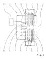
- Fig. 1 shows a schematic representation of a preferred embodiment of a trained as a transmission brake 1, electromagnetically actuated transmission shift element.
- gear brake 1 serves the defined braking of a shaft 2 of a motor vehicle transmission, wherein it is in particular the shaft 2, a so-called countershaft of the motor vehicle transmission.
- the electromagnetically actuated transmission brake 1 has a disk set 3, wherein the disk set 3 comprises a plurality of fins, namely first fins 4, which are assigned to be braked transmission shaft 2, and second fins 5, which are associated with a stator housing 6 of the transmission brake 1.
- the lamellae 4, 5 of the disk set 3 can be pressed with the help of an electromagnetic actuator adjustable more or less strongly with each other, so as to slow down the transmission brake 2 more or less.
- the electromagnetic actuator of the transmission brake 2 comprises at least one coil 7, which is integrated in a magnetic body 8, and an armature 9, wherein by energizing the coil 7, an electromagnetic field is established, which acts on the armature 9, wherein, depending on the size of the magnetic field, the disk set 3 of the transmission brake 1 is more or less strongly compressed.
- the transmission brake 1 In order to control or regulate the operation of the transmission brake 1, it comprises a speed sensor 10, by means of which the rotational speed of the transmission shaft 2 to be braked can be detected metrologically.
- the rotational speed sensor 10 which serves for the metrological detection of the rotational speed of the transmission shaft 2 to be braked, is integrated in the electromagnetic actuator, namely in accordance with the Fig. 1 shown, preferred embodiment in the magnetic body 8 of the actuator, which also receives the coil 7. Electrical connections of the coil 7 and the speed sensor 10, via which they can be connected to a control device 11, can be combined to form a unit.
- Fig. 1 are signal lines through which the coil 7 and the speed sensor 10 are connected to the control device 11, shown dotted.
- a sender wheel 12 cooperates, which in the embodiment of the Fig. 1 the braked transmission shaft 2 is assigned.
- the encoder wheel 12 moves in the embodiment of Fig. 1 past a surface of the rotational speed sensor 10 which extends parallel to the axis of rotation of the shaft 2 to be braked.
- the encoder wheel 12 is moved past a surface of the rotational speed sensor 10, which extends perpendicular to the axis of rotation of the gear shaft 2 to be braked. In this case, an axial detection of the rotational speed of the transmission shaft 2 to be braked would then take place.
- the encoder wheel 12 is not assigned to the transmission shaft 2, but rather the disk set 3, namely the first fins 4 of the disk set 3, which are associated with the braked transmission shaft 2.
- a sensor with a differential measuring method is preferably used, such as a differential Hall sensor.
- a magnetic bias of the speed sensor 10 can be impressed by the exciting field of the coil 7.
- the magnetic body 8 may be integrated in particular in the housing 6 or be firmly connected to this or be designed in one piece with the housing 6 in order to make the gear shift element particularly compact.
- two speed sensors are also required, which in turn in the sense of the invention in the electromagnetic actuator, by means of which the disk pack can be pressed, are integrated.
- the two speed sensors each cooperate with a transmitter wheel, which is assigned to the respective shaft or the respective disk pack.
Landscapes
- Engineering & Computer Science (AREA)
- General Engineering & Computer Science (AREA)
- Mechanical Engineering (AREA)
- Physics & Mathematics (AREA)
- Electromagnetism (AREA)
- Braking Arrangements (AREA)
- Dynamo-Electric Clutches, Dynamo-Electric Brakes (AREA)
- Control Of Transmission Device (AREA)
- Gear-Shifting Mechanisms (AREA)
Abstract
Description
- Die Erfindung betrifft ein elektromagnetisch betätigbares Getriebeschaltelement, insbesondere für eine elektromagnetisch betätigbare Getriebebremse.
- Aus der
DE 102 58 505 A1 ist eine elektromagnetisch betätigbare Getriebebremse eines Kraftfahrzeugs bekannt. Die dort offenbarte Getriebebremse verfügt über ein Lamellenpaket, wobei erste Lamellen des Lamellenpakets einer abzubremsenden Getriebewelle und zweite Lamellen des Lamellenpakets einem feststehenden Gehäuse zugeordnet sind. Neben dem Lamellenpaket verfügt die aus diesem Stand der Technik bekannte Getriebebremse weiterhin über einen elektromagnetischen Aktuator, um das Lamellenpaket mehr oder weniger stark zu verpressen und so ein definiertes Abbremsen der Getriebewelle zu realisieren. Der elektromagnetische Aktuator der Getriebebremse umfasst eine Ringspule und einen Ringanker, wobei durch Bestromen der Ringspule ein magnetisches Feld aufgebaut wird, das auf den Ringanker einwirkt. Ferner verfügt die aus diesem Stand der Technik bekannte Getriebebremse über einen Drehzahlsensor, der mit einem Geberrad zusammenwirkt, wobei mit Hilfe des Drehzahisensors sowie Geberrads die Drehzahl der abzubremsenden Getriebewelle erfasst werden kann, um so das Abbremsen derselben zu steuern bzw. zu regeln. Nach derDE 102 58 505 A1 kann das Geberrad der abzubremsenden Getriebewelle zugeordnet sein. Beim Drehzahlsensor handelt es sich um eine separate, eigenständige Baugruppe. - Hiervon ausgehend liegt der vorliegenden Erfindung das Problem zu Grunde, ein neuartiges elektromagnetisch betätigbares Getriebeschaltelement zu schaffen.
- Dieses Problem wird durch ein elektromagnetisch betätigbares Getriebeschaltelement gemäß Anspruch 1 gelöst. Erfindungsgemäß ist der oder jeder Drehzahlsensor in den elektromagnetischen Aktuator integriert.
- Gemäß der hier vorliegenden Erfindung ist der Drehzahlsensor in den elektromagnetischen Aktuator der elektromagnetisch betätigbaren Getriebebremse integriert. Vorzugsweise ist der Drehzahlsensor in einen Magnetkörper, der auch die oder jede Spule des elektromagnetischen Aktuators aufnimmt, integriert. Hierdurch ist es dann möglich elektrische Anschlüsse für die oder jede Spule sowie den Drehzahlsensor zusammenzufassen. Hierdurch ergibt sich ein einfacherer, kompakterer Aufbau und das Getriebeschaltelement ist mit geringerem Montageaufwand herstellbar.
- Bevorzugte Weiterbildungen der Erfindung ergeben sich aus den Unteransprüchen und der nachfolgenden Beschreibung. Ein Ausführungsbeispiel der Erfindung wird, ohne hierauf beschränkt zu sein, an Hand der Zeichnung näher erläutert. Dabei zeigt:
- Fig. 1
- eine stark schematisierte Darstellung eines erfindungsgemäßen, elektromagnetisch betätigbaren Getriebeschaltelements.
-
Fig. 1 zeigt eine schematisierte Darstellung eines bevorzugten Ausführungsbeispiels eines als Getriebebremse 1 ausgebildeten, elektromagnetisch betätigbaren Getriebeschaltelements. Die inFig. 1 gezeigte Getriebebremse 1 dient dem definierten Abbremsen einer Welle 2 eines Kraftfahrzeuggetriebes, wobei es sich bei der Welle 2 insbesondere um eine sogenannte Vorgelegewelle des Kraftfahrzeuggetriebes handelt. - Die elektromagnetisch betätigbare Getriebebremse 1 verfügt über ein Lamellenpaket 3, wobei das Lamellenpaket 3 mehrere Lamellen umfasst, nämlich erste Lamellen 4, die der abzubremsenden Getriebewelle 2 zugeordnet sind, und zweite Lamellen 5, die einem statorseitigen Gehäuse 6 der Getriebebremse 1 zugeordnet sind.
- Die Lamellen 4, 5 des Lamellenpakets 3 können mithilfe eines elektromagnetischen Aktuators einstellbar mehr oder weniger stark miteinander verpresst werden, um so die Getriebebremse 2 mehr oder weniger stark abzubremsen.
- Der elektromagnetische Aktuator der Getriebebremse 2 umfasst mindestens eine Spule 7, die in einem Magnetkörper 8 integriert ist, sowie einen Anker 9, wobei durch Bestromen der Spule 7 ein elektromagnetisches Feld aufgebaut wird, welches auf den Anker 9 einwirkt, wobei abhängig von der Größe des magnetischen Felds das Lamellenpaket 3 der Getriebebremse 1 mehr oder weniger stark zusammenpresst wird.
- Um den Betrieb der Getriebebremse 1 zu steuern bzw. zu regeln, umfasst dieselbe einen Drehzahlsensor 10, mithilfe dessen die Drehzahl der abzubremsenden Getriebewelle 2 messtechnisch erfasst werden kann.
- Im Sinne der hier vorliegenden Erfindung ist der Drehzahlsensor 10, der dem messtechnischen Erfassen der Drehzahl der abzubremsenden Getriebewelle 2 dient, in den elektromagnetischen Aktuator integriert, nämlich gemäß dem in
Fig. 1 gezeigten, bevorzugten Ausführungsbeispiel in den Magnetkörper 8 des Aktuators, der auch die Spule 7 aufnimmt. Elektrische Anschlüsse der Spule 7 sowie des Drehzahlsensors 10, über welchen dieselben an eine Regeleinrichtung 11 angeschlossen werden können, können so zu einer Einheit zusammengefasst werden. InFig. 1 sind Signalleitungen, über welche die Spule 7 sowie der Drehzahlsensor 10 mit der Regeleinrichtung 11 verbunden sind, punktiert dargestellt. - Mit dem Drehzahlsensor 10 wirkt ein Geberrad 12 zusammen, welches im Ausführungsbeispiel der
Fig. 1 der abzubremsenden Getriebewelle 2 zugeordnet ist. - Dabei bewegt sich das Geberrad 12 im Ausführungsbeispiel der
Fig. 1 an einer Fläche des Drehzahlsensors 10 vorbei, die sich parallel zu Rotationsachse der abzubremsenden Welle 2 erstreckt. InFig. 1 erfolgt demnach eine radiale Erfassung der Drehzahl der abzubremsenden Getriebewelle 2 mithilfe des Drehzahlsensors 10. - Im Unterschied zum gezeigten Ausführungsbeispiel ist es auch möglich, dass das Geberrad 12 an einer Fläche des Drehzahlsensors 10 vorbeibewegt wird, die sich senkrecht zur Drehachse der abzubremsenden Getriebewelle 2 erstreckt. In diesem Fall würde dann eine axiale Erfassung der Drehzahl der abzubremsenden Getriebewelle 2 erfolgen.
- Ebenfalls ist es im Unterschied zum gezeigten Ausführungsbeispiel der
Fig. 1 möglich, dass das Geberrad 12 nicht der Getriebewelle 2 zugeordnet ist, sondern vielmehr dem Lamellenpaket 3, nämlich den ersten Lamellen 4 des Lamellenpakets 3, die der abzubremsenden Getriebewelle 2 zugeordnet sind. - Als Drehzahlsensor 10 wird vorzugsweise ein Sensor mit einer differentiellen Messmethode verwendet, so zum Beispiel ein Differenz-Hall-Sensor. Eine magnetische Vorspannung des Drehzahlsensors 10 kann durch das Erregerfeld der Spule 7 eingeprägt werden.
- Der Magnetkörper 8 kann insbesondere in das Gehäuse 6 integriert sein oder mit diesem fest verbunden sein oder einstückig mit dem Gehäuse 6 ausgeführt sein, um das Getriebeschaltelement besonders kompakt auszuführen.
- Obwohl die hier vorliegenden Erfindung unter Bezugnahme auf
Fig. 1 am Beispiel einer Getriebebremse beschrieben wurde, kann die Erfindung auch bei einer Getriebekupplung zum Einsatz kommen. Bei einer Getriebekupplung müssen Drehzahlen von zwei rotierenden Wellen aneinander angepasst werden, weshalb bei einer Getriebekupplung erste Lamellen eines Lamellenpakets einer ersten, rotierenden Welle und zweite Lamellen desselben einer zweiten, rotierenden Welle zugeordnet sind. - Da in diesem Fall die Drehzahlen von zwei Wellen erfasst werden müssen, sind dann auch zwei Drehzahlsensoren erforderlich, die wiederum im Sinne der Erfindung in den elektromagnetischen Aktuator, mit Hilfe dessen das Lamellenpaket verpresst werden kann, integriert sind. Die beiden Drehzahlsensoren wirken jeweils mit einem Geberrad zusammen, welches der jeweiligen Welle oder dem jeweiligen Lamellenpaket zugeordnet ist.
-
- 1
- Getriebebremse
- 2
- Getriebewelle
- 3
- Lamellenpaket
- 4
- erste Lamellen
- 5
- zweite Lamellen
- 6
- Gehäuse
- 7
- Spule
- 8
- Magnetkörper
- 9
- Anker
- 10
- Drehzahlsensor
- 11
- Regeleinrichtung
- 12
- Geberrad
Claims (7)
- Elektromagnetisch betätigbares Getriebeschaltelement eines Kraftfahrzeugs, insbesondere elektromagnetisch betätigbare Getriebebremse (1), mit einem Lamellenpaket (3), mit einem elektromagnetischen Aktuator (7, 8, 9) zum einstellbaren mehr oder weniger starken Verpressen des Lamellenpakets (3), und mit mindestens einem Drehzahlsensor (10), dadurch gekennzeichnet, dass der oder jeder Drehzahlsensor (10) in den elektromagnetischen Aktuator integriert ist.
- Getriebeschaltelement nach Anspruch 1, dadurch gekennzeichnet, dass der elektromagnetische Aktuator einen Magnetkörper (8), der mindestens eine Spule (7) aufnimmt, und einen Anker (9) umfasst, und dass der oder jeder Drehzahlsensor (10) zusammen mit der oder jeder Spule (7) in den Magnetkörper (8) integriert ist.
- Getriebeschaltelement nach Anspruch 1 oder 2, dadurch gekennzeichnet, dass ein mit dem jeweiligen Drehzahlsensor (10) zusammenwirkendes Geberrad (12) einer abzubremsenden Welle (2) zugeordnet ist.
- Getriebeschaltelement nach Anspruch 1 oder 2, dadurch gekennzeichnet, dass ein mit dem jeweiligen Drehzahlsensor (10) zusammenwirkendes Geberrad (12) von Lamellen des Lamellenpakets (3), die einer abzubremsenden Welle (2) zugeordnet sind, gebildet ist.
- Getriebeschaltelement nach Anspruch 3 oder 4, dadurch gekennzeichnet, dass der jeweilige Drehzahlsensor (10) die Drehzahl der abzubremsenden Welle (2) axial zu der abzubremsenden Welle (2) detektiert.
- Getriebeschaltelement nach Anspruch 3 oder 4, dadurch gekennzeichnet, dass der jeweilige Drehzahlsensor (10) die Drehzahl der abzubremsenden Welle (2) radial zu der abzubremsenden Welle (2) detektiert.
- Getriebeschaltelement nach einem der Ansprüche 1 bis 6, dadurch gekennzeichnet, dass elektrische Anschlüsse für den oder jeden Drehzahlsensor (10) und die oder jede Spule (7) zusammengefasst sind.
Applications Claiming Priority (1)
| Application Number | Priority Date | Filing Date | Title |
|---|---|---|---|
| DE102008054668A DE102008054668A1 (de) | 2008-12-15 | 2008-12-15 | Getriebeschaltelement |
Publications (3)
| Publication Number | Publication Date |
|---|---|
| EP2196698A2 true EP2196698A2 (de) | 2010-06-16 |
| EP2196698A3 EP2196698A3 (de) | 2012-03-07 |
| EP2196698B1 EP2196698B1 (de) | 2014-04-30 |
Family
ID=41693477
Family Applications (1)
| Application Number | Title | Priority Date | Filing Date |
|---|---|---|---|
| EP09178446.2A Not-in-force EP2196698B1 (de) | 2008-12-15 | 2009-12-09 | Getriebeschaltelement |
Country Status (3)
| Country | Link |
|---|---|
| US (1) | US20100078288A1 (de) |
| EP (1) | EP2196698B1 (de) |
| DE (1) | DE102008054668A1 (de) |
Families Citing this family (4)
| Publication number | Priority date | Publication date | Assignee | Title |
|---|---|---|---|---|
| DE102010028075A1 (de) * | 2010-04-22 | 2011-10-27 | Zf Friedrichshafen Ag | Getriebebremse |
| DE102015214548A1 (de) * | 2015-07-30 | 2017-02-02 | Zf Friedrichshafen Ag | Optimieung von Schaltvorgängen |
| GB2566497B (en) * | 2017-09-15 | 2020-07-29 | Illinois Tool Works | Braking system for electromagnetic motors |
| EP3865725B1 (de) * | 2020-02-17 | 2024-03-27 | Ratier-Figeac SAS | Drehmomentbegrenzer |
Citations (1)
| Publication number | Priority date | Publication date | Assignee | Title |
|---|---|---|---|---|
| DE10258505A1 (de) | 2002-12-14 | 2004-07-01 | Zf Friedrichshafen Ag | Elektromagnetisch betätigbare Getriebebremse |
Family Cites Families (10)
| Publication number | Priority date | Publication date | Assignee | Title |
|---|---|---|---|---|
| US3582697A (en) * | 1970-01-28 | 1971-06-01 | Gen Electric | Combination motor-clutch apparatus |
| IT1161190B (it) * | 1983-04-27 | 1987-03-11 | Baruffaldi Frizioni Spa | Dispositivo di innesto a frizione elettromagnetica con disinnesto automatico particolarmente per prese di forza ausiliare di macchine agricole |
| FR2559222A1 (fr) * | 1984-02-07 | 1985-08-09 | Baruffaldi Frizioni Spa | Embrayage electromagnetique avec dispositif de mesure de la vitesse de rotation pour commandes d'appareils auxiliaires dans des vehicules |
| JPS62117571U (de) * | 1986-01-20 | 1987-07-25 | ||
| US5704444A (en) * | 1995-12-11 | 1998-01-06 | Borg-Warner Automotive, Inc. | Adaptive vehicle drive system for extreme operating conditioning |
| US5740895A (en) * | 1996-05-22 | 1998-04-21 | Warn Industries | Integrated wheel end system |
| JP2004308903A (ja) * | 2003-04-07 | 2004-11-04 | Luk Lamellen & Kupplungsbau Beteiligungs Kg | 電磁式の摩擦クラッチ |
| JP2007024257A (ja) * | 2005-07-20 | 2007-02-01 | Nippon Soken Inc | 電磁クラッチ付回転機 |
| JP2007064359A (ja) * | 2005-08-31 | 2007-03-15 | Ntn Corp | 回転伝達装置 |
| DE102005047952A1 (de) * | 2005-10-06 | 2007-04-12 | Zf Friedrichshafen Ag | Antrieb für ein Mobilfahrzeug |
-
2008
- 2008-12-15 DE DE102008054668A patent/DE102008054668A1/de not_active Withdrawn
-
2009
- 2009-12-07 US US12/632,077 patent/US20100078288A1/en not_active Abandoned
- 2009-12-09 EP EP09178446.2A patent/EP2196698B1/de not_active Not-in-force
Patent Citations (1)
| Publication number | Priority date | Publication date | Assignee | Title |
|---|---|---|---|---|
| DE10258505A1 (de) | 2002-12-14 | 2004-07-01 | Zf Friedrichshafen Ag | Elektromagnetisch betätigbare Getriebebremse |
Also Published As
| Publication number | Publication date |
|---|---|
| DE102008054668A1 (de) | 2010-06-17 |
| US20100078288A1 (en) | 2010-04-01 |
| EP2196698A3 (de) | 2012-03-07 |
| EP2196698B1 (de) | 2014-04-30 |
Similar Documents
| Publication | Publication Date | Title |
|---|---|---|
| EP2923103B1 (de) | Verfahren zur bestimmung und/oder ansteuerung einer position eines elektromotors | |
| DE102010006583B4 (de) | Drehmomentsensor mit Ausrichtungssystem | |
| EP1537341B1 (de) | Betätigungseinheit für eine elktromechanisch betätigbare scheibenbremse | |
| DE102013111891A1 (de) | Antriebsanordnung mit einer Kupplung und Verfahren zur Montage einer solchen Antriebsanordnung | |
| EP2196698B1 (de) | Getriebeschaltelement | |
| EP3330676B1 (de) | Positionsmesseinrichtung und verfahren zum betreiben einer positionsmesseinrichtung | |
| EP3781846B1 (de) | Verfahren zur bestimmung eines zustandes einer parksperre eines fahrzeuges | |
| DE102008047466A1 (de) | Magnetbaugruppe für eine Drehmoment- und/oder Drehwinkelsensoranordnung mit einem Magnetring und Herstellungsverfahren | |
| WO2011023285A1 (de) | Magnetbaugruppe für eine drehmoment- und/oder drehwinkelsensoranordnung mit einem magnetring und herstellungsverfahren | |
| WO2016041556A1 (de) | Sensorikeinheit zur bestimmung einer rotorlage eines elektromotors und ein elektromotor, vozugsweise für einen kupplungsaktor eines kupplungsbetätigungssystems eines kraftfahrzeuges | |
| DE102016211759B3 (de) | Verfahren zur Bestimmung einer Leckage in einem hydraulischen Kupplungssystem eines Hybridfahrzeuges | |
| DE10003250A1 (de) | Betätigungsvorrichtung | |
| DE19700936A1 (de) | Vorrichtung zur Betätigung eines betätigbaren Bauteiles | |
| DE102019211482A1 (de) | Sensoranordnung | |
| WO2017153027A1 (de) | Sensoreinrichtung für einen kupplungszentralausrücker, kupplungszentralausrücker sowie verfahren zum betreiben der sensoreinrichtung | |
| DE102019201952A1 (de) | Parksperre | |
| DE102006045732A1 (de) | Einrichtung und Verfahren zur Erfassung der Axialposition eines axial verschiebbaren und rotierenden Bauteils | |
| DE102012220073A1 (de) | Elektromechanisches Kupplungsbetätigungssystem und Verfahren zum Ansteuern einer Kupplung | |
| DE102017108307A1 (de) | Vorrichtung und Verfahren zur Drehmomentmessung in Lenksäulen und Antriebswellen | |
| DE102019203482A1 (de) | Stirnrad und dessen Herstellverfahren sowie bürstenloser Elektromotor | |
| WO2024231402A1 (de) | Stellantrieb mit elektromotor | |
| DE102009042828A1 (de) | Automatisiertes Kupplungssystem | |
| EP3714180A1 (de) | Verfahren zur steuerung eines aktuators für eine kupplung | |
| DE102024114290B3 (de) | Aktuator für ein elektromechanisches Fahrzeugbremssystem und elektromechanisches Fahrzeugbremssystem | |
| DE69020330T2 (de) | Antriebssystem mit Rotationsgeschwindigkeits-Sensor. |
Legal Events
| Date | Code | Title | Description |
|---|---|---|---|
| PUAI | Public reference made under article 153(3) epc to a published international application that has entered the european phase |
Free format text: ORIGINAL CODE: 0009012 |
|
| AK | Designated contracting states |
Kind code of ref document: A2 Designated state(s): AT BE BG CH CY CZ DE DK EE ES FI FR GB GR HR HU IE IS IT LI LT LU LV MC MK MT NL NO PL PT RO SE SI SK SM TR |
|
| AX | Request for extension of the european patent |
Extension state: AL BA RS |
|
| PUAL | Search report despatched |
Free format text: ORIGINAL CODE: 0009013 |
|
| AK | Designated contracting states |
Kind code of ref document: A3 Designated state(s): AT BE BG CH CY CZ DE DK EE ES FI FR GB GR HR HU IE IS IT LI LT LU LV MC MK MT NL NO PL PT RO SE SI SK SM TR |
|
| AX | Request for extension of the european patent |
Extension state: AL BA RS |
|
| RIC1 | Information provided on ipc code assigned before grant |
Ipc: F16D 65/14 20060101ALI20120127BHEP Ipc: F16D 55/00 20060101ALI20120127BHEP Ipc: F16H 3/12 20060101AFI20120127BHEP |
|
| 17P | Request for examination filed |
Effective date: 20120824 |
|
| 17Q | First examination report despatched |
Effective date: 20130530 |
|
| GRAP | Despatch of communication of intention to grant a patent |
Free format text: ORIGINAL CODE: EPIDOSNIGR1 |
|
| INTG | Intention to grant announced |
Effective date: 20131218 |
|
| GRAS | Grant fee paid |
Free format text: ORIGINAL CODE: EPIDOSNIGR3 |
|
| GRAA | (expected) grant |
Free format text: ORIGINAL CODE: 0009210 |
|
| AK | Designated contracting states |
Kind code of ref document: B1 Designated state(s): AT BE BG CH CY CZ DE DK EE ES FI FR GB GR HR HU IE IS IT LI LT LU LV MC MK MT NL NO PL PT RO SE SI SK SM TR |
|
| REG | Reference to a national code |
Ref country code: GB Ref legal event code: FG4D Free format text: NOT ENGLISH Ref country code: CH Ref legal event code: EP |
|
| REG | Reference to a national code |
Ref country code: AT Ref legal event code: REF Ref document number: 665357 Country of ref document: AT Kind code of ref document: T Effective date: 20140515 |
|
| REG | Reference to a national code |
Ref country code: IE Ref legal event code: FG4D Free format text: LANGUAGE OF EP DOCUMENT: GERMAN |
|
| REG | Reference to a national code |
Ref country code: DE Ref legal event code: R096 Ref document number: 502009009291 Country of ref document: DE Effective date: 20140612 |
|
| REG | Reference to a national code |
Ref country code: SE Ref legal event code: TRGR |
|
| REG | Reference to a national code |
Ref country code: LT Ref legal event code: MG4D |
|
| REG | Reference to a national code |
Ref country code: NL Ref legal event code: VDEP Effective date: 20140430 |
|
| PG25 | Lapsed in a contracting state [announced via postgrant information from national office to epo] |
Ref country code: NO Free format text: LAPSE BECAUSE OF FAILURE TO SUBMIT A TRANSLATION OF THE DESCRIPTION OR TO PAY THE FEE WITHIN THE PRESCRIBED TIME-LIMIT Effective date: 20140730 Ref country code: CY Free format text: LAPSE BECAUSE OF FAILURE TO SUBMIT A TRANSLATION OF THE DESCRIPTION OR TO PAY THE FEE WITHIN THE PRESCRIBED TIME-LIMIT Effective date: 20140430 Ref country code: BG Free format text: LAPSE BECAUSE OF FAILURE TO SUBMIT A TRANSLATION OF THE DESCRIPTION OR TO PAY THE FEE WITHIN THE PRESCRIBED TIME-LIMIT Effective date: 20140730 Ref country code: LT Free format text: LAPSE BECAUSE OF FAILURE TO SUBMIT A TRANSLATION OF THE DESCRIPTION OR TO PAY THE FEE WITHIN THE PRESCRIBED TIME-LIMIT Effective date: 20140430 Ref country code: GR Free format text: LAPSE BECAUSE OF FAILURE TO SUBMIT A TRANSLATION OF THE DESCRIPTION OR TO PAY THE FEE WITHIN THE PRESCRIBED TIME-LIMIT Effective date: 20140731 Ref country code: IS Free format text: LAPSE BECAUSE OF FAILURE TO SUBMIT A TRANSLATION OF THE DESCRIPTION OR TO PAY THE FEE WITHIN THE PRESCRIBED TIME-LIMIT Effective date: 20140830 Ref country code: NL Free format text: LAPSE BECAUSE OF FAILURE TO SUBMIT A TRANSLATION OF THE DESCRIPTION OR TO PAY THE FEE WITHIN THE PRESCRIBED TIME-LIMIT Effective date: 20140430 Ref country code: FI Free format text: LAPSE BECAUSE OF FAILURE TO SUBMIT A TRANSLATION OF THE DESCRIPTION OR TO PAY THE FEE WITHIN THE PRESCRIBED TIME-LIMIT Effective date: 20140430 |
|
| PG25 | Lapsed in a contracting state [announced via postgrant information from national office to epo] |
Ref country code: ES Free format text: LAPSE BECAUSE OF FAILURE TO SUBMIT A TRANSLATION OF THE DESCRIPTION OR TO PAY THE FEE WITHIN THE PRESCRIBED TIME-LIMIT Effective date: 20140430 Ref country code: HR Free format text: LAPSE BECAUSE OF FAILURE TO SUBMIT A TRANSLATION OF THE DESCRIPTION OR TO PAY THE FEE WITHIN THE PRESCRIBED TIME-LIMIT Effective date: 20140430 Ref country code: LV Free format text: LAPSE BECAUSE OF FAILURE TO SUBMIT A TRANSLATION OF THE DESCRIPTION OR TO PAY THE FEE WITHIN THE PRESCRIBED TIME-LIMIT Effective date: 20140430 Ref country code: PL Free format text: LAPSE BECAUSE OF FAILURE TO SUBMIT A TRANSLATION OF THE DESCRIPTION OR TO PAY THE FEE WITHIN THE PRESCRIBED TIME-LIMIT Effective date: 20140430 |
|
| PG25 | Lapsed in a contracting state [announced via postgrant information from national office to epo] |
Ref country code: PT Free format text: LAPSE BECAUSE OF FAILURE TO SUBMIT A TRANSLATION OF THE DESCRIPTION OR TO PAY THE FEE WITHIN THE PRESCRIBED TIME-LIMIT Effective date: 20140901 |
|
| PG25 | Lapsed in a contracting state [announced via postgrant information from national office to epo] |
Ref country code: SK Free format text: LAPSE BECAUSE OF FAILURE TO SUBMIT A TRANSLATION OF THE DESCRIPTION OR TO PAY THE FEE WITHIN THE PRESCRIBED TIME-LIMIT Effective date: 20140430 Ref country code: CZ Free format text: LAPSE BECAUSE OF FAILURE TO SUBMIT A TRANSLATION OF THE DESCRIPTION OR TO PAY THE FEE WITHIN THE PRESCRIBED TIME-LIMIT Effective date: 20140430 Ref country code: RO Free format text: LAPSE BECAUSE OF FAILURE TO SUBMIT A TRANSLATION OF THE DESCRIPTION OR TO PAY THE FEE WITHIN THE PRESCRIBED TIME-LIMIT Effective date: 20140430 Ref country code: DK Free format text: LAPSE BECAUSE OF FAILURE TO SUBMIT A TRANSLATION OF THE DESCRIPTION OR TO PAY THE FEE WITHIN THE PRESCRIBED TIME-LIMIT Effective date: 20140430 Ref country code: EE Free format text: LAPSE BECAUSE OF FAILURE TO SUBMIT A TRANSLATION OF THE DESCRIPTION OR TO PAY THE FEE WITHIN THE PRESCRIBED TIME-LIMIT Effective date: 20140430 |
|
| PGFP | Annual fee paid to national office [announced via postgrant information from national office to epo] |
Ref country code: SE Payment date: 20141211 Year of fee payment: 6 |
|
| REG | Reference to a national code |
Ref country code: DE Ref legal event code: R097 Ref document number: 502009009291 Country of ref document: DE |
|
| PGFP | Annual fee paid to national office [announced via postgrant information from national office to epo] |
Ref country code: FR Payment date: 20141208 Year of fee payment: 6 |
|
| PLBE | No opposition filed within time limit |
Free format text: ORIGINAL CODE: 0009261 |
|
| STAA | Information on the status of an ep patent application or granted ep patent |
Free format text: STATUS: NO OPPOSITION FILED WITHIN TIME LIMIT |
|
| PG25 | Lapsed in a contracting state [announced via postgrant information from national office to epo] |
Ref country code: IT Free format text: LAPSE BECAUSE OF FAILURE TO SUBMIT A TRANSLATION OF THE DESCRIPTION OR TO PAY THE FEE WITHIN THE PRESCRIBED TIME-LIMIT Effective date: 20140430 |
|
| 26N | No opposition filed |
Effective date: 20150202 |
|
| REG | Reference to a national code |
Ref country code: DE Ref legal event code: R097 Ref document number: 502009009291 Country of ref document: DE Effective date: 20150202 |
|
| PG25 | Lapsed in a contracting state [announced via postgrant information from national office to epo] |
Ref country code: BE Free format text: LAPSE BECAUSE OF NON-PAYMENT OF DUE FEES Effective date: 20141231 |
|
| PG25 | Lapsed in a contracting state [announced via postgrant information from national office to epo] |
Ref country code: SI Free format text: LAPSE BECAUSE OF FAILURE TO SUBMIT A TRANSLATION OF THE DESCRIPTION OR TO PAY THE FEE WITHIN THE PRESCRIBED TIME-LIMIT Effective date: 20140430 Ref country code: LU Free format text: LAPSE BECAUSE OF FAILURE TO SUBMIT A TRANSLATION OF THE DESCRIPTION OR TO PAY THE FEE WITHIN THE PRESCRIBED TIME-LIMIT Effective date: 20141209 |
|
| REG | Reference to a national code |
Ref country code: CH Ref legal event code: PL |
|
| GBPC | Gb: european patent ceased through non-payment of renewal fee |
Effective date: 20141209 |
|
| REG | Reference to a national code |
Ref country code: IE Ref legal event code: MM4A |
|
| PG25 | Lapsed in a contracting state [announced via postgrant information from national office to epo] |
Ref country code: GB Free format text: LAPSE BECAUSE OF NON-PAYMENT OF DUE FEES Effective date: 20141209 Ref country code: LI Free format text: LAPSE BECAUSE OF NON-PAYMENT OF DUE FEES Effective date: 20141231 Ref country code: CH Free format text: LAPSE BECAUSE OF NON-PAYMENT OF DUE FEES Effective date: 20141231 Ref country code: IE Free format text: LAPSE BECAUSE OF NON-PAYMENT OF DUE FEES Effective date: 20141209 |
|
| REG | Reference to a national code |
Ref country code: AT Ref legal event code: MM01 Ref document number: 665357 Country of ref document: AT Kind code of ref document: T Effective date: 20141209 |
|
| PG25 | Lapsed in a contracting state [announced via postgrant information from national office to epo] |
Ref country code: SM Free format text: LAPSE BECAUSE OF FAILURE TO SUBMIT A TRANSLATION OF THE DESCRIPTION OR TO PAY THE FEE WITHIN THE PRESCRIBED TIME-LIMIT Effective date: 20140430 |
|
| PG25 | Lapsed in a contracting state [announced via postgrant information from national office to epo] |
Ref country code: AT Free format text: LAPSE BECAUSE OF NON-PAYMENT OF DUE FEES Effective date: 20141209 Ref country code: MC Free format text: LAPSE BECAUSE OF FAILURE TO SUBMIT A TRANSLATION OF THE DESCRIPTION OR TO PAY THE FEE WITHIN THE PRESCRIBED TIME-LIMIT Effective date: 20140430 |
|
| PG25 | Lapsed in a contracting state [announced via postgrant information from national office to epo] |
Ref country code: HU Free format text: LAPSE BECAUSE OF FAILURE TO SUBMIT A TRANSLATION OF THE DESCRIPTION OR TO PAY THE FEE WITHIN THE PRESCRIBED TIME-LIMIT; INVALID AB INITIO Effective date: 20091209 Ref country code: TR Free format text: LAPSE BECAUSE OF FAILURE TO SUBMIT A TRANSLATION OF THE DESCRIPTION OR TO PAY THE FEE WITHIN THE PRESCRIBED TIME-LIMIT Effective date: 20140430 Ref country code: MT Free format text: LAPSE BECAUSE OF FAILURE TO SUBMIT A TRANSLATION OF THE DESCRIPTION OR TO PAY THE FEE WITHIN THE PRESCRIBED TIME-LIMIT Effective date: 20140430 |
|
| REG | Reference to a national code |
Ref country code: SE Ref legal event code: EUG |
|
| PG25 | Lapsed in a contracting state [announced via postgrant information from national office to epo] |
Ref country code: SE Free format text: LAPSE BECAUSE OF NON-PAYMENT OF DUE FEES Effective date: 20151210 |
|
| REG | Reference to a national code |
Ref country code: FR Ref legal event code: ST Effective date: 20160831 |
|
| PG25 | Lapsed in a contracting state [announced via postgrant information from national office to epo] |
Ref country code: FR Free format text: LAPSE BECAUSE OF NON-PAYMENT OF DUE FEES Effective date: 20151231 |
|
| PGFP | Annual fee paid to national office [announced via postgrant information from national office to epo] |
Ref country code: DE Payment date: 20171206 Year of fee payment: 9 |
|
| PG25 | Lapsed in a contracting state [announced via postgrant information from national office to epo] |
Ref country code: MK Free format text: LAPSE BECAUSE OF FAILURE TO SUBMIT A TRANSLATION OF THE DESCRIPTION OR TO PAY THE FEE WITHIN THE PRESCRIBED TIME-LIMIT Effective date: 20140430 |
|
| REG | Reference to a national code |
Ref country code: DE Ref legal event code: R119 Ref document number: 502009009291 Country of ref document: DE |
|
| PG25 | Lapsed in a contracting state [announced via postgrant information from national office to epo] |
Ref country code: DE Free format text: LAPSE BECAUSE OF NON-PAYMENT OF DUE FEES Effective date: 20190702 |