EP2196624B1 - Laufschaufel für eine Gasturbine - Google Patents
Laufschaufel für eine Gasturbine Download PDFInfo
- Publication number
- EP2196624B1 EP2196624B1 EP09178286.2A EP09178286A EP2196624B1 EP 2196624 B1 EP2196624 B1 EP 2196624B1 EP 09178286 A EP09178286 A EP 09178286A EP 2196624 B1 EP2196624 B1 EP 2196624B1
- Authority
- EP
- European Patent Office
- Prior art keywords
- blade
- rotor
- rotor blade
- tension rod
- longitudinal direction
- Prior art date
- Legal status (The legal status is an assumption and is not a legal conclusion. Google has not performed a legal analysis and makes no representation as to the accuracy of the status listed.)
- Active
Links
- 239000000463 material Substances 0.000 claims description 17
- 125000006850 spacer group Chemical group 0.000 claims description 7
- 238000004519 manufacturing process Methods 0.000 description 7
- 238000005266 casting Methods 0.000 description 4
- 239000000919 ceramic Substances 0.000 description 2
- 239000002131 composite material Substances 0.000 description 1
- 230000007797 corrosion Effects 0.000 description 1
- 238000005260 corrosion Methods 0.000 description 1
- 230000012447 hatching Effects 0.000 description 1
- 239000007791 liquid phase Substances 0.000 description 1
- 239000007769 metal material Substances 0.000 description 1
- 238000005457 optimization Methods 0.000 description 1
- 238000000926 separation method Methods 0.000 description 1
- 239000013585 weight reducing agent Substances 0.000 description 1
Images
Classifications
-
- F—MECHANICAL ENGINEERING; LIGHTING; HEATING; WEAPONS; BLASTING
- F01—MACHINES OR ENGINES IN GENERAL; ENGINE PLANTS IN GENERAL; STEAM ENGINES
- F01D—NON-POSITIVE DISPLACEMENT MACHINES OR ENGINES, e.g. STEAM TURBINES
- F01D5/00—Blades; Blade-carrying members; Heating, heat-insulating, cooling or antivibration means on the blades or the members
- F01D5/12—Blades
- F01D5/14—Form or construction
- F01D5/147—Construction, i.e. structural features, e.g. of weight-saving hollow blades
-
- F—MECHANICAL ENGINEERING; LIGHTING; HEATING; WEAPONS; BLASTING
- F05—INDEXING SCHEMES RELATING TO ENGINES OR PUMPS IN VARIOUS SUBCLASSES OF CLASSES F01-F04
- F05D—INDEXING SCHEME FOR ASPECTS RELATING TO NON-POSITIVE-DISPLACEMENT MACHINES OR ENGINES, GAS-TURBINES OR JET-PROPULSION PLANTS
- F05D2240/00—Components
- F05D2240/20—Rotors
- F05D2240/30—Characteristics of rotor blades, i.e. of any element transforming dynamic fluid energy to or from rotational energy and being attached to a rotor
-
- F—MECHANICAL ENGINEERING; LIGHTING; HEATING; WEAPONS; BLASTING
- F05—INDEXING SCHEMES RELATING TO ENGINES OR PUMPS IN VARIOUS SUBCLASSES OF CLASSES F01-F04
- F05D—INDEXING SCHEME FOR ASPECTS RELATING TO NON-POSITIVE-DISPLACEMENT MACHINES OR ENGINES, GAS-TURBINES OR JET-PROPULSION PLANTS
- F05D2260/00—Function
- F05D2260/30—Retaining components in desired mutual position
- F05D2260/36—Retaining components in desired mutual position by a form fit connection, e.g. by interlocking
Definitions
- the present invention relates to the field of gas turbine technology. It relates to a blade for a gas turbine according to the preamble of claim 1.
- Uncooled hollow turbine blades are usually cast from a material. But it is also known ( US B1-6,331,217 ), large rotor blades of a gas turbine from several separately cast blade parts by liquid phase bonding together. Here, either the blade is divided in the blade longitudinal direction (Fig. 3 of the US B1-6,331,217 ) or the entire airfoil is separated from the platform and the blade root manufactured (Fig. 6 of the US B1-6,331,217 ). This leads, especially in the case of large blades, to the fact that, despite the subdivision, large castings for the airfoil have to be produced and positively connected to one another.
- a blade is known in which the profile sheet height according to several sections (1 a and 1 b) is composed.
- the blade core (2) which extends in one piece from the blade root to the blade tip, is not subdivided.
- the center of the document D1 is thus the subdivision of the blade from inside to outside into the central blade core and the blade core enveloping the blade core.
- EP 1 905 954 A is the pitch of the blade in the area of the blade root ( Fig. 1 . 2 ).
- the entire airfoil is in one piece, whereby the production is not significantly facilitated.
- the blade is composed of several individual parts, the material of each of which is adapted to the intended use of the item in question, and that each of the items is significantly smaller in dimensions than the composite blade, that the items of the blade a lower Blade part and an adjoining in the blade longitudinal direction of the upper blade member, wherein the blade is divided in blade longitudinal direction on the lower and upper blade portion, and that the lower blade portion includes the platform and at least a portion of the blade root.
- the invention thus pursues the idea to build a gas turbine blade from several, relatively small items of different materials whose material properties can be adapted to the respective local loads. Due to the possible variation of the materials, a clear optimization potential with respect to the own weight, the manufacturability and the manufacturing costs of the blade is revealed.
- the idea of the invention is therefore to build the gas turbine blade from several individual parts in order to be able to exploit targeted material properties and to avoid any size-related manufacturing problems.
- a clear separation of functions between the different parts is to be achieved. This is associated with the known and used materials with a relatively high density. This relationship can be represented by the so-called specific density. This is the relation between material strength values and their density. By such a split airfoil, the dimension of the individual castings can be significantly reduced.
- An embodiment of the blade according to the invention is characterized in that the individual parts are at least partially connected by positive locking.
- Another embodiment of the blade according to the invention is characterized in that the upper blade part includes the blade tip.
- a further embodiment is characterized in that, for receiving the centrifugal forces acting on the upper blade part, a tie rod extending in the longitudinal direction of the blade is arranged in the blade longitudinal direction, that the tie rod engages with its upper end with the lower end of the upper blade part, and that Tie rod with its lower end introduces the tensile forces in the blade root.
- the tie rod has a foot section on which forms part of the blade root and with which the tie rod engages behind the lower blade part.
- an inwardly angled first angle element is arranged on the upper blade part, wherein the tie rod engages with the upper blade part in that it engages behind the first angle element with a second angle element.
- the tie rod can also consist of several in the blade longitudinal direction arranged in parallel partial anchors, wherein the partial anchors are spaced transversely to the blade longitudinal direction from each other, and wherein the distance of the partial anchors is determined by subsequently usable spacers.
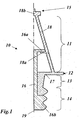
- Fig. 1 shows a longitudinal section through a (built) blade according to an embodiment of the invention.
- the blade 10 of the Fig. 1 consists of three separate components, namely an upper blade portion 18, a lower blade portion 17 and a tie rod 16.
- the blade 10 has an aerodynamically effective airfoil 11 extending in the blade longitudinal direction between a blade tip 15 and a platform 12.
- the airfoil 11 is divided longitudinally onto the upper blade part 18 and onto the lower blade part 17.
- a shroud segment 18b is formed at the upper end of the upper blade part 18.
- an inwardly projecting first angle member 18a is formed, behind which engages the inner tie rod 16 with a mounted at its upper end second angle member 16a and thus holds the upper blade member 18 against the centrifugal forces occurring.
- the upper blade part 18 is thus loaded only on train.
- the lower blade part 17 comprises the lower part of the blade 11, the platform 12 a shaft 13 and a part of a blade root 14, which in the shown example, a fir tree-like edge profile (with 3 teeth) has.
- Another part of the blade root 14 is formed by a foot section 16b, with which the tie rod 16 engages behind the lower blade part 17.
- the upper blade portion 18 and the lower blade portion 17 must have a significantly higher temperature and creep resistance than the inner tie rod 16.
- the materials used for the parts 17, 18 on the one hand and the part 16 on the other hand can be correspondingly different. Within the blade height, however, the temperatures vary so strongly that the use of differently adapted materials is also recommended for the two blade parts 17 and 18.
- Even the tie rod 16 can-as in Fig. 1 indicated by the different hatching - if necessary in the longitudinal direction consist of different materials. But it can also be made of a material throughout.
- the assembly of an inventive blade can be done in different ways: If the tie rod 16 is not divided in the longitudinal direction in a median plane 19, he can, for example, 90 ° twisted introduced from below into the blade interior and then by a rotation of 90 ° back into engagement with the angle member 18a at the lower end of the upper blade portion 18 are brought.
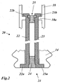
- a tie rod 21 divided in the longitudinal direction which comprises two partial anchors 22 and 23 which are mirror-symmetrical to one another and which are spaced apart transversely in the installed state and are kept at a distance by corresponding spacers 24 and 25.
- the two partial anchors 22, 23 are first inserted without spacers 24, 25 and without transverse spacing in the blade interior until the partial anchors 22, 23 can engage with their upper angle elements 22b, 23b behind the angle elements 18a of the airfoil.
- the upper (round) spacer 25 from below between the two partial anchors pushed up until he was in Fig. 2 has reached the position shown and the two partial anchors 22, 23 fixed in the hooked position.
- the lower spacer 24 is inserted between the partial anchors 22, 23 so that they are supported with lower angle elements from the inside on a shoulder on the blade root 14.
Description
- Die vorliegende Erfindung bezieht sich auf das Gebiet der Gasturbinentechnik. Sie betrifft eine Laufschaufel für eine Gasturbine gemäss dem Oberbegriff des Anspruchs 1.
- Ungekühlte, hohle Turbinenlaufschaufeln werden üblicherweise aus einem Material gegossen. Es ist aber auch bekannt (
US-B1-6,331,217 ), grosse Laufschaufeln einer Gasturbine aus mehreren separat gegossenen Schaufelteilen durch Liquid Phase Bonding zusammenzufügen. Hierbei wird entweder das Schaufelblatt in Schaufellängsrichtung geteilt (Fig. 3 derUS-B1-6,331,217 ) oder das gesamte Schaufelblatt wird getrennt von der Plattform und dem Schaufelfuss hergestellt (Fig. 6 derUS-B1-6,331,217 ). Dies führt gerade bei grossen Schaufeln dazu, dass trotz der Unterteilung grosse Gussstücke für das Schaufelblatt hergestellt und formschlüssig miteinander verbunden werden müssen. - Dasselbe gilt auch für die in der
US-A1-2006/0120869 beschriebene Laufschaufel, die im Inneren der Schaufel einen in Längsrichtung durchgehenden Holm (12) aufweist, der im Bereich des Schaufelblattes aussen von einer aerodynamisch wirksamen Hülle (48) umschlossen ist. Eine ähnliches Konzept, bei dem die äussere Hülle mit einer Druckspannung vorgespannt wird, ist aus derUS-A-4,473,336 bekannt. Schliesslich ist es aus derUS-A-4,563,128 eine vergleichbare Konfiguration bekannt, bei der die äussere Hülle des Schaufelblattes aus einer Keramik besteht. - Aus der Druckschrift
NL 7 905 608 A DE 28 34 843 ) ist eine Schaufel bekannt, bei der das Profilblatt seiner Höhe nach aus mehreren Abschnitten (1 a und 1 b) zusammengesetzt ist. Nicht unterteilt ist dagegen der Schaufelkern (2), der sich vom Schaufelfuss bis zur Schaufelspitze einstückig erstreckt. Im Zentrum der Druckschrift D1 steht somit die Unterteilung der Schaufel von innen nach außen in den zentralen Schaufelkern und das den Schaufelkern umhüllende Schaufelblatt. - In der Druckschrift
US 4,786,234 wird (Fig. 5) zwar eine Unterteilung der Schaufel in ein oberes Teil (112) und ein unteres Teil (102) vorgenommen. Der Kern (100) bleibt jedoch durchgehend. Das untere Schaufelteil (102) ist nur am oberen Ende gegen die Fliehkräfte abgestützt. - In der Druckschrift
EP 1 905 954 A ist die Teilung der Schaufel im Bereich des Schaufelfusses (Fig. 1 ,2 ). Das gesamte Schaufelblatt ist einstückig, wodurch die Herstellung nicht wesentlich erleichtert wird. - In der Druckschrift
FR 2 463 849 Fig. 1 ). - Mit der Steigerung der Wirkungsgrade und Effizienz von modernen Gasturbinenanlagen werden die Dimensionen der einzelnen Komponenten und somit der Laufschaufeln ebenfalls vergrössert. Dadurch können unter anderem erhebliche gewichtsbedingte Probleme im Einsatz sowie fertigungstechnische Schwierigkeiten beim Giessen grosser Bauteile auftreten.
- Es ist daher Aufgabe der Erfindung, eine Gasturbinen-Laufschaufel zu schaffen, die hinsichtlich ihres Gewichts optimiert ist, ohne dabei an Effizienz einzubüssen.
- Die Aufgabe wird durch die Gesamtheit der Merkmale des Anspruchs 1 gelöst. Wesentlich für die Erfindung ist, dass die Schaufel aus mehreren Einzelteilen zusammengesetzt ist, deren Material jeweils dem Einsatzzweck des betreffenden Einzelteils angepasst ist, und dass jedes der Einzelteile von den Abmessungen her deutlich kleiner ist als die zusammengesetzte Laufschaufel, dass die Einzelteile der Laufschaufel ein unteres Schaufelteil und ein in Schaufellängsrichtung daran anschliessendes oberes Schaufelteil umfassen, wobei das Schaufelblatt in Schaufellängsrichtung auf das untere und obere Schaufelteil aufgeteilt ist, und dass das untere Schaufelteil die Plattform und zumindest einen Teil des Schaufelfusses mit umfasst.
- Die Erfindung verfolgt damit den Gedanken, eine Gasturbinen-Laufschaufel aus mehreren, vergleichsweise kleinen Einzelteilen verschiedener Materialien zu bauen, deren Materialeigenschaften an die jeweiligen lokalen Belastungen angepasst werden können. Auf Grund der so möglichen Variation der Materialien offenbart sich ein deutliches Optimierungspotential hinsichtlich des Eigengewichtes, der Herstellbarkeit und Herstellkosten der Laufschaufel.
- Die Erfindungsidee ist es also, die Gasturbinen-Laufschaufel aus mehreren Einzelteilen zu bauen, um somit gezielt Materialeigenschaften ausnutzen zu können und eventuelle grössenbedingte Herstellungsprobleme zu vermeiden. Eine klare Funktionstrennung der verschiedenen Teile soll erreicht werden. Dies geht mit den bekannten und genutzten Materialien mit einer relativ hohen Dichte einher. Dieser Zusammenhang ist mit der so genannten spezifischen Dichte darstellbar. Dies ist die Relation zwischen Materialfestigkeitswerten und deren Dichte. Durch ein solches geteiltes Schaufelblatt kann die Dimension der einzelnen Gussteile massgeblich reduziert werden.
- Dafür können auch Materialien verwendet werden, die eine geringere Dichte aufweisen. Insgesamt können kleinere Bauteile fertigungstechnisch effizienter hergestellt werden, als ein grosses Bauteil. Durch den Zusammenbau der Schaufel aus materialoptimierten Einzelteilen können folgende Vorteile erzielt werden:
- Kostenreduktion
- o Flexiblere Materialauswahl durch Fertigung mehrerer Einzelteile
- o Effizientere Fertigung (höhere Ausbeute) durch Grössenreduktion der Gussteile
- Optimierte Materialauswahl
- o Korrosionsbeständige Hülle (u.U. aus Blechmaterial)
- o Zuganker mit hoher spezifischer Festigkeit
- Gewichtsreduktion durch teilweise Verwendung von Werkstoffen mit niedriger Dichte
- Der Zuganker kann tiefer in den Rotorkörper greifen (> 3 Zacken am Schaufelfuss oder "long shank")
- Eine Ausgestaltung der Laufschaufel nach der Erfindung ist dadurch gekennzeichnet, dass die Einzelteile zumindest teilweise durch Formschluss miteinander verbunden sind.
- Eine andere Ausgestaltung der erfindungsgemässen Schaufel zeichnet sich dadurch aus, dass das obere Schaufelteil die Schaufelspitze mit umfasst.
- Eine weitere Ausgestaltung ist dadurch gekennzeichnet, dass zum Aufnehmen der am oberen Schaufelteil angreifenden Fliehkräfte im Inneren der Laufschaufel ein sich in Schaufellängsrichtung erstreckender Zuganker angeordnet ist, dass der Zuganker mit seinem oberen Ende mit dem unteren Ende des oberen Schaufelteils in Eingriff steht, und dass der Zuganker mit seinem unteren Ende die Zugkräfte in den Schaufelfuss einleitet. Insbesondere weist der Zuganker einen Fussabschnitt
auf, der einen Teil des Schaufelfusses bildet und mit dem der Zuganker das untere Schaufelteil hintergreift. - Gemäss einer anderen Ausgestaltung ist am oberen Schaufelteil ein nach innen abgewinkeltes erstes Winkelelement angeordnet, wobei der Zuganker mit dem oberen Schaufelteil dadurch in Eingriff steht, dass er mit einem zweiten Winkelelement hinter das erste Winkelelement greift.
- Der Zuganker kann aber auch aus mehreren in Schaufellängsrichtung parallel angeordneten Teilankern bestehen, wobei die Teilanker quer zur Schaufellängsrichtung voneinander beabstandet sind, und wobei der Abstand der Teilanker durch nachträglich einsetzbare Abstandshalter festgelegt wird.
- Die Erfindung soll nachfolgend anhand von Ausführungsbeispielen im Zusammenhang mit der Zeichnung näher erläutert werden. Es zeigen
- Fig. 1
- einen Längschnitt durch eine Laufschaufel gemäss einem Ausführungsbeispiel der Erfindung; und
- Fig. 2
- den Längsschnitt durch eine zu
Fig. 1 alternative Zugankeranordnung. -
Fig. 1 zeigt einen Längsschnitt durch eine (gebaute) Laufschaufel gemäss einem Ausführungsbeispiel der Erfindung. Die Laufschaufel 10 derFig. 1 besteht aus drei einzelnen Komponenten, nämlich einem oberen Schaufelteil 18, einem unteren Schaufelteil 17 und einem Zuganker 16. Die Laufschaufel 10 hat ein aerodynamisch wirksames Schaufelblatt 11, das sich in Schaufellängsrichtung zwischen einer Schaufelspitze 15 und einer Plattform 12 erstreckt. Das Schaufelblatt 11 ist in Längsrichtung aufgeteilt auf das obere Schaufelteil 18 und auf das untere Schaufelteil 17. Am oberen Ende des oberen Schaufelteils 18 ist ein Deckbandsegment 18b ausgebildet. Am unteren Ende des oberen Schaufelteils 18 ist ein nach innen vorspringendes erstes Winkelelement 18a angeformt, hinter das der innen liegende Zuganker 16 mit einem an seinem oberen Ende angebrachten zweiten Winkelelement 16a greift und damit das obere Schaufelteil 18 gegen die auftretenden Fliehkräfte hält. Das obere Schaufelteil 18 ist so nur auf Zug belastet. - Das untere Schaufelteil 17 umfasst den unteren Teil des Schaufelblattes 11, die Plattform 12 einen Schaft 13 und einen Teil eines Schaufelfusses 14, der im gezeigten Beispiel ein tannenbaumartiges Randprofil (mit 3 Zacken) aufweist. Ein anderer Teil des Schaufelfusses 14 wird von einem Fussabschnitt 16b gebildet, mit dem der Zuganker 16 das untere Schaufelteil 17 hintergreift.
- In der in
Fig. 1 gezeigten Konfiguration müssen das obere Schaufelteil 18 und das untere Schaufelteil 17 eine deutlich höhere Temperatur- und Kriechbeständigkeit aufweisen als der innen liegende Zuganker 16. Entsprechend unterschiedlich können die verwendeten Materialien der Teile 17, 18 einerseits und des Teils 16 andererseits sein. Innerhalb der Schaufelhöhe variieren die Temperaturen jedoch so stark, dass sich auch für die beiden Schaufelteile 17 und 18 der Einsatz unterschiedlich angepasster Werkstoffe empfiehlt. Selbst der Zuganker 16 kann-wie inFig. 1 durch die unterschiedliche Schraffur angedeutet ist - bei Bedarf in der Längsrichtung aus unterschiedlichen Werkstoffen bestehen. Er kann aber auch durchgehend aus einem Werkstoff gefertigt sein. - Der Zusammenbau einer erfindungsgemässen Laufschaufel kann auf unterschiedliche Weise erfolgen: Wenn der Zuganker 16 in Längsrichtung nicht in einer Mittelebene 19 geteilt ist, kann er beispielsweise um 90 ° verdreht von unten in das Schaufelinnere eingeführt und dann durch eine Drehung um 90° zurück in Eingriff mit dem Winkelelement 18a am unteren Ende des oberen Schaufelteils 18 gebracht werden.
- Es ist aber auch denkbar, gemäss
Fig. 2 bei einer Laufschaufel 20 einen in Längsrichtung geteilten Zuganker 21 vorzusehen, der zwei spiegelsymmetrisch zueinander ausgebildete Teilanker 22 und 23 umfasst, die im eingebauten Zustand in Querrichtung voneinander beabstandet sind und durch entsprechende Abstandshalter 24 und 25 auf Abstand gehalten werden. Beim Zusammenbau der Laufschaufel 20 werden die beiden Teilanker 22, 23 zunächst ohne Abstandshalter 24, 25 und ohne Querabstand in das Schaufelinnere eingeschoben, bis die Teilanker 22, 23 mit ihren oberen Winkelelementen 22b, 23b hinter die Winkelelemente 18a des Schaufelblattes greifen können. Dann wird der obere (runde) Abstandshalter 25 von unten zwischen den beiden Teilankern nach oben geschoben, bis er die inFig. 2 gezeigte Position erreicht hat und die beiden Teilanker 22, 23 in der eingehakten Stellung fixiert. Schliesslich wird am unteren Ende der untere Abstandshalter 24 zwischen die Teilanker 22, 23 eingeführt, so dass diese sich mit unteren Winkelelementen von innen an einem Absatz am Schaufelfuss 14 abstützen. -
- 10,20
- Laufschaufel (Gasturbine)
- 11
- Schaufelblatt
- 12
- Plattform
- 13
- Schaft
- 14
- Schaufelfuss
- 15
- Schaufelspitze
- 16,21
- Zuganker
- 16a
- Winkelelement
- 16b
- Fussabschnitt
- 17
- unterer Schaufelteil
- 18
- oberer Schaufelteil
- 18a
- Winkelelement
- 18b
- Deckbandsegment
- 19
- Mittelebene
- 22,23
- Teilanker
- 22a,23a
- Winkelelement (unten)
- 22b,23b
- Winkelelement (oben)
- 24,25
- Abstandshalter
Claims (9)
- Laufschaufel (10, 20) für eine Gasturbine, welche Laufschaufel (10, 20) ein Schaufelblatt (11), eine Schaufelspitze (15), einen Schaufelfuss (14) und eine zwischen Schaufelspitze (15) und Schaufelfuss (14) ausgebildete Plattform (12) umfasst und aus mehreren Einzelteilen (16, 17, 18) zusammengesetzt ist, deren Material jeweils dem Einsatzzweck des betreffenden Einzelteils angepasst ist, dadurch gekennzeichnet, dass jedes der Einzelteile (16, 17, 18) von den Abmessungen her deutlich kleiner ist als die zusammengesetzte Laufschaufel (10, 20), dass die Einzelteile (16, 17, 18) der Laufschaufel (10, 20) ein unteres Schaufelteil (17) und ein in Schaufellängsrichtung daran anschliessendes oberes Schaufelteil (18) umfassen, wobei das Schaufelblatt (11) in Schaufellängsrichtung auf das untere und obere Schaufelteil (17 bzw. 18) aufgeteilt ist, und dass das untere Schaufelteil (17) die Plattform (12) und zumindest einen Teil des Schaufelfusses mit umfasst.
- Laufschaufel nach Anspruch 1, dadurch gekennzeichnet, dass die Einzelteile (16, 17, 18) zumindest teilweise durch Formschluss miteinander verbunden sind.
- Laufschaufel nach Anspruch 1 oder 2, dadurch gekennzeichnet, dass das obere Schaufelteil (18) die Schaufelspitze (15) mit umfasst.
- Laufschaufel nach Anspruch 1, dadurch gekennzeichnet, dass zum Aufnehmen der am oberen Schaufelteil (18) angreifenden Fliehkräfte im Inneren der Laufschaufel (10, 20) ein sich in Schaufellängsrichtung erstreckender Zuganker (16, 21) angeordnet ist, dass der Zuganker (16, 21) mit seinem oberen Ende mit dem unteren Ende des oberen Schaufelteils (18) in Eingriff steht, und dass der Zuganker (16, 21) mit seinem unteren Ende die Zugkräfte in den Schaufelfuss (14) einleitet.
- Laufschaufel nach Anspruch 4, dadurch gekennzeichnet, dass der Zuganker (16) einen Fussabschnitt (16b) aufweist, der einen Teil des Schaufelfusses (14) bildet.
- Laufschaufel nach Anspruch 5, dadurch gekennzeichnet, dass der Zuganker (16) mit dem Fussabschnitt (16b) das untere Schaufelteil (17) hintergreift.
- Laufschaufel nach einem der Ansprüche 4 bis 6, dadurch gekennzeichnet, dass am oberen Schaufelteil (18) ein nach innen abgewinkeltes erstes Winkelelement (18a) angeordnet ist, und dass der Zuganker (14, 21) mit dem oberen Schaufelteil (18) dadurch in Eingriff steht, dass er mit einem zweiten Winkelelement (16a, 22b, 23b) hinter das erste Winkelelement (18a) greift.
- Laufschaufel nach Anspruch 4, dadurch gekennzeichnet, dass der Zuganker (21) aus mehreren in Schaufellängsrichtung parallel angeordneten Teilankern (22, 23) besteht.
- Laufschaufel nach Anspruch 8, dadurch gekennzeichnet, dass die Teilanker (22, 23) quer zur Schaufellängsrichtung voneinander beabstandet sind, und dass der Abstand der Teilanker (22, 23) durch nachträglich einsetzbare Abstandshalter (24, 25) festgelegt wird.
Applications Claiming Priority (1)
| Application Number | Priority Date | Filing Date | Title |
|---|---|---|---|
| CH01957/08A CH700071A1 (de) | 2008-12-12 | 2008-12-12 | Laufschaufel für eine Gasturbine. |
Publications (2)
| Publication Number | Publication Date |
|---|---|
| EP2196624A1 EP2196624A1 (de) | 2010-06-16 |
| EP2196624B1 true EP2196624B1 (de) | 2016-10-05 |
Family
ID=40269778
Family Applications (1)
| Application Number | Title | Priority Date | Filing Date |
|---|---|---|---|
| EP09178286.2A Active EP2196624B1 (de) | 2008-12-12 | 2009-12-08 | Laufschaufel für eine Gasturbine |
Country Status (4)
| Country | Link |
|---|---|
| US (1) | US8911213B2 (de) |
| EP (1) | EP2196624B1 (de) |
| JP (1) | JP5553589B2 (de) |
| CH (1) | CH700071A1 (de) |
Families Citing this family (8)
| Publication number | Priority date | Publication date | Assignee | Title |
|---|---|---|---|---|
| US8398374B2 (en) * | 2010-01-27 | 2013-03-19 | General Electric Company | Method and apparatus for a segmented turbine bucket assembly |
| US8967974B2 (en) * | 2012-01-03 | 2015-03-03 | General Electric Company | Composite airfoil assembly |
| EP2781691A1 (de) | 2013-03-19 | 2014-09-24 | Alstom Technology Ltd | Verfahren zur Neukonditionierung für einen Heißgaspfad einer Gasturbine |
| EP3029268A1 (de) * | 2014-12-01 | 2016-06-08 | Siemens Aktiengesellschaft | Turbinenlaufschaufel |
| RU2656052C1 (ru) * | 2017-04-04 | 2018-05-30 | Акционерное общество "Климов" | Рабочая лопатка газовой турбины |
| US11542820B2 (en) | 2017-12-06 | 2023-01-03 | General Electric Company | Turbomachinery blade and method of fabricating |
| DE102018210262A1 (de) * | 2018-06-25 | 2020-01-02 | MTU Aero Engines AG | Turbomaschinen-Schaufelanordnung |
| RU189517U1 (ru) * | 2018-12-24 | 2019-05-24 | Федеральное государственное бюджетное образовательное учреждение высшего образования "Санкт-Петербургский государственный архитектурно-строительный университет" | Рабочая лопатка газовой турбины |
Family Cites Families (13)
| Publication number | Priority date | Publication date | Assignee | Title |
|---|---|---|---|---|
| DE2834843A1 (de) * | 1978-08-09 | 1980-06-26 | Motoren Turbinen Union | Zusammengesetzte keramik-gasturbinenschaufel |
| FR2463849A1 (fr) * | 1979-08-23 | 1981-02-27 | Onera (Off Nat Aerospatiale) | Perfectionnements apportes aux aubes tournantes de turbines a gaz, et aux turbines a gaz equipees de ces aubes |
| GB2106995B (en) | 1981-09-26 | 1984-10-03 | Rolls Royce | Turbine blades |
| US4786234A (en) * | 1982-06-21 | 1988-11-22 | Teledyne Industries, Inc. | Turbine airfoil |
| FR2538029A1 (fr) * | 1982-12-15 | 1984-06-22 | Onera (Off Nat Aerospatiale) | Perfectionnements apportes aux aubes ceramiques, tournantes ou fixes de turbomachines |
| DE3306896A1 (de) | 1983-02-26 | 1984-08-30 | MTU Motoren- und Turbinen-Union München GmbH, 8000 München | Heissgasbeaufschlagte turbinenschaufel mit metallenem stuetzkern und umgebendem keramischen schaufelblatt |
| DE3521782A1 (de) * | 1985-06-19 | 1987-01-02 | Mtu Muenchen Gmbh | Hybridschaufel aus metall und keramik zusammengesetzt |
| JPH03213601A (ja) * | 1990-01-19 | 1991-09-19 | Toshiba Corp | 組立型タービン動翼 |
| US5489194A (en) * | 1990-09-14 | 1996-02-06 | Hitachi, Ltd. | Gas turbine, gas turbine blade used therefor and manufacturing method for gas turbine blade |
| EP1049561B1 (de) | 1997-10-27 | 2004-09-15 | Siemens Westinghouse Power Corporation | Turbinenbauteile mit dünnen folien die auf ein substrat aus superlegierung aufgebracht sind |
| US7080971B2 (en) * | 2003-03-12 | 2006-07-25 | Florida Turbine Technologies, Inc. | Cooled turbine spar shell blade construction |
| DE502006006333D1 (de) * | 2006-05-31 | 2010-04-15 | Siemens Ag | Turbinenschaufel |
| EP1905954A1 (de) * | 2006-09-20 | 2008-04-02 | Siemens Aktiengesellschaft | Turbinenschaufel |
-
2008
- 2008-12-12 CH CH01957/08A patent/CH700071A1/de not_active Application Discontinuation
-
2009
- 2009-12-08 EP EP09178286.2A patent/EP2196624B1/de active Active
- 2009-12-11 JP JP2009281859A patent/JP5553589B2/ja not_active Expired - Fee Related
- 2009-12-14 US US12/637,280 patent/US8911213B2/en not_active Expired - Fee Related
Also Published As
| Publication number | Publication date |
|---|---|
| JP2010138907A (ja) | 2010-06-24 |
| CH700071A1 (de) | 2010-06-15 |
| US8911213B2 (en) | 2014-12-16 |
| JP5553589B2 (ja) | 2014-07-16 |
| EP2196624A1 (de) | 2010-06-16 |
| US20100150727A1 (en) | 2010-06-17 |
Similar Documents
| Publication | Publication Date | Title |
|---|---|---|
| EP2196624B1 (de) | Laufschaufel für eine Gasturbine | |
| EP2376746B1 (de) | Deckbandsegment einer schaufel | |
| EP2273101B1 (de) | Verfahren zur montage von rotorblättern einer windenergieanlage | |
| DE10201726B4 (de) | Windenergieanlage | |
| EP2035694B1 (de) | Rotornabe einer windenergieanlage | |
| EP2501901B1 (de) | Turbinen- oder verdichterschaufel | |
| EP3329120B1 (de) | Windenergieanlagen-rotorblatt | |
| EP2944804B1 (de) | Lagerstruktur zur Lagerung von Windturbinenkomponenten | |
| EP3120017B1 (de) | Windenergieanlagen-rotorblatt mit rotorblattanschluss sowie herstellungsverfahren | |
| DE102016110551A1 (de) | Rotor für eine Windenergieanlage, Rotorblatt für eine Windenergieanlage, Hülse und Verfahren zur Montage eines Rotors | |
| EP1584793B1 (de) | Turbinenschaufelarretiervorrichtung zur axialen Sicherung einer Turbinenschaufel | |
| WO2012164045A1 (de) | Rotor mit einem gekrümmten rotorblatt für eine windkraftanlage | |
| EP3198092B1 (de) | Übergangsstück für windenergieanlagen und anschlussbauwerke | |
| WO2004106732A1 (de) | Rotorblattanschluss | |
| DE202011100897U1 (de) | Befestigung von Rotorblättern auf der Nabe von Windenergieanlagen | |
| EP2260181B1 (de) | Leitschaufel mit hakenförmigem befestigungselement für eine gasturbine | |
| EP2394028B1 (de) | Abdichtvorrichtung an dem Schaufelschaft einer Rotorstufe einer axialen Strömungsmaschine und ihre Verwendung | |
| EP2133574A2 (de) | Räumliches Schutzgitter für Axiallüfter und Verfahren zur Herstellung des Schutzgitters | |
| WO2010099784A1 (de) | Integral beschaufelter rotor und verfahren zur herstellung eines integral beschaufelten rotors | |
| EP3464892B1 (de) | Windenergieanlage mit turm mit aerodynamischem profil | |
| DE102017116873A1 (de) | Windenergieanlagen-Stahlturmringsegment und Verfahren | |
| EP3409909B1 (de) | Turbinenzwischengehäuse mit zentrierelement und distanzhalteelement | |
| EP2562419A1 (de) | Turm für eine Windenergieanlage | |
| DE1428280A1 (de) | Fluegel in Spantenkonstruktion in Schweiss-,Niet- oder Schraubausfuehrung,insbesondere fuer Axialgeblaese grosser Abmessungen und hoher Leistung | |
| EP3587800B1 (de) | Stützsystem für einen spinner einer rotornabe für eine windenergieanlage |
Legal Events
| Date | Code | Title | Description |
|---|---|---|---|
| PUAI | Public reference made under article 153(3) epc to a published international application that has entered the european phase |
Free format text: ORIGINAL CODE: 0009012 |
|
| AK | Designated contracting states |
Kind code of ref document: A1 Designated state(s): AT BE BG CH CY CZ DE DK EE ES FI FR GB GR HR HU IE IS IT LI LT LU LV MC MK MT NL NO PL PT RO SE SI SK SM TR |
|
| AX | Request for extension of the european patent |
Extension state: AL BA RS |
|
| 17P | Request for examination filed |
Effective date: 20101209 |
|
| GRAP | Despatch of communication of intention to grant a patent |
Free format text: ORIGINAL CODE: EPIDOSNIGR1 |
|
| INTG | Intention to grant announced |
Effective date: 20160422 |
|
| RAP1 | Party data changed (applicant data changed or rights of an application transferred) |
Owner name: GENERAL ELECTRIC TECHNOLOGY GMBH |
|
| GRAS | Grant fee paid |
Free format text: ORIGINAL CODE: EPIDOSNIGR3 |
|
| GRAA | (expected) grant |
Free format text: ORIGINAL CODE: 0009210 |
|
| AK | Designated contracting states |
Kind code of ref document: B1 Designated state(s): AT BE BG CH CY CZ DE DK EE ES FI FR GB GR HR HU IE IS IT LI LT LU LV MC MK MT NL NO PL PT RO SE SI SK SM TR |
|
| REG | Reference to a national code |
Ref country code: GB Ref legal event code: FG4D Free format text: NOT ENGLISH |
|
| REG | Reference to a national code |
Ref country code: CH Ref legal event code: EP |
|
| REG | Reference to a national code |
Ref country code: AT Ref legal event code: REF Ref document number: 834862 Country of ref document: AT Kind code of ref document: T Effective date: 20161015 |
|
| REG | Reference to a national code |
Ref country code: IE Ref legal event code: FG4D Free format text: LANGUAGE OF EP DOCUMENT: GERMAN |
|
| REG | Reference to a national code |
Ref country code: DE Ref legal event code: R096 Ref document number: 502009013166 Country of ref document: DE |
|
| REG | Reference to a national code |
Ref country code: FR Ref legal event code: PLFP Year of fee payment: 8 |
|
| PGFP | Annual fee paid to national office [announced via postgrant information from national office to epo] |
Ref country code: GB Payment date: 20161222 Year of fee payment: 8 |
|
| REG | Reference to a national code |
Ref country code: NL Ref legal event code: MP Effective date: 20161005 |
|
| REG | Reference to a national code |
Ref country code: LT Ref legal event code: MG4D |
|
| PG25 | Lapsed in a contracting state [announced via postgrant information from national office to epo] |
Ref country code: LV Free format text: LAPSE BECAUSE OF FAILURE TO SUBMIT A TRANSLATION OF THE DESCRIPTION OR TO PAY THE FEE WITHIN THE PRESCRIBED TIME-LIMIT Effective date: 20161005 |
|
| PG25 | Lapsed in a contracting state [announced via postgrant information from national office to epo] |
Ref country code: GR Free format text: LAPSE BECAUSE OF FAILURE TO SUBMIT A TRANSLATION OF THE DESCRIPTION OR TO PAY THE FEE WITHIN THE PRESCRIBED TIME-LIMIT Effective date: 20170106 Ref country code: LT Free format text: LAPSE BECAUSE OF FAILURE TO SUBMIT A TRANSLATION OF THE DESCRIPTION OR TO PAY THE FEE WITHIN THE PRESCRIBED TIME-LIMIT Effective date: 20161005 Ref country code: NO Free format text: LAPSE BECAUSE OF FAILURE TO SUBMIT A TRANSLATION OF THE DESCRIPTION OR TO PAY THE FEE WITHIN THE PRESCRIBED TIME-LIMIT Effective date: 20170105 Ref country code: SE Free format text: LAPSE BECAUSE OF FAILURE TO SUBMIT A TRANSLATION OF THE DESCRIPTION OR TO PAY THE FEE WITHIN THE PRESCRIBED TIME-LIMIT Effective date: 20161005 |
|
| PG25 | Lapsed in a contracting state [announced via postgrant information from national office to epo] |
Ref country code: BE Free format text: LAPSE BECAUSE OF NON-PAYMENT OF DUE FEES Effective date: 20161231 Ref country code: PT Free format text: LAPSE BECAUSE OF FAILURE TO SUBMIT A TRANSLATION OF THE DESCRIPTION OR TO PAY THE FEE WITHIN THE PRESCRIBED TIME-LIMIT Effective date: 20170206 Ref country code: FI Free format text: LAPSE BECAUSE OF FAILURE TO SUBMIT A TRANSLATION OF THE DESCRIPTION OR TO PAY THE FEE WITHIN THE PRESCRIBED TIME-LIMIT Effective date: 20161005 Ref country code: PL Free format text: LAPSE BECAUSE OF FAILURE TO SUBMIT A TRANSLATION OF THE DESCRIPTION OR TO PAY THE FEE WITHIN THE PRESCRIBED TIME-LIMIT Effective date: 20161005 Ref country code: IS Free format text: LAPSE BECAUSE OF FAILURE TO SUBMIT A TRANSLATION OF THE DESCRIPTION OR TO PAY THE FEE WITHIN THE PRESCRIBED TIME-LIMIT Effective date: 20170205 Ref country code: NL Free format text: LAPSE BECAUSE OF FAILURE TO SUBMIT A TRANSLATION OF THE DESCRIPTION OR TO PAY THE FEE WITHIN THE PRESCRIBED TIME-LIMIT Effective date: 20161005 Ref country code: ES Free format text: LAPSE BECAUSE OF FAILURE TO SUBMIT A TRANSLATION OF THE DESCRIPTION OR TO PAY THE FEE WITHIN THE PRESCRIBED TIME-LIMIT Effective date: 20161005 Ref country code: HR Free format text: LAPSE BECAUSE OF FAILURE TO SUBMIT A TRANSLATION OF THE DESCRIPTION OR TO PAY THE FEE WITHIN THE PRESCRIBED TIME-LIMIT Effective date: 20161005 |
|
| RAP2 | Party data changed (patent owner data changed or rights of a patent transferred) |
Owner name: ANSALDO ENERGIA IP UK LIMITED |
|
| REG | Reference to a national code |
Ref country code: DE Ref legal event code: R097 Ref document number: 502009013166 Country of ref document: DE |
|
| PG25 | Lapsed in a contracting state [announced via postgrant information from national office to epo] |
Ref country code: SK Free format text: LAPSE BECAUSE OF FAILURE TO SUBMIT A TRANSLATION OF THE DESCRIPTION OR TO PAY THE FEE WITHIN THE PRESCRIBED TIME-LIMIT Effective date: 20161005 Ref country code: CZ Free format text: LAPSE BECAUSE OF FAILURE TO SUBMIT A TRANSLATION OF THE DESCRIPTION OR TO PAY THE FEE WITHIN THE PRESCRIBED TIME-LIMIT Effective date: 20161005 Ref country code: EE Free format text: LAPSE BECAUSE OF FAILURE TO SUBMIT A TRANSLATION OF THE DESCRIPTION OR TO PAY THE FEE WITHIN THE PRESCRIBED TIME-LIMIT Effective date: 20161005 Ref country code: RO Free format text: LAPSE BECAUSE OF FAILURE TO SUBMIT A TRANSLATION OF THE DESCRIPTION OR TO PAY THE FEE WITHIN THE PRESCRIBED TIME-LIMIT Effective date: 20161005 Ref country code: DK Free format text: LAPSE BECAUSE OF FAILURE TO SUBMIT A TRANSLATION OF THE DESCRIPTION OR TO PAY THE FEE WITHIN THE PRESCRIBED TIME-LIMIT Effective date: 20161005 |
|
| REG | Reference to a national code |
Ref country code: CH Ref legal event code: PL |
|
| PLBE | No opposition filed within time limit |
Free format text: ORIGINAL CODE: 0009261 |
|
| STAA | Information on the status of an ep patent application or granted ep patent |
Free format text: STATUS: NO OPPOSITION FILED WITHIN TIME LIMIT |
|
| PG25 | Lapsed in a contracting state [announced via postgrant information from national office to epo] |
Ref country code: BG Free format text: LAPSE BECAUSE OF FAILURE TO SUBMIT A TRANSLATION OF THE DESCRIPTION OR TO PAY THE FEE WITHIN THE PRESCRIBED TIME-LIMIT Effective date: 20170105 Ref country code: SM Free format text: LAPSE BECAUSE OF FAILURE TO SUBMIT A TRANSLATION OF THE DESCRIPTION OR TO PAY THE FEE WITHIN THE PRESCRIBED TIME-LIMIT Effective date: 20161005 |
|
| 26N | No opposition filed |
Effective date: 20170706 |
|
| PG25 | Lapsed in a contracting state [announced via postgrant information from national office to epo] |
Ref country code: MC Free format text: LAPSE BECAUSE OF FAILURE TO SUBMIT A TRANSLATION OF THE DESCRIPTION OR TO PAY THE FEE WITHIN THE PRESCRIBED TIME-LIMIT Effective date: 20161005 |
|
| REG | Reference to a national code |
Ref country code: IE Ref legal event code: MM4A |
|
| PG25 | Lapsed in a contracting state [announced via postgrant information from national office to epo] |
Ref country code: CH Free format text: LAPSE BECAUSE OF NON-PAYMENT OF DUE FEES Effective date: 20161231 Ref country code: LI Free format text: LAPSE BECAUSE OF NON-PAYMENT OF DUE FEES Effective date: 20161231 Ref country code: LU Free format text: LAPSE BECAUSE OF NON-PAYMENT OF DUE FEES Effective date: 20161208 |
|
| PG25 | Lapsed in a contracting state [announced via postgrant information from national office to epo] |
Ref country code: IE Free format text: LAPSE BECAUSE OF NON-PAYMENT OF DUE FEES Effective date: 20161208 Ref country code: SI Free format text: LAPSE BECAUSE OF FAILURE TO SUBMIT A TRANSLATION OF THE DESCRIPTION OR TO PAY THE FEE WITHIN THE PRESCRIBED TIME-LIMIT Effective date: 20161005 |
|
| REG | Reference to a national code |
Ref country code: FR Ref legal event code: PLFP Year of fee payment: 9 |
|
| PGFP | Annual fee paid to national office [announced via postgrant information from national office to epo] |
Ref country code: FR Payment date: 20171221 Year of fee payment: 9 |
|
| REG | Reference to a national code |
Ref country code: BE Ref legal event code: MM Effective date: 20161231 |
|
| REG | Reference to a national code |
Ref country code: AT Ref legal event code: MM01 Ref document number: 834862 Country of ref document: AT Kind code of ref document: T Effective date: 20161208 |
|
| PG25 | Lapsed in a contracting state [announced via postgrant information from national office to epo] |
Ref country code: AT Free format text: LAPSE BECAUSE OF NON-PAYMENT OF DUE FEES Effective date: 20161208 Ref country code: HU Free format text: LAPSE BECAUSE OF FAILURE TO SUBMIT A TRANSLATION OF THE DESCRIPTION OR TO PAY THE FEE WITHIN THE PRESCRIBED TIME-LIMIT; INVALID AB INITIO Effective date: 20091208 Ref country code: CY Free format text: LAPSE BECAUSE OF FAILURE TO SUBMIT A TRANSLATION OF THE DESCRIPTION OR TO PAY THE FEE WITHIN THE PRESCRIBED TIME-LIMIT Effective date: 20161005 |
|
| PG25 | Lapsed in a contracting state [announced via postgrant information from national office to epo] |
Ref country code: MK Free format text: LAPSE BECAUSE OF FAILURE TO SUBMIT A TRANSLATION OF THE DESCRIPTION OR TO PAY THE FEE WITHIN THE PRESCRIBED TIME-LIMIT Effective date: 20161005 Ref country code: TR Free format text: LAPSE BECAUSE OF FAILURE TO SUBMIT A TRANSLATION OF THE DESCRIPTION OR TO PAY THE FEE WITHIN THE PRESCRIBED TIME-LIMIT Effective date: 20161005 |
|
| GBPC | Gb: european patent ceased through non-payment of renewal fee |
Effective date: 20171208 |
|
| PG25 | Lapsed in a contracting state [announced via postgrant information from national office to epo] |
Ref country code: MT Free format text: LAPSE BECAUSE OF FAILURE TO SUBMIT A TRANSLATION OF THE DESCRIPTION OR TO PAY THE FEE WITHIN THE PRESCRIBED TIME-LIMIT Effective date: 20161005 |
|
| PG25 | Lapsed in a contracting state [announced via postgrant information from national office to epo] |
Ref country code: GB Free format text: LAPSE BECAUSE OF NON-PAYMENT OF DUE FEES Effective date: 20171208 |
|
| PG25 | Lapsed in a contracting state [announced via postgrant information from national office to epo] |
Ref country code: FR Free format text: LAPSE BECAUSE OF NON-PAYMENT OF DUE FEES Effective date: 20181231 |
|
| REG | Reference to a national code |
Ref country code: DE Ref legal event code: R082 Ref document number: 502009013166 Country of ref document: DE Representative=s name: DREISS PATENTANWAELTE PARTG MBB, DE Ref country code: DE Ref legal event code: R081 Ref document number: 502009013166 Country of ref document: DE Owner name: ANSALDO ENERGIA IP UK LIMITED, GB Free format text: FORMER OWNER: GENERAL ELECTRIC TECHNOLOGY GMBH, BADEN, CH |
|
| PGFP | Annual fee paid to national office [announced via postgrant information from national office to epo] |
Ref country code: IT Payment date: 20230131 Year of fee payment: 14 |
|
| PGFP | Annual fee paid to national office [announced via postgrant information from national office to epo] |
Ref country code: DE Payment date: 20240130 Year of fee payment: 15 |