EP2194940B1 - Dispositif de régulation de la température servant à réguler la température de parties cutanées du corps humain - Google Patents
Dispositif de régulation de la température servant à réguler la température de parties cutanées du corps humain Download PDFInfo
- Publication number
- EP2194940B1 EP2194940B1 EP08758435A EP08758435A EP2194940B1 EP 2194940 B1 EP2194940 B1 EP 2194940B1 EP 08758435 A EP08758435 A EP 08758435A EP 08758435 A EP08758435 A EP 08758435A EP 2194940 B1 EP2194940 B1 EP 2194940B1
- Authority
- EP
- European Patent Office
- Prior art keywords
- temperature control
- tube
- control device
- temperature
- profile
- Prior art date
- Legal status (The legal status is an assumption and is not a legal conclusion. Google has not performed a legal analysis and makes no representation as to the accuracy of the status listed.)
- Active
Links
- 239000012530 fluid Substances 0.000 claims abstract description 44
- 238000003780 insertion Methods 0.000 claims description 96
- 230000037431 insertion Effects 0.000 claims description 96
- 238000005452 bending Methods 0.000 claims description 15
- 238000005496 tempering Methods 0.000 description 47
- 210000002105 tongue Anatomy 0.000 description 18
- 230000014759 maintenance of location Effects 0.000 description 16
- 238000001816 cooling Methods 0.000 description 14
- 238000013459 approach Methods 0.000 description 10
- 239000007788 liquid Substances 0.000 description 8
- 239000000463 material Substances 0.000 description 8
- 238000011161 development Methods 0.000 description 7
- 230000018109 developmental process Effects 0.000 description 7
- 238000013461 design Methods 0.000 description 5
- 230000008719 thickening Effects 0.000 description 4
- 210000003128 head Anatomy 0.000 description 3
- 238000010438 heat treatment Methods 0.000 description 3
- 241001465754 Metazoa Species 0.000 description 2
- 230000000694 effects Effects 0.000 description 2
- 238000004519 manufacturing process Methods 0.000 description 2
- 230000007704 transition Effects 0.000 description 2
- XLYOFNOQVPJJNP-UHFFFAOYSA-N water Substances O XLYOFNOQVPJJNP-UHFFFAOYSA-N 0.000 description 2
- 208000001034 Frostbite Diseases 0.000 description 1
- 206010033799 Paralysis Diseases 0.000 description 1
- 244000309466 calf Species 0.000 description 1
- 238000005520 cutting process Methods 0.000 description 1
- 210000003414 extremity Anatomy 0.000 description 1
- 210000001061 forehead Anatomy 0.000 description 1
- 210000003127 knee Anatomy 0.000 description 1
- 238000002360 preparation method Methods 0.000 description 1
- 230000002265 prevention Effects 0.000 description 1
- 238000005057 refrigeration Methods 0.000 description 1
- 239000006228 supernatant Substances 0.000 description 1
- 230000008961 swelling Effects 0.000 description 1
- 238000000015 thermotherapy Methods 0.000 description 1
- 230000000451 tissue damage Effects 0.000 description 1
- 231100000827 tissue damage Toxicity 0.000 description 1
Images


Definitions
- the invention relates to a tempering device for tempering body parts of the human body, with a tempering, which can be coupled to a temperature, applied to the body and can be flowed through by tempered fluid, with at least two hose connection openings, in each of which a hose end of a supply hose arranged a hose assembly or is introduced, can be transported via the temperature-controlled fluid in the circuit between the temperature control unit and Temperierkissen, wherein tempered fluid passes through a flow cross-section in the Temperierkissen or from the Temperierkissen.
- a temperature control unit in which at least one temperature control pad can be connected to a supply device, which in turn has a heat-insulated container for receiving liquid to be tempered, in particular water.
- a supply device which in turn has a heat-insulated container for receiving liquid to be tempered, in particular water.
- a constant temperature of the temperature-controlled liquid is adjustable, so that, for example, can be cooled at a constant temperature.
- This has significant advantages over conventional cooling methods using ice cubes or liquid-filled cooling cushions, since in the former case often with too low a temperature is cooled, which can lead to local frostbite.
- Liquid-filled cooling pads heat up relatively quickly, so that constant-temperature cooling is not possible.
- tempering cushions of very different configurations can be used.
- tempering which are used for cooling the head, for example in the face area, or those that are used to cool certain body parts.
- the tempered liquid passes through a supply hose in the tempering and is there via a fluid channel system of labyrinth or meandering fluid channels over the entire tempering distributed over an outlet and passes there via a return hose back to the temperature, where it is brought back to the appropriate temperature ,
- the temperature control pad can adapt well to the body point to be tempered, this consists of flexible material. It may happen that there is a kinking in the region of the hose ends of the supply hoses, for example, by the fact that the tempering cushions slip and the patient comes unfavorably to lie on it. In this case, it may happen that the flow cross-section for the tempered fluid is completely closed, which causes the fluid exchange in Temperierkissen comes to a standstill, whereby a cooling or heating effect at a constant temperature is no longer possible.
- DE 27 22 613 discloses a flexible thermal pad having a fluid flow chamber and a fluid inlet and a fluid outlet. Hoses can be inserted into these openings. In order to prevent kinking of the hose in the region of these openings, this end of the hose is provided with a V-shaped notch or the hose has a discontinuous end.
- DE 297 16 338 shows a tempering sleeve with a kink protection in the form of a flat, permeable plastic insert.
- the hoses protrude into this insert and are perforated in this area.
- the object of the invention is to provide a tempering device of the type mentioned, with the temperature control of body parts of the human body is even more reliable possible.
- the tempering device according to the invention is characterized in that containment means are provided which at least partially keep open the flow cross section when the tempering pad is bent in the region of the tube ends.
- the containment means thus ensure that there is no complete closure of the fürströmqueritess at kinking of the tempering, which can also be referred to as a cuff, to complete closure.
- the exchange remains at tempered fluid in Temperierkissen, so that further a reliable temperature control possible.
- a tempering cushion used for cooling purposes it is prevented that the tempered fluid contained in the tempering pad is excessively heated.
- the retention means are designed in such a way that a bending flexibility of the temperature-control cushion is maintained in the region of the hose ends. This ensures that the Temperierkissen also in the area of the hose ends an important property is maintained, namely to be able to conform to the body parts to be tempered.
- the retention means are associated with the hose ends of the supply hoses.
- Both Supply hoses are at least one inlet hose for tempered fluid to be transported into the temperature control pad and at least one return hose for the return transport to tempered fluid in the supply or temperature control unit.
- the containment means comprise at least one containment cutout extending from an end face of the hose end in the axial direction and introduced into the hose wall.
- At least two containment cutouts are provided. In exactly two Aufhalteausschnitten these can be arranged diametrically opposite each other. If there are more than two containment cut-outs, they can be evenly distributed over the circumference.
- the at least one Aufhalteausschnitt V- and / or U-shaped configured.
- the at least one Aufhalteausschnitt V- and / or U-shaped configured.
- other cut-out geometries are conceivable.
- the containment means has a retention approach projecting forwards from the end face of the hose end.
- the containment approach can thus protrude like a finger from the hose end to the front.
- the containment approach is integrally connected to the hose end.
- the retention approach is formed by a portion of the hose wall. This makes the retention approach relatively easy to produce.
- the containment means at least one in the associated supply hose Insertable, elongated insert profile, which can be flowed around in the inserted state of tempered fluid and protrudes from the front end of the hose end with protrusion forward.
- the projecting region of the insertion profile can extend a good distance into the fluid channel system of the temperature control pad.
- the insert profile consists of flexible material. As a result, the insertion profile can also be adapted to bends in the fluid channel system.
- fixing means are provided for axially fixing the desired insertion position of the insertion profile.
- the fixing means are formed by the insertion profile itself.
- the fixing means expediently have at least one fixing projection projecting outward from an outer circumference of the insertion profile, which barb-like support for setting an axial fixing position of the insertion profile in the hose at the end face of the hose end.
- the fixing projection is formed by a bending-flexible fixing tongue, which is resiliently compressible during insertion of the insertion profile by an inner dimension of the supply tube and snaps resiliently after passing through the hose end.
- the insertion profile can thus be in particular by means of a suitable insertion from the one side of the tube and pass through the supply hose, the insert profile then exits the other end of the tube and the Fixiervorsprünge, especially the snap-on fixing tongues ensure that the insertion profile axially is fixed and can not slip contrary to the direction of insertion.
- Fixiervorsprünge as rigid elements, which still fit with a suitable tubing by widening of the tube through the tube interior, wherein the tube then narrows again at the outlet of the Fixiervorsprungs to its original width.
- a plurality of fixing projections are arranged one behind the other in the longitudinal direction of the insertion profile.
- at least two rows are provided, each with fixing projections arranged one behind the other, wherein preferably the fixing projections of one row are arranged offset in the longitudinal direction relative to the fixing projections of the other row.
- Another possibility is to form the fixing means by a wave-like configuration of the insertion profile, so that the insertion profile can be clamped like a spring in the associated supply hose.
- the insert profile is a hollow profile, whereby tempered fluid can also get out of the tempering pad via the inside of the profile or out of the tempering pad.
- tempered fluid can also get out of the tempering pad via the inside of the profile or out of the tempering pad.
- a variety of other cross-sectional geometries of the insertion profile can be used, which allow a flow around with tempered fluid.
- the insertion profile has an insertion section with respect to the rest of the insertion profile larger cross section for insertion into the associated supply hose or in the associated hose connection opening of the temperature control on.
- the shape of the insertion section is designed so that a simple insertion of the insertion profile in the associated supply hose is possible.
- the insertion section may for example be designed spherical or oval-shaped.
- the insert profile has a bending flexible bending section which adjoins the insertion section, in particular in the profile longitudinal direction, with which a guide of the insertion profile in the bends of the channel arrangement is possible.
- the insert profile has a web-like base section which adjoins the bending section, in particular in profile longitudinal direction, on which the at least one fixing projection is seated.
- the hose connection openings are part of a hose connection piece arranged in the temperature control cushion, on which the retention means are located or to which the retention means are assigned.
- the tempering device may further comprise the above-mentioned temperature control device.
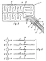
- FIG. 1 shows a first embodiment of a tempering device 11.
- the tempering device 11 is used for tempering body parts of the human or animal body. It can be used both for cooling and for heating. When used as a cooling application, the tempering device 11 has immense advantages over the previously mentioned conventional refrigeration applications such as ice cubes and liquid-filled cooling pad. The conventional applications do not allow exact temperature control, so can cause tissue damage or nerve paralysis due to low cooling temperature. With the tempering a constant temperature cooling is possible, so that it is ideal for prevention of swelling and pain.
- the tempering device has a tempering pad 12, which can be coupled to a temperature control device (not shown), can be applied to the human or animal body and can be flowed through by temperature-controlled fluid. Furthermore, at least two hose connection openings 13, 14 are provided, in each of which a hose end 15, 16 of a supply hose 17, 18 a hose assembly 19 is arranged or inserted, can be transported through the temperature-controlled fluid in the circuit between the temperature control and Temperierkissen 12.
- the tempering device 11 may also have the above-mentioned temperature control device, in which case may be part of the overall system and several tempering 12. That is, over the temperature control several Temperierkissen be supplied with tempered fluid.
- the tempering pad 12 can have a very wide variety of configurations. Depending on the geometric configuration, the tempering pad 12 is suitable for placement on corresponding areas of the head, body and limbs. Temperierkissen are z. B. can be used to hang up in the forehead, neck, eye, jaw, shoulder, hand, chest, hips, knees, calf, foot and all parts of the body where a thermotherapy is indicated.
- the tempering pad 12 is made of plastic.
- PU can be used, with which the temperature control pad 12 can be produced inexpensively, so that, for example, a single use is possible.
- the tempered fluid used is a liquid, in particular water.
- the Temperierkissen 12 has a channel assembly 20 which is formed by an inlet opening Hose connection opening 13 evenly distributed over the Temperierkissen 12 leads to a designed as an outlet hose connection opening 14. This ensures that tempered fluid passes uniformly in all areas of the Temperierkissens 12.
- the Temperierkissen 12 also still has a hose connection part 21, at which the hose connection openings 13, 14, so the inlet or outlet opening, are.
- the supply hoses 17, 18 are inseparable from the temperature control pad 12 connected, in particular, they are in the manufacture of the tempering directly into the corresponding hose connection openings 13, 14 with welded.
- the preparation of the tempering pad 12 is preferably carried out such that two layers of plastic material with the same outer dimensions superimposed and welded together at certain welds 22, depending on the course of the welds 22, a characteristic, such as meandering course of the channel assembly 20 can be specified.
- the hose ends 15, 16 of the supply hoses 17, 18 are brought between the two layers and welded with.
- the hose ends 15, 16 have a straight end, whereby a relatively sharp edge at the transition between the hose ends 15, 16 and the Temperierkissen arises.
- the material of the tempering pad is softer and more flexible than the material of the supply hoses.
- the retention means at least one Aufhalteausschnitt 23, which is introduced from an end face of the hose end 15, 16 extending in the axial direction in the hose wall.
- the Aufhalteausschnitte can be cut in a simple manner with a suitable cutting tool, in particular knives, in the hose wall.
- these containment cutouts can be produced in a simple manner.
- FIG. 2A are provided two Aufhalteausschnitte 23 which are diametrically opposed, so that two opposite tabs 24 remain.
- the Aufhalteausschnitte 23 V-like designed and have at the bottom a rounding. The depth of cut can be made variable.
- the containment cutouts 23 in the region of the end faces the hose ends 15, 16 a relatively large width, so that the lobes are designed relatively thin-walled and thus very flexurally flexible.
- two V-like containment cutouts 23 may be provided which are made narrower in comparison to embodiment 2A so that the remaining tabs 24 have a somewhat greater thickness.
- a rounding at the bottom is also provided here.
- the containment cutouts 23 may also have a U-shaped configuration, wherein preferably here too a rounding may be provided at the bottom. There are two left in plan view rectangular tabs 24 left.
- the protruding tabs 24 are also bent over, both in one direction.
- the flow cross-section for the temperature-controlled fluid does not close completely when being bent, since temperature-controlled fluid can still flow past the lugs 24 laterally via the containment cutouts.
- FIGS. 3 and 4 show a second embodiment of a tempering device 11. It differs from the embodiment described above by the different design of the retention means.
- the containment means here have a finger-like arresting attachment 25 protruding forwards from the end face of the hose end 15, 16.
- the containment approach 25 is formed by the hose wall itself, by the fact that the regions of the hose wall adjacent to the finger-like containment approach 25 are simply separated off, in particular cut away.
- the length of the containment approach 25 is variable and may, as exemplified in FIG. 3 shown dimensioned such that the containment approach to bends of the channel assembly 20 is feasible.
- the finger-like attachment approach bends through.
- the material of the supply hoses 17, 18 is stiffer than the material of the tempering pad 12, this leads to the bent finger-like attachment 25 not completely closing the flow cross-section, but at least one narrow opening also remains open, via which tempered fluid enters or leaves can flow out.
- FIGS. 5 and 6 show an embodiment of the tempering device 11 according to the invention.
- This embodiment also differs from the embodiments already described above by the different design of the retention means.
- the containment means here have at least one in the associated supply hose 17, 18, ie in the inlet or return hose, insertable, elongated insert profile 26 which is flowed around in the inserted state of tempered fluid and from the front side of the hose end 15,16 Protrusion protrudes forward.
- the insertion profile 26 can in a simple manner via the free tube ends 15, 16 optionally with a suitable Insertion means are inserted into the desired insertion position.
- the insert profile 26 is made of flexible material, so that it is possible, similar to the stop neck 25 of the second embodiment, to guide the insertion profile 26 around bends of the channel arrangement 20.
- the insertion profile 26 may also be formed as a hollow profile, then tempered fluid on the profile inside can flow in or out.
- fixing means for axial Fixation of the insertion profile 26 may be provided.
- FIGS. 6A, 6B and 6D is an accurate fit of the insertion 26 in the supply hose 17, 18 possible because tempered fluid can flow through the aforementioned flow channels between the outer wall of the insertion profile 26 and the inner wall of the supply tube 17, 18.
- FIG. 6E is a fitting fit possible because tempered fluid can flow through the profile interior.
- FIG. 6C it is necessary that the insertion profile sits with play in the supply hose so that tempered fluid can flow past.
- fixing means which are formed by a longitudinally wave-like configuration of the insertion profile, whereby the insertion profile can be clamped like a spring in the supply hose.
- FIGS. 7 and 8 show a fourth embodiment of a tempering device 11.
- the hose connection openings 13, 14 are here part of a arranged in Temperierkissen 12 hose connector 27, where the retention means are located or the retention means are assigned.
- the supply hoses 17, 18 can be detachably coupled to the hose connector 27 here.
- the two hose connection ports 13, 14 may be formed in the hose fitting 27 and each provided with a thread, in which a provided with a counter-threaded hose end can be screwed.
- a holding means is similar to the second embodiment, a finger-like
- FIG. 8B An alternative is in FIG. 8B represented here, wherein two over the outer dimension of the tempering 12 protruding connecting sleeves 29, 30 are provided, into which the hose ends 15, 16 of the supply hoses 17, 18 can be inserted.
- retention means in the form of finger-like retention lugs 28 are provided.
- the hose connectors 27 are preferably welded into the temperature control pad 12.
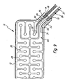
- Fig. 9 to 13 show a fifth embodiment. It differs from the embodiments described above also by the different design of the retention means. It is again here, as already shown in the third embodiment, a fixable on inlet or return hose, elongated insertion profile 26 is provided, which can be flowed around in the inserted state of tempered fluid and from the front side of the hose end 15, 16 with supernatant forward protrudes.
- the insertion profile 26 can in principle be divided into three sections. There is provided a front insertion section 31, which has a larger cross-section with respect to the rest of the insertion profile 26.
- the insertion section 31 is shown here by way of example in the form of a ball head. However, other geometries are conceivable.
- the insertion section 31 ensures that the insertion profile 26 can be easily inserted into the associated supply hose 17, 18 and can be passed through it in a manner which will be described in more detail below, until a part of the insertion profile 26 engages Projection from the associated supply hose 17, 18 protrudes.
- the insertion section 31 ensures easy insertion into the associated hose connection openings 13, 14 on the temperature control pad 12.
- a bending flexible bending section 32 In the insertion behind the insertion section is a bending flexible bending section 32, with respect to the insertion section 31 of smaller cross-section.
- the bending section 32 is, as in particular in Fig. 10 illustrated, shown by way of example in flat profile-like design.
- the bending section 32 ensures that the insertion profile 26 can also be guided around bends of the channel arrangement 20.
- a base portion 33 is arranged, as in the FIGS. 10 and 12 shown, the majority of the insertion profile 26 occupies.
- the base portion 33 is like the bending portion 32 suitably designed flat-profile or web-shaped and preferably has a double-T-like cross-section, with 33 thickenings 34 are located on the two opposite narrow sides of the base portion.
- the fixing means in the form of at least one of the outer circumference of the insertion profile 26 projecting outward Fixiervorsprungs 35 in the form of a fixing tongue.
- the fixing tongue is braced in the manner of predetermining an axial fixing position of the insertion profile 26 in the hose on the end face of the hose end 15, 16.
- fixing tongues are arranged in the region of the thickening on the narrow sides of the base portion 33 and protrude from there to the outside.
- the fixing tongues are flexurally flexible and, when the insertion profile 26 is inserted, can be resiliently compressed by the inside dimension of the supply hose 17, 18, wherein after passing through the hose end 15, 16 a resilient snapping back takes place.
- a first row 36a of fixing tongues arranged one after the other in the profile longitudinal direction is provided, which is located on the narrow side of the base portion 33 equipped with the thickening 34, and a second row 36b which is provided on the opposite, likewise with a thickening 34 Narrow side of the base portion 33 is provided.
- the fixing tongues are arranged alternately, wherein at the level of the gap between two successively arranged fixing tongues of a row 36a, a fixing tongue of the other row 36b is formed and vice versa.
- a handling section 37 in particular in the form of a cylindrical pin, which allows a fixation of the insertion profile 26 to a suitable insertion tool (not shown).
- the supply hoses 17, 18 are first connected to the associated hose connection openings 13, 14 of the temperature control pad 12, in particular welded thereto. Thereafter, the insertion tool is fixed to the round pin of the insertion profile 26 and the insertion profile 26 with the insertion section 31 ahead in the associated supply hose 17, 18 introduced. With the help of the insertion tool, the insertion profile 26 is then pushed through the supply tube 17, 18, wherein the bending-flexible fixing tongues are compressed by the inner dimension of the tube. The insertion profile 26 is pushed through the associated supply hose 17, 18 until it exits at the other hose end 15, 16 again.
- the fixing tongues thus form barbs which prevent the insertion profile 26 from slipping back.
- the fixing tongues also predetermine the axial fixing position of the insertion profile 26 in the associated supply hose 17, 18. A further slipping out of the insertion profile in the insertion direction from the supply tube 17, 18 out is ensured by the voltage applied to the inner wall of the supply tube 17, 18 fixing tongues that have not yet emerged from the hose end 15, 16.
- the part of the insertion profile 26 that has emerged from the associated hose end 15, 16 can adapt to the bends in the channel arrangement 20 of the temperature control pad 12 as a result of its flexurally flexible bending section 32.
Landscapes
- Thermotherapy And Cooling Therapy Devices (AREA)
Abstract
Claims (13)
- Dispositif de régulation de la température servant à réguler la température de zones corporelles du corps humain, avec un coussin de régulation de la température (12), qui peut être couplé à un appareil de régulation de la température, appliqué sur le corps et parcouru par un fluide à température régulée, avec au moins deux ouvertures de raccordement de tuyau (13, 14), dans chacune desquelles une extrémité de tuyau (15, 16) d'un tuyau d'alimentation (17, 18) d'un agencement de tuyaux (19) est disposée ou peut être introduite, par lequel un fluide à température régulée peut être transporté en circuit entre l'appareil de régulation de la température et le coussin de régulation de la température (12), un fluide à température régulée circulant chaque fois à travers une section transversale d'écoulement dans le coussin de régulation de la température (12) et hors du coussin de régulation de la température (12), des moyens d'ouverture (23, 25, 26), qui maintiennent la section transversale d'écoulement au moins partiellement ouverte lors du pliage du coussin de régulation de la température (12) dans la région des extrémités de tuyau (15, 16), étant prévus, les moyens d'ouverture présentant au moins un moyen d'insertion, qui est saillant avec un dépassement vers l'avant à partir de la face frontale de l'extrémité de tuyau (15, 16), caractérisé en ce que le moyen d'insertion est un profilé d'insertion allongé (26), insérable dans le tuyau d'alimentation associé (17, 18), qui à l'état inséré peut être contourné par le fluide à température régulée, et en ce qu'il est prévu des moyens de fixation pour la fixation axiale de la position d'insertion souhaitée du profilé d'insertion (26).
- Dispositif de régulation de la température selon la revendication 1, caractérisé en ce que les moyens d'ouverture (23, 25, 26) sont réalisés de telle manière qu'il subsiste une souplesse de flexion du coussin de régulation de la température (12) dans la région des extrémités de tuyau (15, 16).
- Dispositif de régulation de la température selon la revendication 1 ou 2, caractérisé en ce que les moyens d'ouverture (23, 25, 26) sont associés aux extrémités de tuyau (15, 16).
- Dispositif de régulation de la température selon l'une quelconque des revendications précédentes, caractérisé en ce que les moyens d'ouverture présentent au moins une section d'ouverture (23) introduite dans la paroi du tuyau et s'étendant en direction axiale à partir d'une face frontale de l'extrémité de tuyau (15, 16).
- Dispositif de régulation de la température selon la revendication 4, caractérisé en ce qu'il est prévu deux sections d'ouverture (23), en particulier diamétralement opposées, ou plus de deux sections d'ouverture (23).
- Dispositif de régulation de la température selon l'une quelconque des revendications précédentes, caractérisé en ce que les moyens d'ouverture présentent un prolongement d'ouverture (25) en saillie vers l'avant à partir de la face frontale de l'extrémité de tuyau (15, 16).
- Dispositif de régulation de la température selon la revendication 1, caractérisé en ce que les moyens de fixation présentent au moins une protubérance de fixation (35) saillante vers l'extérieur sur un contour extérieur du profilé d'insertion (26), qui s'appuie à la manière d'un rétro-crochet sur la face frontale de l'extrémité de tuyau (15, 16) pour préciser une position de fixation axiale du profilé d'insertion (26) dans le tuyau d'alimentation (17, 18).
- Dispositif de régulation de la température selon la revendication 7, caractérisé en ce que ladite au moins une protubérance de fixation (35) est formée par au moins une languette de fixation souple en flexion, qui est élastiquement compressible lors de l'introduction du profilé d'insertion (26) à travers une dimension intérieure du tuyau d'alimentation (17, 18) et s'écarte de nouveau élastiquement après avoir franchi l'extrémité de tuyau (15, 16).
- Dispositif de régulation de la température selon la revendication 8, caractérisé en ce que plusieurs protubérances de fixation (35) sont disposées l'une derrière l'autre dans la direction longitudinale de profilé du profilé d'insertion (26).
- Dispositif de régulation de la température selon la revendication 9, caractérisé en ce qu'il est prévu au moins deux rangées de protubérances de fixation (35) disposées respectivement l'une derrière l'autre, les protubérances (35) d'une première rangée (36a) étant de préférence décalées, dans la direction longitudinale de profilé, par rapport aux protubérances de fixation d'une seconde rangée (36b).
- Dispositif de régulation de la température selon l'une quelconque des revendications précédentes, caractérisé en ce que les ouvertures de raccordement de tuyau (13, 14) font partie d'une pièce de raccordement de tuyau (27) disposée dans le coussin de régulation de la température (12), sur laquelle les moyens d'ouverture (25) sont situés ou à laquelle les moyens d'ouverture (25) sont associés.
- Dispositif de régulation de la température selon l'une quelconque des revendications 1 à 11, caractérisé en ce que le profilé d'insertion (26) comprend une section d'introduction (31) présentant, par rapport au reste du profilé d'insertion (26), une plus grande section transversale destinée à l'introduction dans l'ouverture de raccordement de tuyau associée (13, 14) du coussin de régulation de la température (12).
- Dispositif de régulation de la température selon l'une quelconque des revendications 1 à 12, caractérisé en ce que le profilé d'insertion (26) présente une section de flexion souple en flexion (33), se raccordant à la section d'introduction (31) en particulier dans la direction longitudinale du profilé, par laquelle un guidage du profilé d'insertion (26) dans les courbes du réseau de canaux (20) du coussin de régulation de la température (12) est possible.
Priority Applications (1)
| Application Number | Priority Date | Filing Date | Title |
|---|---|---|---|
| EP08758435A EP2194940B1 (fr) | 2007-10-11 | 2008-05-09 | Dispositif de régulation de la température servant à réguler la température de parties cutanées du corps humain |
Applications Claiming Priority (3)
| Application Number | Priority Date | Filing Date | Title |
|---|---|---|---|
| PCT/EP2007/008829 WO2009049639A1 (fr) | 2007-10-11 | 2007-10-11 | Dispositif de régulation de la température |
| EP08758435A EP2194940B1 (fr) | 2007-10-11 | 2008-05-09 | Dispositif de régulation de la température servant à réguler la température de parties cutanées du corps humain |
| PCT/EP2008/003747 WO2009049688A1 (fr) | 2007-10-11 | 2008-05-09 | Dispositif de régulation de la température servant à réguler la température de parties cutanées du corps humain |
Publications (2)
| Publication Number | Publication Date |
|---|---|
| EP2194940A1 EP2194940A1 (fr) | 2010-06-16 |
| EP2194940B1 true EP2194940B1 (fr) | 2011-09-21 |
Family
ID=42167694
Family Applications (1)
| Application Number | Title | Priority Date | Filing Date |
|---|---|---|---|
| EP08758435A Active EP2194940B1 (fr) | 2007-10-11 | 2008-05-09 | Dispositif de régulation de la température servant à réguler la température de parties cutanées du corps humain |
Country Status (1)
| Country | Link |
|---|---|
| EP (1) | EP2194940B1 (fr) |
Cited By (1)
| Publication number | Priority date | Publication date | Assignee | Title |
|---|---|---|---|---|
| WO2022101320A1 (fr) | 2020-11-11 | 2022-05-19 | Hilotherm Holding Ag | Appareil pour le traitement par thérapie thermique d'une région sélectionnée du corps d'un être humain ou d'un animal et procédé de fonctionnement dudit appareil |
-
2008
- 2008-05-09 EP EP08758435A patent/EP2194940B1/fr active Active
Cited By (2)
| Publication number | Priority date | Publication date | Assignee | Title |
|---|---|---|---|---|
| WO2022101320A1 (fr) | 2020-11-11 | 2022-05-19 | Hilotherm Holding Ag | Appareil pour le traitement par thérapie thermique d'une région sélectionnée du corps d'un être humain ou d'un animal et procédé de fonctionnement dudit appareil |
| EP4000567A1 (fr) | 2020-11-11 | 2022-05-25 | Hilotherm Holding AG | Dispositif de traitement thérapeutique par la chaleur d'une zone corporelle sélectionnée d'un humain ou d'un animal et procédé de fonctionnement dudit appareil |
Also Published As
| Publication number | Publication date |
|---|---|
| EP2194940A1 (fr) | 2010-06-16 |
Similar Documents
| Publication | Publication Date | Title |
|---|---|---|
| DE3785236T2 (de) | Abflusskatheter. | |
| DE60032491T2 (de) | Wärmetauschkatheter mit diskreten wärmetauschelementen | |
| DE2745317C2 (fr) | ||
| DE69000777T2 (de) | Isolierendes, nichtknickbares y-verbindungsstueck fuer die arthroskopische chirurgie und herstellungsverfahren. | |
| EP2177338B1 (fr) | Elément de chauffage tubulaire doté d'un capteur de température | |
| AT11724U1 (de) | Beissvorrichtung | |
| DE1550306A1 (de) | Thermisch gesteuertes Mischventil | |
| EP0650376B1 (fr) | Dispositif visant a chauffer des liquides dans le domaine d'applications medicales | |
| EP2801334B1 (fr) | Dispositif de dilatation et revêtement extensible pour un instrument de dilatation | |
| DE60127812T2 (de) | Wärme austauschende katheter mit mehreren lumen | |
| CH624570A5 (en) | Medullary pin and targeting device for anchoring it in the medullary canal | |
| CH636262A5 (de) | Therapeutische packung. | |
| EP2194940B1 (fr) | Dispositif de régulation de la température servant à réguler la température de parties cutanées du corps humain | |
| DE60119980T2 (de) | Verstellbarer dampfinjektor | |
| WO2009049688A1 (fr) | Dispositif de régulation de la température servant à réguler la température de parties cutanées du corps humain | |
| DE3410413A1 (de) | Temperiersystem | |
| EP3069699A1 (fr) | Dispositif de traitement de la chaleur destine a etre utilise dans le traitement par la chaleur du corps humain | |
| EP3342378B1 (fr) | Manchette destinée à être utilisée dans le traitement par la chaleur du corps humain | |
| EP3482644B1 (fr) | Dispositif de traitement destiné au traitement par thermothérapie des deux seins d'une patiente | |
| DE102013112650B4 (de) | Ballonkatheter mit einem Katheterschlauch und einem Ballon und Ballonkatheter zum endovaskulären Temperieren von Blut | |
| DE202018107423U1 (de) | Manschette zur Verwendung bei der wärmetherapeutischen Behandlung des menschlichen Körpers | |
| DE102011100616A1 (de) | Vorrichtung und Verwendung eines Systems zur Hypothermie sowie Verfahren zur Erhöhung des Energieverbrauchs des menschlichen Körpers | |
| DE102018122846A1 (de) | Infusionssystem und -verfahren zur Temperatursteuerung | |
| DE102007040487A1 (de) | Temperiereinrichtung | |
| DE202007003157U1 (de) | Vorrichtung zur Kälte- oder Wärmebehandlung von Extremitäten von Wirbeltieren |
Legal Events
| Date | Code | Title | Description |
|---|---|---|---|
| PUAI | Public reference made under article 153(3) epc to a published international application that has entered the european phase |
Free format text: ORIGINAL CODE: 0009012 |
|
| 17P | Request for examination filed |
Effective date: 20100326 |
|
| AK | Designated contracting states |
Kind code of ref document: A1 Designated state(s): AT BE BG CH CY CZ DE DK EE ES FI FR GB GR HR HU IE IS IT LI LT LU LV MC MT NL NO PL PT RO SE SI SK TR |
|
| AX | Request for extension of the european patent |
Extension state: AL BA MK RS |
|
| DAX | Request for extension of the european patent (deleted) | ||
| GRAP | Despatch of communication of intention to grant a patent |
Free format text: ORIGINAL CODE: EPIDOSNIGR1 |
|
| RTI1 | Title (correction) |
Free format text: TEMPERATURE CONTROL DEVICE FOR CONTROLLING THE TEMPERATURE OF AREAS OF THE SKIN OF THE HUMAN BODY |
|
| GRAS | Grant fee paid |
Free format text: ORIGINAL CODE: EPIDOSNIGR3 |
|
| GRAA | (expected) grant |
Free format text: ORIGINAL CODE: 0009210 |
|
| AK | Designated contracting states |
Kind code of ref document: B1 Designated state(s): AT BE BG CH CY CZ DE DK EE ES FI FR GB GR HR HU IE IS IT LI LT LU LV MC MT NL NO PL PT RO SE SI SK TR |
|
| REG | Reference to a national code |
Ref country code: GB Ref legal event code: FG4D Free format text: NOT ENGLISH |
|
| REG | Reference to a national code |
Ref country code: CH Ref legal event code: EP |
|
| REG | Reference to a national code |
Ref country code: IE Ref legal event code: FG4D Free format text: LANGUAGE OF EP DOCUMENT: GERMAN |
|
| REG | Reference to a national code |
Ref country code: CH Ref legal event code: NV Representative=s name: ISLER & PEDRAZZINI AG |
|
| REG | Reference to a national code |
Ref country code: DE Ref legal event code: R096 Ref document number: 502008004967 Country of ref document: DE Effective date: 20111201 |
|
| REG | Reference to a national code |
Ref country code: NL Ref legal event code: VDEP Effective date: 20110921 |
|
| PG25 | Lapsed in a contracting state [announced via postgrant information from national office to epo] |
Ref country code: SE Free format text: LAPSE BECAUSE OF FAILURE TO SUBMIT A TRANSLATION OF THE DESCRIPTION OR TO PAY THE FEE WITHIN THE PRESCRIBED TIME-LIMIT Effective date: 20110921 Ref country code: HR Free format text: LAPSE BECAUSE OF FAILURE TO SUBMIT A TRANSLATION OF THE DESCRIPTION OR TO PAY THE FEE WITHIN THE PRESCRIBED TIME-LIMIT Effective date: 20110921 Ref country code: FI Free format text: LAPSE BECAUSE OF FAILURE TO SUBMIT A TRANSLATION OF THE DESCRIPTION OR TO PAY THE FEE WITHIN THE PRESCRIBED TIME-LIMIT Effective date: 20110921 Ref country code: NO Free format text: LAPSE BECAUSE OF FAILURE TO SUBMIT A TRANSLATION OF THE DESCRIPTION OR TO PAY THE FEE WITHIN THE PRESCRIBED TIME-LIMIT Effective date: 20111221 Ref country code: LT Free format text: LAPSE BECAUSE OF FAILURE TO SUBMIT A TRANSLATION OF THE DESCRIPTION OR TO PAY THE FEE WITHIN THE PRESCRIBED TIME-LIMIT Effective date: 20110921 |
|
| LTIE | Lt: invalidation of european patent or patent extension |
Effective date: 20110921 |
|
| PG25 | Lapsed in a contracting state [announced via postgrant information from national office to epo] |
Ref country code: SI Free format text: LAPSE BECAUSE OF FAILURE TO SUBMIT A TRANSLATION OF THE DESCRIPTION OR TO PAY THE FEE WITHIN THE PRESCRIBED TIME-LIMIT Effective date: 20110921 Ref country code: LV Free format text: LAPSE BECAUSE OF FAILURE TO SUBMIT A TRANSLATION OF THE DESCRIPTION OR TO PAY THE FEE WITHIN THE PRESCRIBED TIME-LIMIT Effective date: 20110921 Ref country code: CY Free format text: LAPSE BECAUSE OF FAILURE TO SUBMIT A TRANSLATION OF THE DESCRIPTION OR TO PAY THE FEE WITHIN THE PRESCRIBED TIME-LIMIT Effective date: 20110921 Ref country code: GR Free format text: LAPSE BECAUSE OF FAILURE TO SUBMIT A TRANSLATION OF THE DESCRIPTION OR TO PAY THE FEE WITHIN THE PRESCRIBED TIME-LIMIT Effective date: 20111222 |
|
| REG | Reference to a national code |
Ref country code: IE Ref legal event code: FD4D |
|
| PG25 | Lapsed in a contracting state [announced via postgrant information from national office to epo] |
Ref country code: CZ Free format text: LAPSE BECAUSE OF FAILURE TO SUBMIT A TRANSLATION OF THE DESCRIPTION OR TO PAY THE FEE WITHIN THE PRESCRIBED TIME-LIMIT Effective date: 20110921 Ref country code: IS Free format text: LAPSE BECAUSE OF FAILURE TO SUBMIT A TRANSLATION OF THE DESCRIPTION OR TO PAY THE FEE WITHIN THE PRESCRIBED TIME-LIMIT Effective date: 20120121 Ref country code: IE Free format text: LAPSE BECAUSE OF FAILURE TO SUBMIT A TRANSLATION OF THE DESCRIPTION OR TO PAY THE FEE WITHIN THE PRESCRIBED TIME-LIMIT Effective date: 20110921 Ref country code: SK Free format text: LAPSE BECAUSE OF FAILURE TO SUBMIT A TRANSLATION OF THE DESCRIPTION OR TO PAY THE FEE WITHIN THE PRESCRIBED TIME-LIMIT Effective date: 20110921 |
|
| PG25 | Lapsed in a contracting state [announced via postgrant information from national office to epo] |
Ref country code: PT Free format text: LAPSE BECAUSE OF FAILURE TO SUBMIT A TRANSLATION OF THE DESCRIPTION OR TO PAY THE FEE WITHIN THE PRESCRIBED TIME-LIMIT Effective date: 20120123 Ref country code: PL Free format text: LAPSE BECAUSE OF FAILURE TO SUBMIT A TRANSLATION OF THE DESCRIPTION OR TO PAY THE FEE WITHIN THE PRESCRIBED TIME-LIMIT Effective date: 20110921 Ref country code: NL Free format text: LAPSE BECAUSE OF FAILURE TO SUBMIT A TRANSLATION OF THE DESCRIPTION OR TO PAY THE FEE WITHIN THE PRESCRIBED TIME-LIMIT Effective date: 20110921 Ref country code: EE Free format text: LAPSE BECAUSE OF FAILURE TO SUBMIT A TRANSLATION OF THE DESCRIPTION OR TO PAY THE FEE WITHIN THE PRESCRIBED TIME-LIMIT Effective date: 20110921 Ref country code: RO Free format text: LAPSE BECAUSE OF FAILURE TO SUBMIT A TRANSLATION OF THE DESCRIPTION OR TO PAY THE FEE WITHIN THE PRESCRIBED TIME-LIMIT Effective date: 20110921 |
|
| PLBE | No opposition filed within time limit |
Free format text: ORIGINAL CODE: 0009261 |
|
| STAA | Information on the status of an ep patent application or granted ep patent |
Free format text: STATUS: NO OPPOSITION FILED WITHIN TIME LIMIT |
|
| PG25 | Lapsed in a contracting state [announced via postgrant information from national office to epo] |
Ref country code: DK Free format text: LAPSE BECAUSE OF FAILURE TO SUBMIT A TRANSLATION OF THE DESCRIPTION OR TO PAY THE FEE WITHIN THE PRESCRIBED TIME-LIMIT Effective date: 20110921 |
|
| 26N | No opposition filed |
Effective date: 20120622 |
|
| REG | Reference to a national code |
Ref country code: DE Ref legal event code: R097 Ref document number: 502008004967 Country of ref document: DE Effective date: 20120622 |
|
| BERE | Be: lapsed |
Owner name: HILOTHERM HOLDING A.G. Effective date: 20120531 |
|
| PG25 | Lapsed in a contracting state [announced via postgrant information from national office to epo] |
Ref country code: MC Free format text: LAPSE BECAUSE OF NON-PAYMENT OF DUE FEES Effective date: 20120531 |
|
| PG25 | Lapsed in a contracting state [announced via postgrant information from national office to epo] |
Ref country code: BE Free format text: LAPSE BECAUSE OF NON-PAYMENT OF DUE FEES Effective date: 20120531 |
|
| PG25 | Lapsed in a contracting state [announced via postgrant information from national office to epo] |
Ref country code: ES Free format text: LAPSE BECAUSE OF FAILURE TO SUBMIT A TRANSLATION OF THE DESCRIPTION OR TO PAY THE FEE WITHIN THE PRESCRIBED TIME-LIMIT Effective date: 20120101 |
|
| PG25 | Lapsed in a contracting state [announced via postgrant information from national office to epo] |
Ref country code: BG Free format text: LAPSE BECAUSE OF FAILURE TO SUBMIT A TRANSLATION OF THE DESCRIPTION OR TO PAY THE FEE WITHIN THE PRESCRIBED TIME-LIMIT Effective date: 20111221 |
|
| PG25 | Lapsed in a contracting state [announced via postgrant information from national office to epo] |
Ref country code: MT Free format text: LAPSE BECAUSE OF FAILURE TO SUBMIT A TRANSLATION OF THE DESCRIPTION OR TO PAY THE FEE WITHIN THE PRESCRIBED TIME-LIMIT Effective date: 20110921 |
|
| PG25 | Lapsed in a contracting state [announced via postgrant information from national office to epo] |
Ref country code: TR Free format text: LAPSE BECAUSE OF FAILURE TO SUBMIT A TRANSLATION OF THE DESCRIPTION OR TO PAY THE FEE WITHIN THE PRESCRIBED TIME-LIMIT Effective date: 20110921 |
|
| PG25 | Lapsed in a contracting state [announced via postgrant information from national office to epo] |
Ref country code: LU Free format text: LAPSE BECAUSE OF NON-PAYMENT OF DUE FEES Effective date: 20120509 |
|
| REG | Reference to a national code |
Ref country code: AT Ref legal event code: MM01 Ref document number: 525047 Country of ref document: AT Kind code of ref document: T Effective date: 20130509 |
|
| PG25 | Lapsed in a contracting state [announced via postgrant information from national office to epo] |
Ref country code: HU Free format text: LAPSE BECAUSE OF FAILURE TO SUBMIT A TRANSLATION OF THE DESCRIPTION OR TO PAY THE FEE WITHIN THE PRESCRIBED TIME-LIMIT Effective date: 20080509 |
|
| PG25 | Lapsed in a contracting state [announced via postgrant information from national office to epo] |
Ref country code: AT Free format text: LAPSE BECAUSE OF NON-PAYMENT OF DUE FEES Effective date: 20130509 |
|
| REG | Reference to a national code |
Ref country code: FR Ref legal event code: PLFP Year of fee payment: 8 |
|
| REG | Reference to a national code |
Ref country code: DE Ref legal event code: R082 Ref document number: 502008004967 Country of ref document: DE Representative=s name: WALLINGER RICKER SCHLOTTER TOSTMANN PATENT- UN, DE |
|
| REG | Reference to a national code |
Ref country code: FR Ref legal event code: PLFP Year of fee payment: 9 |
|
| REG | Reference to a national code |
Ref country code: FR Ref legal event code: PLFP Year of fee payment: 10 |
|
| REG | Reference to a national code |
Ref country code: FR Ref legal event code: PLFP Year of fee payment: 11 |
|
| P01 | Opt-out of the competence of the unified patent court (upc) registered |
Effective date: 20230505 |
|
| PGFP | Annual fee paid to national office [announced via postgrant information from national office to epo] |
Ref country code: IT Payment date: 20230531 Year of fee payment: 16 Ref country code: CH Payment date: 20230602 Year of fee payment: 16 |
|
| PGFP | Annual fee paid to national office [announced via postgrant information from national office to epo] |
Ref country code: GB Payment date: 20240522 Year of fee payment: 17 |
|
| PGFP | Annual fee paid to national office [announced via postgrant information from national office to epo] |
Ref country code: DE Payment date: 20240517 Year of fee payment: 17 |
|
| PGFP | Annual fee paid to national office [announced via postgrant information from national office to epo] |
Ref country code: FR Payment date: 20240523 Year of fee payment: 17 |