EP2194714A1 - Procédé de détection du mode film ou du mode caméra - Google Patents
Procédé de détection du mode film ou du mode caméra Download PDFInfo
- Publication number
- EP2194714A1 EP2194714A1 EP09177296A EP09177296A EP2194714A1 EP 2194714 A1 EP2194714 A1 EP 2194714A1 EP 09177296 A EP09177296 A EP 09177296A EP 09177296 A EP09177296 A EP 09177296A EP 2194714 A1 EP2194714 A1 EP 2194714A1
- Authority
- EP
- European Patent Office
- Prior art keywords
- video
- value
- video frame
- sequence
- histogram
- Prior art date
- Legal status (The legal status is an assumption and is not a legal conclusion. Google has not performed a legal analysis and makes no representation as to the accuracy of the status listed.)
- Granted
Links
- 238000000034 method Methods 0.000 title claims abstract description 39
- 238000001514 detection method Methods 0.000 title claims abstract description 15
- 238000001914 filtration Methods 0.000 claims description 6
- 230000002123 temporal effect Effects 0.000 claims description 4
- 238000006243 chemical reaction Methods 0.000 description 10
- 230000000694 effects Effects 0.000 description 8
- 230000006870 function Effects 0.000 description 3
- 230000001419 dependent effect Effects 0.000 description 2
- 230000003416 augmentation Effects 0.000 description 1
- 230000000717 retained effect Effects 0.000 description 1
- 230000001131 transforming effect Effects 0.000 description 1
Images


Classifications
-
- H—ELECTRICITY
- H04—ELECTRIC COMMUNICATION TECHNIQUE
- H04N—PICTORIAL COMMUNICATION, e.g. TELEVISION
- H04N7/00—Television systems
- H04N7/01—Conversion of standards, e.g. involving analogue television standards or digital television standards processed at pixel level
- H04N7/0112—Conversion of standards, e.g. involving analogue television standards or digital television standards processed at pixel level one of the standards corresponding to a cinematograph film standard
- H04N7/0115—Conversion of standards, e.g. involving analogue television standards or digital television standards processed at pixel level one of the standards corresponding to a cinematograph film standard with details on the detection of a particular field or frame pattern in the incoming video signal, e.g. 3:2 pull-down pattern
Definitions
- the present invention relates to the processing of video signals and more specifically to a method of detection of film or camera mode of a sequence of video frames.
- the detection of film mode is traditionally used in modern televisions to determine the processes to apply to images received with a view to improving their display quality.
- This frequency change consists for example in duplicating the frames of the input sequence, as shown in figure 1 .
- the sequence to be converted noted as ABC, comprises three frames. The first frame represents image A, the second frame represents image B and the third frame represents image C.
- the duplication operation consists in transforming this sequence of three frames into a sequence of 6 frames, AABBCC, having a double frequency.
- the two first frames of the transformed sequence are identical and represent the image A.
- the two following frames represent the image B and the two last frames represent the image C.
- This duplication operation results in suppressing the flicker effect during the displaying of the new sequence but however creates a judder effect when the displayed images comprise motion.
- the frame representing image A in the input sequence is converted, in the output sequence, into a frame representing image A and a frame representing a motion compensated image A'.
- image A' the motion is estimated between image A and the next image, which is image B, and an intermediary image is created A' based on the motion estimated between these two images.
- the frame representing image B is converted, in the output sequence, into a frame representing the image B and a frame representing a motion compensated image B' and the frame representing image C is converted, in the output sequence, into a frame representing the image C and a frame representing a motion compensated image C'.
- This increase in frequency with motion compensation enables suppressing the flicker effect while conserving a fluidity of motion in the sequence.
- This type of processing is however only valid when the input sequence does not comprise duplicated frames, for example when the sequence is in film format (24 or 25 images per second) or in camera format (50 or 60 images per second).
- this processing is not applicable when an input sequence, of film format (24 or 25 images per second) origin, has been transformed into a telecine stream by a format conversion of 2:2 pull-down conversion type or a 3:2 pull-down conversion type with a view to its display on a television (50 or 60 images per second).
- the 2:2 pull-down conversion is used to pass from 25 images per second (film format) to 50 images per second (PAL/SECAM format). This conversion consists in duplicating each input frame.
- the 3:2 pull-down conversion is used to pass from 24 images per second (film format) to 60 images per second (NTSC format).
- Each pair of consecutive input frames is then converted into 5 output frames, the three first output frames being identical to the first input frame of the pair and the two other output frames being identical to the second input frame of the pair.
- the purpose of the invention is to propose a method for detection of the film mode of a sequence of video frames requiring a small quantity of data to be stored, the data can then be stored in the internal memory of an FPGA circuit.
- the present invention relates to a method for detection of film mode or camera mode of a sequence comprising at least three consecutive video frames, characterized in that it comprises the following steps:
- This method essentially requires the storage of two histograms for the step of calculation of the histogram difference of each video frame.
- the size of each histogram being in the order of a Kilobyte, the two histograms can therefore be stored locally in a FPGA type programmable circuit.
- said mode information also identifies the film mode type of the sequence, for example the film mode 2:2 (sequence initially in film format and having been transformed by a 2:2 pull-down conversion) or the film mode 3:2 (sequence initially in film format and having been transformed by a 3:2 pull-down conversion).
- mode information is generated for each video frame of the sequence, said mode information also identifying if the video frame considered is a duplicated video frame or not.
- said at least one comparison value belongs to a group comprising:
- the histogram difference value for a current video frame is determined in the following way:
- the histogram difference value for a current video frame is determined in the following way:
- This embodiment variant enables overcoming of a possible video level offset of the current video frame with respect to those of the next video frame or the inverse.
- the comparison step intended to generate difference parameters can also be realized in different ways.
- the histogram difference value is compared with a non-null predetermined threshold value that is a function of the number of pixels contained in the video frames and a predetermined maximum noise allocating said video frames and to the resemblance parameter of the considered video frame are allocated a first value, for example the value "1", if the histogram difference value of the considered video frame is greater than said threshold value and a second value, for example the value "0" if not.
- the first value of the difference indicates that the considered video frame is different to the next video frame and the second value of the resemblance parameter indicates that the considered video frame is noticeably identical to the next video frame.
- the determination of the resemblance parameter is very dependent on the threshold value, which is very dependent on the predetermined maximum noise.
- the histogram difference value of said current video frame is compared with the histogram difference value of the preceding video frame and with the histogram difference value of the next video frame, then a first value, for example the value "1" is allocated to the difference parameter of the current video frame, if said histogram difference value of said current video frame is greater than, at the same time, said histogram difference value of said next video frame and said histogram difference value of said preceding video frame and a second value, for example the value "0" if not.
- the resemblance parameter value indicates that the video frame considered is different to the next video frame and the second resemblance parameter value indicates that the considered video frame is noticeably identical to the next video frame.
- the method of the invention also comprises, prior to the step of determination of video level histograms, a step of spatial filtering of video frames of the sequence in order to smooth their video content and thus reduce the influence of noise content in the video frames on the detection.
- the method of the invention also comprises, prior to the step of comparison of the pattern formed by the difference parameters to the predetermined patterns, a step of temporal filtering of said difference parameters sequence.
- a mode information is generated for each video frame of said sequence, said mode information also comprising a bit indicating if said video frame is a source video frame or not.
- the invention also relates to a device for detection of the film mode or camera mode of a sequence comprising at least three consecutive video frames, characterized in that it comprises:
- video frame is used to designate a frame corresponding to an image or part of an image (for example, a half-image in the case of an interlaced scanning).
- This video frame can indifferently belong to a sequence in film mode or video mode.
- a sequence of video frames in film mode designates a sequence of frames comprising one or more frames duplicated following a 2:2 or 3:2 format conversion.
- other format conversions exist, such as 2:3 or 3:2:3:2:2, but we restrict our here to the detection of sequences in 3:2 or 2:2 film mode.
- a sequence of video frames in video mode or camera mode designates a sequence of video frame in camera format not comprising duplicated frames.
- a source video frame designates a non-duplicated video frame from a sequence of video frames forming a film (24 or 25 images per second) or in video format (50 or 60 images per second).
- the detection of film or camera mode of the sequence is based on the calculation and comparison of histograms of video levels of video frames of the sequence to be analysed.
- FIG 3 A flowchart of steps of the method of the invention is shown in figure 3 . These steps are also shown by the embodiment represented in figure 4 . In this example the method is applied to 4 consecutive video frames referenced T, T+1, T+2 and T+3.
- a histogram of video levels is determined for each video frame of the sequence. Thus are determined, for each video level, its occurrence in the video frame being considered. If the video levels are coded on 8 bits, 256 occurrence values are then obtained each associated with a specific video level. In the example of figure 4 , the histogram of video levels of each of the 4 video frames is calculated. 4 histograms are then obtained noted as H T , H T+1 , H T+2 and H T+3 .
- a value representative of the difference between the video frame being considered and the histogram of the next video frame is then calculated for each of the video frames.
- This value referred to as histogram difference value and noted as D T for the frame T, is for example obtained in the following way: D T ⁇ ⁇ i ⁇ 0 255 H T i ⁇ H T ⁇ 1 i
- the video levels of video frames are coded on 8 bits and have a value comprised between 0 and 255.
- step E2 3 histogram difference values noted as D T , D T+1 and D T+2 respectively for the video frames T, T+1 and T+2.
- the value of the histogram difference D T is calculated differently to overcome a noise that would offset the video levels of one video frame with respect to another.
- for each video level i are calculated, not only, the difference between its occurrence value in the frame T and its occurrence value in the frame T+1 but also the difference between its occurrence value in the frame T and the occurrence value of the neighbouring video levels i+j in the frame T+1 and only the minimum difference value is retained.
- the value of the histogram difference of the current video frame is compared to at least one other histogram difference value or one predetermined threshold value to deduce a difference parameter, noted as P T for the current video frame T, representative of the character different or not of the current video frame with respect to the next video frame. If the two video frames are different, a value "1" is assigned to the difference parameter of the current video frame and if not it is assigned a value "0".
- the histogram difference parameter is compared to a predetermined threshold value S0.
- This value is not null as account must be taken of a possible noise affecting the compared video frames.
- This threshold value S0 is a function of the number of pixels in the considered video frame and a maximum noise affecting each video frame. If the histogram difference value is greater than or equal to the threshold value S0, the value "1" is assigned the difference parameter P T and if the histogram difference value is less than the threshold value S0, it is assigned the value "0".
- This threshold value S0 is a number of pixels and is for example equal to a percentage of the total number of pixels of the video frame, this percentage defining the maximum number of pixels affected by noise in the video frame.
- the histogram difference value of the current video frame is compared to those of the next video frame and the preceding video frame. For example, for a current frame T, a value "I" is assigned to the difference parameter P T if the two following conditions are respected:
- This second embodiment of the step E3 has the advantage of not using a threshold value as defined in the preceding embodiment.
- step E3 comparing only the histogram difference D T with one or other of the histogram differences D T+1 or D T-1 and possibly with a threshold value, can be imagined.
- the last step, referenced E4, of the method of the invention consists in comparing the pattern formed by the difference parameters of video frames determined in step E3 with the predetermined patterns corresponding to the camera mode and to different film modes to deduce if the sequence of video frames processed is in camera mode or in film mode.
- this comparison of patterns also enables to determine the type of film mode of the sequence, for example a 2:2 film mode or a 3:2 film mode, and the position of source video frames (non-duplicated video frames) in the sequence.
- a pattern formed of two consecutive difference parameters P T and P T+1 suffices to differentiate a sequence in camera mode and a sequence in film mode.
- a pattern 11 corresponds to the camera mode and a pattern 01 or 10 corresponds to film mode.
- the pattern comprises a greater number or consecutive difference parameters to differentiate between different types of film mode. At least 6 consecutive difference parameters are required to differentiate clearly between a 3:2 film mode and a 2:2 film mode.
- Pattern n°1 relates to camera mode.
- the patterns n°2 and n°3 relate to 2:2 film mode and are formed from the repetition of the elementary pattern 01 characterizing the 2:2 film mode.
- the patterns 4 to 8 relate to 3:2 film mode and are formed from the repetition of the elementary pattern 10010 characterizing the film mode 3:2.
- the patterns n°3 to 8 relate to the 3:2 film mode, the elementary pattern 10100 characteristic of this mode being offset by one frame from one pattern to another.
- the distinction between the camera mode and the film mode can be realized from three consecutive video frames.
- the three video frames enable two histogram differences and two parameter differences to be calculated if the first embodiment of the step E3 is used (comparison of histogram differences with a threshold S0).
- This distinction requires an additional video frame if the second embodiment of the step E3 is used.
- the distinction between the 2:2 film mode (sequence n°3) and the 3:2 film mode (sequence n°8) can be realized from seven consecutive video frames.
- the seven video frames enable six histogram differences and six parameter differences to be calculated if the first embodiment of the step E3 is used (comparison of histogram differences with a threshold S0). This distinction requires an additional video frame if the second embodiment of the step E3 is used.
- the determination of difference parameters is carried out on a high number of video frames, at least twenty consecutive video frames.
- a temporal filtering can then be applied on the pattern formed by the difference parameters to more clearly reveal the repetition of the elementary pattern (10 for the 2:2 film mode and 10100 for the 3:2 film mode) and thus correct the sequence suppressing the errors due to noise before carrying out step E4.
- mode information noted as MODE in figure 4 , is thus obtained, identifying the camera mode or film mode of the sequence.
- the mode information also identifies the type of film mode. This information comprises for example 2 bits.
- the film and camera modes and the types of film mode are identified in the following way: Modes MODE[1..0] Mode perennial 00 Mode film 2:2 01 Mode film 3:2 10
- mode information MODE is delivered for each video frame of the processed sequence, the mode information then comprising an additional bit MODE[3] indicating if the processed video frame is a source video frame or a duplicated video frame.
- Trame MODE[3] Trameration source 1 Trameration dupliquée 0
- a spatial filtering is applied to the video frames, at the start of the method, to smooth their content and reduce the influence of noise on the process of determination of the mode of the sequence.
- This method only requires the storage of two histograms of video levels and the predetermined sequences.
- the resources in memory required to store two histograms are:
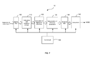
- the present invention also relates to a device, referenced 10 in figure 7 , able to implement the method described previously.
- the modules shown are functional units that may or may not correspond to physically distinguishable units.
- these modules or some of them can be grouped together in a single component, or constitute functions of the same software.
- some modules may be composed of separate physical entities.
- the device 10 comprises: a spatial filter 100 to smooth the video content of video frames at input to the device, a circuit for calculation and storage of histograms 110 to calculate and store histograms of video frames in compliance with step E1 of the method of the invention, a circuit for calculation of histogram difference 120 to determine, from histograms stored in the circuit 110 and for each video frame, a histogram difference in compliance with step E2 of the method of the invention, a first comparison circuit 130 to determine, from the histogram differences, a difference parameter in compliance with step E3 of the method of the invention, a temporal filter 140 to temporally filter the sequence of difference parameters generated by the circuit 130, a second comparison circuit 150 to compare the difference parameters with predetermined patterns to deliver mode information MODE and finally a control unit 160 to control the set of circuits 100 to 150.
- a spatial filter 100 to smooth the video content of video frames at input to the device
- a circuit for calculation and storage of histograms 110 to calculate and store histograms of video frames in compliance with step
Applications Claiming Priority (1)
| Application Number | Priority Date | Filing Date | Title |
|---|---|---|---|
| FR0858233A FR2939265A1 (fr) | 2008-12-03 | 2008-12-03 | Procede de detection de mode film ou mode camera |
Publications (2)
| Publication Number | Publication Date |
|---|---|
| EP2194714A1 true EP2194714A1 (fr) | 2010-06-09 |
| EP2194714B1 EP2194714B1 (fr) | 2018-01-10 |
Family
ID=40718878
Family Applications (1)
| Application Number | Title | Priority Date | Filing Date |
|---|---|---|---|
| EP09177296.2A Active EP2194714B1 (fr) | 2008-12-03 | 2009-11-27 | Procédé de détection du mode film ou du mode caméra |
Country Status (6)
| Country | Link |
|---|---|
| US (1) | US8351697B2 (fr) |
| EP (1) | EP2194714B1 (fr) |
| JP (1) | JP5547464B2 (fr) |
| KR (1) | KR101622363B1 (fr) |
| CN (1) | CN101754047B (fr) |
| FR (1) | FR2939265A1 (fr) |
Cited By (1)
| Publication number | Priority date | Publication date | Assignee | Title |
|---|---|---|---|---|
| CN103297740A (zh) * | 2013-05-29 | 2013-09-11 | 四川长虹电器股份有限公司 | 显示装置的卡顿现象消除方法 |
Families Citing this family (9)
| Publication number | Priority date | Publication date | Assignee | Title |
|---|---|---|---|---|
| JP2008294696A (ja) * | 2007-05-24 | 2008-12-04 | Sony Corp | 映像信号処理方法、映像信号処理方法のプログラム、映像信号処理方法のプログラムを記録した記録媒体及び映像信号処理装置 |
| KR101843902B1 (ko) * | 2010-06-25 | 2018-04-02 | 톰슨 라이센싱 | 높은 동적 범위 비디오를 톤 맵핑하기 위한 그래픽 사용자 인터페이스 |
| TWI414182B (zh) * | 2010-12-01 | 2013-11-01 | Novatek Microelectronics Corp | 多媒體裝置及其播放模式偵測方法 |
| KR20120105199A (ko) * | 2011-03-15 | 2012-09-25 | 엘지디스플레이 주식회사 | 다중 시청 가능한 입체영상 표시장치 및 그 구동방법 |
| CN102740107A (zh) * | 2011-04-11 | 2012-10-17 | 鸿富锦精密工业(深圳)有限公司 | 影像监控设备的破坏侦测系统及方法 |
| CN102158723B (zh) * | 2011-04-13 | 2012-07-04 | 上海文广科技(集团)有限公司 | 3d双投影仪自动同步方法及自动同步的3d播放系统 |
| CN104243887B (zh) * | 2014-09-10 | 2017-08-01 | 上海交通大学 | 一种基于不规则采样的电影模式检测方法和装置 |
| CN106488312B (zh) * | 2015-08-31 | 2019-04-30 | 展讯通信(上海)有限公司 | 视频源的检测方法及装置 |
| CN106650691A (zh) * | 2016-12-30 | 2017-05-10 | 北京旷视科技有限公司 | 图像处理方法和图像处理设备 |
Citations (4)
| Publication number | Priority date | Publication date | Assignee | Title |
|---|---|---|---|---|
| EP1100267A1 (fr) * | 1999-05-12 | 2001-05-16 | Matsushita Electric Industrial Co., Ltd. | Dispositif de detection de signaux video de telecinema |
| US20030185442A1 (en) * | 2002-03-29 | 2003-10-02 | Koninklijke Philips Electronics N.V. | Method and apparatus for detecting scene changes in video using a histogram of frame differences |
| US20040227852A1 (en) | 2003-03-05 | 2004-11-18 | Darren Neuman | Pulldown field detector |
| JP2008154169A (ja) | 2006-12-20 | 2008-07-03 | Fujitsu Ltd | 信号処理回路および信号処理装置 |
Family Cites Families (13)
| Publication number | Priority date | Publication date | Assignee | Title |
|---|---|---|---|---|
| US5166781A (en) * | 1991-05-10 | 1992-11-24 | Thomson Consumer Electronics, Inc. | Apparatus for identifying standard and non-standard video signals |
| JP3490490B2 (ja) * | 1994-01-28 | 2004-01-26 | 株式会社東芝 | パターン画像処理装置及び画像処理方法 |
| TW307971B (fr) * | 1994-03-31 | 1997-06-11 | Matsushita Electric Ind Co Ltd | |
| KR0137702B1 (ko) * | 1994-12-13 | 1998-05-15 | 양승택 | 필름모드 영상신호 검출장치 |
| JP2001012923A (ja) * | 1999-06-30 | 2001-01-19 | Toshiba Corp | パターン抽出方法、パターン抽出装置、微小異物形状測定方法、微小異物形状測定装置、ホール中央部の穴径測定方法、ホール中央部の穴径測定装置、ホール段差測定方法及びホール段差測定装置 |
| CA2330854A1 (fr) * | 2001-01-11 | 2002-07-11 | Jaldi Semiconductor Corp. | Systeme et methode pour detecter une source non video dans des signaux video |
| JP2004032234A (ja) * | 2002-06-25 | 2004-01-29 | Matsushita Electric Ind Co Ltd | 画像表示装置 |
| KR20050086876A (ko) * | 2002-11-26 | 2005-08-30 | 코닌클리케 필립스 일렉트로닉스 엔.브이. | 모션 시퀀스 패턴 검출 |
| US7075581B1 (en) * | 2003-06-03 | 2006-07-11 | Zoran Corporation | Interlaced-to-progressive scan conversion based on film source detection |
| US7277581B1 (en) * | 2003-08-19 | 2007-10-02 | Nvidia Corporation | Method for video format detection |
| US7643090B2 (en) * | 2003-12-30 | 2010-01-05 | The Nielsen Company (Us), Llc. | Methods and apparatus to distinguish a signal originating from a local device from a broadcast signal |
| JP2005285071A (ja) * | 2004-03-31 | 2005-10-13 | Sanyo Electric Co Ltd | 画像処理装置 |
| EP1592256B1 (fr) * | 2004-04-30 | 2009-06-17 | Panasonic Corporation | Correction d'information d'état d'image |
-
2008
- 2008-12-03 FR FR0858233A patent/FR2939265A1/fr active Pending
-
2009
- 2009-11-24 KR KR1020090114079A patent/KR101622363B1/ko active IP Right Grant
- 2009-11-27 EP EP09177296.2A patent/EP2194714B1/fr active Active
- 2009-12-03 JP JP2009275438A patent/JP5547464B2/ja active Active
- 2009-12-03 US US12/592,787 patent/US8351697B2/en active Active
- 2009-12-03 CN CN200910252679.2A patent/CN101754047B/zh active Active
Patent Citations (4)
| Publication number | Priority date | Publication date | Assignee | Title |
|---|---|---|---|---|
| EP1100267A1 (fr) * | 1999-05-12 | 2001-05-16 | Matsushita Electric Industrial Co., Ltd. | Dispositif de detection de signaux video de telecinema |
| US20030185442A1 (en) * | 2002-03-29 | 2003-10-02 | Koninklijke Philips Electronics N.V. | Method and apparatus for detecting scene changes in video using a histogram of frame differences |
| US20040227852A1 (en) | 2003-03-05 | 2004-11-18 | Darren Neuman | Pulldown field detector |
| JP2008154169A (ja) | 2006-12-20 | 2008-07-03 | Fujitsu Ltd | 信号処理回路および信号処理装置 |
Cited By (1)
| Publication number | Priority date | Publication date | Assignee | Title |
|---|---|---|---|---|
| CN103297740A (zh) * | 2013-05-29 | 2013-09-11 | 四川长虹电器股份有限公司 | 显示装置的卡顿现象消除方法 |
Also Published As
| Publication number | Publication date |
|---|---|
| EP2194714B1 (fr) | 2018-01-10 |
| JP5547464B2 (ja) | 2014-07-16 |
| CN101754047A (zh) | 2010-06-23 |
| KR20100063655A (ko) | 2010-06-11 |
| CN101754047B (zh) | 2014-08-06 |
| KR101622363B1 (ko) | 2016-05-19 |
| US8351697B2 (en) | 2013-01-08 |
| US20100246953A1 (en) | 2010-09-30 |
| FR2939265A1 (fr) | 2010-06-04 |
| JP2010136374A (ja) | 2010-06-17 |
Similar Documents
| Publication | Publication Date | Title |
|---|---|---|
| EP2194714A1 (fr) | Procédé de détection du mode film ou du mode caméra | |
| US8558772B2 (en) | Image display apparatus | |
| US20050249282A1 (en) | Film-mode detection in video sequences | |
| KR100914619B1 (ko) | 디인터레이싱 방법, 장치 및 시스템 | |
| US20020075400A1 (en) | Video restoring apparatus and method thereof | |
| DE3807751A1 (de) | Rauschverringerungsschaltung fuer videosignal mit halbbildspeicher | |
| US7460180B2 (en) | Method for false color suppression | |
| US7176982B2 (en) | Recursive noise reduction with still pixel detection | |
| KR101140442B1 (ko) | 이미지 상태 정보의 정정 방법, 움직임 보상 이미지 처리방법, 및 이미지 상태 정보 정정기 | |
| US20040233336A1 (en) | Still pixel detection using multiple windows and thresholds | |
| CN115829873A (zh) | 一种图像还原方法及处理系统 | |
| US20050243934A1 (en) | Processing auxiliary data of video sequences | |
| US20070211957A1 (en) | Image processing method and apparatus thereof | |
| CN100534205C (zh) | 抑制错误图像颜色的方法 | |
| JP4019503B2 (ja) | 映像信号処理装置及び映像信号処理方法 | |
| US20070002170A1 (en) | Video image conversion method for interlaced image to progressive image and system thereof | |
| JPH05292352A (ja) | ラインノイズ除去回路 | |
| JP2002158869A (ja) | 画像処理装置および画像表示装置、画像処理方法および画像表示方法 | |
| JPS60116291A (ja) | デイジタル信号記録再生装置 | |
| JPH04304082A (ja) | 画像信号変換装置 | |
| JPH1117985A (ja) | 画質補正回路 | |
| EP0492462A2 (fr) | Détecteur de forme d'ondes | |
| JPH02217083A (ja) | 動き検出回路 | |
| JP2001285864A (ja) | エラー修整装置および方法 | |
| JPH07336619A (ja) | テレビジョン受像機 |
Legal Events
| Date | Code | Title | Description |
|---|---|---|---|
| PUAI | Public reference made under article 153(3) epc to a published international application that has entered the european phase |
Free format text: ORIGINAL CODE: 0009012 |
|
| AK | Designated contracting states |
Kind code of ref document: A1 Designated state(s): AT BE BG CH CY CZ DE DK EE ES FI FR GB GR HR HU IE IS IT LI LT LU LV MC MK MT NL NO PL PT RO SE SI SK SM TR |
|
| AX | Request for extension of the european patent |
Extension state: AL BA RS |
|
| 17P | Request for examination filed |
Effective date: 20101118 |
|
| 17Q | First examination report despatched |
Effective date: 20110209 |
|
| GRAP | Despatch of communication of intention to grant a patent |
Free format text: ORIGINAL CODE: EPIDOSNIGR1 |
|
| RAP1 | Party data changed (applicant data changed or rights of an application transferred) |
Owner name: THOMSON LICENSING DTV |
|
| INTG | Intention to grant announced |
Effective date: 20170622 |
|
| RIN1 | Information on inventor provided before grant (corrected) |
Inventor name: KERVEC, JONATHAN Inventor name: GUERMOUD, HASSANE Inventor name: JOLLY, EMMANUEL |
|
| GRAS | Grant fee paid |
Free format text: ORIGINAL CODE: EPIDOSNIGR3 |
|
| GRAA | (expected) grant |
Free format text: ORIGINAL CODE: 0009210 |
|
| AK | Designated contracting states |
Kind code of ref document: B1 Designated state(s): AT BE BG CH CY CZ DE DK EE ES FI FR GB GR HR HU IE IS IT LI LT LU LV MC MK MT NL NO PL PT RO SE SI SK SM TR |
|
| REG | Reference to a national code |
Ref country code: GB Ref legal event code: FG4D |
|
| REG | Reference to a national code |
Ref country code: CH Ref legal event code: EP Ref country code: AT Ref legal event code: REF Ref document number: 963645 Country of ref document: AT Kind code of ref document: T Effective date: 20180115 |
|
| REG | Reference to a national code |
Ref country code: IE Ref legal event code: FG4D |
|
| REG | Reference to a national code |
Ref country code: DE Ref legal event code: R096 Ref document number: 602009050292 Country of ref document: DE |
|
| REG | Reference to a national code |
Ref country code: NL Ref legal event code: MP Effective date: 20180110 |
|
| REG | Reference to a national code |
Ref country code: DE Ref legal event code: R084 Ref document number: 602009050292 Country of ref document: DE |
|
| REG | Reference to a national code |
Ref country code: AT Ref legal event code: MK05 Ref document number: 963645 Country of ref document: AT Kind code of ref document: T Effective date: 20180110 |
|
| PG25 | Lapsed in a contracting state [announced via postgrant information from national office to epo] |
Ref country code: NL Free format text: LAPSE BECAUSE OF FAILURE TO SUBMIT A TRANSLATION OF THE DESCRIPTION OR TO PAY THE FEE WITHIN THE PRESCRIBED TIME-LIMIT Effective date: 20180110 |
|
| PG25 | Lapsed in a contracting state [announced via postgrant information from national office to epo] |
Ref country code: FI Free format text: LAPSE BECAUSE OF FAILURE TO SUBMIT A TRANSLATION OF THE DESCRIPTION OR TO PAY THE FEE WITHIN THE PRESCRIBED TIME-LIMIT Effective date: 20180110 Ref country code: NO Free format text: LAPSE BECAUSE OF FAILURE TO SUBMIT A TRANSLATION OF THE DESCRIPTION OR TO PAY THE FEE WITHIN THE PRESCRIBED TIME-LIMIT Effective date: 20180410 Ref country code: LT Free format text: LAPSE BECAUSE OF FAILURE TO SUBMIT A TRANSLATION OF THE DESCRIPTION OR TO PAY THE FEE WITHIN THE PRESCRIBED TIME-LIMIT Effective date: 20180110 Ref country code: HR Free format text: LAPSE BECAUSE OF FAILURE TO SUBMIT A TRANSLATION OF THE DESCRIPTION OR TO PAY THE FEE WITHIN THE PRESCRIBED TIME-LIMIT Effective date: 20180110 Ref country code: ES Free format text: LAPSE BECAUSE OF FAILURE TO SUBMIT A TRANSLATION OF THE DESCRIPTION OR TO PAY THE FEE WITHIN THE PRESCRIBED TIME-LIMIT Effective date: 20180110 Ref country code: CY Free format text: LAPSE BECAUSE OF FAILURE TO SUBMIT A TRANSLATION OF THE DESCRIPTION OR TO PAY THE FEE WITHIN THE PRESCRIBED TIME-LIMIT Effective date: 20180110 |
|
| PG25 | Lapsed in a contracting state [announced via postgrant information from national office to epo] |
Ref country code: LV Free format text: LAPSE BECAUSE OF FAILURE TO SUBMIT A TRANSLATION OF THE DESCRIPTION OR TO PAY THE FEE WITHIN THE PRESCRIBED TIME-LIMIT Effective date: 20180110 Ref country code: SE Free format text: LAPSE BECAUSE OF FAILURE TO SUBMIT A TRANSLATION OF THE DESCRIPTION OR TO PAY THE FEE WITHIN THE PRESCRIBED TIME-LIMIT Effective date: 20180110 Ref country code: GR Free format text: LAPSE BECAUSE OF FAILURE TO SUBMIT A TRANSLATION OF THE DESCRIPTION OR TO PAY THE FEE WITHIN THE PRESCRIBED TIME-LIMIT Effective date: 20180411 Ref country code: PL Free format text: LAPSE BECAUSE OF FAILURE TO SUBMIT A TRANSLATION OF THE DESCRIPTION OR TO PAY THE FEE WITHIN THE PRESCRIBED TIME-LIMIT Effective date: 20180110 Ref country code: IS Free format text: LAPSE BECAUSE OF FAILURE TO SUBMIT A TRANSLATION OF THE DESCRIPTION OR TO PAY THE FEE WITHIN THE PRESCRIBED TIME-LIMIT Effective date: 20180510 Ref country code: BG Free format text: LAPSE BECAUSE OF FAILURE TO SUBMIT A TRANSLATION OF THE DESCRIPTION OR TO PAY THE FEE WITHIN THE PRESCRIBED TIME-LIMIT Effective date: 20180410 Ref country code: AT Free format text: LAPSE BECAUSE OF FAILURE TO SUBMIT A TRANSLATION OF THE DESCRIPTION OR TO PAY THE FEE WITHIN THE PRESCRIBED TIME-LIMIT Effective date: 20180110 |
|
| REG | Reference to a national code |
Ref country code: DE Ref legal event code: R097 Ref document number: 602009050292 Country of ref document: DE |
|
| REG | Reference to a national code |
Ref country code: FR Ref legal event code: PLFP Year of fee payment: 10 |
|
| PG25 | Lapsed in a contracting state [announced via postgrant information from national office to epo] |
Ref country code: RO Free format text: LAPSE BECAUSE OF FAILURE TO SUBMIT A TRANSLATION OF THE DESCRIPTION OR TO PAY THE FEE WITHIN THE PRESCRIBED TIME-LIMIT Effective date: 20180110 Ref country code: IT Free format text: LAPSE BECAUSE OF FAILURE TO SUBMIT A TRANSLATION OF THE DESCRIPTION OR TO PAY THE FEE WITHIN THE PRESCRIBED TIME-LIMIT Effective date: 20180110 Ref country code: EE Free format text: LAPSE BECAUSE OF FAILURE TO SUBMIT A TRANSLATION OF THE DESCRIPTION OR TO PAY THE FEE WITHIN THE PRESCRIBED TIME-LIMIT Effective date: 20180110 |
|
| PLBE | No opposition filed within time limit |
Free format text: ORIGINAL CODE: 0009261 |
|
| STAA | Information on the status of an ep patent application or granted ep patent |
Free format text: STATUS: NO OPPOSITION FILED WITHIN TIME LIMIT |
|
| PG25 | Lapsed in a contracting state [announced via postgrant information from national office to epo] |
Ref country code: SK Free format text: LAPSE BECAUSE OF FAILURE TO SUBMIT A TRANSLATION OF THE DESCRIPTION OR TO PAY THE FEE WITHIN THE PRESCRIBED TIME-LIMIT Effective date: 20180110 Ref country code: CZ Free format text: LAPSE BECAUSE OF FAILURE TO SUBMIT A TRANSLATION OF THE DESCRIPTION OR TO PAY THE FEE WITHIN THE PRESCRIBED TIME-LIMIT Effective date: 20180110 Ref country code: DK Free format text: LAPSE BECAUSE OF FAILURE TO SUBMIT A TRANSLATION OF THE DESCRIPTION OR TO PAY THE FEE WITHIN THE PRESCRIBED TIME-LIMIT Effective date: 20180110 Ref country code: SM Free format text: LAPSE BECAUSE OF FAILURE TO SUBMIT A TRANSLATION OF THE DESCRIPTION OR TO PAY THE FEE WITHIN THE PRESCRIBED TIME-LIMIT Effective date: 20180110 |
|
| 26N | No opposition filed |
Effective date: 20181011 |
|
| PG25 | Lapsed in a contracting state [announced via postgrant information from national office to epo] |
Ref country code: SI Free format text: LAPSE BECAUSE OF FAILURE TO SUBMIT A TRANSLATION OF THE DESCRIPTION OR TO PAY THE FEE WITHIN THE PRESCRIBED TIME-LIMIT Effective date: 20180110 |
|
| REG | Reference to a national code |
Ref country code: DE Ref legal event code: R081 Ref document number: 602009050292 Country of ref document: DE Owner name: INTERDIGITAL MADISON PATENT HOLDINGS, FR Free format text: FORMER OWNER: THOMSON LICENSING DTV, LSSY-LES-MOULINEAUX, FR |
|
| REG | Reference to a national code |
Ref country code: CH Ref legal event code: PL |
|
| GBPC | Gb: european patent ceased through non-payment of renewal fee |
Effective date: 20181127 |
|
| PG25 | Lapsed in a contracting state [announced via postgrant information from national office to epo] |
Ref country code: LU Free format text: LAPSE BECAUSE OF NON-PAYMENT OF DUE FEES Effective date: 20181127 Ref country code: MC Free format text: LAPSE BECAUSE OF FAILURE TO SUBMIT A TRANSLATION OF THE DESCRIPTION OR TO PAY THE FEE WITHIN THE PRESCRIBED TIME-LIMIT Effective date: 20180110 |
|
| REG | Reference to a national code |
Ref country code: BE Ref legal event code: MM Effective date: 20181130 |
|
| REG | Reference to a national code |
Ref country code: IE Ref legal event code: MM4A |
|
| PG25 | Lapsed in a contracting state [announced via postgrant information from national office to epo] |
Ref country code: CH Free format text: LAPSE BECAUSE OF NON-PAYMENT OF DUE FEES Effective date: 20181130 Ref country code: LI Free format text: LAPSE BECAUSE OF NON-PAYMENT OF DUE FEES Effective date: 20181130 |
|
| PG25 | Lapsed in a contracting state [announced via postgrant information from national office to epo] |
Ref country code: IE Free format text: LAPSE BECAUSE OF NON-PAYMENT OF DUE FEES Effective date: 20181127 |
|
| PG25 | Lapsed in a contracting state [announced via postgrant information from national office to epo] |
Ref country code: BE Free format text: LAPSE BECAUSE OF NON-PAYMENT OF DUE FEES Effective date: 20181130 |
|
| PG25 | Lapsed in a contracting state [announced via postgrant information from national office to epo] |
Ref country code: GB Free format text: LAPSE BECAUSE OF NON-PAYMENT OF DUE FEES Effective date: 20181127 |
|
| PG25 | Lapsed in a contracting state [announced via postgrant information from national office to epo] |
Ref country code: MT Free format text: LAPSE BECAUSE OF NON-PAYMENT OF DUE FEES Effective date: 20181127 |
|
| PG25 | Lapsed in a contracting state [announced via postgrant information from national office to epo] |
Ref country code: TR Free format text: LAPSE BECAUSE OF FAILURE TO SUBMIT A TRANSLATION OF THE DESCRIPTION OR TO PAY THE FEE WITHIN THE PRESCRIBED TIME-LIMIT Effective date: 20180110 |
|
| PG25 | Lapsed in a contracting state [announced via postgrant information from national office to epo] |
Ref country code: PT Free format text: LAPSE BECAUSE OF FAILURE TO SUBMIT A TRANSLATION OF THE DESCRIPTION OR TO PAY THE FEE WITHIN THE PRESCRIBED TIME-LIMIT Effective date: 20180110 |
|
| PG25 | Lapsed in a contracting state [announced via postgrant information from national office to epo] |
Ref country code: MK Free format text: LAPSE BECAUSE OF NON-PAYMENT OF DUE FEES Effective date: 20180110 Ref country code: HU Free format text: LAPSE BECAUSE OF FAILURE TO SUBMIT A TRANSLATION OF THE DESCRIPTION OR TO PAY THE FEE WITHIN THE PRESCRIBED TIME-LIMIT; INVALID AB INITIO Effective date: 20091127 |
|
| PGFP | Annual fee paid to national office [announced via postgrant information from national office to epo] |
Ref country code: FR Payment date: 20221122 Year of fee payment: 14 Ref country code: DE Payment date: 20220527 Year of fee payment: 14 |
|
| P01 | Opt-out of the competence of the unified patent court (upc) registered |
Effective date: 20230514 |