EP2194253A2 - Saugrohreinrichtung - Google Patents
Saugrohreinrichtung Download PDFInfo
- Publication number
- EP2194253A2 EP2194253A2 EP09177837A EP09177837A EP2194253A2 EP 2194253 A2 EP2194253 A2 EP 2194253A2 EP 09177837 A EP09177837 A EP 09177837A EP 09177837 A EP09177837 A EP 09177837A EP 2194253 A2 EP2194253 A2 EP 2194253A2
- Authority
- EP
- European Patent Office
- Prior art keywords
- switching flap
- suction tube
- tube device
- switching
- flap
- Prior art date
- Legal status (The legal status is an assumption and is not a legal conclusion. Google has not performed a legal analysis and makes no representation as to the accuracy of the status listed.)
- Granted
Links
Images

Classifications
-
- F—MECHANICAL ENGINEERING; LIGHTING; HEATING; WEAPONS; BLASTING
- F02—COMBUSTION ENGINES; HOT-GAS OR COMBUSTION-PRODUCT ENGINE PLANTS
- F02B—INTERNAL-COMBUSTION PISTON ENGINES; COMBUSTION ENGINES IN GENERAL
- F02B27/00—Use of kinetic or wave energy of charge in induction systems, or of combustion residues in exhaust systems, for improving quantity of charge or for increasing removal of combustion residues
- F02B27/02—Use of kinetic or wave energy of charge in induction systems, or of combustion residues in exhaust systems, for improving quantity of charge or for increasing removal of combustion residues the systems having variable, i.e. adjustable, cross-sectional areas, chambers of variable volume, or like variable means
- F02B27/0205—Use of kinetic or wave energy of charge in induction systems, or of combustion residues in exhaust systems, for improving quantity of charge or for increasing removal of combustion residues the systems having variable, i.e. adjustable, cross-sectional areas, chambers of variable volume, or like variable means characterised by the charging effect
- F02B27/0215—Oscillating pipe charging, i.e. variable intake pipe length charging
-
- F—MECHANICAL ENGINEERING; LIGHTING; HEATING; WEAPONS; BLASTING
- F02—COMBUSTION ENGINES; HOT-GAS OR COMBUSTION-PRODUCT ENGINE PLANTS
- F02B—INTERNAL-COMBUSTION PISTON ENGINES; COMBUSTION ENGINES IN GENERAL
- F02B27/00—Use of kinetic or wave energy of charge in induction systems, or of combustion residues in exhaust systems, for improving quantity of charge or for increasing removal of combustion residues
- F02B27/02—Use of kinetic or wave energy of charge in induction systems, or of combustion residues in exhaust systems, for improving quantity of charge or for increasing removal of combustion residues the systems having variable, i.e. adjustable, cross-sectional areas, chambers of variable volume, or like variable means
- F02B27/0226—Use of kinetic or wave energy of charge in induction systems, or of combustion residues in exhaust systems, for improving quantity of charge or for increasing removal of combustion residues the systems having variable, i.e. adjustable, cross-sectional areas, chambers of variable volume, or like variable means characterised by the means generating the charging effect
- F02B27/0268—Valves
- F02B27/0273—Flap valves
-
- F—MECHANICAL ENGINEERING; LIGHTING; HEATING; WEAPONS; BLASTING
- F02—COMBUSTION ENGINES; HOT-GAS OR COMBUSTION-PRODUCT ENGINE PLANTS
- F02D—CONTROLLING COMBUSTION ENGINES
- F02D9/00—Controlling engines by throttling air or fuel-and-air induction conduits or exhaust conduits
- F02D9/08—Throttle valves specially adapted therefor; Arrangements of such valves in conduits
- F02D9/10—Throttle valves specially adapted therefor; Arrangements of such valves in conduits having pivotally-mounted flaps
- F02D9/1005—Details of the flap
- F02D9/101—Special flap shapes, ribs, bores or the like
- F02D9/1015—Details of the edge of the flap, e.g. for lowering flow noise or improving flow sealing in closed flap position
-
- F—MECHANICAL ENGINEERING; LIGHTING; HEATING; WEAPONS; BLASTING
- F02—COMBUSTION ENGINES; HOT-GAS OR COMBUSTION-PRODUCT ENGINE PLANTS
- F02D—CONTROLLING COMBUSTION ENGINES
- F02D9/00—Controlling engines by throttling air or fuel-and-air induction conduits or exhaust conduits
- F02D9/08—Throttle valves specially adapted therefor; Arrangements of such valves in conduits
- F02D9/10—Throttle valves specially adapted therefor; Arrangements of such valves in conduits having pivotally-mounted flaps
- F02D9/1005—Details of the flap
- F02D9/1025—Details of the flap the rotation axis of the flap being off-set from the flap center axis
- F02D9/103—Details of the flap the rotation axis of the flap being off-set from the flap center axis the rotation axis being located at an edge
-
- F—MECHANICAL ENGINEERING; LIGHTING; HEATING; WEAPONS; BLASTING
- F02—COMBUSTION ENGINES; HOT-GAS OR COMBUSTION-PRODUCT ENGINE PLANTS
- F02D—CONTROLLING COMBUSTION ENGINES
- F02D9/00—Controlling engines by throttling air or fuel-and-air induction conduits or exhaust conduits
- F02D9/08—Throttle valves specially adapted therefor; Arrangements of such valves in conduits
- F02D9/10—Throttle valves specially adapted therefor; Arrangements of such valves in conduits having pivotally-mounted flaps
- F02D9/109—Throttle valves specially adapted therefor; Arrangements of such valves in conduits having pivotally-mounted flaps having two or more flaps
- F02D9/1095—Rotating on a common axis, e.g. having a common shaft
-
- F—MECHANICAL ENGINEERING; LIGHTING; HEATING; WEAPONS; BLASTING
- F02—COMBUSTION ENGINES; HOT-GAS OR COMBUSTION-PRODUCT ENGINE PLANTS
- F02B—INTERNAL-COMBUSTION PISTON ENGINES; COMBUSTION ENGINES IN GENERAL
- F02B27/00—Use of kinetic or wave energy of charge in induction systems, or of combustion residues in exhaust systems, for improving quantity of charge or for increasing removal of combustion residues
- F02B27/02—Use of kinetic or wave energy of charge in induction systems, or of combustion residues in exhaust systems, for improving quantity of charge or for increasing removal of combustion residues the systems having variable, i.e. adjustable, cross-sectional areas, chambers of variable volume, or like variable means
- F02B27/0226—Use of kinetic or wave energy of charge in induction systems, or of combustion residues in exhaust systems, for improving quantity of charge or for increasing removal of combustion residues the systems having variable, i.e. adjustable, cross-sectional areas, chambers of variable volume, or like variable means characterised by the means generating the charging effect
- F02B27/0247—Plenum chambers; Resonance chambers or resonance pipes
- F02B27/0263—Plenum chambers; Resonance chambers or resonance pipes the plenum chamber and at least one of the intake ducts having a common wall, and the intake ducts wrap partially around the plenum chamber, i.e. snail-type
-
- Y—GENERAL TAGGING OF NEW TECHNOLOGICAL DEVELOPMENTS; GENERAL TAGGING OF CROSS-SECTIONAL TECHNOLOGIES SPANNING OVER SEVERAL SECTIONS OF THE IPC; TECHNICAL SUBJECTS COVERED BY FORMER USPC CROSS-REFERENCE ART COLLECTIONS [XRACs] AND DIGESTS
- Y02—TECHNOLOGIES OR APPLICATIONS FOR MITIGATION OR ADAPTATION AGAINST CLIMATE CHANGE
- Y02T—CLIMATE CHANGE MITIGATION TECHNOLOGIES RELATED TO TRANSPORTATION
- Y02T10/00—Road transport of goods or passengers
- Y02T10/10—Internal combustion engine [ICE] based vehicles
- Y02T10/12—Improving ICE efficiencies
Definitions
- the invention relates to a suction pipe device in the intake tract of an internal combustion engine according to the preamble of claim 1.
- a Saugrohrstrom for a multi-cylinder internal combustion engine which has in a housing a number of suction tubes corresponding to the cylinders, each of which is associated with a pivoting flap.
- the cross-section of the suction pipes can be variably adjusted via the pivoting flaps.
- the pivoting flaps are arranged on a common control shaft, which is rotatably mounted in the housing of the intake manifold. In a rotary adjusting movement of the actuating shaft, the pivoting flaps are pivoted between a closed and an open position.
- central flaps are in the open state almost at moment equilibrium, so that the flaps in the open state hold their position and the risk that the pivoting flaps get into vibration, is significantly reduced.
- centrically mounted pivoting flaps are in the flow and affect them in a negative way.
- the invention has for its object to provide with simple constructive measures a suction tube, in which the flow is impaired in the least possible extent by the pivoting flaps and prevents swinging of the pivoting flaps or at least reduced.
- the intake manifold or installation according to the invention is located in the intake tract of an internal combustion engine and serves to supply combustion air to the cylinders of the internal combustion engine.
- the intake manifold is preferably made of plastic and is manufactured in particular by plastic injection molding and is designed as a prefabricated module that can be used in the intake.
- the intake manifold comprises a plurality of suction pipes, which is associated with at least one adjustable switching flap for influencing the flow through the suction pipes.
- a vibration reduction element is provided according to the invention, which is arranged on the switching flap or a component connected to the switching flap and counteracts the vibrations of the switching flap. With the aid of the vibration reduction element, a swinging up of the switching flap is prevented or at least reduced, so that the flow through the suction tubes is not or not substantially impaired.
- the vibration reduction element is designed as a damping element which damps the vibration of the switching flap.
- viscous vibration dampers come into consideration, which counteract any oscillating movement of the switching flap.
- damper for example, a coupling of the switching flap with a damping material consisting of vibration reduction element, wherein the kinetic energy of the switching flap by the compression of the material the vibration reducing element is dissipated, or friction damper or the like.
- the damping element acts between the switching flap and a housing-fixed component, against which the switching flap exerts the adjusting movement.
- the at least one switching flap is located on a control shaft, which is adjustably mounted in the housing, in which case the damping element is expediently arranged on the control shaft or the damping effect exerts on the control shaft, in particular in the region of the bearing of the control shaft in the case.
- the damping element is advantageously designed so that a damping is effective only at relatively high-frequency vibrations, but not or only to a reduced extent in the adjusting movement, which executes the switching flap between their parking positions.
- the switching flap held on the control shaft exerts, in particular, a rotary pivoting movement, wherein in the context of the invention basically also a translational movement or a mixed translatory-rotary adjusting movement comes into consideration.
- the pivoting or rotational movement is realized by a rotatable mounting of the control shaft in the housing, which is to be pivoted by an actuator about the axis of rotation.
- the damping elements are accordingly designed as a rotary damper.
- the vibration reducing element is designed as an additional mass element which is fixedly connected to the switching flap or a component connected to the switching flap and exerts the same movement as the switching flap or the component connected to the switching flap.
- An increase in the mass moment of inertia of the switching flap or the switching flap actuating shaft system is achieved via the additional mass element, the increased mass moment of inertia precluding vibrational excitation in the high-frequency oscillatory region, so that the switching flap exerts no high-frequency oscillations or executes such oscillations only to a reduced extent.
- the increased mass moment of inertia is also contrary to the regular adjusting movement of the switching flap; However, this can be compensated either by an increased actuating force or a setting torque or by a slowed adjusting movement.
- the additional mass element is arranged according to a preferred embodiment at a distance from the axis of rotation of the switching flap or a component connected to the switching flap. Since the height of the mass moment of inertia depends quadratically on the distance to the axis of rotation, even relatively small mass elements on the switching flap can lead to a significant increase in the total mass moment of inertia.
- the additional mass element is designed as a flywheel, which is connected to the actuating shaft.
- the flywheel is a relatively large rotating mass, which must be accelerated at a rotational adjustment movement of the actuating shaft and counteracts high-frequency vibration excitations.
- the switching flap is eccentrically mounted in a preferred embodiment, ie outside its center, since such switching flaps do not affect the flow through the intake manifold in the open state. In principle, however, is also an application to symmetrically mounted switching flaps into consideration.
- Fig. 1 a section through a suction pipe, which is arranged in the intake of an internal combustion engine, with a suction pipe for supplying combustion air to a cylinder of the internal combustion engine, the suction pipe is associated with an additional pipe and in the mouth region the additional tube is arranged in the suction tube an eccentrically mounted switching flap,
- Fig. 2 a Fig. 1 corresponding representation, but the switching flap in a pivoted position
- FIG. 3 and 4 a further embodiment of a suction tube, which is analogous to the Figures 1 and 2 is constructed, but with a symmetrically mounted switching flap,
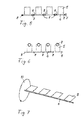
- Fig. 5 an illustration of a control shaft with four switching flaps arranged thereon, wherein damping elements are arranged in the region of the bearing points of the control shaft,
- Fig. 6 a further embodiment of a control shaft with four switching flaps disposed thereon, each carrying an additional mass element in its frontal region,
- Figure 7 a control shaft with switching flaps disposed thereon and an additional flywheel on the control shaft.
- a suction device 1 is shown, which is arranged in the intake tract of an internal combustion engine and via which the combustion air is to be supplied to the cylinders of an internal combustion engine.
- the suction pipe connection 1 comprises in a housing a suction pipe 2, which is to be attached via a flange 3 to the internal combustion engine.
- a switching flap 5 which is by means of a control shaft 6, the carrier of the switching flap 5, between the in Fig. 1 and Fig. 2 shown switching positions is to pivot.
- the actuating shaft 6 is to be rotated about an axis of rotation by means of an actuator.
- the switching flap 5 is mounted eccentrically, which is realized in that the adjusting shaft 6 extends outside the center through the switching flap 5.
- Fig. 1 is the switching flap 5 in the closed position in which the additional pipe 4 is separated via the switching flap 5 of the suction pipe 2.
- Fig. 2 the switching flap 5 is shown in an open position, in which the mouth region of the additional pipe 4 is opened into the suction pipe 2; at the same time an immediate flow passage is closed by an upstream portion of the suction pipe 2 in the section immediately adjacent to the flange 3.
- FIG. 3 and 4 is another suction tube 1 shown, the basic structure with the embodiment according to Fig. 1 and 2 is identical.
- the switching flap 5 in the mouth region of the additional tube 4 to the suction tube 2 is not eccentric, but mounted symmetrically or centrally on the control shaft 6, which is a rotational movement as a positioning movement can perform.
- the switching flap 5 in the in Fig. 3 illustrated intermediate position in which an inflow of combustion air is made possible both via the additional pipe 4 and over the upstream portion of the suction pipe 2, a lying in the flow path flow obstacle, which is adapted to affect the flow guidance through the intake manifold 1.
- Fig. 5 are a total of four switching flaps 5 arranged on the control shaft 6, which is mounted rotatably about its longitudinal axis in a plurality of axially spaced bearings 8 in the housing.
- a plurality of damping elements 7 are arranged on the control shaft 6, which are preferably located at the bearings 8.
- the damping elements 7 are viscous vibration dampers, which develop a speed-dependent damping effect.
- other damping elements come into consideration, such as friction damper or buffer elements, which consist of resilient material and cause damping by material compression.
- the damping elements 7 unfold their effect between the control shaft 6 and the housing, against which the actuating shaft executes its actuating movement.
- Fig. 6 the adjusting shaft 6 is shown with the four switching flaps 5 in a further embodiment, according to which a plurality of additional mass elements 9 are arranged on each switching flap 5.
- the additional mass elements 9 are each located in the region of the free end face on the position of the control shaft 6 facing away from the switching flaps 5 and increase in this way in a significant way the moment of inertia of each switching flap 5 and thus also the overall system consisting of the control shaft 6 and the total of four switching flaps. 5
- Each of the switching flaps 5 is equipped with such a mass element 9.
- control shaft 6 is provided with an additional mass element which is designed as a flywheel 10 and is arranged in the region of an end face of the control shaft 6.
- the flywheel 6 also causes a significant increase in the mass moment of inertia of the overall system, consisting of control shaft 6 and the switching flaps. 5
- flywheels may be provided at several actuators of the control shaft 6, for example, at both axial end faces of the control shaft. Also possible is an arrangement of a single flywheel in the central portion of the control shaft. In addition, a combination of flywheel and individual additional mass elements on the switching flaps is conceivable. Furthermore, a combination of damping elements, such as viscous vibration dampers as in Fig. 5 shown, with additional mass elements according to Fig. 6 or Fig. 7 possible.
Landscapes
- Engineering & Computer Science (AREA)
- Chemical & Material Sciences (AREA)
- Combustion & Propulsion (AREA)
- Mechanical Engineering (AREA)
- General Engineering & Computer Science (AREA)
- Characterised By The Charging Evacuation (AREA)
Abstract
Description
- Die Erfindung bezieht sich auf eine Saugrohreinrichtung im Ansaugtrakt einer Brennkraftmaschine nach dem Oberbegriff des Anspruches 1.
- Aus der
DE 42 28 334 A1 ist eine Saugrohranlage für eine Mehrzylinder-Brennkraftmaschine bekannt, die in einem Gehäuse eine den Zylindern entsprechende Anzahl an Saugrohren aufweist, denen jeweils eine Schwenkklappe zugeordnet ist. Über die Schwenkklappen ist der Querschnitt der Saugrohre variabel einzustellen. Die Schwenkklappen sind an einer gemeinsamen Stellwelle angeordnet, die drehbar im Gehäuse der Saugrohranlage gelagert ist. Bei einer rotatorischen Stellbewegung der Stellwelle werden die Schwenkklappen zwischen einer geschlossenen und einer geöffneten Position verschwenkt. - Grundsätzlich kommt bei derartigen Schwenkklappen entweder eine exzentrische oder eine zentrische Lagerung in Betracht. Bei der exzentrischen Lagerung verläuft die Stellwelle außerhalb des Mittelpunktes der Schwenkklappe, bei der zentrischen Lagerung ist die Stellwelle durch den Mittelpunkt geführt. Die exzentrische Lagerung hat den Vorteil, dass im geöffneten Klappenzustand die Strömung durch die Schwenkklappe nur sehr gering beeinträchtigt wird. Allerdings können bei exzentrisch gelagerten Klappen verhältnismäßig hochfrequente, von der aktuellen Motordrehzahl abhängige Schwingungen in den Klappen entstehen, die die Strömung und das Drehmoment ungünstig beeinflussen.
- Die zentrischen Klappen befinden sich im geöffneten Zustand nahezu im Momentengleichgewicht, so dass die Klappen im geöffneten Zustand ihre Position halten und die Gefahr, dass die Schwenkklappen in Schwingungen geraten, erheblich reduziert ist. Andererseits liegen zentrisch gelagerte Schwenkklappen in der Strömung und beeinflussen diese in negativer Weise.
- Der Erfindung liegt die Aufgabe zugrunde, mit einfachen konstruktiven Maßnahmen eine Saugrohreinrichtung anzugeben, bei der die Strömung in geringstmöglichem Maße durch die Schwenkklappen beeinträchtigt wird und ein Aufschwingen der Schwenkklappen verhindert oder zumindest reduziert ist.
- Diese Aufgabe wird erfindungsgemäß mit den Merkmalen des Anspruches 1 gelöst. Die Unteransprüche geben zweckmäßige Weiterbildungen an.
- Die erfindungsgemäße Saugrohreinrichtung bzw. -anlage befindet sich im Ansaugtrakt einer Brennkraftmaschine und dient zur Zufuhr von Verbrennungsluft zu den Zylindern der Brennkraftmaschine. Die Saugrohreinrichtung besteht vorzugsweise aus Kunststoff und wird insbesondere im Kunststoff-Spritzgussverfahren hergestellt und ist als vorgefertigtes Modul ausgebildet, das in den Ansaugtrakt eingesetzt werden kann.
- Die Saugrohreinrichtung umfasst eine Mehrzahl von Saugrohren, denen mindestens eine verstellbare Schaltklappe zur Beeinflussung der Strömung durch die Saugrohre zugeordnet ist. Um ein Aufschwingen der Schaltklappe insbesondere durch die vorbeiströmende Verbrennungsluft zu verhindern, die die Schaltklappe zu Schwingungen anregt, ist erfindungsgemäß ein Schwingungsreduzierungselement vorgesehen, welches an der Schaltklappe oder einem mit der Schaltklappe verbundenen Bauteil angeordnet ist und den Schwingungen der Schaltklappe entgegenwirkt. Mithilfe des Schwingungsreduzierungselementes wird ein Aufschwingen der Schaltklappe unterbunden oder zumindest reduziert, so dass auch die Strömung durch die Saugrohre nicht oder nicht im wesentlichen Maße beeinträchtigt wird.
- Die Schwingungsreduzierung mithilfe des Schwingungsreduzierungselementes kann auf verschiedene Weisen erzielt werden. Gemäß einer ersten vorteilhaften Ausführung ist vorgesehen, dass das Schwingungsreduzierungselement als ein Dämpfungselement ausgebildet ist, welches die Schwingung der Schaltklappe dämpft. Hier kommen insbesondere viskose Schwingungsdämpfer in Betracht, die jeder Schwingbewegung der Schaltklappe entgegenwirken. Möglich sind aber auch sonstige Dämpferarten, beispielsweise ein Koppeln der Schaltklappe mit einem aus dämpfendem Material bestehenden Schwingungsreduzierungselement, bei dem die Bewegungsenergie der Schaltklappe durch die Kompression des Materials des Schwingungsreduzierungselementes dissipiert wird, oder Reibungsdämpfer oder dergleichen.
- Das Dämpfungselement wirkt zwischen der Schaltklappe und einem gehäusefesten Bauteil, gegenüber dem die Schaltklappe die Stellbewegung ausübt. Gemäß einer bevorzugten Ausführung befindet sich die mindestens eine Schaltklappe auf einer Stellwelle, die im Gehäuse verstellbar gelagert ist, wobei in diesem Fall das Dämpfungselement zweckmäßigerweise an der Stellwelle angeordnet ist bzw. die dämpfende Wirkung auf die Stellwelle ausübt, insbesondere im Bereich der Lagerung der Stellwelle im Gehäuse.
- Das Dämpfungselement ist vorteilhafterweise so ausgelegt, dass eine Dämpfung nur bei verhältnismäßig hochfrequenten Schwingungen wirksam wird, jedoch nicht oder nur in reduziertem Maße bei der Stellbewegung, welche die Schaltklappe zwischen ihren Stellpositionen ausführt.
- Die an der Stellwelle gehaltene Schaltklappe übt insbesondere eine rotatorische Schwenkbewegung aus, wobei im Rahmen der Erfindung grundsätzlich auch eine translatorische Bewegung oder eine gemischt translatorisch-rotatorische Stellbewegung in Betracht kommt. Die Schwenk- bzw. Drehbewegung wird durch eine drehbare Lagerung der Stellwelle im Gehäuse realisiert, die von einem Aktuator um die Rotationsachse zu verschwenken ist. Die Dämpfungselemente sind dementsprechend als Drehdämpfer ausgeführt.
- Gemäß einer weiteren erfindungsgemäßen Ausführung ist das Schwingungsreduzierungselement als ein Zusatzmassenelement ausgebildet, welches fest mit der Schaltklappe oder einem mit der Schaltklappe verbundenen Bauteil verbunden ist und die gleiche Bewegung wie die Schaltklappe bzw. das mit der Schaltklappe verbundene Bauteil ausübt. Über das Zusatzmassenelement wird eine Erhöhung des Massenträgheitsmomentes der Schaltklappe bzw. des Schaltklappen-Stellwellen-Systems erreicht, wobei das erhöhte Massenträgheitsmoment einer Schwingungsanregung im hochfrequenten Schwingungsbereich entgegensteht, so dass die Schaltklappe keine hochfrequenten Schwingungen ausübt bzw. nur in reduziertem Maße derartige Schwingungen ausführt. Zwar steht das erhöhte Massenträgheitsmoment auch der regulären Stellbewegung der Schaltklappe entgegen; dies kann jedoch entweder durch eine erhöhte Stellkraft bzw. ein Stellmoment oder durch eine verlangsamte Stellbewegung kompensiert werden.
- Das Zusatzmassenelement ist gemäß einer bevorzugten Ausführung mit Abstand zur Drehachse an der Schaltklappe oder einem mit der Schaltklappe verbundenen Bauteil angeordnet. Da die Höhe des Massenträgheitsmomentes quadratisch vom Abstand zur Drehachse abhängt, können bereits verhältnismäßig geringe Massenelemente an der Schaltklappe zu einer signifikanten Erhöhung des Gesamtmassenträgheitsmomentes führen.
- Gemäß einer weiteren vorteilhaften Ausführung ist das Zusatzmassenelement als ein Schwungrad ausgebildet, das mit der Stellwelle verbunden ist. Das Schwungrad stellt eine verhältnismäßig große Drehmasse dar, die bei einer rotatorischen Stellbewegung der Stellwelle mit beschleunigt werden muss und hochfrequenten Schwingungsanregungen entgegenwirkt.
- Gegebenenfalls kommt eine Kombination von Dämpfungselement und Zusatzmassenelement in Betracht, wodurch eine besondere effektive Schwingungsdämpfung bzw. -reduzierung gegeben ist.
- Die Schaltklappe ist in bevorzugter Ausführung exzentrisch gelagert, also außerhalb ihres Mittelpunktes, da derartige Schaltklappen im geöffneten Zustand die Strömung durch das Saugrohr nicht beeinträchtigen. Grundsätzlich kommt aber auch eine Anwendung auf symmetrisch gelagerte Schaltklappen in Betracht.
- Weitere Vorteile und zweckmäßige Ausführungen sind den weiteren Ansprüchen, der Figurenbeschreibung und den Zeichnungen zu entnehmen. Es zeigen:
-
Fig. 1 einen Schnitt durch eine Saugrohreinrichtung, welche im Ansaugtrakt einer Brennkraftmaschine angeordnet ist, mit einem Saugrohr zur Zufuhr von Verbrennungsluft zu einem Zylinder der Brennkraftmaschine, wobei dem Saugrohr ein Zusatzrohr zugeordnet ist und im Mündungsbereich des Zusatzrohres in das Saugrohr eine exzentrisch gelagerte Schaltklappe angeordnet ist, -
Fig. 2 eineFig. 1 entsprechende Darstellung, jedoch die Schaltklappe in einer verschwenkten Position, -
Fig. 3 und 4 ein weiteres Ausführungsbeispiel einer Saugrohreinrichtung, das analog zu denFiguren 1 und 2 aufgebaut ist, jedoch mit einer symmetrisch gelagerten Schaltklappe, -
Fig. 5 eine Darstellung einer Stellwelle mit vier daran angeordneten Schaltklappen, wobei im Bereich der Lagerstellen der Stellwelle Dämpfungselemente angeordnet sind, -
Fig. 6 ein weiteres Ausführungsbeispiel einer Stellwelle mit vier daran angeordneten Schaltklappen, die in ihrem stirnseitigen Bereich jeweils ein Zusatzmassenelement tragen, -
Fig.7 eine Stellwelle mit daran angeordneten Schaltklappen und einem zusätzlichen Schwungrad an der Stellwelle. - In den Figuren sind gleiche Bauteile mit gleichen Bezugszeichen versehen.
- In den
Figuren 1 und 2 ist eine Saugeinrichtung 1 dargestellt, die im Ansaugtrakt einer Brennkraftmaschine angeordnet ist und über die den Zylindern einer Brennkraftmaschine Verbrennungsluft zuzuführen ist. Die Saugrohrverbindung 1 umfasst in einem Gehäuse ein Saugrohr 2, welches über einen Flansch 3 an der Brennkraftmaschine zu befestigen ist. In der Saugrohreinrichtung 1 befindet sich eine Schaltklappe 5, die mittels einer Stellwelle 6, die Träger der Schaltklappe 5 ist, zwischen den inFig. 1 und Fig. 2 dargestellten Schaltpositionen zu verschwenken ist. Die Stellwelle 6 ist mithilfe eines Aktuators um eine Rotationsachse zu verdrehen. Die Schaltklappe 5 ist exzentrisch gelagert, was dadurch realisiert ist, dass die Stellwelle 6 außerhalb des Mittelpunktes durch die Schaltklappe 5 verläuft. - In der Saugrohreinrichtung 1 befindet sich ein Zusatzrohr 4, welches in das Saugrohr 2 mündet, wobei die Schaltklappe 5 im Mündungsbereich des Zusatzrohrs 4 in das Saugrohr 2 angeordnet ist. In
Fig. 1 befindet sich die Schaltklappe 5 in der geschlossenen Position, in der das Zusatzrohr 4 über die Schaltklappe 5 von dem Saugrohr 2 getrennt ist. InFig. 2 ist die Schaltklappe 5 in einer geöffneten Position dargestellt, in der der Mündungsbereich des Zusatzrohrs 4 in das Saugrohr 2 geöffnet ist; zugleich ist ein unmittelbarer Strömungsübertritt von einem stromauf liegenden Abschnitt des Saugrohres 2 in den Abschnitt unmittelbar benachbart zum Flansch 3 verschlossen. - In
Fig. 3 und 4 ist eine weitere Saugrohreinrichtung 1 dargestellt, deren Grundaufbau mit dem Ausführungsbeispiel gemäßFig. 1 und 2 identisch ist. Die Schaltklappe 5 im Mündungsbereich des Zusatzrohres 4 zum Saugrohr 2 ist jedoch nicht exzentrisch, sondern symmetrisch bzw. zentrisch an der Stellwelle 6 gelagert, die als Stellbewegung eine Rotationsbewegung ausführen kann. Allerdings stellt die Schaltklappe 5 in der inFig. 3 dargestellten Zwischenposition, in welcher eine Zuströmung von Verbrennungsluft sowohl über das Zusatzrohr 4 als auch über den stromauf gelegenen Abschnitt des Saugrohres 2 ermöglicht ist, ein im Strömungsweg liegendes Strömungshindernis dar, welches geeignet ist, die Strömungsführung durch die Saugrohreinrichtung 1 zu beeinträchtigen. - Im Ausführungsbeispiel gemäß
Fig. 5 sind insgesamt vier Schaltklappen 5 an der Stellwelle 6 angeordnet, die um ihre Längsachse verdrehbar in mehreren axial beabstandeten Lagerstellen 8 im Gehäuse gelagert ist. Um hochfrequente Schwingungen zu dämpfen, sind an der Stellwelle 6 mehrere Dämpfungselemente 7 angeordnet, welche sich vorzugsweise an den Lagerstellen 8 befinden. Bei den Dämpfungselementen 7 handelt es sich um viskose Schwingungsdämpfer, die eine geschwindigkeitsabhängige Dämpfungswirkung entfalten. Gegebenenfalls kommen aber auch andere Dämpfungselemente in Betracht, beispielsweise Reibungsdämpfer oder Pufferelemente, welche aus nachgiebigem Material bestehen und eine Dämpfung durch Materialkompression bewirken. Die Dämpfungselemente 7 entfalten ihre Wirkung zwischen der Stellwelle 6 und dem Gehäuse, gegenüber dem die Stellwelle ihre Stellbewegung ausführt. - In
Fig. 6 ist die Stellwelle 6 mit den vier Schaltklappen 5 in einer weiteren Ausführung dargestellt, gemäß der eine Mehrzahl von Zusatzmassenelementen 9 an jeder Schaltklappe 5 angeordnet sind. Die Zusatzmassenelemente 9 befinden sich jeweils im Bereich der freien Stirnseite auf der der Stellwelle 6 abgewandten Position an den Schaltklappen 5 und erhöhen auf diese Weise in signifikanter Weise das Trägheitsmoment jeder Schaltklappe 5 und damit auch des Gesamtsystems, bestehend aus der Stellwelle 6 und den insgesamt vier Schaltklappen 5. Jede der Schaltklappen 5 ist mit einem derartigen Massenelement 9 ausgestattet. - Im Ausführungsbeispiel gemäß
Fig. 7 ist die Stellwelle 6 mit einem Zusatzmassenelement versehen, welches als Schwungrad 10 ausgebildet ist und im Bereich einer Stirnseite der Stellwelle 6 angeordnet ist. Das Schwungrad 6 bewirkt ebenfalls eine signifikante Erhöhung des Massenträgheitsmomentes des Gesamtsystems, bestehend aus Stellwelle 6 und den Schaltklappen 5. - Gegebenenfalls können an mehreren Steller der Stellwelle 6 derartige Schwungräder vorgesehen sein, beispielsweise an beiden axialen Stirnseiten der Stellwelle. Möglich ist auch eine Anordnung eines einzelnen Schwungrades im mittleren Abschnitt der Stellwelle. Außerdem ist auch eine Kombination von Schwungrad und einzelnen Zusatzmassenelementen an den Schaltklappen denkbar. Des Weiteren ist eine Kombination von Dämpfungselementen, beispielsweise viskosen Schwingungsdämpfern wie in
Fig. 5 dargestellt, mit Zusatzmassenelementen gemäßFig. 6 oder Fig. 7 möglich.
Claims (11)
- Saugrohreinrichtung im Ansaugtrakt einer Brennkraftmaschine, mit einer Mehrzahl von Saugrohren (2), denen mindestens eine verstellbare Schaltklappe (5) zur Beeinflussung der Strömung durch die Saugrohre (2) zugeordnet ist, dadurch gekennzeichnet, dass an der Schaltklappe (5) oder an einem mit der Schaltklappe (5) verbundenen Bauteil (6) mindestens ein Schwingungsreduzierungselement (7, 9, 10) angeordnet ist, das Schwingungen der Schaltklappe (5) entgegenwirkt.
- Saugrohreinrichtung nach Anspruch 1, dadurch gekennzeichnet, dass das Schwingungsreduzierungselement als Dämpfungselement (7) ausgeführt ist, welches die Schwingbewegung der Schaltklappe (5) dämpft.
- Saugrohreinrichtung nach Anspruch 2, dadurch gekennzeichnet, dass das Dämpfungselement (7) als viskoser Schwingungsdämpfer ausgeführt ist.
- Saugrohreinrichtung nach einem der Ansprüche 1 bis 4, dadurch gekennzeichnet, dass das Schwingungsreduzierungselement als ein Zusatzmassenelement (9) ausgeführt ist, welches fest mit der Schaltklappe (5) oder mit einem mit der Schaltklappe (5) verbundenen Bauteil (6) verbunden ist und die gleiche Bewegung wie die Schaltklappe (5) bzw. das mit der Schaltklappe (5) verbundene Bauteil ausübt.
- Saugrohreinrichtung nach Anspruch 4, dadurch gekennzeichnet, dass das Zusatzmassenelement (9) mit Abstand zur Drehachse an der Schaltklappe (5) angeordnet ist.
- Saugrohreinrichtung nach einem der Ansprüche 1 bis 5, dadurch gekennzeichnet, dass das Schwingungsreduzierungselement (7, 10) an einer Stellwelle (6) angeordnet ist, an der die Schaltklappe (5) gehalten ist.
- Saugrohreinrichtung nach Anspruch 6, dadurch gekennzeichnet, dass an der Stellwelle (6) mehrere Schwingungsreduzierungselemente (7, 10) angeordnet sind.
- Saugrohreinrichtung nach Anspruch 6 oder 7, dadurch gekennzeichnet, dass an der Stellwelle (6) mehrere Schaltklappen (5) angeordnet sind, denen jeweils ein Schwingungsreduzierungselement (7, 9) zugeordnet ist.
- Saugrohreinrichtung nach Anspruch 4 oder 5 und einem der Ansprüche 6 bis 8, dadurch gekennzeichnet, dass das Zusatzmassenelement (9) als ein mit der Stellwelle (6) verbundenes Schwungrad (10) ausgeführt ist.
- Saugrohreinrichtung nach einem der Ansprüche 1 bis 9, dadurch gekennzeichnet, dass die Schaltklappe (5) schwenkbar gelagert ist.
- Saugrohreinrichtung nach Anspruch 10, dadurch gekennzeichnet, dass die Schaltklappe (5) exzentrisch gelagert ist.
Applications Claiming Priority (1)
| Application Number | Priority Date | Filing Date | Title |
|---|---|---|---|
| DE102008060235A DE102008060235A1 (de) | 2008-12-04 | 2008-12-04 | Saugrohreinrichtung |
Publications (3)
| Publication Number | Publication Date |
|---|---|
| EP2194253A2 true EP2194253A2 (de) | 2010-06-09 |
| EP2194253A3 EP2194253A3 (de) | 2012-08-29 |
| EP2194253B1 EP2194253B1 (de) | 2013-11-20 |
Family
ID=41491509
Family Applications (1)
| Application Number | Title | Priority Date | Filing Date |
|---|---|---|---|
| EP09177837.3A Active EP2194253B1 (de) | 2008-12-04 | 2009-12-03 | Saugrohreinrichtung |
Country Status (2)
| Country | Link |
|---|---|
| EP (1) | EP2194253B1 (de) |
| DE (1) | DE102008060235A1 (de) |
Citations (2)
| Publication number | Priority date | Publication date | Assignee | Title |
|---|---|---|---|---|
| DE4228334A1 (de) | 1992-08-26 | 1994-03-03 | Audi Ag | Saugrohranlage für eine Mehrzylinder-Brennkraftmaschine |
| US20070017469A1 (en) | 2005-07-20 | 2007-01-25 | Siemens Vdo Automotive Inc. | Intake manifold with low chatter shaft system |
Family Cites Families (3)
| Publication number | Priority date | Publication date | Assignee | Title |
|---|---|---|---|---|
| DE4243134A1 (de) * | 1992-12-19 | 1994-06-23 | Daimler Benz Ag | Verfahren und Betätigungsvorrichtung zur Dämpfung der Öffnungsbewegung einer Drosselklappe in einer Ansaugleitung einer Brennkraftmaschine |
| DE19714311B4 (de) * | 1997-04-08 | 2005-11-17 | Pierburg Gmbh | Luftansaugkanalsystem für Brennkraftmaschinen |
| US7011072B2 (en) * | 2004-04-13 | 2006-03-14 | Delphi Technologies, Inc. | Shaft noise damper |
-
2008
- 2008-12-04 DE DE102008060235A patent/DE102008060235A1/de not_active Withdrawn
-
2009
- 2009-12-03 EP EP09177837.3A patent/EP2194253B1/de active Active
Patent Citations (2)
| Publication number | Priority date | Publication date | Assignee | Title |
|---|---|---|---|---|
| DE4228334A1 (de) | 1992-08-26 | 1994-03-03 | Audi Ag | Saugrohranlage für eine Mehrzylinder-Brennkraftmaschine |
| US20070017469A1 (en) | 2005-07-20 | 2007-01-25 | Siemens Vdo Automotive Inc. | Intake manifold with low chatter shaft system |
Also Published As
| Publication number | Publication date |
|---|---|
| EP2194253B1 (de) | 2013-11-20 |
| DE102008060235A1 (de) | 2010-06-10 |
| EP2194253A3 (de) | 2012-08-29 |
Similar Documents
| Publication | Publication Date | Title |
|---|---|---|
| EP0726388B1 (de) | Ansaugsystem | |
| EP2577004B1 (de) | Hydraulisch betätigte nockenwellenverstellvorrichtung | |
| DE102015211891B4 (de) | Frequenzabhängige Dämpfventilanordnung | |
| DE10137828B4 (de) | In einem Einlasskanal einer Kolbenbrennkraftmaschine angeordnete Zusatzsteuerventileinrichtung | |
| DE102008045492A1 (de) | Federdämpfungssystem mit mindestens zwei Gasfedern | |
| WO2015003921A1 (de) | Vorrichtung zur betätigung der wastegateklappe eines abgasturboladers | |
| WO2012072186A1 (de) | Lageranordnung für eine welle eines turbinenrades | |
| EP0451499B1 (de) | Regelbarer Schwingungsdämpfer für Kraftfahrzeuge | |
| DE102012015536B4 (de) | Abgasanlage für eine Brennkraftmaschine | |
| EP2881634A1 (de) | Klappenanordnung für ein Stellglied, insbesondere für ein Abgasventil eines Verbrennungsmotors | |
| EP0731878B1 (de) | Vorrichtung zur regelung der leerlaufdrehzahl einer brennkraftmaschine | |
| DE10204768B4 (de) | Drallverstellbarer Einlasskanal mit zumindest einer in Längsrichtung verlaufenden Trennwand | |
| EP2194253B1 (de) | Saugrohreinrichtung | |
| EP1170483A2 (de) | Luftansaugvorrichtung für eine Brennkraftmaschine | |
| DE10319403B4 (de) | Klappenvorrichtung | |
| DE10331391A1 (de) | Schwungrad | |
| WO2018197262A1 (de) | Regelvorrichtung für eine verbrennungskraftmaschine | |
| WO1997021025A2 (de) | Luftansaugvorrichtung für eine brennkraftmaschine | |
| DE102004009502B3 (de) | Klappensystem, insbesondere zur Änderung der Strömungsverhältnisse an Einlassventilen | |
| EP2133538B1 (de) | Gasführendes Drehventil mit Torsionsfeder | |
| EP1279811B1 (de) | Verschlussorgan, insbesondere für einen Saugkanal einer Brennkraftmaschine | |
| EP4278111A1 (de) | Drehschwingungsdämpfer | |
| DE202004020030U1 (de) | Saugrohranlage für eine Mehrzylinderbrennkraftmaschine | |
| DE2911489A1 (de) | Drosseleinrichtung fuer ein treibstoff-einspritzsystem einer brennkraftmaschine | |
| DE10334475B4 (de) | Klappensystem für eine Verbrennungskraftmaschine |
Legal Events
| Date | Code | Title | Description |
|---|---|---|---|
| PUAI | Public reference made under article 153(3) epc to a published international application that has entered the european phase |
Free format text: ORIGINAL CODE: 0009012 |
|
| AK | Designated contracting states |
Kind code of ref document: A2 Designated state(s): AT BE BG CH CY CZ DE DK EE ES FI FR GB GR HR HU IE IS IT LI LT LU LV MC MK MT NL NO PL PT RO SE SI SK SM TR |
|
| PUAL | Search report despatched |
Free format text: ORIGINAL CODE: 0009013 |
|
| AK | Designated contracting states |
Kind code of ref document: A3 Designated state(s): AT BE BG CH CY CZ DE DK EE ES FI FR GB GR HR HU IE IS IT LI LT LU LV MC MK MT NL NO PL PT RO SE SI SK SM TR |
|
| AX | Request for extension of the european patent |
Extension state: AL BA RS |
|
| RIC1 | Information provided on ipc code assigned before grant |
Ipc: F02B 27/02 20060101AFI20120725BHEP Ipc: F02D 9/10 20060101ALI20120725BHEP |
|
| 17P | Request for examination filed |
Effective date: 20130220 |
|
| GRAP | Despatch of communication of intention to grant a patent |
Free format text: ORIGINAL CODE: EPIDOSNIGR1 |
|
| INTG | Intention to grant announced |
Effective date: 20130610 |
|
| GRAS | Grant fee paid |
Free format text: ORIGINAL CODE: EPIDOSNIGR3 |
|
| GRAA | (expected) grant |
Free format text: ORIGINAL CODE: 0009210 |
|
| AK | Designated contracting states |
Kind code of ref document: B1 Designated state(s): AT BE BG CH CY CZ DE DK EE ES FI FR GB GR HR HU IE IS IT LI LT LU LV MC MK MT NL NO PL PT RO SE SI SK SM TR |
|
| REG | Reference to a national code |
Ref country code: GB Ref legal event code: FG4D Free format text: NOT ENGLISH |
|
| REG | Reference to a national code |
Ref country code: CH Ref legal event code: EP |
|
| REG | Reference to a national code |
Ref country code: AT Ref legal event code: REF Ref document number: 641796 Country of ref document: AT Kind code of ref document: T Effective date: 20131215 |
|
| REG | Reference to a national code |
Ref country code: IE Ref legal event code: FG4D Free format text: LANGUAGE OF EP DOCUMENT: GERMAN |
|
| REG | Reference to a national code |
Ref country code: DE Ref legal event code: R096 Ref document number: 502009008372 Country of ref document: DE Effective date: 20140116 |
|
| REG | Reference to a national code |
Ref country code: NL Ref legal event code: VDEP Effective date: 20131120 |
|
| REG | Reference to a national code |
Ref country code: LT Ref legal event code: MG4D |
|
| PG25 | Lapsed in a contracting state [announced via postgrant information from national office to epo] |
Ref country code: FI Free format text: LAPSE BECAUSE OF FAILURE TO SUBMIT A TRANSLATION OF THE DESCRIPTION OR TO PAY THE FEE WITHIN THE PRESCRIBED TIME-LIMIT Effective date: 20131120 Ref country code: NO Free format text: LAPSE BECAUSE OF FAILURE TO SUBMIT A TRANSLATION OF THE DESCRIPTION OR TO PAY THE FEE WITHIN THE PRESCRIBED TIME-LIMIT Effective date: 20140220 Ref country code: IS Free format text: LAPSE BECAUSE OF FAILURE TO SUBMIT A TRANSLATION OF THE DESCRIPTION OR TO PAY THE FEE WITHIN THE PRESCRIBED TIME-LIMIT Effective date: 20140320 Ref country code: NL Free format text: LAPSE BECAUSE OF FAILURE TO SUBMIT A TRANSLATION OF THE DESCRIPTION OR TO PAY THE FEE WITHIN THE PRESCRIBED TIME-LIMIT Effective date: 20131120 Ref country code: LT Free format text: LAPSE BECAUSE OF FAILURE TO SUBMIT A TRANSLATION OF THE DESCRIPTION OR TO PAY THE FEE WITHIN THE PRESCRIBED TIME-LIMIT Effective date: 20131120 Ref country code: HR Free format text: LAPSE BECAUSE OF FAILURE TO SUBMIT A TRANSLATION OF THE DESCRIPTION OR TO PAY THE FEE WITHIN THE PRESCRIBED TIME-LIMIT Effective date: 20131120 Ref country code: SE Free format text: LAPSE BECAUSE OF FAILURE TO SUBMIT A TRANSLATION OF THE DESCRIPTION OR TO PAY THE FEE WITHIN THE PRESCRIBED TIME-LIMIT Effective date: 20131120 |
|
| PG25 | Lapsed in a contracting state [announced via postgrant information from national office to epo] |
Ref country code: LV Free format text: LAPSE BECAUSE OF FAILURE TO SUBMIT A TRANSLATION OF THE DESCRIPTION OR TO PAY THE FEE WITHIN THE PRESCRIBED TIME-LIMIT Effective date: 20131120 Ref country code: ES Free format text: LAPSE BECAUSE OF FAILURE TO SUBMIT A TRANSLATION OF THE DESCRIPTION OR TO PAY THE FEE WITHIN THE PRESCRIBED TIME-LIMIT Effective date: 20131120 |
|
| BERE | Be: lapsed |
Owner name: MANN + HUMMEL G.M.B.H. Effective date: 20131231 |
|
| PG25 | Lapsed in a contracting state [announced via postgrant information from national office to epo] |
Ref country code: PT Free format text: LAPSE BECAUSE OF FAILURE TO SUBMIT A TRANSLATION OF THE DESCRIPTION OR TO PAY THE FEE WITHIN THE PRESCRIBED TIME-LIMIT Effective date: 20140320 |
|
| PG25 | Lapsed in a contracting state [announced via postgrant information from national office to epo] |
Ref country code: EE Free format text: LAPSE BECAUSE OF FAILURE TO SUBMIT A TRANSLATION OF THE DESCRIPTION OR TO PAY THE FEE WITHIN THE PRESCRIBED TIME-LIMIT Effective date: 20131120 |
|
| REG | Reference to a national code |
Ref country code: CH Ref legal event code: PL |
|
| REG | Reference to a national code |
Ref country code: DE Ref legal event code: R097 Ref document number: 502009008372 Country of ref document: DE |
|
| PG25 | Lapsed in a contracting state [announced via postgrant information from national office to epo] |
Ref country code: PL Free format text: LAPSE BECAUSE OF FAILURE TO SUBMIT A TRANSLATION OF THE DESCRIPTION OR TO PAY THE FEE WITHIN THE PRESCRIBED TIME-LIMIT Effective date: 20131120 Ref country code: RO Free format text: LAPSE BECAUSE OF FAILURE TO SUBMIT A TRANSLATION OF THE DESCRIPTION OR TO PAY THE FEE WITHIN THE PRESCRIBED TIME-LIMIT Effective date: 20131120 Ref country code: SK Free format text: LAPSE BECAUSE OF FAILURE TO SUBMIT A TRANSLATION OF THE DESCRIPTION OR TO PAY THE FEE WITHIN THE PRESCRIBED TIME-LIMIT Effective date: 20131120 Ref country code: CZ Free format text: LAPSE BECAUSE OF FAILURE TO SUBMIT A TRANSLATION OF THE DESCRIPTION OR TO PAY THE FEE WITHIN THE PRESCRIBED TIME-LIMIT Effective date: 20131120 Ref country code: MC Free format text: LAPSE BECAUSE OF FAILURE TO SUBMIT A TRANSLATION OF THE DESCRIPTION OR TO PAY THE FEE WITHIN THE PRESCRIBED TIME-LIMIT Effective date: 20131120 |
|
| REG | Reference to a national code |
Ref country code: IE Ref legal event code: MM4A |
|
| PLBE | No opposition filed within time limit |
Free format text: ORIGINAL CODE: 0009261 |
|
| REG | Reference to a national code |
Ref country code: FR Ref legal event code: ST Effective date: 20140829 |
|
| STAA | Information on the status of an ep patent application or granted ep patent |
Free format text: STATUS: NO OPPOSITION FILED WITHIN TIME LIMIT |
|
| PG25 | Lapsed in a contracting state [announced via postgrant information from national office to epo] |
Ref country code: DK Free format text: LAPSE BECAUSE OF FAILURE TO SUBMIT A TRANSLATION OF THE DESCRIPTION OR TO PAY THE FEE WITHIN THE PRESCRIBED TIME-LIMIT Effective date: 20131120 |
|
| 26N | No opposition filed |
Effective date: 20140821 |
|
| GBPC | Gb: european patent ceased through non-payment of renewal fee |
Effective date: 20140220 |
|
| PG25 | Lapsed in a contracting state [announced via postgrant information from national office to epo] |
Ref country code: BE Free format text: LAPSE BECAUSE OF NON-PAYMENT OF DUE FEES Effective date: 20131231 Ref country code: CH Free format text: LAPSE BECAUSE OF NON-PAYMENT OF DUE FEES Effective date: 20131231 Ref country code: IE Free format text: LAPSE BECAUSE OF NON-PAYMENT OF DUE FEES Effective date: 20131203 Ref country code: LI Free format text: LAPSE BECAUSE OF NON-PAYMENT OF DUE FEES Effective date: 20131231 |
|
| PG25 | Lapsed in a contracting state [announced via postgrant information from national office to epo] |
Ref country code: FR Free format text: LAPSE BECAUSE OF NON-PAYMENT OF DUE FEES Effective date: 20140120 |
|
| REG | Reference to a national code |
Ref country code: DE Ref legal event code: R097 Ref document number: 502009008372 Country of ref document: DE Effective date: 20140821 |
|
| PG25 | Lapsed in a contracting state [announced via postgrant information from national office to epo] |
Ref country code: GB Free format text: LAPSE BECAUSE OF NON-PAYMENT OF DUE FEES Effective date: 20140220 |
|
| PG25 | Lapsed in a contracting state [announced via postgrant information from national office to epo] |
Ref country code: SI Free format text: LAPSE BECAUSE OF FAILURE TO SUBMIT A TRANSLATION OF THE DESCRIPTION OR TO PAY THE FEE WITHIN THE PRESCRIBED TIME-LIMIT Effective date: 20131120 |
|
| PG25 | Lapsed in a contracting state [announced via postgrant information from national office to epo] |
Ref country code: SM Free format text: LAPSE BECAUSE OF FAILURE TO SUBMIT A TRANSLATION OF THE DESCRIPTION OR TO PAY THE FEE WITHIN THE PRESCRIBED TIME-LIMIT Effective date: 20131120 |
|
| PG25 | Lapsed in a contracting state [announced via postgrant information from national office to epo] |
Ref country code: TR Free format text: LAPSE BECAUSE OF FAILURE TO SUBMIT A TRANSLATION OF THE DESCRIPTION OR TO PAY THE FEE WITHIN THE PRESCRIBED TIME-LIMIT Effective date: 20131120 Ref country code: CY Free format text: LAPSE BECAUSE OF FAILURE TO SUBMIT A TRANSLATION OF THE DESCRIPTION OR TO PAY THE FEE WITHIN THE PRESCRIBED TIME-LIMIT Effective date: 20131120 |
|
| PG25 | Lapsed in a contracting state [announced via postgrant information from national office to epo] |
Ref country code: BG Free format text: LAPSE BECAUSE OF FAILURE TO SUBMIT A TRANSLATION OF THE DESCRIPTION OR TO PAY THE FEE WITHIN THE PRESCRIBED TIME-LIMIT Effective date: 20131120 Ref country code: LU Free format text: LAPSE BECAUSE OF NON-PAYMENT OF DUE FEES Effective date: 20131203 Ref country code: MK Free format text: LAPSE BECAUSE OF FAILURE TO SUBMIT A TRANSLATION OF THE DESCRIPTION OR TO PAY THE FEE WITHIN THE PRESCRIBED TIME-LIMIT Effective date: 20131120 Ref country code: HU Free format text: LAPSE BECAUSE OF FAILURE TO SUBMIT A TRANSLATION OF THE DESCRIPTION OR TO PAY THE FEE WITHIN THE PRESCRIBED TIME-LIMIT; INVALID AB INITIO Effective date: 20091203 |
|
| PG25 | Lapsed in a contracting state [announced via postgrant information from national office to epo] |
Ref country code: MT Free format text: LAPSE BECAUSE OF FAILURE TO SUBMIT A TRANSLATION OF THE DESCRIPTION OR TO PAY THE FEE WITHIN THE PRESCRIBED TIME-LIMIT Effective date: 20131120 Ref country code: IT Free format text: LAPSE BECAUSE OF FAILURE TO SUBMIT A TRANSLATION OF THE DESCRIPTION OR TO PAY THE FEE WITHIN THE PRESCRIBED TIME-LIMIT Effective date: 20131120 Ref country code: GR Free format text: LAPSE BECAUSE OF NON-PAYMENT OF DUE FEES Effective date: 20131120 |
|
| REG | Reference to a national code |
Ref country code: AT Ref legal event code: MM01 Ref document number: 641796 Country of ref document: AT Kind code of ref document: T Effective date: 20141203 |
|
| PG25 | Lapsed in a contracting state [announced via postgrant information from national office to epo] |
Ref country code: AT Free format text: LAPSE BECAUSE OF NON-PAYMENT OF DUE FEES Effective date: 20141203 |
|
| PG25 | Lapsed in a contracting state [announced via postgrant information from national office to epo] |
Ref country code: GR Free format text: LAPSE BECAUSE OF FAILURE TO SUBMIT A TRANSLATION OF THE DESCRIPTION OR TO PAY THE FEE WITHIN THE PRESCRIBED TIME-LIMIT Effective date: 20140221 |
|
| REG | Reference to a national code |
Ref country code: DE Ref legal event code: R081 Ref document number: 502009008372 Country of ref document: DE Owner name: MANN+HUMMEL GMBH, DE Free format text: FORMER OWNER: MANN + HUMMEL GMBH, 71638 LUDWIGSBURG, DE |
|
| REG | Reference to a national code |
Ref country code: DE Ref legal event code: R081 Ref document number: 502009008372 Country of ref document: DE Owner name: MOLDTECS-01-2022 GMBH, DE Free format text: FORMER OWNER: MANN+HUMMEL GMBH, 71636 LUDWIGSBURG, DE |
|
| P01 | Opt-out of the competence of the unified patent court (upc) registered |
Effective date: 20240220 |
|
| PGFP | Annual fee paid to national office [announced via postgrant information from national office to epo] |
Ref country code: DE Payment date: 20251211 Year of fee payment: 17 |