EP2194207B1 - Holding device for the glass pane of a balustrade railing - Google Patents
Holding device for the glass pane of a balustrade railing Download PDFInfo
- Publication number
- EP2194207B1 EP2194207B1 EP08021182A EP08021182A EP2194207B1 EP 2194207 B1 EP2194207 B1 EP 2194207B1 EP 08021182 A EP08021182 A EP 08021182A EP 08021182 A EP08021182 A EP 08021182A EP 2194207 B1 EP2194207 B1 EP 2194207B1
- Authority
- EP
- European Patent Office
- Prior art keywords
- rail
- holding
- holding device
- box
- accordance
- Prior art date
- Legal status (The legal status is an assumption and is not a legal conclusion. Google has not performed a legal analysis and makes no representation as to the accuracy of the status listed.)
- Active
Links
- 239000011521 glass Substances 0.000 title claims description 14
- 239000002184 metal Substances 0.000 claims description 3
- 239000000853 adhesive Substances 0.000 description 2
- 230000001070 adhesive effect Effects 0.000 description 2
- 238000004519 manufacturing process Methods 0.000 description 2
- 239000005336 safety glass Substances 0.000 description 2
- 239000002313 adhesive film Substances 0.000 description 1
- 230000015572 biosynthetic process Effects 0.000 description 1
- 238000009435 building construction Methods 0.000 description 1
- 230000001447 compensatory effect Effects 0.000 description 1
- 230000001419 dependent effect Effects 0.000 description 1
- 238000011161 development Methods 0.000 description 1
- 230000018109 developmental process Effects 0.000 description 1
- 238000005755 formation reaction Methods 0.000 description 1
- 239000000463 material Substances 0.000 description 1
- 238000000034 method Methods 0.000 description 1
- 125000006850 spacer group Chemical group 0.000 description 1
- 239000000725 suspension Substances 0.000 description 1
Images


Classifications
-
- E—FIXED CONSTRUCTIONS
- E04—BUILDING
- E04F—FINISHING WORK ON BUILDINGS, e.g. STAIRS, FLOORS
- E04F11/00—Stairways, ramps, or like structures; Balustrades; Handrails
- E04F11/18—Balustrades; Handrails
- E04F11/181—Balustrades
- E04F11/1851—Filling panels, e.g. concrete, sheet metal panels
Definitions
- the invention relates to a holding device, by which one or more a balustrade forming glass sheets is supported on a wall or ceiling according to the preamble of claim 1.
- Such fixtures have been developed by the Applicant in the recent past; For example, such a holding device from the DE 103 38 816 B3 be removed.
- the glass panes forming the balustrade are inserted in a U-profile rail and are fixed there by means of an adhesive and spacers.
- a U-shaped designed shoulder bag is formed, which is hooked into a nose, which is integrally formed on a base profile.
- the basic profile is fixed to the ceiling and extends over the entire length of the parapet parapet.
- the bag and the molded on the base profile retaining lug take as a floating bearing horizontally acting forces, especially between the horizontally extending leg of the bag and the free end of the retaining lug in the assembled state, an air gap is provided.
- the vertical weight forces caused by the railing parapet that is to say the glass panes, are supported on the underside of the support rail by the base profile, because there is provided a detent designed as a fixed bearing, by which the U-profile rail is supported in the vertical and horizontal directions.
- the adjusting screws pass through a fixing plate, which is positively connected to the underside of the U-profile rail.
- a fixing plate which is positively connected to the underside of the U-profile rail.
- the basic profile has a complicated structural design. Namely, the basic profile is to be manufactured, for example, as an extruded profile in order to provide a contact surface extending over the entire length of the parapet parapet for the U-profile rail. In some buildings and applications, however, has been found that the structurally complex design of the basic profile after the DE 103 38 818 B3 not absolutely necessary.
- a clamping screw is provided, which is screwed to a in the box rail and a frictionally held in this nut and the other by means of the integrally formed on the clamping screw head on the outside of the support rail. Consequently, the support rail is supported by means of adjusting and clamping screws on the box rail;
- a strip or individual holding blocks can be molded to the upwardly projecting end face of the retaining plate to the building construction of the building to adapt the suspension of the support rail to the support plate to these circumstances.
- FIG. 1 is a holding device 1zu refer, is supported by a constructed of two sheets of glass 2 parapet railing 3 between two walls 4 on a ceiling 5.
- the selected representation is a schematic illustration for such balustrade parapets 3.
- the structural design of the holding device 1 and the different design variants and applications are shown in FIGS. 2 to 7. Identical components are provided with identical reference numbers.
- the holding device 1 consists of a U-shaped support rail 7, in which the two glass sheets 2 are inserted.
- the support rail 7 may also be designed as a L-shaped receiving body or as a plate.
- the two glass sheets 2 are firmly connected to one another via an adhesive film 6 arranged between them, so that a safety glass is produced.
- the safety glass so at least one of the two glass panes 2, is fixedly connected to the support rail 7, for example via an adhesive 8.
- mechanical connections for example by means of fastening screws, which pass through the glass sheets 2 and are supported on the support rail 7, can be used for the provision of a parapet parapet 3.
- the fixation of the two glass panes 2 with the support rail 7 takes place at the factory, so that they are delivered pre-assembled as a unit.
- a holding plate 9 made of metal by means of fastening screws 10 is attached.
- the holding plate 9 projects beyond the bottom formed by the ceiling 5, so that the free end 9 'of the holding plate 9, which protrudes from the ceiling 5, can be used as a retaining lug or retaining web for a molded onto the mounting rail 7 shoulder bag 25.
- the U-shaped designed shoulder bag 25, which is integrally formed on a support plate facing leg of the support rail 7, is used exclusively to support in the assembled state, the horizontally acting forces on the support plate 9 in the form of a floating bearing.
- an air gap 30 is provided between the horizontally extending leg of the shoulder bag 25 and the free end face of the holding plate 9.
- the balancing body 26 may be made of metal or of a hard material, such as plastic.
- the distance in the horizontal direction between the two inner surfaces of the shoulder bag 25 and the two outer surfaces of the support plate 9 can be compensated by the Ausreteskörpem 26; Namely, the width of the holding plate 9 may vary or have waves over its length.
- Such a compensatory measure causes the support rail 7 is tilted, that is inclined from the vertical in the direction of the support plate 9 and is applied to this linear.
- this pre-assembly condition is not desired for the parapet parapet 3; rather, the parapet parapet 3 should run vertically, ie exactly vertically.
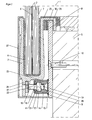
- a box rail 11 is provided in the lower region of the support rail 7, which via a support member 12, which in the illustrated embodiment of Figures 2 and 3 is formed as a box-shaped rail 14 is fixed to the holding plate 9.
- the rail 14 is secured by means of two opposing and mutually parallel welds 15 on the support plate 9 and is perpendicular from this.
- the top of the rail 14 forms a support surface 23 on which the underside of the support rail 7 flies in the mounted state and is thus supported in the vertical direction.
- a set screw 16 and a clamping screw 34 is used, which run perpendicular to the holding plate 9 and the head 16 'and 34' non-positively or positively connected to the support rail 7, as will be explained in more detail below are.
- the adjusting screw 16 engages through a slot-like or round opening 22 incorporated in the rail 14 and two through bores 18 and 19 incorporated in the box rail 11.
- the opening 22 and the two through bores 18 and 19 therefore run in alignment with one another in the mounted state.
- a rectangular recess 20 is incorporated into the interior of the box rail 11, into which a nut 21 is inserted, so that the threaded bore of the nut 21 is aligned with the opening 22 and the two through holes 18 and 19. Consequently, the free end of the adjusting screw 16 can first be screwed through the opening 22 and the through hole 18 into the threaded bore of the nut 21. Since the through hole 19 is aligned with the threaded bore of the nut 21, the free end of the screw can dip into this through hole 19, so that the rail from the box 11 and the rail 14 protruding part of the screw 16 is variably adjustable by the screw 16 is moved in the direction of the holding plate 9 or away.
- the head 16 'of the adjusting screw 16 is inserted into a U-shaped receiving pocket 24, which is integrally formed on the underside of the support rail 7. Consequently, it is the adjusting screw 16 frictionally connected in the horizontal direction with the support rail 7, so that by the screw 16 horizontal forces on the support rail 7 are transferable.
- a change in length of the adjusting screw 16 therefore causes the inclination of the support rail 7 relative to the support plate 9 and thus the cover 5 and the vertical can be changed, in dependence on the desired inclination.
- FIG. 3 can be seen that laterally next to the screw 16 a clamping screw 34 is screwed into the box rail 11.
- the clamping screw 34 serves as an additional definition of the support rail 7, so that a bearing is formed by the support surface 23 and the clamping of the support rail 7 by means of the screws 16 and the clamping screw 34, because in the mounted state are vertically and horizontally acting forces and their torques through which the support rail 7 is loaded, received by this design of the bearing and reliably supported.
- the support rail 7 can be covered to provide a privacy.
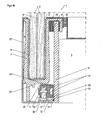
- FIGS. 4a and 4b a second embodiment of the holding device 1 is shown.
- the support member 12 is configured as a continuous bar 13 which is attached via the weld 15 on the holding plate .9.
- the bar 13 forms together with the holding plate 9 a right angle.
- a plurality of openings 22 are incorporated, in which the fixing screws 17 are inserted.
- the box rail 11 is placed on the surface of the retaining strip 13, ie between this and the underside of the support rail 7, the box rail 11 is placed.
- the incorporated in the box rail 11 through holes 18 and 19 are now facing the bar 13, so that in the through holes 18 and 19 are aligned with a machined into the bar 13 bore 28 and the fixing screw 17 can be inserted through this.
- the recess 20 is provided, into which the nut 21 is inserted for receiving the fixing screw 17. Consequently, the box rail 11 is held by the nut 21 and screwed into this fixing screw 17 on the bar 13 stationary.
- the adjusting screws 16 and the clamping screw 34 receiving through holes 18 and 19 extend perpendicular to the fixing screws 19 associated through holes 18 and 19, so that the head 16 'of the adjusting screw 16 and the head 34' of the clamping screw 34 formed on the support rail 7 Receiving pocket 25 facing and inserted into this.
- the holding device can also be used to support a balustrade for a staircase.
- the support rail 7 rests on the top of the rail 14, which is connected via the welds 15 with the support plate 9.
- the adjusting screw 16 engages in the interior of the box rail 11 and is supported there by means of the nut 21.
Description
Die Erfindung bezieht sich auf eine Haltevorrichtung, durch die eine oder mehrere eine Geländerbrüstung bildende Glasscheiben an einer Wand oder Decke abgestützt ist nach dem Oberbegriff des Patentanspruches 1.The invention relates to a holding device, by which one or more a balustrade forming glass sheets is supported on a wall or ceiling according to the preamble of
Solche Haltevorrichtungen sind von dem Patentanmelder in der jüngeren Vergangenheit entwickelt worden; beispielsweise kann eine solche Haltevorrichtung aus der
Das Grundprofil ist an der Decke befestigt und erstreckt sich über die gesamte Länge der Geländerbrüstung. Die Einhängetasche und die an dem Grundprofil angeformte Haltenase nehmen als Loslager horizontal wirkende Kräfte auf, zumal zwischen dem horizontal verlaufenden Schenkel der Einhängetasche und dem freien Ende der Haltenase im montierten Zustand ein Luftspalt vorgesehen ist.The basic profile is fixed to the ceiling and extends over the entire length of the parapet parapet. The bag and the molded on the base profile retaining lug take as a floating bearing horizontally acting forces, especially between the horizontally extending leg of the bag and the free end of the retaining lug in the assembled state, an air gap is provided.
Die vertikalen von der Geländerbrüstung, also den Glasscheiben hervorgerufenen Gewichtskräften werden an der Unterseite der Trageschiene durch das Grundprofil abgestützt, denn dort ist eine als Festlager ausgebildete Arretierung vorgesehen, durch die die U-Profilschiene in vertikaler und horizontaler Richtung abgestützt ist.The vertical weight forces caused by the railing parapet, that is to say the glass panes, are supported on the underside of the support rail by the base profile, because there is provided a detent designed as a fixed bearing, by which the U-profile rail is supported in the vertical and horizontal directions.
Zur lotrechten Einstellung der U-Profilschiene und damit der in dieser angeordneten Glasscheiben sind eine Vielzahl von Stellschrauben vorgesehen, die in eine Gewindebohrung, die in dem Festlager des Grundprofiles eingearbeitet ist, eingedreht sind.For vertical adjustment of the U-rail and thus arranged in this glass panes a plurality of screws are provided which are screwed into a threaded hole which is incorporated in the fixed bearing of the basic profile.
Die Stellschrauben durchgreifen eine Fixierplatte, die formschlüssig mit der Unterseite der U-Profilschiene verbunden ist. Beim Verdrehen der Stellschrauben werden horizontal wirkende Kräfte auf die U-Profilschiene übertragen, um diese in ihrer Neigung gegenüber dem Grundprofil und der Decke zu verändern, so dass die Neigung der Glasscheiben und der U-Profilschiene eingestellt werden kann.The adjusting screws pass through a fixing plate, which is positively connected to the underside of the U-profile rail. When turning the screws horizontally acting forces are transmitted to the U-profile rail to change their inclination relative to the base profile and the ceiling, so that the inclination of the glass sheets and the U-profile rail can be adjusted.
Derartige Haltevorrichtungen haben sich in der Praxis zwar bewährt, sind jedoch oftmals in ihrer Herstellung kostenintensiv, denn das Grundprofil weist eine komplizierte konstruktive Ausgestaltung auf. Das Grundprofil ist nämlich beispielsweise als Strangpressprofil zu fertigen, um eine sich über die gesamte Länge der Geländerbrüstung erstreckende Auflagefläche für die U-Profilschiene zur Verfügung zu stellen. Bei einigen Bauwerken und Anwendungen hat sich allerdings herausgestellt, dass die konstruktiv aufwendige Ausgestaltung des Grundprofils nach der
Es ist daher Aufgabe der Erfindung, eine Haltevorrichtung der eingangs genannten Gattung derart weiterzubilden, dass eine zuverlässige Abstützung der Geländerbrüstung an der Wand oder Decke bereitgestellt ist, deren Herstellungskosten minimiert sind.It is therefore an object of the invention to provide a holding device of the type mentioned in such a way that a reliable support of the balustrade parapet is provided on the wall or ceiling, the production costs are minimized.
Diese Aufgabe wird durch die Merkmale des kennzeichnenden Teils von Patentanspruch 1 gelöst.This object is solved by the features of the characterizing part of
Weitere vorteilhafte Weiterbildungen der Erfindung ergeben sich aus den Unteransprüchen.Further advantageous developments of the invention will become apparent from the dependent claims.
Dadurch, dass die Stellschraube nunmehr in einem als Einzelbauteil ausgebildeten Kastenschiene abgestützt ist und die Kastenschiene über ein Stützelement mit der Halteplatte verbunden ist, ist die konstruktive Ausgestaltung der Halteplatte, die unmittelbar an der Wand oder Decke befestigt ist, auf einfache Art und Weise herstellbar. Komplizierte und damit teure Anformungen, um die Stellschraube fixieren zu können, durch die die Neigung der als U-Profilschiene ausgebildeten Trageschiene eingestellt wird, entfallen somit.The fact that the screw is now supported in a trained as a single component box rail and the box rail is connected via a support member to the support plate, the structural design of the support plate which is attached directly to the wall or ceiling, in a simple manner. Complicated and thus expensive formations in order to fix the set screw, by which the inclination of the trained as a U-rail support rail is set, thus eliminating.
Seitlich neben jeder Stellschraube ist eine Einspannschraube vorgesehen, die zum einen in die Kastenschiene und einer in dieser kraftschlüssig gehaltenen Mutter eingedreht ist und die zum anderen mittels des an der Einspannschraube angeformten Kopfes auf der Außenseite der Trageschiene anliegt. Folglich wird die Tragschiene mittels der Stell- und Einspannschrauben an der Kastenschiene abgestützt; durch diese mechanische Fixierungsart können horizontal verlaufende Kräfte und deren Drehmomente, die auf die Geländerbrüstung einwirken, aufgenommen werden.Laterally next to each screw, a clamping screw is provided, which is screwed to a in the box rail and a frictionally held in this nut and the other by means of the integrally formed on the clamping screw head on the outside of the support rail. Consequently, the support rail is supported by means of adjusting and clamping screws on the box rail; By means of this mechanical fixation method, horizontally extending forces and their torques acting on the balustrade of the parapet can be absorbed.
Des Weiteren kann an die Baugegebenheit des Bauwerkes eine Leiste oder einzelne Halteklötze an die nach oben abstehende Stirnseite der Halteplatte angeformt werden, um die Einhängung der Trageschiene an der Halteplatte an diese Gegebenenheiten anzupassen.Furthermore, a strip or individual holding blocks can be molded to the upwardly projecting end face of the retaining plate to the building construction of the building to adapt the suspension of the support rail to the support plate to these circumstances.
Darüber hinaus kann während der Montage entschieden werden, an welchen Positionen die Trageschiene an der Halteplatte über die Stell- und Einspannschrauben abgestützt wird, denn die Kastenschienen können auch bereichsweise mit der Halteplatte verbunden werden, so dass diese nicht über die gesamte Länge der Trageschiene verlaufen müssen.In addition, it can be decided during assembly, at which positions the support rail is supported on the support plate via the adjusting and clamping screws, because the box rails can also be partially connected to the support plate, so that they do not have to extend over the entire length of the support rail ,
In der Zeichnung sind zwei Ausführungsbeispiele einer erfindungsgemäßen Haltevorrichtung dargestellt, die nachfolgend näher erläutert werden. Im Einzelnen zeigt:
Figur 1- eine Haltevorrichtung zur Abstützung einer Geländerbrüstung zwischen zwei Wänden und an einer Decke, in Vorderansicht,
Figur 2- ein erstes Ausführungsbeispiel der Haltevorrichtung gemäß
Figur 1 Figur 3- die Haltevorrichtung gemäß
Figur 2 - Figur 4a
- ein zweites Ausführungsbeispiel einer Haltevorrichtung, in perspektivischer Ansicht,
- Figur 4b
- die Haltevorrichtung gemäß
Figur 4a entlang der Schnittlinie IVb-IVb, Figur 5- eine andere Anwendung für die Haltevorrichtung gemäß
Figur 2 Figur 6- die Haltevorrichtung gemäß
Figur 5
- FIG. 1
- a holding device for supporting a balustrade between two walls and on a ceiling, in front view,
- FIG. 2
- a first embodiment of the holding device according to
FIG. 1 along the section line II-II, - FIG. 3
- the holding device according to
FIG. 2 along the section line III-III, - FIG. 4a
- A second embodiment of a holding device, in perspective view,
- FIG. 4b
- the holding device according to
FIG. 4a along the section line IVb-IVb, - FIG. 5
- another application for the holding device according to
FIG. 2 , by a staircase parapet is attached to a staircase, in perspective view and - FIG. 6
- the holding device according to
FIG. 5 along the section line VI-VI.
Aus
In
Die Fixierung der beiden Glasscheiben 2 mit der Trageschiene 7 erfolgt werksseitig, so dass diese bereits vormontiert als Baueinheit ausgeliefert werden.The fixation of the two
Zur Montage der Geländerbrüstung 3 ist es erforderlich, dass an der Decke 5 eine Halteplatte 9 aus Metall mittels Befestigungsschrauben 10 angebracht ist. Die Halteplatte 9 überragt dabei den von der Decke 5 gebildeten Boden, so dass das freie Ende 9' der Halteplatte 9, das von der Decke 5 absteht, als Haltenase oder Haltesteg für eine an der Tragschiene 7 angeformte Einhängetasche 25 verwendet werden kann. Die U-förmig ausgestaltete Einhängetasche 25, die an einem der Halteplatte zugewandten Schenkel der Trageschiene 7 angeformt ist, dient ausschließlich dazu, in Form eines Loslagers im montierten Zustand die horizontal wirkenden Kräfte an der Halteplatte 9 abzustützen. Zudem ist zwischen dem horizontal verlaufenden Schenkel der Einhängetasche 25 und der freien Stirnseite der Halteplatte 9 ein Luftspalt 30 vorgesehen.For mounting the
Da der Abstand zwischen den beiden zueinander zugewandten Innenseiten der Einhängetasche 25 vorgegeben ist, wird ein möglicher Spielausgleich über Ausgleichskörper 26 vorgenommen. Die Ausgleichskörper 26 können aus Metall oder aus einem harten Werkstoff, beispielsweise Kunststoff, hergestellt sein. Somit kann der Abstand in horizontaler Richtung zwischen den beiden Innenflächen der Einhängetasche 25 und den beiden Außenflächen der Halteplatte 9 mittels den Ausgleichskörpem 26 ausgeglichen werden; die Breite der Halteplatte 9 kann nämlich variieren bzw. über.deren Länge Wellen aufweisen.Since the distance between the two mutually facing inner sides of the
Eine solche Ausgleichsmaßnahme bewirkt, dass die Trageschiene 7 gekippt ist, also aus der Vertikalen in Richtung der Halteplatte 9 geneigt verläuft und an dieser linear anliegt. Dieser Vormontagezustand wird für die Geländerbrüstung 3 jedoch nicht gewünscht; vielmehr soll die Geländerbrüstung 3 lotrecht, also exakt vertikal verlaufen. Zu diesem Zweck ist im unteren Bereich der Trageschiene 7 eine Kastenschiene 11 vorgesehen, die über ein Stützelement 12, das in dem gezeigten Ausführungsbeispiel der
Zur Bildung eines Festlagers wird eine Stellschraube 16 und eine Einspannschraube 34 verwendet, die senkrecht zu der Halteplatte 9 verlaufen und deren Kopf 16' bzw. 34' kraft- bzw. formschlüssig mit der Trageschiene 7, wie dies nachfolgend noch näher erläutert werden wird, verbunden sind.To form a fixed bearing, a
Die Stellschraube 16 durchgreift eine in die Schiene 14 eingearbeitete, schlitzartige oder runde Öffnung 22 und zwei in die Kastenschiene 11 eingearbeiteten Durchgangsbohrungen 18 und 19. Die Öffnung 22 und die beiden Durchgangsbohrungen 18 und 19 verlaufen demnach im montierten Zustand fluchtend zueinander.The adjusting
Zwischen den beiden Durchgangsbohrungen 18 und 19 ist in das Innere der Kastenschiene 11 eine rechteckförmige Aussparung 20 eingearbeitet, in die eine Mutter 21 eingeschoben ist, so dass die Gewindebohrung der Mutter 21 fluchtend zu der Öffnung 22 und den beiden Durchgangsbohrungen 18 und 19 verläuft. Folglich kann das freie Ende der Stellschraube 16 zunächst durch die Öffnung 22 und die Durchgangsbohrung 18 in die Gewindebohrung der Mutter 21 eingedreht werden. Da die Durchgangsbohrung 19 fluchtend zu der Gewindebohrung der Mutter 21 ausgerichtet ist, kann das freie Ende der Stellschraube in diese Durchgangsbohrung 19 eintauchen, so dass der aus der Kasten schiene 11 und der Schiene 14 abstehende Teil der Stellschraube 16 variabel einstellbar ist, indem die Stellschraube 16 in Richtung zu der Halteplatte 9 oder von dieser weg bewegt wird.Between the two through
Dabei weist der Abstand von zwei Greifflächen 21' der Mutter 21, die parallel zueinander verlaufen, den identischen Abstand auf wie der vertikale Abstand der Aussparung 20, so dass die Greifflächen 21' der Mutter 21 an der Innenkontur der Aussparung 20 anliegen. Demnach kann die Mutter 21 durch das Verdrehen der Verstellschraube 16 nicht relativ zu dieser verdreht werden. Des.Weiteren ist die Mutter 21 in horizontaler Richtung in der Aussparung 20 zwischen den Durchgangsbohrungen 18 und 19 gehalten, denn die vertikalen Seitenflächen der Aussparung 20 dienen als Anlagefläche für die Mutter 21, wenn horizontale Kräfte auftreten.In this case, the distance of two gripping surfaces 21 'of the
Der Kopf 16' der Stellschraube 16 ist in eine U-förmig ausgestaltete Aufnahmetasche 24 eingeschoben, die an der Unterseite der Trageschiene 7 angeformt ist. Folglich ist die Stellschraube 16 kraftschlüssig in horizontaler Richtung mit der Trageschiene 7 verbunden, so dass durch die Stellschraube 16 horizontale Kräfte auf die Trageschiene 7 übertragbar sind. Eine Längenänderung der Stellschraube 16 bewirkt daher, dass die Neigung der Trageschiene 7 gegenüber der Halteplatte 9 und damit der Decke 5 und der Vertikalen verändert werden kann, und zwar in Abhängigkeit von der gewünschten Neigung.The head 16 'of the adjusting
Aus
Mittels einer Blende 27 kann die Trageschiene 7 verkleidet werden, um einen Sichtschutz zu bieten.By means of a
In den
Zwischen den beiden Durchgangsbohrungen 18 und 19 ist die Aussparung 20 vorgesehen, in die die Mutter 21 zur Aufnahme der Fixierschraube 17 eingeschoben ist. Folglich wird die Kastenschiene 11 über die Mutter 21 und der in diese eingedrehte Fixierschraube 17 an der Leiste 13 ortsfest gehalten.Between the two through
Die die Stellschrauben 16 und die Einspannschraube 34 aufnehmenden Durchgangsbohrungen 18 und 19 verlaufen senkrecht zu den die Fixierschrauben 19 zugeordneten Durchgangsbohrungen 18 und 19, so dass der Kopf 16' der Stellschraube 16 bzw. der Kopf 34' der Einspannschraube 34 der an der Trageschiene 7 angeformten Aufnahmetasche 25 zugewandt und in diese eingeschoben sind.The adjusting screws 16 and the clamping
In den
Claims (13)
- A holding device (1) for supporting one or more glass panes (2) forming a balustrade railing (3) on a wall (4) or ceiling (5), consisting of a carrier rail (7) holding or supporting the glass panes (2) and of a holding plate (9) attached to the wall (4) or to the ceiling (5) with the carrier rail (7) attached to the holding plate (9) in a horizontal direction by means of a U-shaped hook-in pocket (25) projecting from the carrier rail (7), and of a box rail (11) projecting from the holding plate (9) in the direction of the carrier rail (7), with one or more setscrews (16) and clamping screws (34) projecting from the box rail (11) in the direction of the carrier rail (7) and connected to the carrier rail (7) in a non-positive and/or positive connection and that the distance between the box rail (11) and the carrier rail (7) can be adjusted by means of the setscrew(s) (16).
characterised in that,
the box rail (11) is attached to the holding plate (9) via a support element (12), in which case the carrier rail (7) is in contact with the support element (12) in the vertical direction when installed, and that the support element (12) is configured as a flat strip (13) or as a box-shaped rail (14) with the box rail (11) pushed into it, and that the support element (13,14) is welded or bolted onto the holding plate (9) in whole or in certain areas. - The holding device in accordance with Claim 1,
characterised in that,
the head (34') of the camping screw (34) is in contact with the outside of the carrier rail (7) and that the carrier rail (7) is clamped in a horizontal direction on the holding plate (9) by means of the setscrew (16) and the clamping screw (34). - The holding device in accordance with Claim 2, characterised in that,
a fixed bearing is formed by the clamping of the carrier rail (7) by means of the setscrews (16) and the clamping screws (34) and by means of the supports (23) of the box rail (11) or the support element (12) absorbing the vertically vectored forces. - The holding device in accordance with one of the aforementioned claims,
characterised in that,
two through-holes (18, 19) running in alignment with one another are worked into the box rail (11), that the setscrew (16) and the clamping screw (34) pass through the two through-holes (18, 19) fully or partially, and that a rectangular recess (20) is worked in between the two through-holes (18, 19) and a nut (21) is inserted into the recess (20), with the setscrew (16) and the clamping screw being held in the nut (21) in a variably adjustable position by means of a thread. - The holding device in accordance with Claim 4, characterised in that,
one or more slot-like or round openings (22) are worked into the wall of the rail (14) facing towards the carrier rail (7), these openings (22) run in alignment with the two through-holes (18, 19) of the box rail (11) when the rail (14) is in its installed condition, and that one of the setscrews (16) or the clamping screw (34) projects from each of the openings. - The holding device in accordance with Claim 4, characterised in that,
the distance between two contact surfaces (21') of the nut (21) that run in parallel with one another is dimensioned such that the nut (21) is held so that it cannot rotate in the recess (20) of the box rail (11). - The holding device in accordance with Claim 1, characterised in that,
the strip (13) has one or more holes (28) worked into it running parallel to the holding plate (9), that the box rail (11) is placed on the surface of the strip (13) that is facing the carrier rail (7) and one or more threaded holes (29) is/are worked into the box rail (11), that a fixing screw (17) is screwed into the corresponding threaded hole (29) of the box rail (11) and that this is locked on the strip (13) using the fixing screws (17). - The holding device in accordance with one of the aforementioned claims,
characterised in that,
a U-shaped holding pocket (24) is formed on the side of the carrier rail (7) facing towards the box rail (11), with the head (16') of the corresponding setscrew (16) inserted into the holding pocket (24) in the installed condition such that the clamping screw (34) passes through the holding pocket (24). - The holding device in accordance with one of the aforementioned claims,
characterised in that,
the box rail (11) or the corresponding support element (13, 14) project from the holding plate (9) at a right angle. - The holding device in accordance with one of the aforementioned claims,
characterised in that,
the hook-in pocket (25) formed on the carrier rail (7) is connected to the holding plate (9) in the installed condition in such a way that a gap (30) is formed between the inside of the hook-in pocket (25) and the upwardly projecting end face of the holding plate (9), and that the hook-in pocket (25) is in contact with the holding plate (9) in the horizontal direction either directly or via compensating bodies (26). - The holding device in accordance with Claim 10, characterised in that,
the compensating bodies (26) are made from metal or a hard plastic. - The holding device in accordance with one of the aforementioned claims,
characterised in that,
a fixing strip (31) or a plurality of holding blocks is welded onto the free end face of the holding plate (9) that is assigned to the hook-in pocket (25), with the fixing strip (31) or a plurality of holding blocks running in parallel to the carrier rail (7) and at a distance from it and with the hook-in pocket (25) of the carrier rail (7) attached to the fixing strip (31) or plurality of holding blocks in the installed condition. - The holding device in accordance with Claim 12, characterised in that,
the vertical plane formed by the fixing strip (31) or the holding blocks is at a distance from the plane formed by the holding plate (9) and that the compensating bodies (26) enable a certain amount of play to be set.
Priority Applications (5)
| Application Number | Priority Date | Filing Date | Title |
|---|---|---|---|
| ES08021182T ES2400848T3 (en) | 2008-12-05 | 2008-12-05 | Clamping mechanism for the glass of a parapet |
| DK08021182.4T DK2194207T3 (en) | 2008-12-05 | 2008-12-05 | Retaining device for the glass pane of a handrail chest |
| EP08021182A EP2194207B1 (en) | 2008-12-05 | 2008-12-05 | Holding device for the glass pane of a balustrade railing |
| JP2009273338A JP5448759B2 (en) | 2008-12-05 | 2009-12-01 | Holding device for handrail |
| US12/592,818 US8240111B2 (en) | 2008-12-05 | 2009-12-03 | Holding device for a balustrade |
Applications Claiming Priority (1)
| Application Number | Priority Date | Filing Date | Title |
|---|---|---|---|
| EP08021182A EP2194207B1 (en) | 2008-12-05 | 2008-12-05 | Holding device for the glass pane of a balustrade railing |
Publications (2)
| Publication Number | Publication Date |
|---|---|
| EP2194207A1 EP2194207A1 (en) | 2010-06-09 |
| EP2194207B1 true EP2194207B1 (en) | 2012-12-05 |
Family
ID=40336681
Family Applications (1)
| Application Number | Title | Priority Date | Filing Date |
|---|---|---|---|
| EP08021182A Active EP2194207B1 (en) | 2008-12-05 | 2008-12-05 | Holding device for the glass pane of a balustrade railing |
Country Status (5)
| Country | Link |
|---|---|
| US (1) | US8240111B2 (en) |
| EP (1) | EP2194207B1 (en) |
| JP (1) | JP5448759B2 (en) |
| DK (1) | DK2194207T3 (en) |
| ES (1) | ES2400848T3 (en) |
Cited By (1)
| Publication number | Priority date | Publication date | Assignee | Title |
|---|---|---|---|---|
| EP2940228A1 (en) | 2014-04-30 | 2015-11-04 | Bernhard Feigl | Holding device for supporting one or more glass sheets which form a balustrade railing |
Families Citing this family (6)
| Publication number | Priority date | Publication date | Assignee | Title |
|---|---|---|---|---|
| EP2365155A1 (en) * | 2010-03-12 | 2011-09-14 | Bernhard Feigl | Device for attaching a balustrade railing |
| EP2423409B1 (en) | 2010-08-19 | 2012-10-31 | Bernhard Feigl | Protective wall |
| GB2511954A (en) * | 2011-10-31 | 2014-09-17 | Glass Vice Holdings Ltd | A panel mount system |
| SE539588C2 (en) | 2013-12-17 | 2017-10-17 | Arqdesign Byggprodukter Ab | Glass railing attachment |
| US20210348393A1 (en) * | 2018-10-05 | 2021-11-11 | sedak GmbH & Co. KG | Glass construction for balustrade glazing and/or railing glazing or glass supports |
| AT523944B1 (en) | 2020-09-23 | 2022-01-15 | Ebner Event Logistics Gmbh | railing module |
Family Cites Families (10)
| Publication number | Priority date | Publication date | Assignee | Title |
|---|---|---|---|---|
| US5853828A (en) * | 1996-12-24 | 1998-12-29 | Solutia Inc. | Safety glass structure resistant to extreme wind and impact |
| US6517056B2 (en) * | 2000-03-30 | 2003-02-11 | John D. Shepherd | Railing assembly |
| US20020152713A1 (en) * | 2001-04-20 | 2002-10-24 | Franco Greco | Baluster |
| US7104015B2 (en) * | 2002-02-22 | 2006-09-12 | Thoi Huu Huynh | Window assembly for buildings in seismic zones |
| AU2003279265A1 (en) * | 2002-10-11 | 2004-05-04 | Anne E. Merica | Integrated curtain wall and wireway distribution system |
| DE10338816B3 (en) * | 2003-08-21 | 2005-05-25 | Bernhard Feigl | Holder for a panel, especially for supporting a glass pane forming a side rail of a railing, comprises a U-shaped support rail with elastic or semi-elastic intermediate elements, a base profile, a fixed bearing and a moveable bearing |
| DE10338818B3 (en) | 2003-08-21 | 2004-09-09 | Intedis Gmbh & Co. Kg | Hinge with flexible optical fiber is for sunblind in road vehicle has hollow hinge member with light outlets allowing light from lamps to shine into sunblinds and illuminate transparent rim of mirror |
| CN100478268C (en) * | 2006-08-18 | 2009-04-15 | 西子奥的斯电梯有限公司 | Quick detachable external cap plate for stairway |
| DE202007009239U1 (en) * | 2007-07-02 | 2007-09-06 | Bangratz, René, Dipl.-Ing. | Glass pane-rail, has wedge inserted between glass pane and side pieces, where free space between pane and U-section is filled with fluent or sealing compound in form of paste, and base area of pane provided in partial area of outer sides |
| EP2365155A1 (en) * | 2010-03-12 | 2011-09-14 | Bernhard Feigl | Device for attaching a balustrade railing |
-
2008
- 2008-12-05 ES ES08021182T patent/ES2400848T3/en active Active
- 2008-12-05 DK DK08021182.4T patent/DK2194207T3/en active
- 2008-12-05 EP EP08021182A patent/EP2194207B1/en active Active
-
2009
- 2009-12-01 JP JP2009273338A patent/JP5448759B2/en not_active Expired - Fee Related
- 2009-12-03 US US12/592,818 patent/US8240111B2/en active Active
Cited By (1)
| Publication number | Priority date | Publication date | Assignee | Title |
|---|---|---|---|---|
| EP2940228A1 (en) | 2014-04-30 | 2015-11-04 | Bernhard Feigl | Holding device for supporting one or more glass sheets which form a balustrade railing |
Also Published As
| Publication number | Publication date |
|---|---|
| DK2194207T3 (en) | 2013-03-18 |
| JP2010133239A (en) | 2010-06-17 |
| US8240111B2 (en) | 2012-08-14 |
| JP5448759B2 (en) | 2014-03-19 |
| ES2400848T3 (en) | 2013-04-12 |
| EP2194207A1 (en) | 2010-06-09 |
| US20100154335A1 (en) | 2010-06-24 |
Similar Documents
| Publication | Publication Date | Title |
|---|---|---|
| DE10338816B3 (en) | Holder for a panel, especially for supporting a glass pane forming a side rail of a railing, comprises a U-shaped support rail with elastic or semi-elastic intermediate elements, a base profile, a fixed bearing and a moveable bearing | |
| EP2194207B1 (en) | Holding device for the glass pane of a balustrade railing | |
| EP2940228B1 (en) | Holding device for supporting one or more glass sheets which form a balustrade railing | |
| EP1647782A2 (en) | Supporting device for at least one solar collector | |
| EP2365155A1 (en) | Device for attaching a balustrade railing | |
| DE102006028766A1 (en) | Holder for plate, especially glass plate placed on floor to form balustrade barrier has floating bearing(s) between parallel sides of holding profile, supporting rail that supports holding profile in horizontal direction on sides of rail | |
| DE102008059103B4 (en) | Windowsill Holder | |
| DE4342748A1 (en) | Fastening system for facade panels | |
| EP0585684B1 (en) | Apparatus for attaching guide rails for elevators | |
| EP2700778A1 (en) | Device for the mobile support of a panel | |
| DE102005030757B4 (en) | sliding door system | |
| EP2320000A1 (en) | Mullion-Transom construction and glass holder for the same | |
| EP2754833A1 (en) | Glass mount for a façade structure | |
| DE19831453C2 (en) | Adjustable attachment for objects, especially glass plates on a substructure | |
| EP3612703B1 (en) | Mounting trowel for installing window sills and method for mounting a window sill by means of said mounting trowel | |
| WO2021198282A1 (en) | Fastening apparatus for fastening a drive of an elevator system | |
| EP2476843B1 (en) | Fixing element for frontal fixing of a guide rail | |
| DE19860555A1 (en) | Fitting method for rail vehicle windows uses assembly frame with positioner blocks and vacuum suction elements to place adhesive-coated window modules into body cut-outs from vehicle interior | |
| EP1201840B1 (en) | Free standing partitioning system | |
| AT409510B (en) | WALL AND FACADE SYSTEM | |
| EP1873340A2 (en) | Door system | |
| DE4140867A1 (en) | FACADE CONSTRUCTION | |
| DE102012110546A1 (en) | Fixing device for cladding panels, particularly stone slabs on wall of building, has retaining bracket that is attached on rear side of cladding panel, where retaining bracket has locking unit, and bearings are mounted on wall element | |
| DE19755697A1 (en) | Facade cladding mounting | |
| DE202004016002U1 (en) | Facade fixing system |
Legal Events
| Date | Code | Title | Description |
|---|---|---|---|
| PUAI | Public reference made under article 153(3) epc to a published international application that has entered the european phase |
Free format text: ORIGINAL CODE: 0009012 |
|
| 17P | Request for examination filed |
Effective date: 20100316 |
|
| AK | Designated contracting states |
Kind code of ref document: A1 Designated state(s): AT BE BG CH CY CZ DE DK EE ES FI FR GB GR HR HU IE IS IT LI LT LU LV MC MT NL NO PL PT RO SE SI SK TR |
|
| AX | Request for extension of the european patent |
Extension state: AL BA MK RS |
|
| AKX | Designation fees paid |
Designated state(s): AT BE BG CH CY CZ DE DK EE ES FI FR GB GR HR HU IE IS IT LI LT LU LV MC MT NL NO PL PT RO SE SI SK TR |
|
| 17Q | First examination report despatched |
Effective date: 20110307 |
|
| GRAP | Despatch of communication of intention to grant a patent |
Free format text: ORIGINAL CODE: EPIDOSNIGR1 |
|
| GRAS | Grant fee paid |
Free format text: ORIGINAL CODE: EPIDOSNIGR3 |
|
| GRAA | (expected) grant |
Free format text: ORIGINAL CODE: 0009210 |
|
| AK | Designated contracting states |
Kind code of ref document: B1 Designated state(s): AT BE BG CH CY CZ DE DK EE ES FI FR GB GR HR HU IE IS IT LI LT LU LV MC MT NL NO PL PT RO SE SI SK TR |
|
| REG | Reference to a national code |
Ref country code: GB Ref legal event code: FG4D Free format text: NOT ENGLISH |
|
| REG | Reference to a national code |
Ref country code: CH Ref legal event code: EP |
|
| REG | Reference to a national code |
Ref country code: AT Ref legal event code: REF Ref document number: 587382 Country of ref document: AT Kind code of ref document: T Effective date: 20121215 |
|
| REG | Reference to a national code |
Ref country code: IE Ref legal event code: FG4D Free format text: LANGUAGE OF EP DOCUMENT: GERMAN |
|
| REG | Reference to a national code |
Ref country code: DE Ref legal event code: R096 Ref document number: 502008008812 Country of ref document: DE Effective date: 20130131 |
|
| REG | Reference to a national code |
Ref country code: SE Ref legal event code: TRGR |
|
| REG | Reference to a national code |
Ref country code: DK Ref legal event code: T3 |
|
| REG | Reference to a national code |
Ref country code: NL Ref legal event code: T3 |
|
| REG | Reference to a national code |
Ref country code: ES Ref legal event code: FG2A Ref document number: 2400848 Country of ref document: ES Kind code of ref document: T3 Effective date: 20130412 |
|
| PG25 | Lapsed in a contracting state [announced via postgrant information from national office to epo] |
Ref country code: LT Free format text: LAPSE BECAUSE OF FAILURE TO SUBMIT A TRANSLATION OF THE DESCRIPTION OR TO PAY THE FEE WITHIN THE PRESCRIBED TIME-LIMIT Effective date: 20121205 Ref country code: NO Free format text: LAPSE BECAUSE OF FAILURE TO SUBMIT A TRANSLATION OF THE DESCRIPTION OR TO PAY THE FEE WITHIN THE PRESCRIBED TIME-LIMIT Effective date: 20130305 |
|
| REG | Reference to a national code |
Ref country code: LT Ref legal event code: MG4D |
|
| PG25 | Lapsed in a contracting state [announced via postgrant information from national office to epo] |
Ref country code: LV Free format text: LAPSE BECAUSE OF FAILURE TO SUBMIT A TRANSLATION OF THE DESCRIPTION OR TO PAY THE FEE WITHIN THE PRESCRIBED TIME-LIMIT Effective date: 20121205 Ref country code: SI Free format text: LAPSE BECAUSE OF FAILURE TO SUBMIT A TRANSLATION OF THE DESCRIPTION OR TO PAY THE FEE WITHIN THE PRESCRIBED TIME-LIMIT Effective date: 20121205 Ref country code: GR Free format text: LAPSE BECAUSE OF FAILURE TO SUBMIT A TRANSLATION OF THE DESCRIPTION OR TO PAY THE FEE WITHIN THE PRESCRIBED TIME-LIMIT Effective date: 20130306 Ref country code: PL Free format text: LAPSE BECAUSE OF FAILURE TO SUBMIT A TRANSLATION OF THE DESCRIPTION OR TO PAY THE FEE WITHIN THE PRESCRIBED TIME-LIMIT Effective date: 20121205 |
|
| PG25 | Lapsed in a contracting state [announced via postgrant information from national office to epo] |
Ref country code: EE Free format text: LAPSE BECAUSE OF FAILURE TO SUBMIT A TRANSLATION OF THE DESCRIPTION OR TO PAY THE FEE WITHIN THE PRESCRIBED TIME-LIMIT Effective date: 20121205 Ref country code: CZ Free format text: LAPSE BECAUSE OF FAILURE TO SUBMIT A TRANSLATION OF THE DESCRIPTION OR TO PAY THE FEE WITHIN THE PRESCRIBED TIME-LIMIT Effective date: 20121205 Ref country code: BG Free format text: LAPSE BECAUSE OF FAILURE TO SUBMIT A TRANSLATION OF THE DESCRIPTION OR TO PAY THE FEE WITHIN THE PRESCRIBED TIME-LIMIT Effective date: 20130305 Ref country code: MC Free format text: LAPSE BECAUSE OF NON-PAYMENT OF DUE FEES Effective date: 20121231 Ref country code: SK Free format text: LAPSE BECAUSE OF FAILURE TO SUBMIT A TRANSLATION OF THE DESCRIPTION OR TO PAY THE FEE WITHIN THE PRESCRIBED TIME-LIMIT Effective date: 20121205 Ref country code: IS Free format text: LAPSE BECAUSE OF FAILURE TO SUBMIT A TRANSLATION OF THE DESCRIPTION OR TO PAY THE FEE WITHIN THE PRESCRIBED TIME-LIMIT Effective date: 20130405 |
|
| PG25 | Lapsed in a contracting state [announced via postgrant information from national office to epo] |
Ref country code: PT Free format text: LAPSE BECAUSE OF FAILURE TO SUBMIT A TRANSLATION OF THE DESCRIPTION OR TO PAY THE FEE WITHIN THE PRESCRIBED TIME-LIMIT Effective date: 20130405 Ref country code: RO Free format text: LAPSE BECAUSE OF FAILURE TO SUBMIT A TRANSLATION OF THE DESCRIPTION OR TO PAY THE FEE WITHIN THE PRESCRIBED TIME-LIMIT Effective date: 20121205 |
|
| REG | Reference to a national code |
Ref country code: IE Ref legal event code: MM4A |
|
| PLBE | No opposition filed within time limit |
Free format text: ORIGINAL CODE: 0009261 |
|
| STAA | Information on the status of an ep patent application or granted ep patent |
Free format text: STATUS: NO OPPOSITION FILED WITHIN TIME LIMIT |
|
| PG25 | Lapsed in a contracting state [announced via postgrant information from national office to epo] |
Ref country code: IE Free format text: LAPSE BECAUSE OF NON-PAYMENT OF DUE FEES Effective date: 20121205 |
|
| 26N | No opposition filed |
Effective date: 20130906 |
|
| PG25 | Lapsed in a contracting state [announced via postgrant information from national office to epo] |
Ref country code: CY Free format text: LAPSE BECAUSE OF FAILURE TO SUBMIT A TRANSLATION OF THE DESCRIPTION OR TO PAY THE FEE WITHIN THE PRESCRIBED TIME-LIMIT Effective date: 20121205 Ref country code: MT Free format text: LAPSE BECAUSE OF FAILURE TO SUBMIT A TRANSLATION OF THE DESCRIPTION OR TO PAY THE FEE WITHIN THE PRESCRIBED TIME-LIMIT Effective date: 20121205 Ref country code: HR Free format text: LAPSE BECAUSE OF FAILURE TO SUBMIT A TRANSLATION OF THE DESCRIPTION OR TO PAY THE FEE WITHIN THE PRESCRIBED TIME-LIMIT Effective date: 20121205 |
|
| PG25 | Lapsed in a contracting state [announced via postgrant information from national office to epo] |
Ref country code: IT Free format text: LAPSE BECAUSE OF FAILURE TO SUBMIT A TRANSLATION OF THE DESCRIPTION OR TO PAY THE FEE WITHIN THE PRESCRIBED TIME-LIMIT Effective date: 20121205 |
|
| REG | Reference to a national code |
Ref country code: DE Ref legal event code: R097 Ref document number: 502008008812 Country of ref document: DE Effective date: 20130906 |
|
| PG25 | Lapsed in a contracting state [announced via postgrant information from national office to epo] |
Ref country code: TR Free format text: LAPSE BECAUSE OF FAILURE TO SUBMIT A TRANSLATION OF THE DESCRIPTION OR TO PAY THE FEE WITHIN THE PRESCRIBED TIME-LIMIT Effective date: 20121205 |
|
| PG25 | Lapsed in a contracting state [announced via postgrant information from national office to epo] |
Ref country code: LU Free format text: LAPSE BECAUSE OF NON-PAYMENT OF DUE FEES Effective date: 20121205 |
|
| PG25 | Lapsed in a contracting state [announced via postgrant information from national office to epo] |
Ref country code: HU Free format text: LAPSE BECAUSE OF FAILURE TO SUBMIT A TRANSLATION OF THE DESCRIPTION OR TO PAY THE FEE WITHIN THE PRESCRIBED TIME-LIMIT Effective date: 20081205 |
|
| REG | Reference to a national code |
Ref country code: FR Ref legal event code: PLFP Year of fee payment: 8 |
|
| REG | Reference to a national code |
Ref country code: FR Ref legal event code: PLFP Year of fee payment: 9 |
|
| REG | Reference to a national code |
Ref country code: FR Ref legal event code: PLFP Year of fee payment: 10 |
|
| PGFP | Annual fee paid to national office [announced via postgrant information from national office to epo] |
Ref country code: SE Payment date: 20211220 Year of fee payment: 14 Ref country code: GB Payment date: 20211222 Year of fee payment: 14 Ref country code: DK Payment date: 20211220 Year of fee payment: 14 Ref country code: FI Payment date: 20211216 Year of fee payment: 14 Ref country code: FR Payment date: 20211220 Year of fee payment: 14 |
|
| PGFP | Annual fee paid to national office [announced via postgrant information from national office to epo] |
Ref country code: BE Payment date: 20211217 Year of fee payment: 14 |
|
| PGFP | Annual fee paid to national office [announced via postgrant information from national office to epo] |
Ref country code: NL Payment date: 20211217 Year of fee payment: 14 |
|
| REG | Reference to a national code |
Ref country code: DE Ref legal event code: R082 Ref document number: 502008008812 Country of ref document: DE Representative=s name: GEITZ PATENTANWAELTE PARTG MBB, DE Ref country code: DE Ref legal event code: R082 Ref document number: 502008008812 Country of ref document: DE Representative=s name: GEITZ TRUCKENMUELLER LUCHT CHRIST PATENTANWAEL, DE |
|
| PGFP | Annual fee paid to national office [announced via postgrant information from national office to epo] |
Ref country code: ES Payment date: 20220119 Year of fee payment: 14 |
|
| PGFP | Annual fee paid to national office [announced via postgrant information from national office to epo] |
Ref country code: CH Payment date: 20230103 Year of fee payment: 15 |
|
| P01 | Opt-out of the competence of the unified patent court (upc) registered |
Effective date: 20230512 |
|
| REG | Reference to a national code |
Ref country code: DK Ref legal event code: EBP Effective date: 20221231 |
|
| REG | Reference to a national code |
Ref country code: SE Ref legal event code: EUG |
|
| REG | Reference to a national code |
Ref country code: NL Ref legal event code: MM Effective date: 20230101 |
|
| GBPC | Gb: european patent ceased through non-payment of renewal fee |
Effective date: 20221205 |
|
| REG | Reference to a national code |
Ref country code: BE Ref legal event code: MM Effective date: 20221231 |
|
| PG25 | Lapsed in a contracting state [announced via postgrant information from national office to epo] |
Ref country code: NL Free format text: LAPSE BECAUSE OF NON-PAYMENT OF DUE FEES Effective date: 20230101 |
|
| PG25 | Lapsed in a contracting state [announced via postgrant information from national office to epo] |
Ref country code: SE Free format text: LAPSE BECAUSE OF NON-PAYMENT OF DUE FEES Effective date: 20221206 Ref country code: GB Free format text: LAPSE BECAUSE OF NON-PAYMENT OF DUE FEES Effective date: 20221205 |
|
| PG25 | Lapsed in a contracting state [announced via postgrant information from national office to epo] |
Ref country code: FR Free format text: LAPSE BECAUSE OF NON-PAYMENT OF DUE FEES Effective date: 20221231 Ref country code: BE Free format text: LAPSE BECAUSE OF NON-PAYMENT OF DUE FEES Effective date: 20221231 |
|
| REG | Reference to a national code |
Ref country code: ES Ref legal event code: FD2A Effective date: 20240126 |
|
| PG25 | Lapsed in a contracting state [announced via postgrant information from national office to epo] |
Ref country code: DK Free format text: LAPSE BECAUSE OF NON-PAYMENT OF DUE FEES Effective date: 20221231 |
|
| PGFP | Annual fee paid to national office [announced via postgrant information from national office to epo] |
Ref country code: DE Payment date: 20231214 Year of fee payment: 16 Ref country code: AT Payment date: 20231214 Year of fee payment: 16 |
|
| PG25 | Lapsed in a contracting state [announced via postgrant information from national office to epo] |
Ref country code: ES Free format text: LAPSE BECAUSE OF NON-PAYMENT OF DUE FEES Effective date: 20221206 |