EP2193774A1 - Équipement auxiliaire pour la marche - Google Patents
Équipement auxiliaire pour la marche Download PDFInfo
- Publication number
- EP2193774A1 EP2193774A1 EP08752127A EP08752127A EP2193774A1 EP 2193774 A1 EP2193774 A1 EP 2193774A1 EP 08752127 A EP08752127 A EP 08752127A EP 08752127 A EP08752127 A EP 08752127A EP 2193774 A1 EP2193774 A1 EP 2193774A1
- Authority
- EP
- European Patent Office
- Prior art keywords
- actuator
- walking
- contracting
- auxiliary equipment
- section
- Prior art date
- Legal status (The legal status is an assumption and is not a legal conclusion. Google has not performed a legal analysis and makes no representation as to the accuracy of the status listed.)
- Withdrawn
Links
- 230000008878 coupling Effects 0.000 claims abstract description 38
- 238000010168 coupling process Methods 0.000 claims abstract description 38
- 238000005859 coupling reaction Methods 0.000 claims abstract description 38
- 210000002414 leg Anatomy 0.000 claims description 128
- 230000033001 locomotion Effects 0.000 claims description 41
- 210000005036 nerve Anatomy 0.000 claims description 11
- 210000004394 hip joint Anatomy 0.000 claims description 5
- 210000000629 knee joint Anatomy 0.000 claims description 5
- 208000003098 Ganglion Cysts Diseases 0.000 claims description 2
- 238000006243 chemical reaction Methods 0.000 claims description 2
- 230000002250 progressing effect Effects 0.000 claims description 2
- 230000009471 action Effects 0.000 description 38
- 210000003127 knee Anatomy 0.000 description 36
- 210000003205 muscle Anatomy 0.000 description 21
- 238000012549 training Methods 0.000 description 20
- 238000010586 diagram Methods 0.000 description 17
- 210000000689 upper leg Anatomy 0.000 description 13
- 210000003423 ankle Anatomy 0.000 description 12
- 230000037230 mobility Effects 0.000 description 12
- 238000013022 venting Methods 0.000 description 8
- 210000001503 joint Anatomy 0.000 description 7
- 210000003141 lower extremity Anatomy 0.000 description 6
- 208000027418 Wounds and injury Diseases 0.000 description 5
- 210000001624 hip Anatomy 0.000 description 5
- 206010008129 cerebral palsy Diseases 0.000 description 4
- 230000006378 damage Effects 0.000 description 4
- 210000002683 foot Anatomy 0.000 description 4
- 230000006870 function Effects 0.000 description 4
- 210000003314 quadriceps muscle Anatomy 0.000 description 4
- 230000011514 reflex Effects 0.000 description 4
- 208000020431 spinal cord injury Diseases 0.000 description 4
- 208000012661 Dyskinesia Diseases 0.000 description 3
- 241000489861 Maximus Species 0.000 description 3
- 206010033799 Paralysis Diseases 0.000 description 3
- 201000010829 Spina bifida Diseases 0.000 description 3
- 208000006097 Spinal Dysraphism Diseases 0.000 description 3
- 210000004556 brain Anatomy 0.000 description 3
- 230000000694 effects Effects 0.000 description 3
- 208000014674 injury Diseases 0.000 description 3
- 239000000725 suspension Substances 0.000 description 3
- 206010062575 Muscle contracture Diseases 0.000 description 2
- 210000001217 buttock Anatomy 0.000 description 2
- 208000006111 contracture Diseases 0.000 description 2
- 239000013256 coordination polymer Substances 0.000 description 2
- 210000002249 digestive system Anatomy 0.000 description 2
- 210000003414 extremity Anatomy 0.000 description 2
- 230000005021 gait Effects 0.000 description 2
- 230000017311 musculoskeletal movement, spinal reflex action Effects 0.000 description 2
- 230000008961 swelling Effects 0.000 description 2
- 210000003371 toe Anatomy 0.000 description 2
- 208000014825 Abnormal muscle tone Diseases 0.000 description 1
- 208000004067 Flatfoot Diseases 0.000 description 1
- 241000282412 Homo Species 0.000 description 1
- 206010020852 Hypertonia Diseases 0.000 description 1
- 208000015592 Involuntary movements Diseases 0.000 description 1
- 208000008238 Muscle Spasticity Diseases 0.000 description 1
- 208000006011 Stroke Diseases 0.000 description 1
- 230000001154 acute effect Effects 0.000 description 1
- 230000005540 biological transmission Effects 0.000 description 1
- 230000037396 body weight Effects 0.000 description 1
- 230000002490 cerebral effect Effects 0.000 description 1
- 206010008118 cerebral infarction Diseases 0.000 description 1
- 208000026106 cerebrovascular disease Diseases 0.000 description 1
- 230000008859 change Effects 0.000 description 1
- 238000004891 communication Methods 0.000 description 1
- 230000003247 decreasing effect Effects 0.000 description 1
- 238000011161 development Methods 0.000 description 1
- 238000006073 displacement reaction Methods 0.000 description 1
- 239000003814 drug Substances 0.000 description 1
- 210000004177 elastic tissue Anatomy 0.000 description 1
- 239000002657 fibrous material Substances 0.000 description 1
- 230000036541 health Effects 0.000 description 1
- 238000012423 maintenance Methods 0.000 description 1
- 238000000034 method Methods 0.000 description 1
- 230000004048 modification Effects 0.000 description 1
- 238000012986 modification Methods 0.000 description 1
- 201000000585 muscular atrophy Diseases 0.000 description 1
- 230000003183 myoelectrical effect Effects 0.000 description 1
- 230000007433 nerve pathway Effects 0.000 description 1
- 230000000474 nursing effect Effects 0.000 description 1
- 230000037361 pathway Effects 0.000 description 1
- 210000000578 peripheral nerve Anatomy 0.000 description 1
- 230000002035 prolonged effect Effects 0.000 description 1
- 230000001737 promoting effect Effects 0.000 description 1
- 230000003252 repetitive effect Effects 0.000 description 1
- 230000035807 sensation Effects 0.000 description 1
- 230000008054 signal transmission Effects 0.000 description 1
- 210000002460 smooth muscle Anatomy 0.000 description 1
- 208000018198 spasticity Diseases 0.000 description 1
Images


Classifications
-
- A—HUMAN NECESSITIES
- A61—MEDICAL OR VETERINARY SCIENCE; HYGIENE
- A61H—PHYSICAL THERAPY APPARATUS, e.g. DEVICES FOR LOCATING OR STIMULATING REFLEX POINTS IN THE BODY; ARTIFICIAL RESPIRATION; MASSAGE; BATHING DEVICES FOR SPECIAL THERAPEUTIC OR HYGIENIC PURPOSES OR SPECIFIC PARTS OF THE BODY
- A61H3/00—Appliances for aiding patients or disabled persons to walk about
- A61H3/008—Appliances for aiding patients or disabled persons to walk about using suspension devices for supporting the body in an upright walking or standing position, e.g. harnesses
-
- A—HUMAN NECESSITIES
- A61—MEDICAL OR VETERINARY SCIENCE; HYGIENE
- A61H—PHYSICAL THERAPY APPARATUS, e.g. DEVICES FOR LOCATING OR STIMULATING REFLEX POINTS IN THE BODY; ARTIFICIAL RESPIRATION; MASSAGE; BATHING DEVICES FOR SPECIAL THERAPEUTIC OR HYGIENIC PURPOSES OR SPECIFIC PARTS OF THE BODY
- A61H1/00—Apparatus for passive exercising; Vibrating apparatus; Chiropractic devices, e.g. body impacting devices, external devices for briefly extending or aligning unbroken bones
- A61H1/02—Stretching or bending or torsioning apparatus for exercising
- A61H1/0237—Stretching or bending or torsioning apparatus for exercising for the lower limbs
- A61H1/0255—Both knee and hip of a patient, e.g. in supine or sitting position, the feet being moved together in a plane substantially parallel to the body-symmetrical plane
-
- A—HUMAN NECESSITIES
- A61—MEDICAL OR VETERINARY SCIENCE; HYGIENE
- A61H—PHYSICAL THERAPY APPARATUS, e.g. DEVICES FOR LOCATING OR STIMULATING REFLEX POINTS IN THE BODY; ARTIFICIAL RESPIRATION; MASSAGE; BATHING DEVICES FOR SPECIAL THERAPEUTIC OR HYGIENIC PURPOSES OR SPECIFIC PARTS OF THE BODY
- A61H3/00—Appliances for aiding patients or disabled persons to walk about
- A61H3/04—Wheeled walking aids for patients or disabled persons
-
- B—PERFORMING OPERATIONS; TRANSPORTING
- B25—HAND TOOLS; PORTABLE POWER-DRIVEN TOOLS; MANIPULATORS
- B25J—MANIPULATORS; CHAMBERS PROVIDED WITH MANIPULATION DEVICES
- B25J9/00—Programme-controlled manipulators
- B25J9/0006—Exoskeletons, i.e. resembling a human figure
-
- A—HUMAN NECESSITIES
- A61—MEDICAL OR VETERINARY SCIENCE; HYGIENE
- A61H—PHYSICAL THERAPY APPARATUS, e.g. DEVICES FOR LOCATING OR STIMULATING REFLEX POINTS IN THE BODY; ARTIFICIAL RESPIRATION; MASSAGE; BATHING DEVICES FOR SPECIAL THERAPEUTIC OR HYGIENIC PURPOSES OR SPECIFIC PARTS OF THE BODY
- A61H2201/00—Characteristics of apparatus not provided for in the preceding codes
- A61H2201/01—Constructive details
- A61H2201/0192—Specific means for adjusting dimensions
-
- A—HUMAN NECESSITIES
- A61—MEDICAL OR VETERINARY SCIENCE; HYGIENE
- A61H—PHYSICAL THERAPY APPARATUS, e.g. DEVICES FOR LOCATING OR STIMULATING REFLEX POINTS IN THE BODY; ARTIFICIAL RESPIRATION; MASSAGE; BATHING DEVICES FOR SPECIAL THERAPEUTIC OR HYGIENIC PURPOSES OR SPECIFIC PARTS OF THE BODY
- A61H2201/00—Characteristics of apparatus not provided for in the preceding codes
- A61H2201/12—Driving means
- A61H2201/1207—Driving means with electric or magnetic drive
- A61H2201/1215—Rotary drive
-
- A—HUMAN NECESSITIES
- A61—MEDICAL OR VETERINARY SCIENCE; HYGIENE
- A61H—PHYSICAL THERAPY APPARATUS, e.g. DEVICES FOR LOCATING OR STIMULATING REFLEX POINTS IN THE BODY; ARTIFICIAL RESPIRATION; MASSAGE; BATHING DEVICES FOR SPECIAL THERAPEUTIC OR HYGIENIC PURPOSES OR SPECIFIC PARTS OF THE BODY
- A61H2201/00—Characteristics of apparatus not provided for in the preceding codes
- A61H2201/12—Driving means
- A61H2201/1238—Driving means with hydraulic or pneumatic drive
- A61H2201/1246—Driving means with hydraulic or pneumatic drive by piston-cylinder systems
-
- A—HUMAN NECESSITIES
- A61—MEDICAL OR VETERINARY SCIENCE; HYGIENE
- A61H—PHYSICAL THERAPY APPARATUS, e.g. DEVICES FOR LOCATING OR STIMULATING REFLEX POINTS IN THE BODY; ARTIFICIAL RESPIRATION; MASSAGE; BATHING DEVICES FOR SPECIAL THERAPEUTIC OR HYGIENIC PURPOSES OR SPECIFIC PARTS OF THE BODY
- A61H2201/00—Characteristics of apparatus not provided for in the preceding codes
- A61H2201/16—Physical interface with patient
- A61H2201/1602—Physical interface with patient kind of interface, e.g. head rest, knee support or lumbar support
- A61H2201/1619—Thorax
- A61H2201/1621—Holding means therefor
-
- A—HUMAN NECESSITIES
- A61—MEDICAL OR VETERINARY SCIENCE; HYGIENE
- A61H—PHYSICAL THERAPY APPARATUS, e.g. DEVICES FOR LOCATING OR STIMULATING REFLEX POINTS IN THE BODY; ARTIFICIAL RESPIRATION; MASSAGE; BATHING DEVICES FOR SPECIAL THERAPEUTIC OR HYGIENIC PURPOSES OR SPECIFIC PARTS OF THE BODY
- A61H2201/00—Characteristics of apparatus not provided for in the preceding codes
- A61H2201/16—Physical interface with patient
- A61H2201/1602—Physical interface with patient kind of interface, e.g. head rest, knee support or lumbar support
- A61H2201/1628—Pelvis
- A61H2201/163—Pelvis holding means therefor
-
- A—HUMAN NECESSITIES
- A61—MEDICAL OR VETERINARY SCIENCE; HYGIENE
- A61H—PHYSICAL THERAPY APPARATUS, e.g. DEVICES FOR LOCATING OR STIMULATING REFLEX POINTS IN THE BODY; ARTIFICIAL RESPIRATION; MASSAGE; BATHING DEVICES FOR SPECIAL THERAPEUTIC OR HYGIENIC PURPOSES OR SPECIFIC PARTS OF THE BODY
- A61H2201/00—Characteristics of apparatus not provided for in the preceding codes
- A61H2201/16—Physical interface with patient
- A61H2201/1602—Physical interface with patient kind of interface, e.g. head rest, knee support or lumbar support
- A61H2201/164—Feet or leg, e.g. pedal
- A61H2201/1642—Holding means therefor
-
- A—HUMAN NECESSITIES
- A61—MEDICAL OR VETERINARY SCIENCE; HYGIENE
- A61H—PHYSICAL THERAPY APPARATUS, e.g. DEVICES FOR LOCATING OR STIMULATING REFLEX POINTS IN THE BODY; ARTIFICIAL RESPIRATION; MASSAGE; BATHING DEVICES FOR SPECIAL THERAPEUTIC OR HYGIENIC PURPOSES OR SPECIFIC PARTS OF THE BODY
- A61H2201/00—Characteristics of apparatus not provided for in the preceding codes
- A61H2201/16—Physical interface with patient
- A61H2201/1657—Movement of interface, i.e. force application means
- A61H2201/1664—Movement of interface, i.e. force application means linear
-
- A—HUMAN NECESSITIES
- A61—MEDICAL OR VETERINARY SCIENCE; HYGIENE
- A61H—PHYSICAL THERAPY APPARATUS, e.g. DEVICES FOR LOCATING OR STIMULATING REFLEX POINTS IN THE BODY; ARTIFICIAL RESPIRATION; MASSAGE; BATHING DEVICES FOR SPECIAL THERAPEUTIC OR HYGIENIC PURPOSES OR SPECIFIC PARTS OF THE BODY
- A61H2201/00—Characteristics of apparatus not provided for in the preceding codes
- A61H2201/50—Control means thereof
- A61H2201/5007—Control means thereof computer controlled
Definitions
- the present invention relates to walking auxiliary equipment to acquire or regain walking ability in persons with poor mobility, having damage, such as complete paralysis where the nerve pathways are diagnosed as completely severed (spinal cord injury, cervical spine injury, spina bifida), partial paralysis where un-severed pathways remain (cerebral palsy, spinal cord injury, cervical spine injury, spina bifida), and the like.
- passive exercise training devices such as electrical slanting tables (see FIG. 24 ), passive exercise training devices for the lower limb (see FIG. 25 ), and the like.
- Conventional devices mainly prevent contracture, attain range of motion, and practice a standing posture.
- the present invention is made in consideration of the above circumstances and an object thereof is to provide a walking auxiliary equipment that can solve the above issues.
- a walking auxiliary equipment of a first aspect of the present invention imprints walking patterns to nerve ganglions of a person with poor mobility
- the walking auxiliary equipment including: a walking aid unit that is put onto at least the leg of a person with poor mobility; and a drive-assistance device, attached to the walking aid unit and assisting walking movement of a person with poor mobility.
- walking of a person with poor mobility becomes executable by reflex in a similar manner to walking of a healthy person.
- the walking auxiliary equipment of the first aspect may have the drive-assistance device present outside a field of vision of a wearer.
- the person with poor mobility caused to sense movements as being of their own volition, and not those assisted by another person.
- the aid-assistance device may impart reaction force to a heel of a person with poor mobility when a wearer is progressing forward.
- a person with poor mobility can be made to reliably kick the ground surface with the sole of their feet, thereby generating lots of myoelectric signals, and feeding back to the nerve bundles.
- a walking auxiliary equipment of a second aspect of the present invention includes: a trunk section that is put onto the trunk of a user; a lower leg section that is put onto a lower leg of a user; a coupling section, supported by the trunk section via a first joint section corresponding to a hip joint so as to be capable of swinging in a walking direction and a backwards direction, and supporting the lower leg section via a second joint section corresponding to a knee joint so as to be capable of swinging in a walking direction and backwards direction; a first actuator that generates assistance force to cause the coupling section to swing towards the walking direction side about the first joint section; a second actuator that generates assistance force to cause the lower leg section to swing towards the backwards direction about the second joint section; and a third actuator that generates assistance force to cause the lower leg section to swing about the second joint section towards the walking direction side.
- the action to raise the thigh region of a user is assisted by the coupling section swinging toward the walking direction side due to assistance force generated by the first actuator.
- the action to flex the knee of a user is also assisted by the lower leg section swinging towards backwards direction due to assistance force generated by the second actuator.
- walking movement, of thigh raising while the knee of a user is flexed is assisted by first actuator and the second actuator generating assistance force.
- the action to extend the knee of a user is assisted by the lower leg section swinging towards the walking direction due to the assistance force generated by the third actuator.
- the walking movement is assisted to make ground contact from the heel with the knee extended.
- the weight of a user is supported by the leg in a flat-foot ground contact state, enabling the walking stability of a user to be increased.
- the walking auxiliary equipment of the second aspect of the present invention can be configured with the third actuator provided extending in an up-down direction at the walking direction side of the lower leg section, an upper end portion of the third actuator supported at the coupling section, a lower end portion of the third actuator supported at the lower leg section, and the third actuator generating force in a contracting direction while contracting.
- the third actuator is provided extending in an up-down direction at the walking direction side of the lower leg section, an upper end portion is supported at the coupling section, a lower end portion is supported at the lower leg section, and the third actuator generates force in a contracting direction while contracting. Due thereto, the lower leg section swings towards the walking direction about the second joint section, and action to extend the knee of a user is assisted.
- a coupling plate can be provided, supported at the trunk section so as to be capable of swinging in the walking direction and the backwards direction, disposed along the coupling section with the coupling section fixed to an intermediate portion of the coupling plate, a lower end portion of the first actuator and an upper end portion of the third actuator supported at a distal end portion of the coupling plate, and an upper end portion of the second actuator supported at the proximal end of the coupling plate.
- plural components can be fixed to or supported at a single coupling plate, and the number of components can be reduced to give a simple structure.
- the walking auxiliary equipment of the second aspect of the present invention can be provided with a fourth actuator that generates assistance force to cause the coupling section to swing towards the backwards direction about the first joint section in a state in which the third actuator has generated assistance force.
- the fourth actuator when in a state in which the third actuator has generated assistance force, the fourth actuator generates assistance force and action to pull the thigh towards the backwards direction without flexing the knee of a user, namely operation to kick the ground with an upright leg, is assisted by this assistance force swinging the coupling section towards the backwards direction about the first joint section.
- a walking auxiliary equipment of a third aspect of the present invention further has: the first actuator provided extending along an up-down direction at the walking direction side of the coupling section, an upper end portion of the first actuator supported at the trunk section, a lower end portion of the first actuator is supported at the coupling section, and the first actuator generating force in a contracting direction while contracting; and the second actuator and the fourth actuator provided extending along up-down directions at the backwards direction side of the coupling section, upper end portions of the second actuator and the fourth actuator supported at the trunk section, lower end portions of the second actuator and the fourth actuator supported at the lower leg section and generating force toward a contracting direction while contracting.
- the first actuator is provided extending along an up-down direction at the walking direction side of the coupling section, an upper end portion of the first actuator supported at the trunk section, a lower end portion of the first actuator is supported at the coupling section, and the first actuator generates force in a contracting direction while contracting.
- the coupling section rotates in the walking direction about the first joint section, and leg raising action of a user is assisted.
- the second actuator is provided extending along an up-down direction at the backwards direction side of the coupling section, an upper end portion thereof is supported at the trunk section, and a lower end portion is supported at the lower leg section, and this fourth actuator generates force toward a contracting direction while contracting.
- the lower leg section thereby swings towards the backwards direction about the second joint section, and action to flex the knee of a user is assisted.
- the fourth actuator is provided extending along an up-down direction at the backwards direction side of the coupling section, an upper end portion thereof is supported at the trunk section, and a lower end portion is supported at the lower leg section, and this fourth actuator generates force toward a contracting direction while contracting with the third actuator in an assistance force generated state.
- the coupling section thereby swings towards the backwards direction about the first joint section, and action to kick the ground with an upright leg of a user is assisted.
- the length of extension and retraction of the second actuator can be longer than the length of extension and retraction of the fourth actuator.
- the range of movement of action to flex the knee of a user can be extended by making the length of extension and retraction of the second actuator longer than the length of extension and retraction of the fourth actuator.
- the first actuator, the second actuator, the third actuator, and the fourth actuator can be pneumatic actuators generating force in the contracting direction while contracting due to air being internally supplied.
- the walking auxiliary equipment of the above described configuration functionality to generate assistance force can be obtained with a simple structure by the first actuator, the second actuator, the third actuator, and the fourth actuator being pneumatic actuators generating force in the contracting direction while contracting due to air being internally supplied.
- the walking auxiliary equipment of the third aspect of the present invention can have a manual switch to manually switch ON and OFF the contracting actuation of the first actuator, the second actuator, the third actuator, and the fourth actuator.
- the contracting actuation of the first actuator, the second actuator, the third actuator, and the fourth actuator is manually switched ON and OFF by the manual switch. Consequently, generation of assistance force to match the state of a user is enabled.
- the manual switch can include: a first switch that switches ON and OFF contracting actuation in the first actuator and the second actuator on a first side of the left or the right, together with contracting actuation in the third actuator and the fourth actuator on the other side of the left and right; and a second switch that switches ON and OFF contracting actuation together in the first actuator and the second actuator on the other side of the left or the right, together with contracting actuation in the third actuator and the fourth actuator on the first side.
- assistance can be made to the action to kick the ground with the leg on the other side with the knee in an extended state, while flexing the knee of the leg on the first side, by the first switch that switches ON and OFF contracting actuation in the first actuator and the second actuator on a first side of the left or the right, together with contracting actuation in the third actuator and the fourth actuator on the other side of the left and right.
- the raised leg on the first side can be made to have heel contact with the ground by switching on the contracting actuation of the third actuator on the first side by switching OFF the first switch and switching ON the second switch.
- the second switch to switch ON contracting actuation together in the first actuator and the second actuator on the other side, together with contracting actuation in the third actuator and the fourth actuator on the first side, action to raise the leg on the other side of a user while the knee is flexed, and action to kick the ground with the leg on the first side in a knee extended state, is assisted.
- the contracting actuation of the third actuator on the other side is switched ON by switching the second switch OFF while also switching the first switch ON, and the leg on the other side can be lowered such that heel contact is made.
- the walking auxiliary equipment of the third aspect of the present invention can have a third switch that switches ON and OFF contracting actuation in the third actuator and the fourth actuator on both the left and right sides together.
- a control unit may be included that repeatedly executes in sequence: a first step of switching ON the contracting actuation of the first actuator and the second actuator on a first side of the left or the right and switching OFF the contracting actuation in the third actuator and the fourth actuator of the first side, together with switching OFF the contracting actuation of the first actuator and the second actuator on the other side of the left or the right and switching ON the contracting actuation in the third actuator and the fourth actuator of the other side; and a second step of switching OFF the contracting actuation of the first actuator and the second actuator on the first side and switching ON the contracting actuation in the third actuator and the fourth actuator of the first side, together with switching ON the contracting actuation of the first actuator and the second actuator on the other side and switching OFF the contracting actuation in the third actuator and the fourth actuator of the other side.
- the control unit repeatedly executes the first step and the second step in sequence.
- contracting actuation of the first actuator and the second actuator in the first side of either the left or the right side is switched ON together with the contracting actuation of the third actuator and the fourth actuator in the other side, and the other actuators are switched OFF.
- contracting actuation of the first actuator and the second actuator in the other side of either the left or the right side is switched ON together with the contracting actuation of the third actuator and the fourth actuator in the first side, and the other actuators are switched OFF.
- the leg on the left or the right side of a user is raised with the knee flexed, and the leg on the opposite side kicks the ground surface in a knee extended state, and furthermore operation can be performed such that then the raised leg is lowered while extending the knee so as to make heel contact.
- the present invention can provide a walking auxiliary equipment that can solve the existing problems.
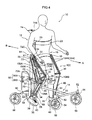
- the walking auxiliary equipment 10 has a walking unit (walking aid unit) 12 to which an drive-assistance device 102 is attached (see also FIG. 4 ), and control thereof is performed by a remote controller (manual switch, described below) 120.
- a walking unit walking aid unit 12 to which an drive-assistance device 102 is attached (see also FIG. 4 ), and control thereof is performed by a remote controller (manual switch, described below) 120.
- the walking auxiliary equipment 10 has the drive-assistance device 102 attached to the walking unit 12 such that a user (wearer) is not conscious thereof (out of the field of vision), such that walking training is performed although a user has a sensation of wearing the walking unit 12.
- a forward driving force needs to be imparted when a user wants to go forward. This is important in order to make a connection between the intention of a user to walk, and the nerves that actually perform walking.
- the present equipment can impart to muscles the movement of each step at a time, and the electrical signal generated from the muscle originates in peripheral nerves and passes through a number of nerve pairs (bundle), and is finally transmitted to the larger nerves of the spine. By repeating this training, rudimentary walking patterns transmitted with reflexes of the nerve pairs are imprinted.
- the walking direction of a person undergoing walking training shown by the arrow A is defined as the front side
- the backwards direction of a person undergoing walking training shown by arrow B is defined as the rear side
- up, down, left and right directions are based on the directions as viewed when facing in the walking direction.
- FIG. 4 is a perspective view of the walking auxiliary equipment 10 in a state of being put onto a person undergoing walking training
- FIG. 5 is a perspective view of the walking auxiliary equipment 10 in a state before putting on.
- the walking auxiliary equipment 10 is configured with the walking unit 12 that is put onto a human body supported by a bogie 14.
- the walking unit 12 is equipped with a lumber frame 16, formed as a trunk (lumber region) portion in substantially a semi-circular shape (U-shape) in plan view, opening to the front.
- the lumber frame 16 is attached to the bogie 14 via an automatic lifting device 64, described below.
- a lumber contact plate 16A is attached to the front face of a left-right direction central portion of the lumber frame 16, with the lumber contact plate 16A making contact with the lumber region on the trunk of a human body positioned inside the lumber frame 16.
- a bracket 17 is fixed to each of both the left and right ends of the lumber contact plate 16A.
- the lumber frame 16 is put onto the lumber region of the trunk of a human body by means of a waist belt 18 connected to the respective ends of both the left and right ends of the lumber frame 16, with the rear portion of the waist belt 18 wrapped around so as to support the buttocks of a human body from below.
- the lumber frame 16 is thereby configured to transmit (support) the weight of a wearer to (on) the bogie 14. Note that illustration of the waist belt 18 is omitted from drawings except for FIG. 4 .
- each top end of the left-right upright frames 20 can be put onto the chest region of a human body via a common chest belt 23. Note that illustration of the chest belt 23 is omitted from drawings except for FIG. 4 .
- above-knee frames 26 with length directions substantially along an up-down direction, serving as coupling portions, are coupled to the lumber frame 16 in the vicinity of the opening ends of the lumber frame 16, further forward than the joint portion to the upright frames 20. Connection is made via hinge shafts 24, each having an axial line that runs substantially along the left-right direction, such that the above-knee frames 26 are capable of swinging about the hinge shafts 24. Intermediate portions of the above-knee frames 26 are fixed to brackets 25.
- the brackets 25 are of substantially L-shape, with one end side of each of the brackets 25 attached to the lumber frame 16 so as to be capable of swinging, and the other end side fixed to the intermediate portion of the above-knee frame 26.
- a first joint K1 corresponding to the hip joint, is configured by the lumber frame 16, the hinge shaft 24, and the above-knee frame 26.
- the rear end of a bracket 30 is fixed to a lower portion of each of the above-knee frames 26, with the brackets 30 each having a length that is substantially along the front-rear direction.
- a below-knee frame 34 serving as a leg portion, is coupled to the bottom end of each of the above-knee frames 26 via a hinge shaft 32 having an axial line running substantially along the left-right direction.
- the below-knee frames 34 have a length direction that is substantially along an up-down direction, and are coupled to the hinge shafts 32 so as to be capable of swinging.
- a second joint K2 corresponding to the knee joint, is configured by the above-knee frame 26, the hinge shaft 32, and the below-knee frame 34.
- brackets 36, 37 is fixed to each upper portion of the below-knee frames 34, and the rear end of a bracket 35, having a length direction that runs substantially along the front-rear direction, is fixed to each lower portion of the below-knee frames 34.
- a below-knee bearing 38 is attached to each of the below-knee frames 34, directly below the second joint K2.
- the below-knee bearings 38 are each formed with a semi-circular shape in plan view, with an opening that faces towards the front, and receive the rear side of a portion below the knee of a human body.
- each of the below-knee bearings 38 can independently be put onto each of the below-knee portions of the different respective left and right legs, by means of leg belts 40, each having an intermediate portion that is fixed to the rear side of the below-knee bearing 38. Note that illustration of the leg belts 40 is omitted from drawings except for FIG. 4 .
- An ankle bearing 39 is attached to the bottom end of each of the below-knee frames 34.
- the ankle bearings 39 are each formed in a semi-circular shape in plan view, open towards the front, and receive the rear side of the ankle of a human body. As shown in FIG. 4 , each of the ankle bearings 39 can independently be put onto the ankle portions on the different left and right legs with a leg belt 40 having an intermediate portion that is fixed to the rear side of the ankle bearing 39. Note that illustration of the leg belts 40 is omitted from drawings except for FIG. 4 .
- the walking unit 12 as explained above is configured to be put onto a human body, with the lumber frame 16 put onto the lumber portion of the lower trunk by the waist belt 18, the top end of each of the upright frames 20 put onto the chest portion of the upper trunk by the chest belt 23, and the below-knee bearings 38 put onto below-knee portions of the leg, and the ankle bearings 39 put onto the ankles, by means of the respective leg belts 40, such that exercise direction of the lower leg is mainly restricted to swing directions about each of the joints K1, K2.
- the bogie 14 is equipped with a center frame 48 having a length direction that runs along the front-rear direction.
- a central portion of a front wheel frame 50 having a length that runs along the left-right direction, is coupled in a fixed manner to the front end of the center frame 48, and support shafts 52, aligned along the up-down direction, are connected to the both the left and right ends of the front wheel frame 50, respectively.
- Arms 54 are supported by each of the support shafts 52, respectively, so as to be capable of swinging about the support shafts 52, and the axial center of respective wheels 56 is rotatably supported at the bottom end of each of the arms 54.
- An up-down direction intermediate portion of an upright pipe 58 having a length that runs along the up-down direction, is coupled in a fixed manner to the rear end of the center frame 48.
- a rear wheel frame 62 having a length direction that runs along the left-right direction, is coupled to the rear of the upright pipe 58 via a rear frame 60.
- the axial centers of wheels 56 are rotatably supported at the two length direction ends of the rear wheel frame 62.
- the bogie 14, and therefore the walking auxiliary equipment 10 is thereby such that contact is only made with the walking surface to be used at the front and rear, total four, wheels 56.
- a suspension structure is employed in the rear frame 60 in order to absorb displacement in the up-down direction.
- the bogie 14 can be configured equipped with two, three, five or more wheels 56.
- the automatic lifting device 64 is provided to the bogie 14.
- the automatic lifting device 64 is provided with an upper block 66 that is fixed to the top end portion of the upright pipe 58, and with a lower block 68 that is fixed in the vicinity of the lower end of the upright pipe 58.
- the upper block 66 and the lower block 68 are fixed to the upright pipe 58, and therefore to the bogie 14, by main bodies 66A, 68A and gripping portions 66B, 68B, each with concave portions, that are fastened together, with the upright pipe 58 inserted into the concave portions in a gripped state.
- a left-right pair of connection plates 70 having length directions that run along the up-down direction, is connected to the main bodies 66A, 68A of the upper and lower blocks 68.
- the automatic lifting device 64 is equipped with an air cylinder 72.
- the air cylinder 72 is configured with a piston 72B provided inside a cylinder 72A (see FIG. 6 ), with one end of an extension and retraction rod 72C positioned outside the cylinder 72A and the other end of the extension and retraction rod 72C fixed to the piston 72B.
- a structure is thereby achieved in which the extension and retraction rod 72C extends and retracts with respect to the cylinder 72A by the piston 72B sliding inside the cylinder 72A.
- the air cylinder 72 has the bottom end portion of the cylinder 72A fixed to the upper block 66, with the extension and retraction rod 72C (the top end thereof) protruding out from the top end of the cylinder 72A so as to move up and down.
- a lifter 74 is fixed to the top end of the extension and retraction rod 72C.
- the lifter 74 has a main body 74A disposed in front of, and parallel to, the air cylinder 72, a top flange 74B, fixed to the top end of the extension and retraction rod 72C and extending rearward from the top end of the main body 74A, and a bottom flange 74C extending out forward from the bottom end of the main body 74A.
- a guide rod 76 is fixed to the lifter 74 at the bottom flange 74C.
- the guide rod 76 is inserted into the upright pipe 58 of the bogie 14 and is supported such that only movement in the up-down direction is permitted. Due thereto, in the automatic lifting device 64, when the extension and retraction rod 72C of the air cylinder 72 extends with respect to the cylinder 72 the lifter 74 is raised from its initial position, while the guide rod 76 is being guided by the upright pipe 58 (by a linear guide disposed therein).
- the bottom flange 74C is positioned at a position above, and in the vicinity of, the upper block 66.
- the maximum stroke of the air cylinder 72 is about 300mm.
- the automatic lifting device 64 is equipped with an air canister 78.
- the air canister 78 is in communication, via an electropneumatic regulator 80, with an air inlet-outlet aperture 72D disposed in the vicinity of the bottom end of the cylinder 72A.
- the electropneumatic regulator 80 is configured with a port that communicates the air inlet-outlet aperture 72D with the air canister 78, and with a port that communicates the air inlet-outlet aperture and the outside (with the atmosphere).
- Each of these ports is capable of being independently opened and closed, with each of the ports controlled by a control device 82, and opened or closed such that the internal pressure within the cylinder 72A, at the air inlet-outlet aperture 72D side of the piston 72B, is a set pressure.
- the control device 82 is electrically connected to a raising and lowering switch 84.
- the electropneumatic regulator 80 controls such that the air pressure of the cylinder 72A becomes a specific pressure, lifting the lifter 74 from the initial position by a specific amount.
- the electropneumatic regulator 80 controls such that the air pressure in the cylinder 72A is lowered to atmospheric pressure.
- the control device 82 may be configured such that the set pressure is appropriately changed, for example if the walking auxiliary equipment 10 is jointly used by plural people or the like, in order to change the raising amount of the lifter 74 according to the body frame (height and weight) of the user.
- the air canister 78, the electropneumatic regulator 80 and the control device 82 are installed at appropriate positions on the bogie 14.
- the air canister 78, the electropneumatic regulator 80 and the control device 82 configure a drive device in the present invention.
- a compressor, an air pump, or the like may be provided in place of an air canister.
- the automatic lifting device 64 supports the above described walking unit 12 with respect to the bogie 14. Specifically, a left-right central portion (rear end portion) of the lumber frame 16, configuring the walking unit 12, is fixed to the bottom flange 74C of the lifter 74, configuring the automatic lifting device 64, by means of fasteners (not shown in the figures).
- the walking auxiliary equipment 10 is of a configuration in which upward movement of the lumber frame 16 of the walking unit 12 as shown in FIG. 4 , and therefore upward movement of the lumber portion of a user, is obtained by raising the lifter 74 from the initial position.
- the initial position of the lifter 74 corresponds to the lumber portion of a user seated on a chair (not shown in the figures), and the raised position of the lifter 74 corresponds to the lumber portion of the user when standing.
- the walking auxiliary equipment 10 is equipped with a drive-assistance device 102 for imparting walking assistance force to a user.
- the drive-assistance device 102 is equipped with: a first actuator 104 that assists flexion of the hip joint; a second actuator 106 that assists flexion of the knee joint; a third actuator 108 that assists extension of the knee joint; and a fourth actuator 110 that assists extension of the hip joint.
- a left-right pair are provided for each of the first to the fourth actuators 104, 106, 108, 110, corresponding to the left and right legs of a user, respectively.
- actuators on the right side will be appended with the suffix "A" and actuators on the left side will be appended with the suffix "B".
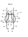
- the first to the fourth actuators 104, 106, 108, 110 are so-called Mc Kibben artificial muscles, pneumatic actuators that contract when supplied with compressed air, generating force in the contracting direction.
- a pneumatic actuator AC is equipped with an inner tube IC that is a swelling and contracting body, and a mesh sleeve MS that is a covering body of a mesh shape that covers the inner tube IC.
- the mesh sleeve MS is, for example, configured from a fibrous material, such as, for example, a high strength non-elastic fiber or the like.
- the two end portion of the mesh sleeve MS in the length (axial) direction are connected to respective length direction end portions of the inner tube IC.
- the inner tube IC swells by supplying air therein. Swelling of the inner tube IC is converted by the mesh sleeve MS into shrinkage in the overall length of the pneumatic actuator AC. Namely, when air is supplied into the pneumatic actuator AC, the length thereof shrinks as the diameter thereof expands. Force F is generated in the contracting direction of the pneumatic actuator AC due to this shrinkage in length.
- the first to the fourth actuators 104, 106, 108, 110 are connected, via switches SW, to a compressor CP.
- the switches SW are provided with an air supply switch (not shown in the figures) and an air vent switch (not shown in the figures).
- the air supply switch is ON and the air vent switch is OFF, compressed air is supplied from the compressor CP to the first to the fourth actuators 104, 106, 108, 110.
- the air vent switch is ON and the air supply switch is OFF, air in the first to the fourth actuators 104, 106, 108, 110 is vented.
- Switches SW are controlled by a control device 112 so as to match the walking movement of a person undergoing walking training. The control method thereof is described below.
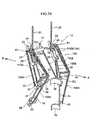
- the left and right first actuators 104 are provided extending in an up-down direction at the front side of the above-knee frames 26, with one end attached to the front end of the bracket 22, and the other end attached to the front end of the bracket 30. Contracting the first actuator 104 generates force that swings the above-knee frame 26 forwards about the first joint K1, namely generates force that flexes the first joint K1. As shown in FIG. 11A , the first actuators 104 are configured to generate force equivalent to the quadriceps muscle A of a human body. Note that, as shown in FIG. 7A , there are two each of the first actuators 104 provided on each of the left and right sides, since flexion of the first joint K1 requires a relatively high force.
- the left and right second actuators 106 are provided extending in an up-down direction at the rear side of the above-knee frame 26, with one end attached to the rear end of the bracket 22, and the other end attached to the bracket 37.
- the second actuators 106 generate force that swings the below-knee frame 34 rearward about the second joint K2, namely generate force that flexes the second joint K2.
- the second actuator 106 is configured to generate force equivalent to that of the triceps surae muscle B in the human body.
- the left and right third actuators 108 are provided extending up and down at the front side of the below-knee frames 34, with one end of each attached to the front end of the bracket 30, and the other end attached to the front end of the bracket 35.
- the third actuators 108 generate force to swing the below-knee frame 34 forward about the second joint K2, namely generate force extending the second joint K2 (see FIG 10B ).
- the third actuators 108 are configured to generate force equivalent to the vastus muscles C in the human body.
- the left and right fourth actuators 110 are provided extending in the up-down direction at the rear side of the above-knee frames 26, with one end attached to the bracket 17, and the other end attached to the bracket 36.
- the first actuators 104 By contracting in unison with the third actuators 108, the first actuators 104 generate force to swing the above-knee frame 26 rearward about the first joint K1, namely generate force to extend the first joint K1.
- the fourth actuator 110 is configured to generate force equivalent to that of the gluteus maximus D in the human body.
- FIG. 7B can also be employed as a configuration to attach the drive-assistance device 102 to the walking unit 12.
- the attachment configuration shown in FIG 7B is equipped with a bracket 140 in place of the bracket 22, and with a plate 150 in place of the bracket 25 and the bracket 30.
- attachment to each of the first actuator 104, the second actuator 106, the third actuator 108 and the fourth actuator 110 is attachment via a ring R.
- a step 160 is provided in place of the ankle bearing 39.
- Other parts of the configuration are similar to those of the attachment configuration described above. Explanation follows of the portions of the attachment configuration of the drive-assistance device 102 to the walking unit 12 that differ from the above described configuration.
- Each of the brackets 140A, 140B is fixed to a bottom end portion of the upright frames 20 and projects out in a diagonal direction forwards and upwards from the two end portions of the lumber frame 16, respectively. Attachment holes 142H are configured in these projecting portions 142.
- the plates 150A, 150B are long flat plate shapes, disposed along the above-knee frames 26 such that the faces of the plates substantially face the left and right directions.
- the brackets 140A, 140B are attached at one end of the plates 150A, 150B (at the proximal end side) through an attachment plate 152, such that each of the brackets 140A, 140B is capable of swinging in the walking front-rear direction (the center of rotation in such cases is shown in the drawings as M).
- a portion at the distal end of each of the plates 150A, 150B is disposed further forward in the walking direction than the bottom end portion of the above-knee frame 26.
- Plural attachment holes 153, 154 are formed in the bottom end edge along the length direction of the plates 150A, 150B.
- the attachment holes 153 are configured in the proximal end side of the plates 150A, 150B, and the attachment holes 154 arc configured in the distal end side of the plates 150A, 150B.
- Fixing portions 156 are formed at intermediate portions at the inside of the plates 150A, 150B. Intermediate portions of the above-knee frames 26 are fixed to the fixing portions 156. End portions at the lumber frame 16 side of the above-knee frame 26 are rotatably attached to the bracket 140.
- One end of the first actuators 104 is attached to the attachment holes 142H of the brackets 140A, 140B via the rings R.
- the other end of the first actuators 104 is attached to the attachment holes 154 at the distal end side of the plates 150A, 150B via the rings R.
- One end of the second actuator 106 is attached to the attachment holes 153 of the proximal end side of the plates 150A, 150B via the rings R.
- the other end of the second actuators 106 is attached to the bracket 37 via the rings R.
- One end of the third actuators 108 is attached to the attachment holes 154 at the distal end side of the plates 150A, 150B via the rings R.
- the other end of the third actuators 108 is attached to the bracket 35 via the rings R.
- One end of the fourth actuators 110 is attached to the bracket 17 via the rings R.
- the other end of the fourth actuators 110 is attached to the bracket 37 via the rings R.
- first actuators 104 the second actuators 106, the third actuators 108, and the fourth actuators 110, it is similar to that in the drive-assistance device 102.
- the step 160 is of substantially an L-shape, and is attached to a lower end portion of the below-knee frame 34 via a hinge 162. One side of the step 160 is disposed so as to be parallel to the floor surface, and a shoe 164 is attached thereto.
- the walking unit 12 is put onto a user who is in a seated posture on a chair (not shown in the figures). Specifically, the waist belt 18 is wrapped around below the buttocks such that the lumber frame 16 is put onto the lumber region, the chest belt 23 is wrapped around the chest region such that the left and right upright frames 20 are fixed to the chest region, the leg belts 40 are wrapped around and put onto a portion below the knee from the outside of the below-knee bearing 38, and the leg belts 40 are wrapped around and put onto the ankle portions from the outside of the ankle bearing 39.
- the user who has put the walking unit 12 on operates the raising and lowering switch 84 to the raising side.
- the control device 82 controls the electropneumatic regulator 80, raising the internal pressure of the cylinder 72A of the air cylinder 72. Due thereto, in the walking auxiliary equipment 10, from the seated position, the extension and retraction rod 72C of the air cylinder 72 extends, the lifter 74 is gradually raised and the walking unit 12 attached to the bottom flange 74C of the lifter 74 makes the user who is wearing the walking unit 12 stand up from the seated state. The user is maintained in an upright position (standing state) since the electropneumatic regulator 80 holds a constant internal pressure in the cylinder 72A.
- an assistant pulls the chair away backwards.
- the user of the walking auxiliary equipment 10 performs walking exercise with a correct gait posture, while being restricted in action by the worn walking unit 12 of multi-jointed structure, and while being prevented from tipping over by the bogie 14 to which the walking unit 12 is attached.
- ON and OFF control of the switch SW is controlled by the control device 112 shown in FIG 9 , supplying air and venting air to the first to the fourth actuators 104, 106, 108, 110.
- each of the left and right actuators are extended and retracted, imparting walking assistance force to a person undergoing walking training using the walking auxiliary equipment 10.
- step 1 air is supplied to the first actuator 104A and the second actuator 106A on the right leg side, and the third actuator 108B and the fourth actuator 110B on the left leg side, thereby contracting these actuators (step 1).
- the other actuators are in a non-air supplied state, namely in the extended venting operation state.
- force is generated to swing the below-knee frame 34 of the right leg side rearwards about the second joint K1, namely force is generated equivalent to that of the triceps surae muscle B of the right leg of a user, and the action to flex the knee of the right leg of a user is assisted.
- venting of air is performed for the first actuator 104A and the 106A of the right leg side and the fourth actuator 108B and the fourth actuator 110B of the left leg side, thereby extending these. Furthermore, accompanying this, air is supplied to the first actuator 104B and the second actuator 106B of the left leg side, and to the third actuator 108A and the fourth actuator 110A of the right leg side, contracting these (step 2).
- force is generated equivalent to that generated by the quadriceps muscle A and the triceps surae muscle B of the left leg side of the user, assisting action to raise the left leg while flexing the left knee.
- force is generated equivalent to that generated by the vastus muscle C and the gluteus maximus D of the right leg side of the user, assisting action to pull the right leg rearward with an extended state to the right knee of a user.
- the first to the fourth actuators 104, 106, 108, 110 repeatedly perform the above operations when the user is performing walking exercise.
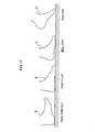
- heel contact A- foot-flat B - heel-off C -toe-off D is performed in sequence.
- Heel contact is the start of the chain of normal walking movement, however when heal contact cannot be made, then ground contact starts from the toes.
- body weight cannot be supported by the whole of the sole of the foot, and excessive load acts on the toes, accompanied by hypertonicity promoting pes equinus.
- the ground contact surface area is narrow (the support air surface is narrow) then maintaining overall balance of the body when standing becomes difficult, and substitutive action tension is induced, such as in the trunk, or the like. Therefore, it is important to perform walking movement in a chain starting from heel contact also from the perspective of securing support base surface area.
- the third actuator 108 is provided to generate force assisting the action to straighten the knee of the user, required to enable a user to perform walking movement in a chain of actions starting from heel contact, and the third actuator 108 is actuated when the user is lowering a raised leg.
- the load acting on the triceps surae muscles can be alleviated when the joint of the leg adopts a dorsiflexed position in the heel contact state. Due thereto, repetitive walking movement is enabled, without excessive load on the triceps surae muscles, and a gradual extension of the range of motion of the leg joints can be expected. Note that plasticity of the triceps surae muscle is promoted by repetition during walking movement of the plantarflexed position and the dorsiflexed position, and progress in that direction is also promoted.
- an assistance force is also generated by the fourth actuator 110 when the third actuator 108 is in an assistance force generated state. Due to this assistance force, the above-knee frame 26 is swung rearwards about the first joint K, actuating pulling of the thigh towards the rear side without flexing the knee of a user, namely assisting action to kick the ground with an upright leg. Consequently, the walking stability of a user can be raised even further.
- the range of motion in the knee flexing action of a user is extended.
- a walking auxiliary equipment 100 as a walking auxiliary equipment according to a second exemplary embodiment of the present invention.
- actuation of the first actuators 104 is automatic in the above described walking auxiliary equipment 10 according to the first exemplary embodiment
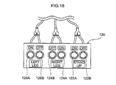
- the first to the fourth actuators 104, 106, 108, 110 are actuated by manual operation using a manual switch 120 shown in FIG. 18 .
- the manual switch 120 is equipped with: a stand-up ON switch 122A generating assistance force when a user is standing up, and a stand-up OFF switch 122B that switches off generation of this assistance force; a right leg ON switch 124A that generates assistance force when a user is striding out with the right leg, and a right leg OFF switch 124B that switches off generation of this assistance force; and a left leg ON switch 126A that generates assistance force when a user is striding out with the left leg, and a left leg OFF switch 126B that switches off generation of this assistance force.
- the stand-up ON switch 122A and the stand-up OFF switch 122B are connected to the left and right third actuator 108A and 108B, and to the left and right fourth actuator 110A and 110B.
- the stand-up ON switch 122A continues to be pressed, air continues to be supplied to the actuators to which it is connected, however when pressing is released, the supply of air to the actuators is terminated.
- the actuators to which supply of air is terminated remain in the state they were in at the time when supply was terminated.
- the first actuator 104A and the second actuator 106A of the right leg side, and the third actuator 108B and the fourth actuator 110B of the left leg side, are connected to the right leg ON switch 124A and the right leg OFF switch 124B.
- first actuator 104B and the second actuator 106B of the left leg side, and the third actuator 108A and the fourth actuator 110A of the right leg side are connected to the left leg ON switch 126A and the left leg OFF switch 126B.
- configuration may be made provided only with switches 124, 126 for raising and lowering the right leg and the left leg.
- switches 124, 126 for raising and lowering the right leg and the left leg.
- configuration may be made in which the right leg or the left leg is raised by pressing, and the right leg or the left leg is lowered by releasing pressing, or, as shown in FIG. 20 , configuration may be made in which a switch is provided for raising the right leg or the left leg and a switch is provided for lowering the right leg or the left leg, such that the legs can be raised and lowered by pressing each of the respective switches.
- the stand-up ON switch 122 When a user is standing up (standing position), the stand-up ON switch 122 is pressed, contracting the third actuators 108A, 108B on the left and right sides, and fourth actuators 110A, 110B on the left and right sides. Due thereto, the below-knee frames 34 swing forward about the second joints K2, and the second joints K2 are extended, and in addition the left and right above-knee frames 26 swing rearward about the first joints K1, extending the first joints K1. Namely, force to assist standing-up action of a user is generated.
- the right leg ON switch 124A When the user performs walking movement, the right leg ON switch 124A is pressed so as to coincide with striding out forward with the right leg, contracting the first actuator 104A and the second actuator 106A of the right leg side, and contracting the third actuator 108B and the fourth actuator 110B of the left leg side. Due thereto, the above-knee frame 26 of the right leg side swings forward about the first joint K1, flexing the first joint K1, and also the below-knee frame 34 on the right leg side swings rearward about the second joint K2, flexing the second joint K2.
- the right leg is raised while the right knee of a user is flexed (right leg thigh raising), and force is generated assisting movement to pull the left leg rearward (kicking the ground surface with the left leg) in the state in which the left knee is extended.
- the above-knee frame 26 on the left leg side swings forward about the first joint K1 together with the below-knee frame 34 on the left leg side swinging rearward about the second joint K2. Due thereto, the first joint K1 on the left leg side is flexed, and the second joint K2 on the left leg side is flexed.
- the third actuator 108A and the fourth actuator 110A on the right leg side are contracted, and, with the second joint K2 in an extended state, the above-knee frame 26 swings rearward about the first joint K1 and the first joint K1 is extended.
- the right leg of a user is raised (right leg thigh raising) with the right knee flexed, and force is generated to assist action to pull the left leg rearward (left leg ground kicking) with the left knee in an extended state.
- performing of good walking exercise is enabled for the user of the walking auxiliary equipment 100.
- the timing with which air is supplied to the first to the fourth actuators 104, 106, 108, 110, the flow rate thereof, and the like are capable of being changed to match the condition of a user, and the shrinking (contracting) and relaxation (extension) of the first to the fourth actuators 104, 106, 108, 110 is capable of gradually being changed. Due thereto, a user is enabled to perform safe walking movement.
- the walking auxiliary equipment 100 Furthermore, by manual (hand) operation of the walking auxiliary equipment 100, the capability arises to determine the level of muscle tone of a user and the presence or absence of involuntary movements, and a safe range of range of motion for the user can be verified. Consequently, the verified data is capable of serving a useful function when setting the control parameters in the automatic walking auxiliary equipment 10 explained in the first exemplary embodiment.
- the first joint K1 and the second joint K2 can be extended at the same time, not only resulting in being able assist maintenance of a standing posture of a user, but the weight of a user that acts on the flexed knees of a user can be suppressed by the below-knee bearing 38, resulting in being able to also obtain relieve of pain in the knee of a user.
- pneumatic actuators are employed as the first to the fourth actuators in the present exemplary embodiment, however wire wound onto pulleys and wound out from pulleys, under actuation from a motor, may be employed in the first to the fourth actuators. It is also not essential for all of the first to the fourth actuators to be provided.
- the walking auxiliary equipments 10, 100 included the bogie 14, however a bogie is not an essential element of the configuration of the walking auxiliary equipment.
Landscapes
- Health & Medical Sciences (AREA)
- Epidemiology (AREA)
- Pain & Pain Management (AREA)
- Physical Education & Sports Medicine (AREA)
- Rehabilitation Therapy (AREA)
- Life Sciences & Earth Sciences (AREA)
- Animal Behavior & Ethology (AREA)
- General Health & Medical Sciences (AREA)
- Public Health (AREA)
- Veterinary Medicine (AREA)
- Engineering & Computer Science (AREA)
- Robotics (AREA)
- Mechanical Engineering (AREA)
- Rehabilitation Tools (AREA)
Applications Claiming Priority (2)
| Application Number | Priority Date | Filing Date | Title |
|---|---|---|---|
| JP2007258994 | 2007-10-02 | ||
| PCT/JP2008/058084 WO2009044568A1 (fr) | 2007-10-02 | 2008-04-25 | Équipement auxiliaire pour la marche |
Publications (2)
| Publication Number | Publication Date |
|---|---|
| EP2193774A1 true EP2193774A1 (fr) | 2010-06-09 |
| EP2193774A4 EP2193774A4 (fr) | 2013-05-01 |
Family
ID=40526000
Family Applications (1)
| Application Number | Title | Priority Date | Filing Date |
|---|---|---|---|
| EP08752127.4A Withdrawn EP2193774A4 (fr) | 2007-10-02 | 2008-04-25 | Équipement auxiliaire pour la marche |
Country Status (4)
| Country | Link |
|---|---|
| US (1) | US20100270771A1 (fr) |
| EP (1) | EP2193774A4 (fr) |
| JP (1) | JP5283282B2 (fr) |
| WO (1) | WO2009044568A1 (fr) |
Cited By (9)
| Publication number | Priority date | Publication date | Assignee | Title |
|---|---|---|---|---|
| WO2013167783A1 (fr) * | 2012-05-09 | 2013-11-14 | Universidad De Alcalá | Déambulateur orthopédique à électronique d'actionnement |
| CN103622796A (zh) * | 2013-12-17 | 2014-03-12 | 哈尔滨工程大学 | 一种穿戴式下肢康复训练装置 |
| WO2014177206A1 (fr) | 2013-05-01 | 2014-11-06 | Liw Care Technology Sp. Z O.O. | Dispositif réciproque d'assistance à l'apprentissage de la démarche |
| WO2015032696A1 (fr) * | 2013-09-06 | 2015-03-12 | Commissariat A L`Energie Atomique Et Aux Energies Alternatives | Membre inferieur d'un exosquelette ou d'un robot bipede |
| EP2856997A3 (fr) * | 2013-09-17 | 2015-08-05 | Kabushiki Kaisha Yaskawa Denki | Dispositif d'assistance au mouvement |
| EP2914230A4 (fr) * | 2012-11-01 | 2016-07-13 | British Columbia Inst Of Technology | Système de mobilité contenant un ensemble exosquelette supporté amovible sur une base à roue |
| WO2017042753A1 (fr) * | 2015-09-13 | 2017-03-16 | Joseph Rogozinski | Dispositifs permettant aux personnes handicapées de se tenir debout, de marcher et d'activer leur corps |
| ITUB20155017A1 (it) * | 2015-11-02 | 2017-05-02 | Luca Simone Poli | Esoscheletro e relativo procedimento di funzionamento |
| RU225830U1 (ru) * | 2024-01-29 | 2024-05-07 | Общество с ограниченной ответственностью "СТЕП ФОРВАРД" (ООО "СТЕП ФОРВАРД") | Регулируемый подлокотник тренировочного комплекса для формирования двигательных навыков ходьбы у детей с детским церебральным параличом и с заболеваниями опорно-двигательного аппарата |
Families Citing this family (44)
| Publication number | Priority date | Publication date | Assignee | Title |
|---|---|---|---|---|
| US8567185B1 (en) * | 2010-02-16 | 2013-10-29 | Vecna Technologies, Inc. | High efficiency actuator method, system and apparatus |
| KR200456400Y1 (ko) | 2010-03-09 | 2011-10-27 | 서영춘 | 허리 보호 지지장치 |
| JP4987148B1 (ja) * | 2011-07-22 | 2012-07-25 | 圭治郎 山本 | 関節運動アシスト装置 |
| JP5909063B2 (ja) * | 2011-09-06 | 2016-04-26 | 国立大学法人 和歌山大学 | パワーアシストロボット装置 |
| EP2754538B1 (fr) | 2011-09-06 | 2019-10-23 | Wakayama University | Dispositif robotique à assistance de puissance et procédé de commande de celui-ci |
| CN104540489B (zh) | 2012-08-17 | 2018-04-03 | 罗伯特·卡尔洛维奇 | 移动辅助装置 |
| US11406555B2 (en) * | 2012-08-17 | 2022-08-09 | Core Mobility Solutions Inc. | Mobility assistance device |
| ITRM20120482A1 (it) * | 2012-10-09 | 2014-04-10 | Uni Campus Bio Medico Di Rom A | Dispositivo robotico per l'assistenza e la riabilitazione degli arti inferiori. |
| KR101325066B1 (ko) * | 2012-10-22 | 2013-11-05 | 한국생산기술연구원 | 뇌졸중 환자의 보행재활 치료용 로봇 |
| US20160030273A1 (en) * | 2012-12-07 | 2016-02-04 | Kyung-Hee Han | Multi-purpose solar power safe walker |
| KR101358943B1 (ko) * | 2013-02-12 | 2014-02-07 | 한국과학기술연구원 | 보행 재활 로봇의 골반 지지 장치 |
| US11135124B2 (en) * | 2013-07-09 | 2021-10-05 | John Threlfall | External structural brace apparatus |
| US9861549B2 (en) * | 2013-08-08 | 2018-01-09 | Core Mobility Solutions, Inc. | Mobility assistance device |
| JP6232613B2 (ja) * | 2013-09-27 | 2017-11-22 | 国立大学法人 鹿児島大学 | 片麻痺患者用歩行訓練装置 |
| JP5525648B1 (ja) * | 2013-11-27 | 2014-06-18 | 俊夫 眞島 | 認知症専用じりつ歩行補助具 |
| US9616282B2 (en) * | 2013-12-13 | 2017-04-11 | ALT Innovations LLC | Multi-modal gait-based non-invasive therapy platform |
| US10881572B2 (en) * | 2013-12-13 | 2021-01-05 | ALT Innovations LLC | Natural assist simulated gait therapy adjustment system |
| US10315067B2 (en) * | 2013-12-13 | 2019-06-11 | ALT Innovations LLC | Natural assist simulated gait adjustment therapy system |
| US20210154065A1 (en) * | 2014-07-14 | 2021-05-27 | Exokinetics, Inc. | Elevating walker chair and convertible seat |
| JP2016039857A (ja) * | 2014-08-12 | 2016-03-24 | 国立大学法人 名古屋工業大学 | 歩行機 |
| CN104786209B (zh) * | 2015-04-22 | 2017-01-11 | 陆新田 | 载人变形机器人 |
| DK3207909T3 (da) * | 2016-02-18 | 2019-12-09 | Hexowheel | Støttestruktur |
| JP6678334B2 (ja) * | 2016-03-09 | 2020-04-08 | パナソニックIpマネジメント株式会社 | 生活支援システム、歩行アシストロボット及び生活支援方法 |
| US10085906B2 (en) | 2016-06-21 | 2018-10-02 | Hefei University Of Technology | Medical apparatus for standing aid |
| ES2936789T3 (es) * | 2016-09-08 | 2023-03-22 | Trexo Robotics Inc | Dispositivo móvil de órtesis motorizado que soporta peso |
| US10292892B2 (en) * | 2016-09-12 | 2019-05-21 | Lunghwa University Of Science And Technology | Pneumatic lower extremity gait rehabilitation training system |
| US11135119B2 (en) * | 2017-04-21 | 2021-10-05 | Board Of Regents, The University Of Texas System | Adaptable robotic gait trainer |
| CN107174477B (zh) * | 2017-05-18 | 2020-10-09 | 宿州市思达特科技有限公司 | 一种智能可穿戴式脑瘫儿康复机器人 |
| US10292891B2 (en) * | 2017-06-02 | 2019-05-21 | Ohio State Innovation Foundation | Active robotic walker and associated method |
| CA3072622A1 (fr) | 2017-08-29 | 2019-03-07 | Roam Robotics Inc. | Systeme et procede de reconnaissance d'intention semi-supervisee |
| KR102443794B1 (ko) * | 2017-09-04 | 2022-09-16 | 삼성전자주식회사 | 운동 보조 장치 |
| US10758774B2 (en) | 2017-10-06 | 2020-09-01 | ALT Innovations LLC | Walk therapy station |
| WO2019100072A1 (fr) * | 2017-11-20 | 2019-05-23 | The Regents Of The University Of California | Mécanisme de support d'exosquelette pour un exosquelette médical |
| CN108743260B (zh) * | 2018-06-05 | 2020-08-11 | 河北雅诗莉医药科技有限公司 | 一种具有多级摇臂结构的智能移位康复车 |
| CN109718065B (zh) * | 2018-12-13 | 2024-04-26 | 上海电子信息职业技术学院 | 移动助力装置 |
| WO2021119512A1 (fr) | 2019-12-13 | 2021-06-17 | Roam Robotics Inc. | Dispositif électrique pouvant aider un utilisateur pendant le ski |
| CN115605170A (zh) | 2020-02-25 | 2023-01-13 | 漫游机械人技术公司(Us) | 用于移动机器人的流体致动器系统和方法 |
| CN111728830B (zh) * | 2020-07-03 | 2022-05-03 | 四川省康复辅具技术服务中心(四川省民政康复医院) | 一种儿童步健器 |
| JP7527231B2 (ja) | 2020-09-30 | 2024-08-02 | 株式会社イノフィス | 歩行補助装置 |
| WO2022071017A1 (fr) * | 2020-09-30 | 2022-04-07 | 株式会社イノフィス | Dispositif d'aide à l'ambulation |
| KR102436820B1 (ko) * | 2020-11-12 | 2022-08-26 | 선문대학교 산학협력단 | 하지 재활용 보행기 |
| US11883714B2 (en) | 2020-12-24 | 2024-01-30 | ALT Innovations LLC | Upper body gait ergometer and gait trainer |
| US11938073B2 (en) * | 2022-04-08 | 2024-03-26 | Gigstride Corporation | Devices for assisting limb movement |
| WO2024151680A1 (fr) * | 2023-01-09 | 2024-07-18 | Sarcos Corp. | Exosquelette de marche |
Citations (3)
| Publication number | Priority date | Publication date | Assignee | Title |
|---|---|---|---|---|
| WO2004043307A1 (fr) * | 2002-11-01 | 2004-05-27 | Benito Ferrati | Appareil orthopedique pour la marche et la reeducation de personnes handicapees |
| JP2006340852A (ja) * | 2005-06-08 | 2006-12-21 | Natl Rehabilitation Center For The Disabled | 着用形関節駆動装置 |
| JP2007014698A (ja) * | 2005-07-11 | 2007-01-25 | Tokyo Univ Of Science | 歩行補助装置 |
Family Cites Families (1)
| Publication number | Priority date | Publication date | Assignee | Title |
|---|---|---|---|---|
| JP2006087548A (ja) * | 2004-09-22 | 2006-04-06 | Masanori Sugisaka | マッスルトラウザ |
-
2008
- 2008-04-25 WO PCT/JP2008/058084 patent/WO2009044568A1/fr active Application Filing
- 2008-04-25 US US12/675,739 patent/US20100270771A1/en not_active Abandoned
- 2008-04-25 JP JP2009535989A patent/JP5283282B2/ja active Active
- 2008-04-25 EP EP08752127.4A patent/EP2193774A4/fr not_active Withdrawn
Patent Citations (3)
| Publication number | Priority date | Publication date | Assignee | Title |
|---|---|---|---|---|
| WO2004043307A1 (fr) * | 2002-11-01 | 2004-05-27 | Benito Ferrati | Appareil orthopedique pour la marche et la reeducation de personnes handicapees |
| JP2006340852A (ja) * | 2005-06-08 | 2006-12-21 | Natl Rehabilitation Center For The Disabled | 着用形関節駆動装置 |
| JP2007014698A (ja) * | 2005-07-11 | 2007-01-25 | Tokyo Univ Of Science | 歩行補助装置 |
Non-Patent Citations (1)
| Title |
|---|
| See also references of WO2009044568A1 * |
Cited By (15)
| Publication number | Priority date | Publication date | Assignee | Title |
|---|---|---|---|---|
| WO2013167783A1 (fr) * | 2012-05-09 | 2013-11-14 | Universidad De Alcalá | Déambulateur orthopédique à électronique d'actionnement |
| US9849048B2 (en) | 2012-11-01 | 2017-12-26 | British Columbia Institute Of Technology | Mobility system including an exoskeleton assembly releasably supported on a wheeled base |
| EP2914230A4 (fr) * | 2012-11-01 | 2016-07-13 | British Columbia Inst Of Technology | Système de mobilité contenant un ensemble exosquelette supporté amovible sur une base à roue |
| WO2014177206A1 (fr) | 2013-05-01 | 2014-11-06 | Liw Care Technology Sp. Z O.O. | Dispositif réciproque d'assistance à l'apprentissage de la démarche |
| US10786414B2 (en) | 2013-09-06 | 2020-09-29 | Commissariat A L Energie Atomique Et Aux Energies Alternatives | Lower limb of an exoskeleton or a bipedal robot |
| WO2015032696A1 (fr) * | 2013-09-06 | 2015-03-12 | Commissariat A L`Energie Atomique Et Aux Energies Alternatives | Membre inferieur d'un exosquelette ou d'un robot bipede |
| FR3010343A1 (fr) * | 2013-09-06 | 2015-03-13 | Commissariat Energie Atomique | Membre inferieur d'un exosquelette ou d'un robot bipede |
| EP2856997A3 (fr) * | 2013-09-17 | 2015-08-05 | Kabushiki Kaisha Yaskawa Denki | Dispositif d'assistance au mouvement |
| CN103622796B (zh) * | 2013-12-17 | 2016-01-27 | 哈尔滨工程大学 | 一种穿戴式下肢康复训练装置 |
| CN103622796A (zh) * | 2013-12-17 | 2014-03-12 | 哈尔滨工程大学 | 一种穿戴式下肢康复训练装置 |
| WO2017042753A1 (fr) * | 2015-09-13 | 2017-03-16 | Joseph Rogozinski | Dispositifs permettant aux personnes handicapées de se tenir debout, de marcher et d'activer leur corps |
| ITUB20155017A1 (it) * | 2015-11-02 | 2017-05-02 | Luca Simone Poli | Esoscheletro e relativo procedimento di funzionamento |
| EP3162515A1 (fr) * | 2015-11-02 | 2017-05-03 | Poli, Luca Simone | Exoskeleton |
| WO2017077438A1 (fr) * | 2015-11-02 | 2017-05-11 | Poli Luca Simone | Exosquelette et son procédé d'actionnement |
| RU225830U1 (ru) * | 2024-01-29 | 2024-05-07 | Общество с ограниченной ответственностью "СТЕП ФОРВАРД" (ООО "СТЕП ФОРВАРД") | Регулируемый подлокотник тренировочного комплекса для формирования двигательных навыков ходьбы у детей с детским церебральным параличом и с заболеваниями опорно-двигательного аппарата |
Also Published As
| Publication number | Publication date |
|---|---|
| US20100270771A1 (en) | 2010-10-28 |
| EP2193774A4 (fr) | 2013-05-01 |
| WO2009044568A1 (fr) | 2009-04-09 |
| JPWO2009044568A1 (ja) | 2011-02-03 |
| JP5283282B2 (ja) | 2013-09-04 |
Similar Documents
| Publication | Publication Date | Title |
|---|---|---|
| EP2193774A1 (fr) | Équipement auxiliaire pour la marche | |
| US6666798B2 (en) | Therapeutic and rehabilitation apparatus | |
| US20230414381A1 (en) | Powered gait assistance systems | |
| Colombo et al. | Treadmill training of paraplegic patients using a robotic orthosis | |
| US11324653B2 (en) | Exoskeleton for assisting human movement | |
| KR100942968B1 (ko) | 재활치료용 운동기구 | |
| Colombo et al. | Driven gait orthosis to do locomotor training of paraplegic patients | |
| US6666831B1 (en) | Method, apparatus and system for automation of body weight support training (bwst) of biped locomotion over a treadmill using a programmable stepper device (psd) operating like an exoskeleton drive system from a fixed base | |
| Sanchez-Manchola et al. | Development of a robotic lower-limb exoskeleton for gait rehabilitation: AGoRA exoskeleton | |
| KR100946186B1 (ko) | 하지의 로봇 보조기 | |
| JP7365356B2 (ja) | 医療用歩行器 | |
| KR100907425B1 (ko) | 인체용 다리의 재활장치 | |
| KR20170139035A (ko) | 수직 위치에서의 보행의 구동과 함께 정와위 또는 부분 와위 자세에서 사람의 하지를 구동하기 위한 장치 | |
| CN107468464A (zh) | 下肢多功能锻炼装置 | |
| CN112370305B (zh) | 一种下肢康复训练外骨骼机器人 | |
| KR101797967B1 (ko) | 하지 보조 보행기 | |
| KR20150105950A (ko) | 섀도우 레그를 가진 재활 장치 | |
| CN108652925B (zh) | 一种助行康复及步态矫正系统 | |
| CN208710413U (zh) | 一种下肢康复训练机 | |
| JP2001008987A (ja) | 交差歩行訓練器 | |
| CN217162570U (zh) | 一种下肢自主康复训练装置 | |
| CN110947158A (zh) | 一种基于椭圆运动的助行训练装置 | |
| KR102531025B1 (ko) | 상지 및 하지의 근력 강화 재활운동 로봇장치 | |
| CN108836748A (zh) | 一种下肢康复外骨骼系统 | |
| TWM485715U (zh) | 行動輔助裝置 |
Legal Events
| Date | Code | Title | Description |
|---|---|---|---|
| PUAI | Public reference made under article 153(3) epc to a published international application that has entered the european phase |
Free format text: ORIGINAL CODE: 0009012 |
|
| 17P | Request for examination filed |
Effective date: 20100226 |
|
| AK | Designated contracting states |
Kind code of ref document: A1 Designated state(s): AT BE BG CH CY CZ DE DK EE ES FI FR GB GR HR HU IE IS IT LI LT LU LV MC MT NL NO PL PT RO SE SI SK TR |
|
| AX | Request for extension of the european patent |
Extension state: AL BA MK RS |
|
| DAX | Request for extension of the european patent (deleted) | ||
| A4 | Supplementary search report drawn up and despatched |
Effective date: 20130402 |
|
| RIC1 | Information provided on ipc code assigned before grant |
Ipc: B25J 9/00 20060101ALI20130325BHEP Ipc: A61H 3/04 20060101ALI20130325BHEP Ipc: A61H 3/00 20060101AFI20130325BHEP |
|
| STAA | Information on the status of an ep patent application or granted ep patent |
Free format text: STATUS: THE APPLICATION IS DEEMED TO BE WITHDRAWN |
|
| 18D | Application deemed to be withdrawn |
Effective date: 20131030 |