EP2192970B1 - Trockenmittelpatrone für eine druckluftaufbereitungsanlage und verfahren zur herstellung einer trockenmittelpatrone - Google Patents
Trockenmittelpatrone für eine druckluftaufbereitungsanlage und verfahren zur herstellung einer trockenmittelpatrone Download PDFInfo
- Publication number
- EP2192970B1 EP2192970B1 EP08801962.5A EP08801962A EP2192970B1 EP 2192970 B1 EP2192970 B1 EP 2192970B1 EP 08801962 A EP08801962 A EP 08801962A EP 2192970 B1 EP2192970 B1 EP 2192970B1
- Authority
- EP
- European Patent Office
- Prior art keywords
- air
- combination filter
- drying agent
- carrier element
- filter
- Prior art date
- Legal status (The legal status is an assumption and is not a legal conclusion. Google has not performed a legal analysis and makes no representation as to the accuracy of the status listed.)
- Not-in-force
Links
- 239000002274 desiccant Substances 0.000 title claims description 138
- 238000004519 manufacturing process Methods 0.000 title claims description 7
- 230000008929 regeneration Effects 0.000 claims description 24
- 238000011069 regeneration method Methods 0.000 claims description 24
- 238000007789 sealing Methods 0.000 claims description 20
- 239000002245 particle Substances 0.000 claims description 14
- 238000000034 method Methods 0.000 claims description 10
- 238000001035 drying Methods 0.000 claims description 7
- 238000002360 preparation method Methods 0.000 claims description 3
- 239000000463 material Substances 0.000 description 17
- 239000000853 adhesive Substances 0.000 description 7
- 230000001070 adhesive effect Effects 0.000 description 7
- 238000011045 prefiltration Methods 0.000 description 5
- 230000006835 compression Effects 0.000 description 4
- 238000007906 compression Methods 0.000 description 4
- 238000004804 winding Methods 0.000 description 3
- 238000004581 coalescence Methods 0.000 description 2
- 239000000839 emulsion Substances 0.000 description 2
- 239000007788 liquid Substances 0.000 description 2
- 238000004064 recycling Methods 0.000 description 2
- CBENFWSGALASAD-UHFFFAOYSA-N Ozone Chemical compound [O-][O+]=O CBENFWSGALASAD-UHFFFAOYSA-N 0.000 description 1
- 239000002313 adhesive film Substances 0.000 description 1
- 239000000443 aerosol Substances 0.000 description 1
- 238000004140 cleaning Methods 0.000 description 1
- 238000010276 construction Methods 0.000 description 1
- 239000000356 contaminant Substances 0.000 description 1
- 238000011109 contamination Methods 0.000 description 1
- 230000006378 damage Effects 0.000 description 1
- 230000001419 dependent effect Effects 0.000 description 1
- 230000008021 deposition Effects 0.000 description 1
- 230000000694 effects Effects 0.000 description 1
- 238000011049 filling Methods 0.000 description 1
- 238000011010 flushing procedure Methods 0.000 description 1
- 230000005484 gravity Effects 0.000 description 1
- 230000001771 impaired effect Effects 0.000 description 1
- 238000009434 installation Methods 0.000 description 1
- 230000002452 interceptive effect Effects 0.000 description 1
- 239000002184 metal Substances 0.000 description 1
- 239000000203 mixture Substances 0.000 description 1
- 239000010908 plant waste Substances 0.000 description 1
- 230000008092 positive effect Effects 0.000 description 1
- 230000029058 respiratory gaseous exchange Effects 0.000 description 1
- 238000005245 sintering Methods 0.000 description 1
- 239000007787 solid Substances 0.000 description 1
- 238000003860 storage Methods 0.000 description 1
- 239000000725 suspension Substances 0.000 description 1
- 238000011144 upstream manufacturing Methods 0.000 description 1
- 239000002699 waste material Substances 0.000 description 1
Images



Classifications
-
- B—PERFORMING OPERATIONS; TRANSPORTING
- B60—VEHICLES IN GENERAL
- B60T—VEHICLE BRAKE CONTROL SYSTEMS OR PARTS THEREOF; BRAKE CONTROL SYSTEMS OR PARTS THEREOF, IN GENERAL; ARRANGEMENT OF BRAKING ELEMENTS ON VEHICLES IN GENERAL; PORTABLE DEVICES FOR PREVENTING UNWANTED MOVEMENT OF VEHICLES; VEHICLE MODIFICATIONS TO FACILITATE COOLING OF BRAKES
- B60T17/00—Component parts, details, or accessories of power brake systems not covered by groups B60T8/00, B60T13/00 or B60T15/00, or presenting other characteristic features
- B60T17/002—Air treatment devices
- B60T17/004—Draining and drying devices
-
- B—PERFORMING OPERATIONS; TRANSPORTING
- B01—PHYSICAL OR CHEMICAL PROCESSES OR APPARATUS IN GENERAL
- B01D—SEPARATION
- B01D45/00—Separating dispersed particles from gases or vapours by gravity, inertia, or centrifugal forces
- B01D45/04—Separating dispersed particles from gases or vapours by gravity, inertia, or centrifugal forces by utilising inertia
- B01D45/06—Separating dispersed particles from gases or vapours by gravity, inertia, or centrifugal forces by utilising inertia by reversal of direction of flow
-
- B—PERFORMING OPERATIONS; TRANSPORTING
- B01—PHYSICAL OR CHEMICAL PROCESSES OR APPARATUS IN GENERAL
- B01D—SEPARATION
- B01D46/00—Filters or filtering processes specially modified for separating dispersed particles from gases or vapours
- B01D46/0002—Casings; Housings; Frame constructions
- B01D46/0005—Mounting of filtering elements within casings, housings or frames
-
- B—PERFORMING OPERATIONS; TRANSPORTING
- B01—PHYSICAL OR CHEMICAL PROCESSES OR APPARATUS IN GENERAL
- B01D—SEPARATION
- B01D46/00—Filters or filtering processes specially modified for separating dispersed particles from gases or vapours
- B01D46/0027—Filters or filtering processes specially modified for separating dispersed particles from gases or vapours with additional separating or treating functions
- B01D46/003—Filters or filtering processes specially modified for separating dispersed particles from gases or vapours with additional separating or treating functions including coalescing means for the separation of liquid
- B01D46/0031—Filters or filtering processes specially modified for separating dispersed particles from gases or vapours with additional separating or treating functions including coalescing means for the separation of liquid with collecting, draining means
-
- B—PERFORMING OPERATIONS; TRANSPORTING
- B01—PHYSICAL OR CHEMICAL PROCESSES OR APPARATUS IN GENERAL
- B01D—SEPARATION
- B01D46/00—Filters or filtering processes specially modified for separating dispersed particles from gases or vapours
- B01D46/0084—Filters or filtering processes specially modified for separating dispersed particles from gases or vapours provided with safety means
- B01D46/0087—Bypass or safety valves
-
- B—PERFORMING OPERATIONS; TRANSPORTING
- B01—PHYSICAL OR CHEMICAL PROCESSES OR APPARATUS IN GENERAL
- B01D—SEPARATION
- B01D46/00—Filters or filtering processes specially modified for separating dispersed particles from gases or vapours
- B01D46/0084—Filters or filtering processes specially modified for separating dispersed particles from gases or vapours provided with safety means
- B01D46/0089—Anti-return means
-
- B—PERFORMING OPERATIONS; TRANSPORTING
- B01—PHYSICAL OR CHEMICAL PROCESSES OR APPARATUS IN GENERAL
- B01D—SEPARATION
- B01D46/00—Filters or filtering processes specially modified for separating dispersed particles from gases or vapours
- B01D46/10—Particle separators, e.g. dust precipitators, using filter plates, sheets or pads having plane surfaces
- B01D46/106—Ring-shaped filtering elements
-
- B—PERFORMING OPERATIONS; TRANSPORTING
- B01—PHYSICAL OR CHEMICAL PROCESSES OR APPARATUS IN GENERAL
- B01D—SEPARATION
- B01D46/00—Filters or filtering processes specially modified for separating dispersed particles from gases or vapours
- B01D46/24—Particle separators, e.g. dust precipitators, using rigid hollow filter bodies
- B01D46/2403—Particle separators, e.g. dust precipitators, using rigid hollow filter bodies characterised by the physical shape or structure of the filtering element
- B01D46/2411—Filter cartridges
- B01D46/2414—End caps including additional functions or special forms
-
- B—PERFORMING OPERATIONS; TRANSPORTING
- B01—PHYSICAL OR CHEMICAL PROCESSES OR APPARATUS IN GENERAL
- B01D—SEPARATION
- B01D46/00—Filters or filtering processes specially modified for separating dispersed particles from gases or vapours
- B01D46/56—Filters or filtering processes specially modified for separating dispersed particles from gases or vapours with multiple filtering elements, characterised by their mutual disposition
- B01D46/62—Filters or filtering processes specially modified for separating dispersed particles from gases or vapours with multiple filtering elements, characterised by their mutual disposition connected in series
-
- B—PERFORMING OPERATIONS; TRANSPORTING
- B01—PHYSICAL OR CHEMICAL PROCESSES OR APPARATUS IN GENERAL
- B01D—SEPARATION
- B01D53/00—Separation of gases or vapours; Recovering vapours of volatile solvents from gases; Chemical or biological purification of waste gases, e.g. engine exhaust gases, smoke, fumes, flue gases, aerosols
- B01D53/26—Drying gases or vapours
- B01D53/261—Drying gases or vapours by adsorption
-
- F—MECHANICAL ENGINEERING; LIGHTING; HEATING; WEAPONS; BLASTING
- F15—FLUID-PRESSURE ACTUATORS; HYDRAULICS OR PNEUMATICS IN GENERAL
- F15B—SYSTEMS ACTING BY MEANS OF FLUIDS IN GENERAL; FLUID-PRESSURE ACTUATORS, e.g. SERVOMOTORS; DETAILS OF FLUID-PRESSURE SYSTEMS, NOT OTHERWISE PROVIDED FOR
- F15B21/00—Common features of fluid actuator systems; Fluid-pressure actuator systems or details thereof, not covered by any other group of this subclass
- F15B21/04—Special measures taken in connection with the properties of the fluid
- F15B21/041—Removal or measurement of solid or liquid contamination, e.g. filtering
-
- F—MECHANICAL ENGINEERING; LIGHTING; HEATING; WEAPONS; BLASTING
- F15—FLUID-PRESSURE ACTUATORS; HYDRAULICS OR PNEUMATICS IN GENERAL
- F15B—SYSTEMS ACTING BY MEANS OF FLUIDS IN GENERAL; FLUID-PRESSURE ACTUATORS, e.g. SERVOMOTORS; DETAILS OF FLUID-PRESSURE SYSTEMS, NOT OTHERWISE PROVIDED FOR
- F15B21/00—Common features of fluid actuator systems; Fluid-pressure actuator systems or details thereof, not covered by any other group of this subclass
- F15B21/04—Special measures taken in connection with the properties of the fluid
- F15B21/048—Arrangements for compressed air preparation, e.g. comprising air driers, air condensers, filters, lubricators or pressure regulators
-
- B—PERFORMING OPERATIONS; TRANSPORTING
- B01—PHYSICAL OR CHEMICAL PROCESSES OR APPARATUS IN GENERAL
- B01D—SEPARATION
- B01D2265/00—Casings, housings or mounting for filters specially adapted for separating dispersed particles from gases or vapours
- B01D2265/02—Non-permanent measures for connecting different parts of the filter
- B01D2265/021—Anti-rotational means
-
- B—PERFORMING OPERATIONS; TRANSPORTING
- B01—PHYSICAL OR CHEMICAL PROCESSES OR APPARATUS IN GENERAL
- B01D—SEPARATION
- B01D2265/00—Casings, housings or mounting for filters specially adapted for separating dispersed particles from gases or vapours
- B01D2265/02—Non-permanent measures for connecting different parts of the filter
- B01D2265/022—Bayonet connecting means
-
- B—PERFORMING OPERATIONS; TRANSPORTING
- B01—PHYSICAL OR CHEMICAL PROCESSES OR APPARATUS IN GENERAL
- B01D—SEPARATION
- B01D2265/00—Casings, housings or mounting for filters specially adapted for separating dispersed particles from gases or vapours
- B01D2265/02—Non-permanent measures for connecting different parts of the filter
- B01D2265/028—Snap, latch or clip connecting means
-
- B—PERFORMING OPERATIONS; TRANSPORTING
- B01—PHYSICAL OR CHEMICAL PROCESSES OR APPARATUS IN GENERAL
- B01D—SEPARATION
- B01D2271/00—Sealings for filters specially adapted for separating dispersed particles from gases or vapours
- B01D2271/02—Gaskets, sealings
- B01D2271/022—Axial sealings
-
- B—PERFORMING OPERATIONS; TRANSPORTING
- B01—PHYSICAL OR CHEMICAL PROCESSES OR APPARATUS IN GENERAL
- B01D—SEPARATION
- B01D2271/00—Sealings for filters specially adapted for separating dispersed particles from gases or vapours
- B01D2271/02—Gaskets, sealings
- B01D2271/027—Radial sealings
-
- B—PERFORMING OPERATIONS; TRANSPORTING
- B01—PHYSICAL OR CHEMICAL PROCESSES OR APPARATUS IN GENERAL
- B01D—SEPARATION
- B01D53/00—Separation of gases or vapours; Recovering vapours of volatile solvents from gases; Chemical or biological purification of waste gases, e.g. engine exhaust gases, smoke, fumes, flue gases, aerosols
- B01D53/02—Separation of gases or vapours; Recovering vapours of volatile solvents from gases; Chemical or biological purification of waste gases, e.g. engine exhaust gases, smoke, fumes, flue gases, aerosols by adsorption, e.g. preparative gas chromatography
- B01D53/04—Separation of gases or vapours; Recovering vapours of volatile solvents from gases; Chemical or biological purification of waste gases, e.g. engine exhaust gases, smoke, fumes, flue gases, aerosols by adsorption, e.g. preparative gas chromatography with stationary adsorbents
- B01D53/0407—Constructional details of adsorbing systems
- B01D53/0415—Beds in cartridges
Definitions
- the invention relates to desiccant cartridges according to the preambles of the independent claims 1 and 2.
- the invention further relates to processes for producing a desiccant cartridge according to the preambles of independent claims 13 and 14.
- Compressed air treatment plants which include an air dryer with a desiccant cartridge are commonly used in vehicles, for example, on the rail or road commercial vehicles, since they have subsystems, such as air-operated brakes or air suspension, which must be supplied with compressed air.
- the compressed air provided by a compressor is freed of oil, dirt and moisture in the air dryer of the compressed air treatment plant. Subsequently, the thus processed compressed air is distributed in a suitable manner to various existing consumers. The preparation of the compressed air is necessary because the downstream of the compressed air treatment system consumers otherwise corrode and pollute or freeze through the moisture and finally would have a significantly reduced life.
- the cleaning function is typically performed by a replaceable desiccant cartridge, such as an Ozone Separator Cartridge desiccant cartridge, which includes devices for separating oil and dirt, usually a coalescing filter, and drying the air. At the same time contamination of the desiccant used by oil is avoided, whereby the drying performance would be impaired.
- a check valve prevents the compressed air from bypassing the combination filter during filling and the combination filter is damaged too much during regeneration.
- the DE 10 2006 019 865 B3 describes a desiccant cartridge for a compressed air treatment system of a vehicle, wherein the desiccant cartridge comprises a coalescing filter as a combination filter, which is arranged circumferentially around a desiccant receiving desiccant box.
- a desiccant cartridge for an air dryer wherein the desiccant cartridge is a coalescing filter comprises, which is arranged circumferentially around a desiccant box or between the desiccant box and a bottom plate.
- a desiccant cartridge for an air dryer is also from the WO 2004/103509 A2 known, wherein the desiccant cartridge comprises a coalescing filter, which is arranged circumferentially around a desiccant box and is thereby terminated at its ends by a carrier comprising the ends.
- the EP 1 669 125 A1 shows a desiccant cartridge for an air dryer, wherein the desiccant cartridge comprises a circumferentially arranged around a desiccant box Koaleszenzflter which is fixed in an axial direction of the desiccant cartridge in the radial direction of a fixation comprising the ends of the filter.
- the invention has for its object to provide a desiccant cartridge, which is easier to build and has a longer life, whereby the costs incurred during operation of the compressed air treatment plant waste and operating costs can be reduced.
- the invention is based on the generic desiccant cartridge according to claim 1, characterized in that on the carrier element in the radial direction facing, the carrier element encircling air guide elements are provided, which direct the air in a delivery phase into the interior of the combination filter, and that the air guide elements protrude in the radial direction in the flow-through in the radial direction combination filter.
- the holding element can be formed, for example, as an elastic sleeve which securely fixes the combination filter to the carrier element, at the same time allowing the combination filter material to breathe, when oil and dirt accumulate in it during the conveying phases.
- the at least one air guiding element makes it possible to dispense with a seal to the carrier element at the edges of the combination filter, since the air flow is conducted into the combination filter material and can not flow past at the edge of the combination filter.
- the combination filter is at least partially directly to a support element. Direct means a mechanical contact of substantially readily intervening material, in particular without adhesives, between the combination filter and the carrier element takes place.
- the invention builds on the generic desiccant cartridge according to claim 2, characterized in that on the support element and the holding device in the axial direction facing the support member circumferential interference contours are provided, which direct air into the interior of the combination filter, and that the interference contours in the axial direction in the in axial Direction flowed through combination filter protrude.
- Störkontur can also be dispensed with an additional seal to the support element at the edge of the combination filter.
- the axial fixation of the combination filter ensures safe compression of the filter material on the carrier element in the axial direction.
- a part of the desiccant box is designed as a carrier element.
- the at least partially direct concerns of the combination filter on the desiccant box allows the saving of holding and sealing elements, which usually form the filter material used of the combination filter to form a dimensionally stable assembly.
- holding and sealing elements which usually form the filter material used of the combination filter to form a dimensionally stable assembly.
- the previously customary separate filter element, which was installed in the desiccant cartridge is eliminated.
- a maximum inflow surface of the combination filter is made possible because no area of the combination filter is covered by retaining and sealing elements.
- the maximized inflow area has a positive effect on the service life of the desiccant cartridge, since a larger amount of solid particles and emulsion can be bound without significantly increasing the dynamic pressure.
- With the direct mechanical attachment of the filter material to a holding device it is also possible to make the desiccant cartridge without additional adhesive for fixing the filter material, as usual in filter elements usual.
- the carrier element is arranged separately from the desiccant box in the desiccant cartridge. It is therefore arranged independent of the desiccant box separate carrier element in the desiccant cartridge. Also together with a separate one Carrier element, the described manufacturing and recycling advantages over an adhesive bond can be used.
- sealing ring seals on the separate carrier element. In this way, the diameter of the sealing ring can be reduced, which reduces the probability of material and assembly errors.
- the combination filter is wound in the azimuthal direction on the carrier element, wherein the layering of the at least one filter layers takes place in the radial direction.
- the layered winding of the combination filter in the azimuthal direction is an easy way to attach the combination filter in a defined manner to the support element.
- the combination filter consists of at least one circular disk-shaped filter layer revolving around the carrier element, wherein the layering of the at least one filter layer takes place in the axial direction.
- the individual filter layers can be combined so easily on the carrier element in the desiccant cartridge or prior to installation in the desiccant cartridge to the combination filter by the at least one filter layer is coated on the support member.
- the combination filter is designed as a pure coalescing filter.
- a pure coalescence filter has only a low storage capacity. Wear due to saturation of the filter material can be at least reduced in this way.
- the combination filter is a sintered filter.
- a sintered filter can be produced in a simple manner in the form required for attachment to the carrier element.
- a rubber lip of a sealing ring revolving around the carrier element is designed as a check valve.
- the check valve required for a regeneration is thus designed as a sealing element encircling the carrier element with a rubber lip.
- the check valve is designed in the form of at least three separate individual valves, which are distributed at least approximately uniformly over the circumference of the support element.
- the non-return valves used are in frequent contact with oil and dirt particles, which is why separate individual valves, in particular those which are made of metal, have low wear.
- the invention is based on the generic method for producing a desiccant cartridge according to claim 12, characterized in that on the support member in the radial direction, the support member circumferential air guide elements are arranged, which direct the air in a delivery phase in the interior of the combination filter and in the radial direction protrude into the flow in the radial direction combination filter.
- the invention is based on the generic method according to claim 14, characterized in that on the carrier element and the holding device in the axial direction facing the carrier element circumferential interference contours are arranged, which direct air into the interior of the combination filter and protrude in the axial direction in the flowed through in the axial direction combination filter.
- the combination filter is constructed from at least one circular disk-shaped filter layer which surrounds the carrier element.
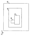
- FIG. 1 shows a schematically simplified representation of a vehicle with a compressed air treatment plant.
- the vehicle 16 is equipped with a compressed air treatment plant 14, which comprises an air dryer 12 with a desiccant cartridge 10 arranged thereon.
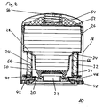
- FIG. 2 shows a first embodiment of a desiccant cartridge according to the invention.
- the desiccant cartridge 10 shown essentially consists of a desiccant 28 filled desiccant box 26, which is arranged in a housing 18.
- the housing 18 is closed at the bottom by a bottom plate 46 with an air inlet 20 and an air outlet 22.
- Between the bottom plate 46 and the desiccant box 26 seal an O-ring 48 and a sealing ring 30 with a rubber lip 42, wherein the rubber lip 42 operates as a check valve.
- the check valve in the form of the rubber lip 42 is mechanically or chemically connected to the desiccant box 26 and has a defined opening and closing characteristics.
- the desiccant box 26 is bounded in the axial direction by a lower air-permeable retaining element 50 and an upper air-permeable retaining element 52 which retain the desiccant 28 inside the desiccant box 26.
- a compression spring 56 and an air-permeable cover 54 are further provided, via which the desiccant 28 is compressed inside the desiccant box 26.
- a combination filter 24 encloses the desiccant box 26 in the axial direction and is radially fixed by a holding element 32 to the desiccant box 26.
- the combination filter 24 divides the desiccant cartridge 10 into a pre-filter area and a post-filter area.
- the purpose of the combination filter 24 during a delivery phase is to hold oil and dirt particles and emulsion droplets on a leading surface, to store liquid oil and to convert the finest oil droplets and aerosols by a coalescence effect in liquid oil and then deposit.
- the design of outflow surface and filter structure causes a defined ratio of air outflow velocity and oil droplet size. This ratio guarantees that no oil droplets get into the desiccant box 24 via the afterfilter area and thus shorten the life of the desiccant cartridge 10 and the connected consumers.
- Air guide elements 34 protrude in the radial direction from the desiccant box 26, starting in the combination filter 24 and thus avoid a bypass of the combination filter 24 by inflowing air.
- the sealing during a delivery phase between pre-filter region and post-filter region is thus achieved by a special Abdichtgeometrie consisting of air guide elements 34 in conjunction with the outer holding member 32.
- the combination filter 24 is wound in the azimuthal direction around the desiccant box 26.
- the filter material of the combination filter 24 forms at least one filter layer in the radial direction.
- the holding element 32 which may be formed, for example, as an elastic rubber sleeve, fixes the filter material of the combination filter 24 in the radial direction.
- the retaining element 32 allows breathing of the combination filter 24 during the deposition of oil and dirt particles within the filter material and protects the combination filter 24 from destruction.
- the filter material of the combination filter 24 directly adjoins the desiccant box 26.
- FIG. 3 shows air flow paths in the first embodiment of a desiccant cartridge according to the invention.
- the desiccant cartridge 10 shown is with the in FIG. 2 identical to the desiccant cartridge shown.
- the sealing ring 30 arranged in the desiccant cartridge 10 comprises a rubber lip 42, which acts as a check valve and allows air to escape from the desiccant cartridge 24, bypassing the combination filter 24.
- the air flow path 58 will be described during a delivery phase indicated on the left side of the desiccant cartridge 10.
- the air enters the desiccant cartridge 10 via the air inlet 20. From there it flows in the radial direction through the combination filter 24, wherein the air guide elements 34 prevent bypassing of the combination filter 24 at the edge of the combination filter 24. simultaneously
- the rubber lip 42 of the sealing ring 30 also blocks a flow around the combination filter 24.
- oil and dirt particles present in the inflowing air are deposited in the interior and on the radial outside of the combination filter 24.
- the air flow path 62 is identical to the air flow path 58, but the flow direction is reversed. Dried and cleaned air flows through the air outlet 22 into the desiccant box 26 and absorbs moisture stored in the desiccant 28. In the region of the combination filter 24, the air flows through the combination filter 24, wherein it blows oil and dirt particles from the filter material and removed through the air inlet 20 from the desiccant cartridge 10.
- the further air flow path 60 is initially identical to the air flow path 62. However, in the post-filter region, both flow paths 60 and 62 separate.
- the oil condensate mixture separated on the outside of the combination filter 24 is flushed from the afterfilter area into the prefilter area, bypassing the combination filter 24. From there, it escapes from the compressed air system by means of a discharge valve located in the air dryer 12. With closed rubber lip 42 of the sealing ring 30, the entire air flow is passed through the combination filter 24 and contaminants are largely removed from this.
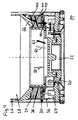
- FIG. 4 shows a section of a second embodiment of a desiccant cartridge according to the invention with air flow paths.
- the illustrated second embodiment of a desiccant cartridge 10 according to the invention differs by the structure of the combination filter 24 of the first embodiment.
- the combination filter 24 builds up in the axial direction stacked circular disc-shaped filter layers 38 which are fixed by a holding device 36 in the axial direction of the desiccant box 26.
- the holding element 36 is first welded or clipped to the desiccant box 26.
- the circular disk-shaped filter layers 38 can then easily to the desiccant box 26 can be stacked or wrapped.
- a plurality of interference contours 40 extending in the axial direction are provided, which extend into the combination filter 24 and prevent a flow around the combination filter 24.
- a coarse filter 64 upstream of the combination filter 24 is provided, which filters out coarser dirt particles from the air stream.
- the illustrated air flows 58, 60, 62 describe the to FIG. 3 analog air flow paths. It should be noted that the combination filter 24 is flowed through axially in this embodiment.
- a sealing ring 30 with a rubber lip 42 ensures a radial seal on the outside of the housing 18th
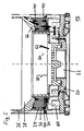
- FIG. 5 shows a section of a third embodiment of a desiccant cartridge according to the invention with air flow paths.
- the illustrated third embodiment of a desiccant cartridge 10 according to the invention differs from the second embodiment by the construction of the combination filter 24.
- the illustrated combination filter 24 is designed as a sintered filter, which is fixed by the holding device 36 in the axial direction of the desiccant box 26.
- the sintered filter may for example be made in one piece, whereby a structure of several filter layers is unnecessary.
- interfering contours 40 are provided, which protrude into the sintering filter and prevent a bypass for bypassing the sintered filter.
- FIG. 6 shows an alternative embodiment of a check valve.
- the illustrated check valve 44 is designed as a discrete sombrero-shaped valve. Several of these individual check valves 44 may be distributed at the edge instead of a single rotating check valve. The individual valves perform the same function as a circumferential rubber lip. In addition, a simple circumferential sealing ring 30 is necessary to seal the pre-filter area from the post-filter area. Also in this embodiment, oil and dirt accumulates in the region of the individual Sombrero valves, which open in a regeneration phase due to the reversing air flow. The backflowing air can then flush out oil and dirt via the sombreroförmigen valves from the desiccant cartridge 10.
- FIG. 7 shows a fourth embodiment of a combination filter with a separate support member which is placed vertically in the desiccant cartridge and flows through in a delivery phase from the inside to the outside.
- the separate support member which is placed vertically in the desiccant cartridge 10, forms a filter element together with the combination filter 24.
- the desiccant cartridge 10 may include both a single, separate filter element and multiple filter elements. These filter elements can be arranged arbitrarily in the desiccant box 26 and can also be used in an air inlet 20 and / or air outlet 22 which is not concentric with the desiccant cartridge 10.
- the combination filter 24 consists of at least one filter layer wound in the azimuthal direction on a separate support element 65, in which the air is passed through at least one air guide element 34 into the combination filter 24.
- the combination filter 24 can be glued to the separate support member 65, but this is not necessary according to the invention.
- a holding element 32, together with the at least one air-guiding element 34, causes no unwanted bypassing of the combination filter 24 to take place during a conveying or a regeneration phase.
- the combination filter 24 is flowed through in the conveying phase from the inside to the outside and the resulting oil droplets can on the outside of the combination filter 24 run off.
- the oil droplets collect with the dirt particles in the region of a rubber lip 42 of a sealing ring 30, which performs the function of a check valve, and are rinsed out in a regeneration phase by the then opened rubber lip 42 from the desiccant cartridge 10.
- the rubber lip 42 protects the combination filter 24 from mechanical overloading during a regeneration phase.
- Other filter materials for the combination filter 24, analogous to the previous embodiments, are also possible, wherein the operation of the combination filter 24 is analogous to the previous embodiments.
- FIG. 8 shows a fifth embodiment of a combination filter with a separate support member which is placed vertically in the desiccant cartridge and flows through in a delivery phase from outside to inside.
- the oil is deposited on the inside of the combination filter 24 and the separate support member 65, respectively.
- the oil droplets can then be rinsed out of the desiccant cartridge 10 through a built-in check valve 44 in a regeneration phase.
- Pre- and post-filter area must be separated by a sealing ring 30, as well as the separate support member 65 must be sealed with the combination filter 24 relative to thezelmittetbereheat 26 with an O-ring 48.
- the operation is otherwise analogous to the previous embodiments.
- FIG. 9 shows some process steps for producing a desiccant cartridge according to the invention with a wound combination filter.
- the illustrated steps refer to the in FIG. 2 described embodiment, but can also be applied to the other wound embodiments be applied.
- FIG. 9 a) the desiccant box 26 is shown without the combination filter.
- one end of the combination filter 24, which is in strip form, is locally fixed to a contact surface. The fixation can be done for example mechanically or by a thin adhesive film. Subsequently, the required filter layers are realized by means of a winding machine by a corresponding number of revolutions. This is in FIG. 9 b) shown.
Landscapes
- Chemical & Material Sciences (AREA)
- Chemical Kinetics & Catalysis (AREA)
- Engineering & Computer Science (AREA)
- Mechanical Engineering (AREA)
- Physics & Mathematics (AREA)
- Analytical Chemistry (AREA)
- Fluid Mechanics (AREA)
- General Engineering & Computer Science (AREA)
- Transportation (AREA)
- Geometry (AREA)
- General Chemical & Material Sciences (AREA)
- Oil, Petroleum & Natural Gas (AREA)
- Drying Of Gases (AREA)
- Valves And Accessory Devices For Braking Systems (AREA)
Description
- Die Erfindung betrifft Trockenmittelpatronen gemäß den Oberbegriffen der unabhängigen Ansprüche 1 und 2.
- Die Erfindung betrifft weiterhin Verfahren zur Herstellung einer Trockenmittelpatrone gemäß den Oberbegriffen der unabhängigen Ansprüche 13 und 14.
- Druckluftaufbereitungsanlagen, die einen Lufttrockner mit einer Trockenmittelpatrone umfassen, werden üblicherweise in Fahrzeugen, zum Beispiel auf der Schiene oder Straße verkehrenden Nutzfahrzeugen, eingesetzt, da diese Teilsysteme, wie druckluftbetriebene Bremsen oder eine Luftfederung, aufweisen, die mit Druckluft versorgt werden müssen. Die von einem Kompressor bereitgestellte Druckluft wird in dem Lufttrockner der Druckluftaufbereitungsanlage von Öl, Schmutz und Feuchtigkeit befreit. Anschließend wird die so aufbereitete Druckluft in geeigneter Weise auf verschiedene vorhandene Verbraucher verteilt. Die Aufbereitung der Druckluft ist notwendig, da die der Druckluftaufbereitungsanlage nachgeordneten Verbraucher ansonsten korrodieren und verschmutzen oder durch die Feuchtigkeit Einfrieren können und schließlich eine deutlich reduzierte Lebensdauer aufweisen würden.
- Die Reinigungsfunktion wird üblicherweise von einer austauschbaren Trockenmittelpatrone, beispielsweise einer Trockenmittelpatrone mit OSC-Funktionalität ("Oil Separator Cartrige"), wahrgenommen, welche Vorrichtungen zum Abscheiden von Öl und Schmutz, üblicherweise ein Koaleszenzfilter, sowie dem Trocknen der Luft umfasst. Damit wird gleichzeitig eine Verunreinigung des verwendeten Trockenmittels durch Öl vermieden, wodurch die Trocknungsleistung beeinträchtigt würde. Ein Rückschlagventil verhindert, dass beim Befüllen die Druckluft das Kombinationsfilter umgehen kann und beim Regenerieren das Kombinationsfilter zu sehr geschädigt wird. Obwohl moderne Druckluftaufbereitungsanlagen eine Möglichkeit zur zumindest teilweisen Regeneration oder Spülung der Trockenmittelpatrone durch Umkehrung der Luftströmung in einem Regenerationszyklus aufweisen, ist die Trockenmittelpatrone ein Verschleißteil, welches regelmäßig ausgetauscht werden muss.
- Zur Schonung der Umwelt, zur Vermeidung von Abfall, und zur Reduzierung der Betriebskosten der Druckluftaufbereitungsanlage ist es daher erstrebenswert, die Konstruktion der Trockenmittelpatrone möglichst einfach zu halten und die Lebensdauer zu verlängern.
- Die
DE 10 2006 019 865 B3 beschreibt eine Trockenmittelpatrone für eine Druckluftaufbereitungsanlage eines Fahrzeugs, wobei die Trockenmittelpatrone ein Koaleszenzfilter als Kombinationsfilter umfasst, welches umlaufend um eine das Trockenmittel aufnehmende Trockenmittelbox angeordnet ist. - Aus der
EP 1 495 934 A2 ist weiterhin eine Trockenmittelpatrone für einen Lufttrockner bekannt, wobei die Trockenmittelpatrone ein Koaleszenzfilter umfasst, das umlaufend um eine Trockenmittelbox oder zwischen der Trockenmittelbox und einer Bodenplatte angeordnet ist. - Eine Trockenmittelpatrone für einen Lufttrockner ist ebenfalls aus der
WO 2004/103509 A2 bekannt, wobei die Trockenmittelpatrone ein Koaleszenzfilter umfasst, das umlaufend um eine Trockenmittelbox angeordnet ist und dabei an seinen Enden von einem die Enden umfassenden Träger abgeschlossen wird. - Die
EP 1 669 125 A1 zeigt eine Trockenmittelpatrone für einen Lufttrockner, wobei die Trockenmittelpatrone ein umlaufend um eine Trockenmittelbox angeordnetes Koaleszenzflter umfasst, welches in einer axialen Richtung der Trockenmittelpatrone in radialer Richtung von einer Fixierung festgelegt ist, welche die Enden des Filters umfasst. - Der Erfindung liegt die Aufgabe zugrunde, eine Trockenmittelpatrone bereitzustellen, die einfacher baut und eine längere Lebensdauer besitzt, wodurch der während des Betriebes der Druckluftaufbereitungsanlage anfallende Abfall sowie die Betriebskosten reduziert werden können.
- Diese Aufgabe wird mit den Merkmalen der unabhängigen Ansprüche gelöst.
- Vorteilhafte Ausführungsformen der Erfindung sind in den abhängigen Ansprüchen gegeben.
- Die Erfindung baut auf der gattungsgemäßen Trockenmittelpatrone gemäß Anspruch 1 dadurch auf, dass an dem Trägerelement in radialer Richtung weisende, das Trägerelement umlaufende Luftleitelemente vorgesehen sind, die die Luft in einer Förderphase in das Innere des Kombinationsfilters leiten, und dass die Luftleitelemente in radialer Richtung in das in radialer Richtung durchströmte Kombinationsfilter hineinragen. Das Halteelement kann beispielsweise als eine elastische Manschette ausgebildet sein, die das Kombinationsfilter sicher an dem Trägerelement fixiert, wobei gleichzeitig das Atmen des Kombinationsfiltermaterials ermöglicht wird, wenn sich in diesem Öl und Schmutz während der Förderphasen ablagert. Das zumindest eine Luftleitelement ermöglicht auf eine Abdichtung zum Trägerelement an den Rändern des Kombinationsfilters zu verzichten, da der Luftstrom in das Kombinationsfiltermaterial geleitet wird und nicht am Rand des Kombinationsfilters vorbeiströmen kann.
Das Kombinationsfilter liegt zumindest abschnittsweise direkt an einem Trägerelement an. Direkt bedeutet einen mechanischen Kontakt der im Wesentlichen ohne weiteres dazwischenliegendes Material, insbesondere ohne Klebstoffe, zwischen dem Kombinationsfilter und dem Trägerelement erfolgt. Durch ein vollständiges direktes Anliegen des Kombinationsfilters an dem Trägerelement kann die Anzahl der Fertigungsschritte beziehungsweise die Fertigungszeit verringert werden, da ein Klebeschritt beziehungsweise eine zugehörige Trocknungszeit für den Klebstoff entfallen kann. Weiterhin wird ein Recycling der Trockenmittelpatrone erleichtert, da keine Klebeverbindung zwischen den Einzelteilen getrennt werden muss. Ist das Anliegen zumindest abschnittsweise direkt, so ist zumindest noch die Menge des benötigten Klebstoffes beziehungsweise des zwischen Filtermaterial und Trägerelement liegenden Materials reduziert. - Alternativ baut die Erfindung auf der gattungsgemäßen Trockenmittelpatrone gemäß Anspruch 2 dadurch auf, dass an dem Trägerelement und der Haltevorrichtung in axialer Richtung weisende das Trägerelement umlaufende Störkonturen vorgesehen sind, welche Luft in das Innere des Kombinationsfilters leiten, und dass die Störkonturen in axialer Richtung in das in axialer Richtung durchströmte Kombinationsfilter hineinragen. Durch das Anbringen der zumindest einen als Luftleitelement wirkenden Störkontur kann ebenfalls auf eine zusätzliche Abdichtung zum Trägerelement am Rand des Kombinationsfilters verzichtet werden. Die axiale Fixierung des Kombinationsfilters gewährleistet die sichere Verpressung des Filtermaterials an dem Trägerelement in axialer Richtung.
- Bevorzugterweise ist vorgesehen, dass ein Teil der Trockenmittelbox als Trägerelement ausgebildet ist. Das zumindest teilweise direkte Anliegen des Kombinationsfilters an der Trockenmittelbox erlaubt die Einsparung von Halte- und Dichtelementen, die üblicherweise das verwendete Filtermaterial des Kombinationsfilters zu einer formstabilen Baugruppe formen. Somit entfällt das bisher übliche separate'Filterelement, welches in der Trockenmittelpatrone eingebaut wurde. Weiterhin wird eine maximale Anströmfläche des Kombinationsfilters ermöglicht, da kein Bereich des Kombinationsfilters von Halte- und Dichtelementen verdeckt wird. Die maximierte Anströmfläche wirkt sich positiv auf die Lebensdauer der Trockenmittelpatrone aus, da eine größere Menge an festen Partikeln und Emulsion gebunden werden kann, ohne den Staudruck wesentlich zu erhöhen. Mit der direkten mechanischen Befestigung des Filtermaterials an einer Haltevorrichtung ist es auch möglich, die Trockenmittelpatrone ohne zusätzlichen Klebstoff zur Fixierung des Filtermaterials, wie ansonsten bei Filterelementen üblich, anzufertigen.
- Alternativ kann vorgesehen sein, dass das Trägerelement separat von der Trockenmittelbox in der Trockenmittelpatrone angeordnet ist. Es ist also ein von der Trockenmittelbox unabhängiges separates Trägerelement in der Trockenmittelpatrone angeordnet. Auch zusammen mit einem separaten Trägerelement können die beschriebenen Fertigungs- und Recyclingvorteile gegenüber einer Klebeverbindung genutzt werden.
- Dabei kann vorgesehen sein, dass der Dichtring auf dem separaten Trägerelement abdichtet. Auf diese Weise kann der Durchmesser des Dichtringes verringert werden, was die Wahrscheinlichkeit für Material- und Montagefehler reduziert.
- Vorteilhafterweise kann vorgesehen sein, dass das Kombinationsfilter in azimutaler Richtung auf das Trägerelement gewickelt ist, wobei die Schichtung der zumindest einen Filterlagen in radialer Richtung erfolgt. Die schichtweise Wicklung des Kombinationsfilters in azimutaler Richtung ist eine einfache Möglichkeit, um das Kombinationsfilter in definierter Weise an dem Trägerelement zu befestigen.
- Nützlicherweise ist dabei vorgesehen, dass das Kombinationsfilter aus zumindest einer das Trägerelement umlaufenden kreisscheibenförmigen Filterlage besteht, wobei die Schichtung der zumindest einen Filterlage in axialer Richtung erfolgt. Die einzelnen Filterlagen können so einfach an dem Trägerelement in der Trockenmittelpatrone oder vor dem Einbau in die Trockenmittelpatrone zu dem Kombinationsfilter zusammengefügt werden, indem die zumindest eine Filterlage auf das Trägerelement geschichtet wird.
- Es ist auch möglich, dass das Kombinationsfilter als reines Koaleszenzfilter ausgebildet ist. Ein reines Koaleszenzfilter besitzt nur eine geringe Speicherfähigkeit. Ein Verschleiß durch Sättigung des Filtermaterials kann auf diese Weise zumindest reduziert werden.
- Es ist weiterhin möglich, dass das Kombinationsfilter ein Sinterfilter ist. Ein Sinterfilter kann in einfacher Weise in der zur Befestigung an dem Trägerelement benötigten Form hergestellt werden.
- Nützlicherweise kann vorgesehen sein, dass eine Gummilippe eines das Trägerelement umlaufenden Dichtrings als Rückschlagventil ausgeführt ist. Das für eine Regeneration notwendige Rückschlagventil ist also als ein das Trägerelement umlaufender Dichtring mit Gummilippe ausgeführt. Auf diese Weise kann die Aufspaltung des Luftstromes in der Regenerationsphase in baulich einfacher Weise realisiert werden, wobei der durch das Rückschlagventil strömende Luftstrom das Kombinationsfilter temporär umgehen kann.
- Alternativ kann vorgesehen sein, dass das Rückschlagventil in Form zumindest dreier separater Einzelventile ausgeführt ist, die zumindest annähernd gleichmäßig über den Umfang des Trägerelements verteilt sind. Die verwendeten Rückschlagventile sind in häufigem Kontakt mit Öl- und Schmutzpartikeln, weshalb separate Einzelventile, insbesondere solche, die aus Metall gefertigt sind, einen geringen Verschleiß aufweisen.
- Die Erfindung baut auf dem gattungsgemäßen Verfahren zur Herstellung einer Trockenmittelpatrone gemäß Anspruch 12 dadurch auf, dass an dem Trägerelement in radialer Richtung weisende, das Trägerelement umlaufende Luftleitelemente angeordnet werden, die die Luft in einer Förderphase in das Innere des Kombinationsfilters leiten und die in radialer Richtung in das in radialer Richtung durchströmte Kombinationsfilter hineinragen.
- Alternativ baut die Erfindung auf dem gattungsgemäßen Verfahren gemäß Anspruch 14 dadurch auf, dass an dem Trägerelement und der Haltevorrichtung in axialer Richtung weisende das Trägerelement umlaufende Störkonturen angeordnet werden, welche Luft in das Innere des Kombinationsfilters leiten und die in axialer Richtung in das in axialer Richtung durchströmte Kombinationsfilter hineinragen.
- Auf diese Weise werden die Vorteile der erfindungsgemäßen Trockenmittelpatronen auch im Rahmen von Verfahren umgesetzt.
- Dieses wird in nützlicher Weise dadurch weiterentwickelt, dass das Kombinationsfilter in azimutaler Richtung auf das Trägerelement gewickelt wird.
- Alternativ kann vorgesehen sein, dass das Kombinationsfilter aus zumindest einer kreisscheibenförmigen Filterlage aufgebaut wird, die das Trägerelement umläuft.
- Die Erfindung wird nun mit Bezug auf die begleitenden Zeichnungen anhand besonders bevorzugter Ausführungsformen beispielhaft erläutert.
- Es zeigen:
- Figur 1
- eine schematisch vereinfachte Darstellung eines Fahrzeugs mit einer Druckluftaufbereitungsanlage;
- Figur 2
- eine erste Ausführungsform einer erfindungsgemäßen Trockenmittelpatrone;
- Figur 3
- Luftströmungswege in der ersten Ausführungsform einer erfindungsgemäßen Trockenmittelpatrone;
- Figur 4
- einen Ausschnitt einer zweiten Ausführungsform einer erfindungsgemäßen Trockenmittelpatrone mit Luftströmungswegen;
- Figur 5
- einen Ausschnitt einer dritten Ausführungsform einer erfindungsgemäßen Trockenmittelpatrone mit Luftströmungswegen;
- Figur 6
- eine alternative Ausgestaltung eines Rückschlagventils;
- Figur 7
- eine vierte Ausführungsform eines Kombinationsfitters mit einem separaten Trägerelement, welches senkrecht in der Trockenmittelpatrone platziert und in einer Förderphase von innen nach außen durchströmt wird;
- Figur8
- eine fünfte Ausführungsform eines Kombinationsfilters mit einem separaten Trägerelement, welches senkrecht in der Trockenmittelpatrone platziert und in einer Förderphase von außen nach innen durchströmt wird und
- Figur 9
- einige Prozessschritte zur Herstellung einer erfindungsgemäßen Trockenmittelpatrone mit einem gewickelten Kombinationsfilter.
- In den nachfolgenden Zeichnungen bezeichnen gleiche Bezugszeichen gleiche oder gleichartige Teile.
-
Figur 1 zeigt eine schematisch vereinfachte Darstellung eines Fahrzeugs mit einer Druckluftaufbereitungsanlage. Das Fahrzeug 16 ist mit einer Druckluftaufbereitungsanlage 14 ausgerüstet, die einen Lufttrockner 12 mit einer daran angeordneten Trockenmittelpatrone 10 umfasst. -
Figur 2 zeigt eine erste Ausführungsform einer erfindungsgemäßen Trockenmittelpatrone. Die dargestellte Trockenmittelpatrone 10 besteht im Wesentlichen aus einer mit einem Trockenmittel 28 gefüllten Trockenmittelbox 26, die in einem Gehäuse 18 angeordnet ist. Das Gehäuse 18 wird im unteren Bereich von einer Bodenplatte 46 mit einem Lufteinlass 20 und einem Luftauslass 22 verschlossen. Zwischen der Bodenplatte 46 und der Trockenmittelbox 26 dichten ein O-Ring 48 und einem Dichtring 30 mit einer Gummilippe 42, wobei die Gummilippe 42 als ein Rückschlagventil arbeitet. Das Rückschlagventil in Form der Gummilippe 42 ist mechanisch oder chemisch mit der Trockenmittelbox 26 verbunden und weist eine definierte Öffnungs- und Schließcharakteristik auf. Insbesondere Öffnet das Rückschlagventil bei einem Überdruck in der Trockenmittelpatrone 10 und wirkt somit als Sicherheitsventil. Die Trockenmittelbox 26 ist in axialer Richtung von einem unteren luftdurchlässigen Rückhalteelement 50 und einem oberen luftdurchlässigen Rückhalteelement 52 begrenzt, die das Trockenmittel 28 im Inneren der Trockenmittelbox 26 zurückhalten. Im oberen Bereich der Trockenmittelbox 26 ist weiterhin eine Druckfeder 56 und ein luftdurchlässiger Deckel 54 vorgesehen, über die das Trockenmittel 28 im Inneren der Trockenmittelbox 26 komprimiert wird. Ein Kombinationsfilter 24 umschließt in axialer Richtung die Trockenmittelbox 26 und wird radial von einem Halteelement 32 an der Trockenmittelbox 26 fixiert. Das Kombinationsfilter 24 unterteilt die Trockenmittelpatrone 10 in einen Vorfilterbereich und einen Nachfilterbereich. Aufgabe des Kombinationsfilters 24 während einer Förderphase ist es, Öl- und Schmutzpartikel sowie Emulsionströpfchen an einer Anströmfläche festzuhalten, flüssiges Öl zu speichern und feinste Öltröpfchen und Aerosole durch einen Koaleszenzeffekt in flüssiges Öl umzuwandeln und daraufhin abzuscheiden. Die Auslegung von Ausströmfläche und Filteraufbau bewirkt dabei ein definiertes Verhältnis von Luftausströmgeschwindigkeit und Öltröpfchengröße. Dieses Verhältnis garantiert, dass keine Öltröpfchen über den Nachfilterbereich in die Trockenmittelbox 24 gelangen und so die Lebensdauer der Trockenmittelpatrone 10 und der angeschlossenen Verbraucher verkürzen. Luftleitelemente 34 ragen in radialer Richtung von der Trockenmittelbox 26 ausgehend in das Kombinationsfilter 24 hinein und vermeiden so eine Umgehung des Kombinationsfilters 24 durch einströmende Luft. Die Abdichtung während einer Förderphase zwischen Vorfilterbereich und Nachfilterbereich wird also durch eine spezielle Abdichtgeometrie bestehend aus Luftleitelementen 34 in Verbindung mit dem außen liegenden Halteelement 32 erreicht. - Der Kombinationsfilter 24 wird in azimutaler Richtung um die Trockenmittelbox 26 gewickelt. Dabei bildet das Filtermaterial des Kombinationsfilters 24 zumindest eine Filterschicht in radialer Richtung. Das Halteelement 32, das beispielsweise als elastische Gummimanschette ausgebildet sein kann, fixiert das Filtermaterial des Kombinationsfilters 24 in radialer Richtung. Gleichzeitig erlaubt das Halteelement 32 ein Atmen des Kombinationsfilters 24 während der Ablagerung von Öl- und Schmutzpartikeln innerhalb des Filtermaterials und schützt das Kombinationsfilter 24 vor Zerstörung. Das Filtermaterial des Kombinationsfilters 24 grenzt direkt an die Trockenmittelbox 26.
-
Figur 3 zeigt Luftströmungswege in der ersten Ausführungsform einer erfindungsgemäßen Trockenmittelpatrone. Die dargestellte Trockenmittelpatrone 10 ist mit der inFigur 2 dargestellten Trockenmittelpatrone identisch. Auf der linken Seite der Trockenmittelpatrone 10 ist ein Luftströmungsweg 58 während einer Förderphase eingezeichnet. Auf der rechten Seite der Trockenmittelpatrone 10 sind die beiden möglichen Luftströmungswege 60, 62 während einer Regenerationsphase eingezeichnet. Der in der Trockenmittelpatrone 10 angeordnete Dichtring 30 umfasst eine Gummilippe 42, die als Rückschlagventil wirkt und Luft unter Umgehung des Kombinationsfilters 24 aus der Trockenmittelpatrone 24 entweichen lässt. - Zunächst wird der Luftströmungsweg 58 während einer Förderphase beschrieben, die auf der linken Seite der Trockenmittelpatrone 10 eingezeichnet ist. Die Luft tritt über den Lufteinlass 20 in die Trockenmittelpatrone 10 ein. Von dort aus strömt sie in radialer Richtung durch das Kombinationsfilter 24 hindurch, wobei die Luftleitelemente 34 eine Umgehung des Kombinationsfilters 24 am Rand des Kombinationsfilters 24 verhindern. Gleichzeitig blockiert auch die Gummilippe 42 des Dichtrings 30 eine Umströmung des Kombinationsfilters 24. Während des Durchtritts durch das Kombinationsfilter 24 lagern sich in der einströmenden Luft vorhandene Öl- und Schmutzpartikel im Inneren und an der radialen Außenseite des Kombinationsfilters 24 ab. Diese Ablagerungen Vergrößern sich während des Förderbetriebs und können durch die Schwerkraft ab einer gewissen Größe in axialer Richtung an der radialen Außenseite des Kombinationsfilters 24 ablaufen und sich im Bereich der Gummilippe 42 sammeln. Die von Öl- und Schmutzpartikeln gereinigte Luft strömt anschließend zwischen der Trockenmittelbox 26 und dem Gehäuse 18 der Trockenmittelpatrone 10 in axialer Richtung aufwärts. Im Bereich des oberen luftdurchlässigen Rückhalteelements 52 erfolgt eine Umlenkung der Luft, die anschließend in die Trockenmittelbox 26 einströmt und dort durch das Trockenmittel 28 getrocknet wird. Danach verlässt die gereinigte und getrocknete Luft die Trockenmittelpatrone 10 durch den Luftauslass 22.
- Während einer Regenerationsphase existieren zwei mögliche Luftströmungswege 60, 62. Der Luftströmungsweg 62 ist identisch mit dem Luftströmungsweg 58, wobei jedoch die Strömungsrichtung umgekehrt ist. Getrocknete und gereinigte Luft strömt durch den Luftauslass 22 in die Trockenmittelbox 26 ein und nimmt in dem Trockenmittel 28 gespeicherte Feuchtigkeit auf. Im Bereich des Kombinationsfilters 24 strömt die Luft durch das Kombinationsfilter 24 hindurch, wobei sie Öl- und Schmutzpartikel aus dem Filtermaterial ausbläst und durch den Lufteinlass 20 aus der Trockenmittelpatrone 10 entfernt. Der weitere Luftströmungsweg 60 ist zunächst identisch mit dem Luftströmungsweg 62. Im Nachfilterbereich trennen sich jedoch beide Strömungswege 60 und 62. Aufgrund der geänderten Druckverhältnisse kann ein Teil der Luft das Kombinationsfilter 24 über die nun geöffnete Gummilippe 42 umgehen, wobei im Bereich der Gummilippe 42 abgelagerte Öl- und Schmutzpartikel mitgerissen und aus der Trockenmittelpatrone 10 ausgespült werden. Die Abdichtung im Regenerationsvorgang zwischen Nachfilterbereich und Vorfilterbereich erfolgt ebenfalls durch die Abdichtgeometrie und die Verpressung durch das Halteelement 32. Im Gegensatz zur Förderphase öffnet die Gummilippe 42 des Dichtrings 30 anfangs bei den zuerst auftretenden höheren Druckdifferenzen und schließt danach bei Erreichen eines definierten geringeren Differenzdrucks. Nützlicherweise wird dadurch auch das Kombinationsfilter 24 vor mechanischer Überlastung während einer Regenerationsphase geschützt. Während der Öffnungsphase der Gummilippe 42 des Dichtringes 30 wird das an der Außenseite des Kombinationsfilters 24 abgeschiedene Öl-Kondensatgemisch unter Umgehung des Kombinationsfilters 24 vom Nachfilterbereich in den Vorfilterbereich gespült. Von dort entweicht es durch ein im Lufttrockner 12 befindliches Ablassventil aus dem Druckluftsystem. Bei geschlossener Gummilippe 42 des Dichtrings 30 wird der gesamte Luftstrom durch das Kombinationsfilter 24 geleitet und Verschmutzungen werden weitestgehend aus diesem entfernt.
-
Figur 4 zeigt einen Ausschnitt einer zweiten Ausführungsform einer erfindungsgemäßen Trockenmittelpatrone mit Luftströmungswegen. Die dargestellte zweite Ausführungsform einer erfindungsgemäßen Trockenmittelpatrone 10 unterscheidet sich durch den Aufbau des Kombinationsfilters 24 von der ersten Ausführungsform. Bei dieser zweiten Ausführungsform baut sich das Kombinationsfilter 24 aus in axialer Richtung gestapelten kreisscheibenförmigen Filterlagen 38 auf, die von einer Haltevorrichtung 36 in axialer Richtung an der Trockenmittelbox 26 fixiert werden. Das Halteelement 36 wird dazu zunächst an der Trockenmittelbox 26 angeschweißt oder verclipst. Die kreisscheibenförmigen Filterlagen 38 können dann einfach an die Trockenmittelbox 26 gestapelt oder gewickelt werden. Weiterhin sind mehrere sich in axialer Richtung erstreckende Störkonturen 40 vorgesehen, die in das Kombinationsfilter 24 hineinreichen und eine Umströmung des Kombinationsfilters 24 verhindern. Ferner ist ein dem Kombinationsfilter 24 strömungstechnisch vorgelagerter Grobfilter 64 vorgesehen, der gröbere Schmutzpartikel aus dem Luftstrom ausfiltert. Die dargestellten Luftströmungen 58, 60, 62 beschreiben die zuFigur 3 analogen Luftströmungswege. Dabei ist zu beachten, dass das Kombinationsfilter 24 bei dieser Ausführungsform axial durchströmt wird. Ein Dichtring 30 mit einer Gummilippe 42 sorgt dabei für eine radiale Abdichtung außen am Gehäuse 18. -
Figur 5 zeigt einen Ausschnitt einer dritten Ausführungsform einer erfindungsgemäßen Trockenmittelpatrone mit Luftströmungswegen. Die dargestellte dritte Ausführungsform einer erfindungsgemäßen Trockenmittelpatrone 10 unterscheidet sich von der zweiten Ausführungsform durch den Aufbau des Kombinationsfilters 24. Das dargestellte Kombinationsfilter 24 ist als Sinterfilter ausgeführt, das von der Haltevorrichtung 36 in axialer Richtung an der Trockenmittelbox 26 fixiert wird. Das Sinterfilter kann beispielsweise einstückig hergestellt sein, wodurch ein Aufbau aus mehreren Filterschichten überflüssig wird. Auch bei dieser Ausführungsform sind Störkonturen 40 vorgesehen, die in das Sinterfilter hineinragen und einen Bypass zur Umgehung des Sinterfilters verhindern. -
Figur 6 zeigt eine alternative Ausgestaltung eines Rückschlagsventils. Das dargestellte Rückschlagventil 44 ist als diskretes sombreroförmiges Ventil ausgeführt. Mehrere dieser einzelnen Rückschlagventile 44 können anstatt eines einzelnen umlaufenden Rückschlagventils am Rand verteilt werden. Die Einzelventile erfüllen die gleiche Funktion wie eine umlaufende Gummilippe. Zusätzlich ist ein einfacher, umlaufender Dichtring 30 notwendig, um den Vorfilterbereich gegenüber dem Nachfilterbereich abzudichten. Auch bei dieser Ausführungsform sammelt sich Öl und Schmutz im Bereich der einzelnen Sombreroventile, die in einer Regenerationsphase aufgrund der sich umkehrenden Luftströmung öffnen. Die rückströmende Luft kann dann Öl und Schmutz über die sombreroförmigen Ventile aus der Trockenmittelpatrone 10 ausspülen. -
Figur 7 zeigt eine vierte Ausführungsform eines Kombinationsfilters mit einem separaten Trägerelement, welches senkrecht in der Trockenmittelpatrone platziert und in einer Förderphase von innen nach außen durchströmt wird. Das separate Trägerelement, das senkrecht in der Trockenmittelpatrone 10 platziert ist, bildet zusammen mit dem Kombinationsfilter 24 ein Filterelement. Die Trockenmittelpatrone 10 kann sowohl ein einzelnes, separates Filterelement als auch mehrere Filterelemente beinhalten. Diese Filterelemente können beliebig in der Trockenmittelbox 26 angeordnet und auch bei einem nicht konzentrisch zur Trockenmittelpatrone 10 angeordneten Lufteinlass 20 und/oder Luftauslass 22 verwendet werden. Das Kombinationsfilter 24 besteht aus mindestens einer in azimutaler Richtung auf ein separates Trägerelement 65 gewickelten Filterlage, bei der die Luft durch mindestens ein Luftleitelement 34 in das Kombinationsfilter 24 geleitet wird. Zusätzlich kann das Kombinationsfilter 24 auch mit dem separaten Trägerelement 65 verklebt werden, wobei dies jedoch erfindungsgemäß nicht notwendig ist. Ein Haltelement 32 bewirkt zusammen mit dem mindestens einen Luftleitelement 34, dass während einer Förder- oder einer Regenerationsphase keine unerwünschte Umgehung des Kombinationsfilters 24 stattfindet. In dieser Ausführungsform wird das Kombinationsfilter 24 in der Förderphase von innen nach außen durchströmt und die entstehenden Öltröpfchen können an der Außenseite des Kombinationsfilters 24 ablaufen. Die Öltröpfchen sammeln sich mit den Schmutzpartikeln im Bereich einer Gummilippe 42 eines Dichtrings 30, die die Funktion eines Rückschlagventils übernimmt, und werden in einer Regenerationsphase durch die dann geöffnete Gummilippe 42 aus der Trockenmittelpatrone 10 ausgespült. Die Gummilippe 42 schützt dabei das Kombinationsfilter 24 vor einer mechanischen Überbelastung während einer Regenerationsphase. Andere Filtermaterialien für das Kombinationsfilter 24, analog zu den vorhergehenden Ausführungsformen, sind ebenfalls möglich, wobei die Funktionsweise des Kombinationsfilters 24 zu den vorhergehenden Ausführungsformen analog ist. -
Figur 8 zeigt eine fünfte Ausführungsform eines Kombinationsfilters mit einem separaten Trägerelement, welches senkrecht in der Trockenmittelpatrone platziert und in einer Förderphase von außen nach innen durchströmt wird. Somit wird das Öl an der Innenseite des Kombinationsfilters 24 beziehungsweise des separaten Trägerelements 65 abgeschieden. Die Öltröpfchen können dann in einer Regenerationsphase durch ein integriertes Rückschlagventil 44 aus der Trockenmittelpatrone 10 gespült werden. Vor- und Nachfilterbereich müssen durch einen Dichtring 30 voneinander getrennt werden, ebenso muss das separate Trägerelement 65 mit dem Kombinationsfilter 24 gegenüber dem Trockenmittetbehätter 26 mit einem O-Ring 48 abgedichtet werden. Die Funktionsweise ist ansonsten zu den vorhergehenden Ausführungsformen analog. -
Figur 9 zeigt einige Prozessschritte zur Herstellung einer erfindungsgemäßen Trockenmittelpatrone mit einem gewickelten Kombinationsfilter. Die dargestellten Schritte beziehen sich auf die inFigur 2 beschriebene Ausführungsform, können jedoch auch auf die anderen gewickelten Ausführungsformen angewendet werden. InFigur 9 a) ist die Trockenmittelbox 26 ohne das Kombinationsfilter dargestellt. An der Trockenmittelbox 26 wird an einer Anlagefläche ein Ende des Kombinationsfilters 24, der in Streifenform vorliegt, lokal fixiert. Die Fixierung kann beispielsweise mechanisch oder durch einen dünnen Klebefilm erfolgen. Anschließend werden mithilfe einer Wickelmaschine die benötigten Filterlagen durch eine entsprechende Anzahl von Umdrehungen realisiert. Dies ist inFigur 9 b) dargestellt. Bei unmittelbarer Befestigung des Halteelements 32 nach dem Wickelprozess kann eine temporäre beziehungsweise weitere dauerhafte Fixierung des Kombinationsfilters 24 an der Trockenmittelbox entfallen. Die Fixierung durch das Halteelement ist inFigur 9 c) dargestellt. Die weiteren nicht dargestellten Prozessschritte entsprechen dem Stand der Technik und sind dem Fachmann geläufig. - Die in der vorstehenden Beschreibung, in den Zeichnungen sowie in den Ansprüchen offenbarten Merkmale der Erfindung können sowohl einzeln als auch in beliebiger Kombination für die Verwirklichung der Erfindung wesentlich sein.
Bezugszeichenliste 10 Trockenmittelpatrone 12 Lufttrockner 14 Druckluftaufbereitungsanlage 16 Fahrzeug 18 Gehäuse 20 Lufteinlass 22 Luftauslass 24 Kombinationsfilter 26 Trockenmittelbox 28 Trockenmittel 30 Dichtring 32 Halteelement 34 Luftleitelement 36 Haltevorrichtung 38 Filterlage 40 Störkontur 42 Gummilippe 44 Rückschlagventil 46 Bodenplatte 48 O-Ring 50 unteres luftdurchlässiges Rückhalteelement 52 oberes luftdurchlässiges Rückhalteelement 54 luftdurchlässiger Deckel 56 Druckfeder 58 Luftströmungsweg Förderphase 60 weiterer Luftströmungsweg Regenerationsphase 62 Luftströmungsweg Regenerationsphase 64 Grobfilter 65 separates Trägerelement 66 Trägerelement
Claims (15)
- Trockenmittelpatrone (10) für einen Lufttrockner (12) einer Druckluftaufbereitungsanlage (14) eines Fahrzeugs (16) mit- einem Gehäuse (18) mit einem Lufteinlass (20) und einem Luftauslass (22),- einem Kombinationsfilter (24) aus zumindest einer Filterlage zur Abscheidung von Öl- und Schmutzpartikeln,- einer Trockenmittelbox (26) mit Trockenmittel (28) zum Trocknen der Luft und- einem Rückschlagventil (42, 44), über das während einer Regenerationsphase zumindest ein Teil des zur Regeneration verwendeten Luftstromes an dem Kombinationsfilter (24) vorbeiströmen kann,- wobei das Kombinationsfilter (24) zumindest abschnittsweise direkt an einem Trägerelement (65, 66) anliegt, und- wobei ein Halteelement (32) vorgesehen ist, dass das Kombinationsfilter (24) in radialer Richtung an dem Trägerelement (65, 66) fixiert,
dadurch gekennzeichnet,- dass an dem Trägerelement (65, 66) in radialer Richtung weisende, das Trägerelement (65, 66) umlaufende Luftleitelemente (34) vorgesehen sind, die die Luft in einer Förderphase in das Innere des Kombinationsfilters (24) leiten, und- dass die Luftleitelemente (34) in radialer Richtung in das in radialer Richtung durchströmte Kombinationsfilter (24) hineinragen. - Trockenmittelpatrone (10) für einen Lufttrockner (12) einer Druckluftaufbereitungsanlage (14) eines Fahrzeugs (16) mit- einem Gehäuse (18) mit einem Lufteinlass (20) und einem Luftauslass (22),- einem Kombinationsfilter (24) aus zumindest einer Filterlage zur Abscheidung von Öl- und Schmutzpartikeln,- einer Trockenmittelbox (26) mit Trockenmittel (28) zum Trocknen der Luft und- einem Rückschlagventil (42, 44), über das während einer Regenerationsphase zumindest ein Teil des zur Regeneration verwendeten Luftstromes an dem Kombinationsfilter (24) vorbeiströmen kann,- wobei das Kombinationsfilter (24) zumindest abschnittsweise direkt an einem Trägerelement (65, 66) anliegt, und- wobei eine Haltevorrichtung (36) vorgesehen ist, dass das Kombinationsfilter (24) in axialer Richtung fixiert,
dadurch gekennzeichnet,- dass an dem Trägerelement (65, 66) und der Haltevorrichtung (36) in axialer Richtung weisende das Trägerelement (65, 66) umlaufende Störkonturen (40) vorgesehen sind, welche Luft in das Innere des Kombinationsfilters (24) leiten, und- dass die Störkonturen (40) in axialer Richtung in das in axialer Richtung durchströmte Kombinationsfilter (24) hineinragen. - Trockenmittelpatrone (10) nach Anspruch 1 oder 2, dadurch gekennzeichnet, dass ein Teil der Trockenmittelbox (26) als Trägerelement (66) ausgebildet ist.
- Trockenmittelpatrone (10) nach Anspruch 1 oder 2, dadurch gekennzeichnet, dass das Trägerelement (65) separat von der Trockenmittelbox (26) in der Trockenmittelpatrone (10) angeordnet ist.
- Trockenmittelpatrone (10) nach Anspruch 4, dadurch gekennzeichnet, dass der Dichtring (30) auf dem separaten Trägerelement (65) abdichtet.
- Trockenmittelpatrone (10) nach Anspruch 1, dadurch gekennzeichnet, dass das Kombinationsfilter (24) in azimutaler Richtung auf das Trägerelement (65, 66) gewickelt ist, wobei die Schichtung der zumindest einen Filterlage in radialer Richtung erfolgt.
- Trockenmittelpatrone (10) nach Anspruch 2, dadurch gekennzeichnet, dass das Kombinationsfilter (24) aus zumindest einer das Trägerelement (65, 66) umlaufenden kreisscheibenförmigen Filterlage (38) besteht, wobei die Schichtung der zumindest einen Filterlage (38) in axialer Richtung erfolgt.
- Trockenmittelpatrone (10) nach Anspruch 2, dadurch gekennzeichnet, dass das Kombinationsfilter (24) als reines Koaleszenzfilter ausgebildet ist.
- Trockenmittelpatrone (10) nach Anspruch 2 oder 8, dadurch gekennzeichnet, dass das Kombinationsfilter (24) ein Sinterfilter ist.
- Trockenmittelpatrone (10) nach einem der vorhergehenden Ansprüche, dadurch gekennzeichnet, dass eine Gummilippe (42) eines das Trägerelement (65, 66) umlaufenden Dichtrings (30) als Rückschlagventil ausgeführt ist.
- Trockenmittelpatrone (10) nach einem der Ansprüche 1 bis 9, dadurch gekennzeichnet, dass das Rückschlagventil (44) in Form zumindest dreier separater Einzelventile ausgeführt ist, die gleichmäßig über den Umfang des Trägerelements (65, 66) verteilt sind.
- Verfahren zur Herstellung einer Trockenmittelpatrone (10) für einen Lufttrockner (12) einer Druckluftaufbereitungsanlage (14) eines Fahrzeugs (16) mit- einem Gehäuse (18) mit einem Lufteinlass (20) und einem Luftauslass (22),- einem Kombinationsfilter (24) zur Abscheidung von Öl- und Schmutzpartikeln,- einer Trockenmittelbox (26) mit Trockenmittel (28) zum Trocknen der Luft und- einem Rückschlagventil (42, 44), über das während einer Regenerationsphase zumindest ein Teil des zur Regeneration verwendeten Luftstromes an dem Kombinationsfilter (24) vorbeiströmen kann,- wobei das Kombinationsfilter (24) direkt an einem Trägerelement (65, 66) befestigt wird, und- wobei das Kombinationsfilter (24) in radialer Richtung an dem Trägerelement (65, 66) fixiert wird,
dadurch gekennzeichnet,- dass an dem Trägerelement (65, 66) in radialer Richtung weisende, das Trägerelement (65, 66) umlaufende Luftleitelemente (34) angeordnet werden, die die Luft in einer Förderphase in das Innere des Kombinationsfilters (24) leiten und die in radialer Richtung in das in radialer Richtung durchströmte Kombinationsfilter (24) hineinragen. - Verfahren zur Herstellung einer Trockenmittelpatrone (10) für einen Lufttrockner (12) einer Druckluftaufbereitungsanlage (14) eines Fahrzeugs (16) mit- einem Gehäuse (18) mit einem Lufteinlass (20) und einem Luftauslass (22),- einem Kombinationsfilter (24) zur Abscheidung von Öl- und Schmutzpartikeln,- einer Trockenmittelbox (26) mit Trockenmittel (28) zum Trocknen der Luft und- einem Rückschlagventil (42, 44), über das während einer Regenerationsphase zumindest ein Teil des zur Regeneration verwendeten Luftstromes an dem Kombinationsfilter (24) vorbeiströmen kann,- wobei das Kombinationsfilter (24) direkt an einem Trägerelement (65, 66) befestigt wird, und- wobei das Kombinationsfilter (24) in axialer Richtung an dem Trägerelement (65, 66) fixiert wird,dadurch gekennzeichnet, dass an dem Trägerelement (65, 66) und der Haltvorrichtung (36) in axialer Richtung weisende das Trägerelement (65, 66) umlaufende Störkonturen (40) angeordnet werden, welche Luft in das Innere des Kombinationsfilters (24) leiten und die in axialer Richtung in das in axialer Richtung durchströmte Kombinationsfilter (24) hineinragen.
- Verfahren nach Anspruch 12, dadurch gekennzeichnet,- dass das Kombinationsfilter (24) in azimutaler Richtung auf das Trägerelement (65, 66) gewickelt wird.
- Verfahren nach Anspruch 13, dadurch gekennzeichnet,- dass das Kombinationsfilter (24) aus zumindest einer kreisscheibenförmigen Filterlage (38) aufgebaut wird, die das Trägerelement (65, 66) umläuft.
Applications Claiming Priority (2)
| Application Number | Priority Date | Filing Date | Title |
|---|---|---|---|
| DE102007046167.6A DE102007046167B4 (de) | 2007-09-27 | 2007-09-27 | Luftfilterpatrone für eine Druckluftaufbereitungsanlage |
| PCT/EP2008/007390 WO2009043427A1 (de) | 2007-09-27 | 2008-09-10 | Trockenmittelpatrone für eine druckluftaufbereitungsanlage und verfahren zur herstellung einer trockenmittelpatrone |
Publications (2)
| Publication Number | Publication Date |
|---|---|
| EP2192970A1 EP2192970A1 (de) | 2010-06-09 |
| EP2192970B1 true EP2192970B1 (de) | 2013-07-10 |
Family
ID=40083698
Family Applications (2)
| Application Number | Title | Priority Date | Filing Date |
|---|---|---|---|
| EP08801962.5A Not-in-force EP2192970B1 (de) | 2007-09-27 | 2008-09-10 | Trockenmittelpatrone für eine druckluftaufbereitungsanlage und verfahren zur herstellung einer trockenmittelpatrone |
| EP08801963.3A Active EP2192971B1 (de) | 2007-09-27 | 2008-09-10 | Luftfilterpatrone für eine druckluftaufbereitungsanlage mit entnehmbarer trockenmittelbox |
Family Applications After (1)
| Application Number | Title | Priority Date | Filing Date |
|---|---|---|---|
| EP08801963.3A Active EP2192971B1 (de) | 2007-09-27 | 2008-09-10 | Luftfilterpatrone für eine druckluftaufbereitungsanlage mit entnehmbarer trockenmittelbox |
Country Status (3)
| Country | Link |
|---|---|
| EP (2) | EP2192970B1 (de) |
| DE (1) | DE102007046167B4 (de) |
| WO (2) | WO2009043428A1 (de) |
Families Citing this family (19)
| Publication number | Priority date | Publication date | Assignee | Title |
|---|---|---|---|---|
| DE102009052786B4 (de) * | 2009-11-11 | 2021-10-21 | Knorr-Bremse Systeme für Nutzfahrzeuge GmbH | Luftaufbereitungsanlage |
| DE102009052785B4 (de) * | 2009-11-11 | 2013-02-07 | Knorr-Bremse Systeme für Nutzfahrzeuge GmbH | Trockenmittelpatrone und Luftaufbereitungsanlage mit Trockenmittelpatrone |
| DE102010010882B4 (de) * | 2010-03-10 | 2021-10-21 | Knorr-Bremse Systeme für Nutzfahrzeuge GmbH | Lufttrocknerpatrone und Verfahren zum Betreiben einer Lufttrocknerpatrone |
| DE102010011956A1 (de) * | 2010-03-18 | 2011-09-22 | Mann + Hummel Gmbh | Lufttrockner, insbesondere in einer Druckluftanlage in einem Nutzfahrzeug |
| DE102010024889B4 (de) | 2010-06-24 | 2014-12-11 | Wabco Gmbh | Luftversorgungseinrichtung für ein Fahrzeug mit pneumatischen Einrichtungen |
| TR201107171A2 (tr) * | 2011-07-20 | 2012-12-21 | Asaş Fi̇ltre Sanayi̇ Ve Ti̇caret Anoni̇m Şi̇rketi̇ | Bir hava kurutucu filtre. |
| DE102011109002A1 (de) | 2011-07-29 | 2013-01-31 | Wabco Gmbh | Dichtring mit gesonderter Haltekontur |
| DE102011116520A1 (de) * | 2011-10-20 | 2013-04-25 | Knorr-Bremse Systeme für Nutzfahrzeuge GmbH | Luftfilterpatrone zur Druckluftaufbereitung für eine Druckluftaufbereitungsanlage |
| DE102012005308B4 (de) * | 2011-12-23 | 2022-03-17 | Wabco Gmbh | Druckluftversorgungsanlage, Druckluftversorgungssystem und Fahrzeug, insbesondere PKW, mit einer Druckluftversorgungsanlage |
| DE102013210571A1 (de) * | 2013-06-06 | 2014-12-11 | Mahle International Gmbh | Kraftstofftanksystem für ein Kraftfahrzeug |
| DE102014116804A1 (de) * | 2014-11-17 | 2016-05-19 | Knorr-Bremse Systeme für Nutzfahrzeuge GmbH | Trockenmittelpatrone |
| DE102015117283A1 (de) * | 2015-10-09 | 2017-04-13 | Knorr-Bremse Systeme für Nutzfahrzeuge GmbH | Trockenmittelpatrone mit verbesserter Trocknung und Regeneration |
| DE102015122168A1 (de) | 2015-12-18 | 2017-06-22 | Knorr-Bremse Systeme für Nutzfahrzeuge GmbH | Lufttrocknerpatrone |
| DE102016120477A1 (de) * | 2016-10-27 | 2018-05-03 | Knorr-Bremse Systeme für Nutzfahrzeuge GmbH | Lufttrocknerpatrone |
| DE102018208746B4 (de) | 2018-06-04 | 2020-07-02 | Glatt Gmbh | An einer Prozessapparatur angeordnete Filtervorrichtung zum Entstauben von Prozessluft der Prozessapparatur |
| KR102438981B1 (ko) * | 2021-11-22 | 2022-09-01 | 주식회사 세명테크 | 상용차용 공기 건조기 카트리지의 프리 필터 홀더 및 이를 포함하는 공기 건조기 카트리지 |
| KR102688043B1 (ko) * | 2023-09-08 | 2024-07-24 | 박상선 | 에어 드라이어 필터 어셈블리 |
| CN117128216B (zh) * | 2023-10-27 | 2023-12-19 | 广州唯友斯工程机械配件有限公司 | 一种港口门座式起重机旋转装置的废油回收装置 |
| CN118224159B (zh) * | 2024-05-24 | 2024-09-13 | 南通奔腾精密机器有限公司 | 一种双行程胀缩油缸 |
Family Cites Families (10)
| Publication number | Priority date | Publication date | Assignee | Title |
|---|---|---|---|---|
| DE8518993U1 (de) * | 1985-06-29 | 1986-10-30 | Robert Bosch Gmbh, 7000 Stuttgart | Lufttrockner für Druckluftanlagen |
| DE3603043A1 (de) * | 1986-01-31 | 1987-08-06 | Knorr Bremse Ag | Trocknungspatrone fuer lufttrocknungsanlagen, insbesondere fuer druckluftbremsanlagen von fahrzeugen |
| DE4339758A1 (de) * | 1993-11-22 | 1995-05-24 | Knorr Bremse Systeme | Trocknungspatrone für Lufttrocknungsanlagen, insbesondere für Druckluftbremsanlagen von Fahrzeugen |
| DE29808779U1 (de) * | 1998-05-15 | 1998-07-16 | Festo AG & Co, 73734 Esslingen | Filtergerät |
| EP1048541A1 (de) * | 1999-04-28 | 2000-11-02 | Baldwin Filters, Inc. | Lufttrocknungskanister |
| DE19955898A1 (de) * | 1999-11-20 | 2001-05-23 | Mann & Hummel Filter | Trockenmittelbox |
| BRPI0410766A (pt) * | 2003-05-19 | 2006-06-27 | Wabco Automotive Uk Ltd | cartucho de secador de ar |
| DE10329401B4 (de) * | 2003-06-30 | 2016-02-11 | Knorr-Bremse Systeme für Nutzfahrzeuge GmbH | Lufttrockner |
| DE102004059508C5 (de) * | 2004-12-10 | 2008-07-03 | Haldex Brake Products Gmbh | Verfahren zum Reinigen von Druckluft an Druckluftbeschaffungsanlagen von Kraftfahrzeugen sowie Kartusche hierfür |
| DE102006019865C5 (de) * | 2006-04-28 | 2012-05-03 | Haldex Brake Products Gmbh | Kartusche, Druckluftaufbereitungsanlage und Verfahren zum Betrieb einer Druckluftaufbereitungsanlage |
-
2007
- 2007-09-27 DE DE102007046167.6A patent/DE102007046167B4/de not_active Expired - Fee Related
-
2008
- 2008-09-10 EP EP08801962.5A patent/EP2192970B1/de not_active Not-in-force
- 2008-09-10 WO PCT/EP2008/007391 patent/WO2009043428A1/de not_active Ceased
- 2008-09-10 EP EP08801963.3A patent/EP2192971B1/de active Active
- 2008-09-10 WO PCT/EP2008/007390 patent/WO2009043427A1/de not_active Ceased
Also Published As
| Publication number | Publication date |
|---|---|
| EP2192971B1 (de) | 2014-06-25 |
| WO2009043428A1 (de) | 2009-04-09 |
| DE102007046167B4 (de) | 2014-02-20 |
| WO2009043427A1 (de) | 2009-04-09 |
| EP2192971A1 (de) | 2010-06-09 |
| EP2192970A1 (de) | 2010-06-09 |
| DE102007046167A1 (de) | 2009-04-09 |
Similar Documents
| Publication | Publication Date | Title |
|---|---|---|
| EP2192970A1 (de) | Trockenmittelpatrone für eine druckluftaufbereitungsanlage und verfahren zur herstellung einer trockenmittelpatrone | |
| EP2768598B1 (de) | Luftfilterpatrone zur druckluftaufbereitung für eine druckluftaufbereitungsanlage | |
| EP2448801B1 (de) | Lufttrocknerpatrone für eine druckluftaufbereitungsanlage eines fahrzeugs | |
| DE69519871T2 (de) | Verbesserung bei der und in bezug auf die filtration | |
| EP1669125B2 (de) | Verfahren zum Reinigen von Druckluft an Druckluftbeschaffungsanlagen von Kraftfahrzeugen sowie Kartusche hierfür | |
| DE102007011256B4 (de) | Druckluftversorgungseinrichtung mit verbesserter Regenerationsfähigkeit | |
| EP2544933B1 (de) | Lufttrocknerpatrone und verfahren zum betreiben einer lufttrocknerpatrone | |
| EP2881156B1 (de) | Filterelement mit einem Bypasskanal sowie Filteranordnung mit einem Filterelement | |
| EP2978646B1 (de) | Lufttrocknerpatrone mit integriertem koaleszenzfilter/grobschmutzfilter | |
| WO1995025655A1 (de) | Trocknungspatrone für lufttrocknungsanlagen, insbesondere für druckluftbremsanlagen von fahrzeugen | |
| DE102009025393A1 (de) | 3-stufiger Kraftstofffilter | |
| EP3328700B1 (de) | Lufttrocknerpatrone | |
| EP2132070B1 (de) | Druckluftversorgungseinrichtung und ventilgehäuse | |
| DE102009037081B4 (de) | Filterelement | |
| DE10329401B4 (de) | Lufttrockner | |
| DE102015003097A1 (de) | Wasserabscheider und Wasserabscheidesystem mit integrierter Wasseraustragseinrichtung | |
| DE10392976B4 (de) | Lufttrocknungsanordnung, Verwendung einer Lufttrocknungsanordnung und Verfahren zum Trocknen und Filtern von Druckluft | |
| EP1866053B1 (de) | Ölabscheider, luftaufbereitungsanlage und druckluftversorgungsanlage | |
| EP3359282B1 (de) | Trockenmittelpatrone mit verbesserter trocknung und regeneration | |
| DE102015014282A1 (de) | Wasserabscheider und Wasserabscheidesystem mit zwischen zwei Endscheiben eingespannt gehaltenem Endabscheidesieb | |
| DE102015110197A1 (de) | Lufttrocknerpatrone |
Legal Events
| Date | Code | Title | Description |
|---|---|---|---|
| PUAI | Public reference made under article 153(3) epc to a published international application that has entered the european phase |
Free format text: ORIGINAL CODE: 0009012 |
|
| 17P | Request for examination filed |
Effective date: 20100427 |
|
| AK | Designated contracting states |
Kind code of ref document: A1 Designated state(s): AT BE BG CH CY CZ DE DK EE ES FI FR GB GR HR HU IE IS IT LI LT LU LV MC MT NL NO PL PT RO SE SI SK TR |
|
| AX | Request for extension of the european patent |
Extension state: AL BA MK RS |
|
| DAX | Request for extension of the european patent (deleted) | ||
| 17Q | First examination report despatched |
Effective date: 20110714 |
|
| GRAP | Despatch of communication of intention to grant a patent |
Free format text: ORIGINAL CODE: EPIDOSNIGR1 |
|
| GRAP | Despatch of communication of intention to grant a patent |
Free format text: ORIGINAL CODE: EPIDOSNIGR1 |
|
| GRAS | Grant fee paid |
Free format text: ORIGINAL CODE: EPIDOSNIGR3 |
|
| GRAA | (expected) grant |
Free format text: ORIGINAL CODE: 0009210 |
|
| AK | Designated contracting states |
Kind code of ref document: B1 Designated state(s): AT BE BG CH CY CZ DE DK EE ES FI FR GB GR HR HU IE IS IT LI LT LU LV MC MT NL NO PL PT RO SE SI SK TR |
|
| REG | Reference to a national code |
Ref country code: GB Ref legal event code: FG4D Free format text: NOT ENGLISH |
|
| REG | Reference to a national code |
Ref country code: AT Ref legal event code: REF Ref document number: 620599 Country of ref document: AT Kind code of ref document: T Effective date: 20130715 Ref country code: CH Ref legal event code: EP |
|
| REG | Reference to a national code |
Ref country code: IE Ref legal event code: FG4D Free format text: LANGUAGE OF EP DOCUMENT: GERMAN |
|
| REG | Reference to a national code |
Ref country code: DE Ref legal event code: R096 Ref document number: 502008010284 Country of ref document: DE Effective date: 20130905 |
|
| REG | Reference to a national code |
Ref country code: SE Ref legal event code: TRGR |
|
| PG25 | Lapsed in a contracting state [announced via postgrant information from national office to epo] |
Ref country code: SI Free format text: LAPSE BECAUSE OF FAILURE TO SUBMIT A TRANSLATION OF THE DESCRIPTION OR TO PAY THE FEE WITHIN THE PRESCRIBED TIME-LIMIT Effective date: 20130710 |
|
| REG | Reference to a national code |
Ref country code: NL Ref legal event code: T3 |
|
| REG | Reference to a national code |
Ref country code: LT Ref legal event code: MG4D |
|
| PG25 | Lapsed in a contracting state [announced via postgrant information from national office to epo] |
Ref country code: IS Free format text: LAPSE BECAUSE OF FAILURE TO SUBMIT A TRANSLATION OF THE DESCRIPTION OR TO PAY THE FEE WITHIN THE PRESCRIBED TIME-LIMIT Effective date: 20131110 Ref country code: PT Free format text: LAPSE BECAUSE OF FAILURE TO SUBMIT A TRANSLATION OF THE DESCRIPTION OR TO PAY THE FEE WITHIN THE PRESCRIBED TIME-LIMIT Effective date: 20131111 Ref country code: NO Free format text: LAPSE BECAUSE OF FAILURE TO SUBMIT A TRANSLATION OF THE DESCRIPTION OR TO PAY THE FEE WITHIN THE PRESCRIBED TIME-LIMIT Effective date: 20131010 Ref country code: CY Free format text: LAPSE BECAUSE OF FAILURE TO SUBMIT A TRANSLATION OF THE DESCRIPTION OR TO PAY THE FEE WITHIN THE PRESCRIBED TIME-LIMIT Effective date: 20130828 Ref country code: LT Free format text: LAPSE BECAUSE OF FAILURE TO SUBMIT A TRANSLATION OF THE DESCRIPTION OR TO PAY THE FEE WITHIN THE PRESCRIBED TIME-LIMIT Effective date: 20130710 Ref country code: HR Free format text: LAPSE BECAUSE OF FAILURE TO SUBMIT A TRANSLATION OF THE DESCRIPTION OR TO PAY THE FEE WITHIN THE PRESCRIBED TIME-LIMIT Effective date: 20130710 |
|
| PG25 | Lapsed in a contracting state [announced via postgrant information from national office to epo] |
Ref country code: PL Free format text: LAPSE BECAUSE OF FAILURE TO SUBMIT A TRANSLATION OF THE DESCRIPTION OR TO PAY THE FEE WITHIN THE PRESCRIBED TIME-LIMIT Effective date: 20130710 Ref country code: ES Free format text: LAPSE BECAUSE OF FAILURE TO SUBMIT A TRANSLATION OF THE DESCRIPTION OR TO PAY THE FEE WITHIN THE PRESCRIBED TIME-LIMIT Effective date: 20131021 Ref country code: GR Free format text: LAPSE BECAUSE OF FAILURE TO SUBMIT A TRANSLATION OF THE DESCRIPTION OR TO PAY THE FEE WITHIN THE PRESCRIBED TIME-LIMIT Effective date: 20131011 Ref country code: FI Free format text: LAPSE BECAUSE OF FAILURE TO SUBMIT A TRANSLATION OF THE DESCRIPTION OR TO PAY THE FEE WITHIN THE PRESCRIBED TIME-LIMIT Effective date: 20130710 Ref country code: LV Free format text: LAPSE BECAUSE OF FAILURE TO SUBMIT A TRANSLATION OF THE DESCRIPTION OR TO PAY THE FEE WITHIN THE PRESCRIBED TIME-LIMIT Effective date: 20130710 |
|
| BERE | Be: lapsed |
Owner name: KNORR-BREMSE SYSTEME FUR NUTZFAHRZEUGE G.M.B.H. Effective date: 20130930 |
|
| PG25 | Lapsed in a contracting state [announced via postgrant information from national office to epo] |
Ref country code: CY Free format text: LAPSE BECAUSE OF FAILURE TO SUBMIT A TRANSLATION OF THE DESCRIPTION OR TO PAY THE FEE WITHIN THE PRESCRIBED TIME-LIMIT Effective date: 20130710 |
|
| PG25 | Lapsed in a contracting state [announced via postgrant information from national office to epo] |
Ref country code: CZ Free format text: LAPSE BECAUSE OF FAILURE TO SUBMIT A TRANSLATION OF THE DESCRIPTION OR TO PAY THE FEE WITHIN THE PRESCRIBED TIME-LIMIT Effective date: 20130710 Ref country code: SK Free format text: LAPSE BECAUSE OF FAILURE TO SUBMIT A TRANSLATION OF THE DESCRIPTION OR TO PAY THE FEE WITHIN THE PRESCRIBED TIME-LIMIT Effective date: 20130710 Ref country code: RO Free format text: LAPSE BECAUSE OF FAILURE TO SUBMIT A TRANSLATION OF THE DESCRIPTION OR TO PAY THE FEE WITHIN THE PRESCRIBED TIME-LIMIT Effective date: 20130710 Ref country code: EE Free format text: LAPSE BECAUSE OF FAILURE TO SUBMIT A TRANSLATION OF THE DESCRIPTION OR TO PAY THE FEE WITHIN THE PRESCRIBED TIME-LIMIT Effective date: 20130710 Ref country code: DK Free format text: LAPSE BECAUSE OF FAILURE TO SUBMIT A TRANSLATION OF THE DESCRIPTION OR TO PAY THE FEE WITHIN THE PRESCRIBED TIME-LIMIT Effective date: 20130710 Ref country code: MC Free format text: LAPSE BECAUSE OF FAILURE TO SUBMIT A TRANSLATION OF THE DESCRIPTION OR TO PAY THE FEE WITHIN THE PRESCRIBED TIME-LIMIT Effective date: 20130710 |
|
| REG | Reference to a national code |
Ref country code: CH Ref legal event code: PL |
|
| PLBE | No opposition filed within time limit |
Free format text: ORIGINAL CODE: 0009261 |
|
| STAA | Information on the status of an ep patent application or granted ep patent |
Free format text: STATUS: NO OPPOSITION FILED WITHIN TIME LIMIT |
|
| 26N | No opposition filed |
Effective date: 20140411 |
|
| REG | Reference to a national code |
Ref country code: IE Ref legal event code: MM4A |
|
| REG | Reference to a national code |
Ref country code: DE Ref legal event code: R097 Ref document number: 502008010284 Country of ref document: DE Effective date: 20140411 |
|
| PG25 | Lapsed in a contracting state [announced via postgrant information from national office to epo] |
Ref country code: IE Free format text: LAPSE BECAUSE OF NON-PAYMENT OF DUE FEES Effective date: 20130910 Ref country code: LI Free format text: LAPSE BECAUSE OF NON-PAYMENT OF DUE FEES Effective date: 20130930 Ref country code: BE Free format text: LAPSE BECAUSE OF NON-PAYMENT OF DUE FEES Effective date: 20130930 Ref country code: CH Free format text: LAPSE BECAUSE OF NON-PAYMENT OF DUE FEES Effective date: 20130930 |
|
| REG | Reference to a national code |
Ref country code: AT Ref legal event code: MM01 Ref document number: 620599 Country of ref document: AT Kind code of ref document: T Effective date: 20130910 |
|
| PG25 | Lapsed in a contracting state [announced via postgrant information from national office to epo] |
Ref country code: AT Free format text: LAPSE BECAUSE OF NON-PAYMENT OF DUE FEES Effective date: 20130910 |
|
| PG25 | Lapsed in a contracting state [announced via postgrant information from national office to epo] |
Ref country code: MT Free format text: LAPSE BECAUSE OF FAILURE TO SUBMIT A TRANSLATION OF THE DESCRIPTION OR TO PAY THE FEE WITHIN THE PRESCRIBED TIME-LIMIT Effective date: 20130710 |
|
| PG25 | Lapsed in a contracting state [announced via postgrant information from national office to epo] |
Ref country code: BG Free format text: LAPSE BECAUSE OF FAILURE TO SUBMIT A TRANSLATION OF THE DESCRIPTION OR TO PAY THE FEE WITHIN THE PRESCRIBED TIME-LIMIT Effective date: 20130710 Ref country code: HU Free format text: LAPSE BECAUSE OF FAILURE TO SUBMIT A TRANSLATION OF THE DESCRIPTION OR TO PAY THE FEE WITHIN THE PRESCRIBED TIME-LIMIT; INVALID AB INITIO Effective date: 20080910 Ref country code: LU Free format text: LAPSE BECAUSE OF NON-PAYMENT OF DUE FEES Effective date: 20130910 |
|
| REG | Reference to a national code |
Ref country code: FR Ref legal event code: PLFP Year of fee payment: 9 |
|
| REG | Reference to a national code |
Ref country code: FR Ref legal event code: PLFP Year of fee payment: 10 |
|
| REG | Reference to a national code |
Ref country code: FR Ref legal event code: PLFP Year of fee payment: 11 |
|
| PGFP | Annual fee paid to national office [announced via postgrant information from national office to epo] |
Ref country code: TR Payment date: 20200907 Year of fee payment: 13 Ref country code: DE Payment date: 20200924 Year of fee payment: 13 Ref country code: NL Payment date: 20200921 Year of fee payment: 13 Ref country code: GB Payment date: 20200923 Year of fee payment: 13 Ref country code: FR Payment date: 20200921 Year of fee payment: 13 |
|
| PGFP | Annual fee paid to national office [announced via postgrant information from national office to epo] |
Ref country code: SE Payment date: 20200923 Year of fee payment: 13 |
|
| PGFP | Annual fee paid to national office [announced via postgrant information from national office to epo] |
Ref country code: IT Payment date: 20200930 Year of fee payment: 13 |
|
| REG | Reference to a national code |
Ref country code: DE Ref legal event code: R119 Ref document number: 502008010284 Country of ref document: DE |
|
| REG | Reference to a national code |
Ref country code: SE Ref legal event code: EUG |
|
| REG | Reference to a national code |
Ref country code: NL Ref legal event code: MM Effective date: 20211001 |
|
| GBPC | Gb: european patent ceased through non-payment of renewal fee |
Effective date: 20210910 |
|
| PG25 | Lapsed in a contracting state [announced via postgrant information from national office to epo] |
Ref country code: NL Free format text: LAPSE BECAUSE OF NON-PAYMENT OF DUE FEES Effective date: 20211001 |
|
| PG25 | Lapsed in a contracting state [announced via postgrant information from national office to epo] |
Ref country code: SE Free format text: LAPSE BECAUSE OF NON-PAYMENT OF DUE FEES Effective date: 20210911 Ref country code: GB Free format text: LAPSE BECAUSE OF NON-PAYMENT OF DUE FEES Effective date: 20210910 Ref country code: FR Free format text: LAPSE BECAUSE OF NON-PAYMENT OF DUE FEES Effective date: 20210930 Ref country code: DE Free format text: LAPSE BECAUSE OF NON-PAYMENT OF DUE FEES Effective date: 20220401 |
|
| PG25 | Lapsed in a contracting state [announced via postgrant information from national office to epo] |
Ref country code: IT Free format text: LAPSE BECAUSE OF NON-PAYMENT OF DUE FEES Effective date: 20210910 |
|
| P01 | Opt-out of the competence of the unified patent court (upc) registered |
Effective date: 20230607 |
|
| PG25 | Lapsed in a contracting state [announced via postgrant information from national office to epo] |
Ref country code: TR Free format text: LAPSE BECAUSE OF NON-PAYMENT OF DUE FEES Effective date: 20210910 |