EP2448801B1 - Lufttrocknerpatrone für eine druckluftaufbereitungsanlage eines fahrzeugs - Google Patents
Lufttrocknerpatrone für eine druckluftaufbereitungsanlage eines fahrzeugs Download PDFInfo
- Publication number
- EP2448801B1 EP2448801B1 EP10726968.0A EP10726968A EP2448801B1 EP 2448801 B1 EP2448801 B1 EP 2448801B1 EP 10726968 A EP10726968 A EP 10726968A EP 2448801 B1 EP2448801 B1 EP 2448801B1
- Authority
- EP
- European Patent Office
- Prior art keywords
- air
- desiccant
- dryer cartridge
- desiccant box
- air dryer
- Prior art date
- Legal status (The legal status is an assumption and is not a legal conclusion. Google has not performed a legal analysis and makes no representation as to the accuracy of the status listed.)
- Active
Links
Images


Classifications
-
- B—PERFORMING OPERATIONS; TRANSPORTING
- B60—VEHICLES IN GENERAL
- B60T—VEHICLE BRAKE CONTROL SYSTEMS OR PARTS THEREOF; BRAKE CONTROL SYSTEMS OR PARTS THEREOF, IN GENERAL; ARRANGEMENT OF BRAKING ELEMENTS ON VEHICLES IN GENERAL; PORTABLE DEVICES FOR PREVENTING UNWANTED MOVEMENT OF VEHICLES; VEHICLE MODIFICATIONS TO FACILITATE COOLING OF BRAKES
- B60T17/00—Component parts, details, or accessories of power brake systems not covered by groups B60T8/00, B60T13/00 or B60T15/00, or presenting other characteristic features
- B60T17/002—Air treatment devices
- B60T17/004—Draining and drying devices
-
- B—PERFORMING OPERATIONS; TRANSPORTING
- B01—PHYSICAL OR CHEMICAL PROCESSES OR APPARATUS IN GENERAL
- B01D—SEPARATION
- B01D53/00—Separation of gases or vapours; Recovering vapours of volatile solvents from gases; Chemical or biological purification of waste gases, e.g. engine exhaust gases, smoke, fumes, flue gases, aerosols
- B01D53/26—Drying gases or vapours
- B01D53/261—Drying gases or vapours by adsorption
-
- B—PERFORMING OPERATIONS; TRANSPORTING
- B01—PHYSICAL OR CHEMICAL PROCESSES OR APPARATUS IN GENERAL
- B01D—SEPARATION
- B01D53/00—Separation of gases or vapours; Recovering vapours of volatile solvents from gases; Chemical or biological purification of waste gases, e.g. engine exhaust gases, smoke, fumes, flue gases, aerosols
- B01D53/02—Separation of gases or vapours; Recovering vapours of volatile solvents from gases; Chemical or biological purification of waste gases, e.g. engine exhaust gases, smoke, fumes, flue gases, aerosols by adsorption, e.g. preparative gas chromatography
- B01D53/04—Separation of gases or vapours; Recovering vapours of volatile solvents from gases; Chemical or biological purification of waste gases, e.g. engine exhaust gases, smoke, fumes, flue gases, aerosols by adsorption, e.g. preparative gas chromatography with stationary adsorbents
- B01D53/0407—Constructional details of adsorbing systems
- B01D53/0415—Beds in cartridges
Definitions
- the invention relates to an air dryer cartridge for a compressed air treatment system of a vehicle, in particular a commercial vehicle, with a spring cover and a support member which together define a volume of the air dryer cartridge in the assembled state of the air dryer cartridge with a disposed inside the volume, filled with a desiccant desiccant box is provided, and wherein the spring cover and the carrier element are designed as substantially closed on one side cylinder, at the open ends means or further means for producing the snap connection are arranged, via which the spring cover and the carrier element can be coupled.
- the invention further relates to a compressed air treatment plant for a vehicle, in particular a commercial vehicle, with an air dryer cartridge according to the invention.
- Air dryer cartridges are used as wear parts in the compressed air supply and preparation for compressed air treatment plants, short EAC, especially in the commercial vehicle sector needed. There they are used for cleaning generated compressed air of oil and dirt particles and for drying the compressed air.
- FIG. 1 A known from the prior art air dryer cartridge is in FIG. 1 shown.
- the air dryer cartridge 10 shown essentially consists of a desiccant 38 filled desiccant box 20 which is arranged in a spring cover 16.
- the spring cover 16 is closed in the lower region by a bottom plate 42 with an air inlet 50 and an air outlet 52.
- the bottom plate 42 and the spring cover 16 are connected by a hemming seam 56 firmly together.
- the sealing ring 40 is mechanically or chemically connected to the desiccant box 20, wherein the rubber lip 48 has a defined opening and closing characteristics.
- the rubber lip 48 opens at an overpressure in the air dryer cartridge 10 and thus acts as a safety valve.
- the desiccant box 20 is delimited in its axial direction by a first air filter 30 and a second air filter 32, which retain the desiccant 38 inside the desiccant box 20.
- a compression spring 34 and a granule cover 36 is further provided, via which the desiccant 38 is compressed in the interior of the desiccant box 20.
- the granule cover 36 is designed in particular permeable to air.
- a combination filter for example in the form of a coalescence filter 26, extends in the axial direction around the lower half of the desiccant box 20 and is fixed in the radial direction by a sleeve 28 on a support structure 54 of the desiccant box 20.
- the coalescing filter 26 divides the air dryer cartridge 10 into a pre-filter area and a post-filter area.
- the purpose of the coalescence filter 26 during a compressed air delivery phase is to hold oil and dirt particles and emulsion droplets at an inflow surface, to store liquid oil and to convert and separate the finest oil droplets and aerosols into liquid oil by means of a coalescence effect.
- the design of the discharge surface and filter construction causes a defined ratio of air outflow velocity and oil droplet size.
- Air guide elements 46 protrude in the radial direction from the desiccant box 20 into the coalescing filter 26 and avoid a bypass of the coalescing filter due to inflowing air.
- the sealing during a compressed air delivery phase between pre-filter region and post-filter region is thus achieved by a special Abdichtgeometrie consisting of air guide elements 46 in conjunction with the outer sleeve 28.
- the coalescing filter 26 is wound in the azimuthal direction around the desiccant box 20, in particular on the air-permeable support structure 54, which is part of the desiccant box 20.
- the filter material of the coalescing filter 26 forms at least one filter layer in the radial direction.
- the cuff 28 allows breathing of the coalescing filter 26 during the deposition of oil and dirt particles within the filter material and protects the coalescing filter 26 from destruction.
- the filter material of the coalescing filter 26 directly adjoins the desiccant box 20.
- an air dryer cartridge in which the housing parts of the air dryer cartridge are interconnected by a snap connection comprising a snap ring.
- the housing is closed with at least one flexible pair of shoulders and posts or was assembled by means of a snap connection.
- the desiccant box comprises a housing having an inlet and outlet, wherein the housing is formed by a container and a flange. Furthermore, the desiccant box on a desiccant body, which is dimensionally stable introduced into the housing. Due to the dimensionally stable design of the desiccant body components that are required to fix the granular desiccant can be saved.
- the present invention has the object to simplify the construction of an air dryer cartridge.
- the invention is based on the generic air dryer cartridge characterized in that the means for producing the snap connection to the spring cover of the other means for producing the snap connection to the support member perpendicular to an axial direction are on both sides. Due to the two-sided embracing the snap connection is given a sufficient tightness, so that can be dispensed with an additional seal between the spring cover and the support member for sealing the housing of the air dryer cartridge. Between the spring cover and the support member all parts of the air dryer cartridge, in particular the necessary parts, clamped.
- the parts of the air dryer cartridge may include, for example, a granule lid, a compression spring, a desiccant box, air filter in the form of filter fabric, desiccant, a check valve, and a small O-ring.
- the compact cartridge insert can easily be removed and replaced as a unit from the compressed air processing system.
- the releasable snap connection allows reuse of the spring cover, the carrier element and other parts of the air dryer cartridge, while worn components, in particular the desiccant and filter nonwovens, can be replaced.
- a coalescing filter is wound onto the desiccant box and fixed by a sleeve. Winding the coalescing filter onto the desiccant box allows for the removal of a separate carrier from the desiccant box, which positions the coalescing filter away from the desiccant box within the air dryer cartridge.
- air filters are arranged at an upper and at a lower end of the desiccant box. Through the air filter, the desiccant present inside the desiccant box can be prevented from leaving the desiccant box.
- a granulate lid clamped by a compression spring relative to the spring cover fixes the desiccant in the desiccant box.
- the desiccant usually present as granules in the desiccant box can be kept in a dense packing as possible, wherein desiccant losses occurring due to natural wear can be compensated for by reducing the volume made available in order to obtain the dense packing.
- the carrier element and the desiccant box are manufactured in one piece. This allows a "direct” coupling of the spring cover with the desiccant box without other components, so that the structure of the air dryer cartridge is simplified as a whole.
- a first air filter is arranged before filling the desiccant box with desiccant at a lower end of the desiccant box, and that after filling the desiccant box with desiccant at a top of the desiccant box, a second air filter is arranged.
- the desiccant is fixed in the desiccant box by means of a granulated lid clamped against the spring lid by means of a compression spring.
- the carrier element and the desiccant box are manufactured in one piece.
- FIG. 1 shows an air dryer cartridge 10 according to the prior art, the structure has already been described.
- FIG. 2 shows a schematic representation of a vehicle 14 with an air dryer 58 with air dryer cartridge 10 comprehensive Durckluftaufleungsstrom 12.
- the compressed air treatment system 12 receives compressed air from a compressor 64 and distributes the processed compressed air via compressed air lines 66 to individual consumers.
- a valve device comprising various valves 60 is provided with a vent 62, which can be controlled by a not darg Crowen control unit.
- the valve device 60 may include, for example, a pressure regulator and a multi-circuit protection valve.
- Schematically simplified darg Stephen are in FIG. 2 as a consumer brake cylinder of a compressed air operated brake system without the necessary control options indicated.
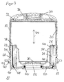
- FIG. 3 shows a sectional view of an air dryer cartridge according to the invention.
- the functioning of in FIG. 3 illustrated air dryer cartridge 10 according to the invention corresponds to FIG. 1
- a support member 18 which is coupled via snap connections 22, 24 with the spring cover 16.
- the snap connections 22, 24 form a frictional connection between the spring cover 16 and the support member 18, wherein the individual elements of the snap connections 22, 24 may be formed for example as hooks, knobs or beads on the spring cover 16 and / or the support member 18 and after Mounting in corresponding recesses or cutouts of the other part 18, 16 engage.
- the spring cover 16 and the support member 18 make it over the snap connections 22, 24 to be joined joining partners, which are pushed into one another during assembly of the air dryer cartridge 10 until the snap connections 22, 24 in an axial direction 74, or towards each other, where the hooks, knobs or beads used were passed past the associated recesses or recesses by elastic deformation of the joining partner and / or the hooks, nubs and beads themselves.
- Spring cover 16 and support member 18 are clipped together using the snap connections 22, 24.
- a projection 72 is arranged, which of a first seal 68 which seals between the support member 18 and the cartridge housing, not shown, and a second seal 70, which between the support member 18 and a not shown housing of the compressed air treatment plant (EAC) seals, is surrounded.
- This arrangement can be provided for example for mounting the air dryer cartridge 10 by means of a bayonet ring, not shown, on the compressed air treatment plant 12.
- Both seals 68, 70 thus represent seals that seal the interior of the compressed air supply system, which usually has an increased pressure level relative to the external environment during operation, against the environment.
- the spring cover 16 and the carrier element 18 can be formed, in particular, by cylindrical structures that are essentially open on one side, wherein the carrier element 18 provides the air inlet 50 and the air outlet 52.
- the carrier element 18 is similar in a manner not shown more like a circular ring over which the desiccant box 20 is pressed against the spring cover 16.
- the air inlet 50 and the air outlet 52 may be formed directly from the desiccant box 20.
- the carrier element 18 is manufactured in one piece with the desiccant box 20.
- the spring cover 16 would be "directly" coupled with the desiccant box 20, since a separate support member 18 would be omitted or would be regarded as part of the desiccant box 20.
- the diameter of the spring cover 16 perpendicular to the axial direction 74 may be larger or smaller than the diameter of the support member 18 or be selected to at least partially telescoping spring cover 16 and support member 18 until “snapping", that is until closing, the snap connections 22nd To allow 24. It is also conceivable that the diameter of the spring cover 16 corresponds to that of the carrier element 18, in which case the snap connections 22, 24 at the abutting edges of the cylinder walls engage each other during the joining in order to establish the connection.
- the overall height of the carrier element 18 in the axial direction 74 can be varied in a simple manner. in the The production of the air dryer cartridge 10 according to the invention will be briefly described below.
- the coalescing filter 26 is wound and fixed with the sleeve 28.
- the O-ring 44 is mounted on the bottom side of the desiccant box 20.
- the first air filter 30 is placed from above into the open desiccant box 20 and the desiccant box filled with a granular desiccant 38.
- the second air filter 32 is placed on top of the desiccant 38 and covered by the granule cover 36 upwards, so that the desiccant 38 can not trickle out of the desiccant box 20.
- the granule cover 36 is clamped by the compression spring 34 relative to the aufdin spring cover 16 and thereby pressed onto the desiccant 38. This avoids a mechanical breakdown of the granules by vibration and at the same time allows the automatic fixation of the desiccant 38 at a decreasing wear by level within the desiccant box 20 by lowering the granule cover 36. Subsequently, the support member 18 with the sealing ring 40, the first seal 68 and the second seal 70 equipped.
- the filled, preassembled container assembly consisting of the spring cover 16 and the filled desiccant box 20 is inserted into the carrier element 18 equipped with the seals 68, 70 and the sealing ring 40 and via the snap connections 22, 24 the desiccant box 20 between the spring cover 16 and clamped the carrier element 18.
- the sealing ring 40 is also conceivable to attach the sealing ring 40 to the desiccant box 20.
- Essential to the two possible arrangements is in each case the operability of the sealing lip 48 as a safety valve, which opens in the presence of an overpressure in the air dryer cartridge 10. In this way it is also possible to rinse out separated oil and dirt particles during a regeneration phase of the air dryer cartridge 10, bypassing the coalescing filter 26.
- the air dryer cartridge 10 can be stored or transported within the assembly without the entire assembly falling apart and without drying agent 38 trickles out.
- this module can also be placed in storage and used in case of service for easy replacement of the filter cartridge.
- the outer packaging essentially serves to protect the desiccant 38 from moisture.
- the assembly can be done by simply merging spring cover 16 and support member 18, with no additional steps or tools are required.
- the arrangement of the coalescing filter 26 in the air dryer cartridge 10 can be dispensed with.
Landscapes
- Engineering & Computer Science (AREA)
- Chemical & Material Sciences (AREA)
- Analytical Chemistry (AREA)
- General Chemical & Material Sciences (AREA)
- Oil, Petroleum & Natural Gas (AREA)
- Chemical Kinetics & Catalysis (AREA)
- Transportation (AREA)
- Mechanical Engineering (AREA)
- Drying Of Gases (AREA)
- Valves And Accessory Devices For Braking Systems (AREA)
- Compressor (AREA)
Description
- Die Erfindung betrifft eine Lufttrocknerpatrone für eine Druckluftaufbereitungsanlage eines Fahrzeugs, insbesondere eines Nutzfahrzeugs, mit einem Federdeckel und einem Trägerelement, die gemeinsam im zusammengebauten Zustand der Lufttrocknerpatrone ein Volumen der Lufttrocknerpatrone definieren wobei eine innerhalb des Volumens angeordnete, mit einem Trockenmittel gefüllte Trockenmittelbox vorgesehen ist, und wobei der Federdeckel und das Trägerelement als im Wesentlichen einseitig geschlossene Zylinder ausgeführt sind, an dessen offenen Enden Mittel beziehungsweise weitere Mittel zum Herstellen der Schnappverbindung angeordnet sind, über die der Federdeckel und das Trägerelement koppelbar sind.
- Die Erfindung betrifft weiterhin eine Druckluftaufbereitungsanlage für ein Fahrzeug, insbesondere ein Nutzfahrzeug, mit einer erfindungsgemäßen Lufttrocknerpatrone.
- Lufttrocknerpatronen werden als Verschleißteile im Rahmen der Druckluftbereitstellung beziehungsweise -aufbereitung für Druckluftaufbereitungsanlagen, kurz EAC, insbesondere im Nutzfahrzeugbereich benötigt. Dort werden sie zur Reinigung erzeugter Druckluft von Öl- und Schmutzpartikeln und zur Trocknung der Druckluft eingesetzt.
- Eine aus dem Stand der Technik bekannte Lufttrocknerpatrone ist in
Figur 1 dargestellt. Die gezeigte Lufttrocknerpatrone 10 besteht im Wesentlichen aus einer mit einem Trockenmittel 38 gefüllten Trockenmittelbox 20, die in einem Federdeckel 16 angeordnet ist. Der Federdeckel 16 wird im unteren Bereich von einer Bodenplatte 42 mit einem Lufteinlass 50 und einem Luftauslass 52 verschlossen. Die Bodenplatte 42 und der Federdeckel 16 sind über eine Bördelnaht 56 fest miteinander verbunden. Zwischen der Bodenplatte 42 und der Trockenmittelbox 20 dichten ein O-Ring 44 und ein Dichtring 40 mit einer Gummilippe 48, wobei die Gummilippe 48 als ein Rückschlagventil arbeitet. Der Dichtring 40 ist mechanisch oder chemisch mit der Trockenmittelbox 20 verbunden, wobei die Gummilippe 48 eine definierte Öffnungs- und Schließcharakteristik aufweist. Insbesondere öffnet die Gummilippe 48 bei einem Überdruck in der Lufttrocknerpatrone 10 und wirkt somit als Sicherheitsventil. Die Trockenmittelbox 20 ist in ihrer axialen Erstreckungsrichtung von einem ersten Luftfilter 30 und einem zweiten Luftfilter 32 begrenzt, welche das Trockenmittel 38 im Inneren der Trockenmittelbox 20 zurückhalten. Im oberen Bereich der Lufttrocknerpatrone 10 ist weiterhin eine Druckfeder 34 und ein Granulatdeckel 36 vorgesehen, über die das Trockenmittel 38 im Inneren der Trockenmittelbox 20 komprimiert wird. Der Granulatdeckel 36 ist insbesondere luftdurchlässig ausgeführt. Ein Kombinationsfilter, zum Beispiel in Form eines Koaleszenzfilters 26 erstreckt sich in axialer Richtung um die untere Hälfte der Trockenmittelbox 20 und wird in radialer Richtung von einer Manschette 28 an einer Tragekonstruktion 54 der Trockenmittelbox 20 fixiert. Das Koaleszenzfilter 26 unterteilt die Lufttrocknerpatrone 10 in einen Vorfilterbereich und einen Nachfilterbereich. Aufgabe des Koaleszenzfilters 26 während einer Druckluftförderphase ist es, Öl- und Schmutzpartikel sowie Emulsionströpfchen an einer Anströmfläche festzuhalten, flüssiges Öl zu speichern und feinste Öltröpfchen und Aerosole durch einen Koaleszenzeffekt in flüssiges Öl umzuwandeln und abzuscheiden. Die Auslegung von Ausströmfläche und Filteraufbau bewirkt dabei ein definiertes Verhältnis von Luftausströmgeschwindigkeit und Öltröpfchengröße. Dieses Verhältnis garantiert, dass keine Öltröpfchen über den Nachfilterbereich in die Trockenmittelbox 20 gelangen und so die Lebensdauer der Lufttrocknerpatrone 10 und nachgeordneter Verbraucher verkürzen. Luftleitelemente 46 ragen in radialer Richtung von der Trockenmittelbox 20 ausgehend in das Koaleszenzfilter 26 hinein und vermeiden eine Umgehung des Koaleszenzfilters durch einströmende Luft. Die Abdichtung während einer Druckluftförderphase zwischen Vorfilterbereich und Nachfilterbereich wird also durch eine spezielle Abdichtgeometrie, bestehend aus Luftleitelementen 46 in Verbindung mit der außenliegenden Manschette 28 erreicht. - Das Koaleszenzfilter 26 wird in azimutaler Richtung um die Trockenmittelbox 20, insbesondere auf die luftdurchlässige Tragekonstruktion 54, die Teil der Trockenmittelbox 20 ist, gewickelt. Dabei bildet das Filtermaterial des Koaleszenzfilters 26 zumindest eine Filterschicht in radialer Richtung. Die Manschette 28, die beispielsweise als eine elastische Gummimanschette ausgebildet sein kann, fixiert das Filtermaterial des Koaleszenzfilters 26 in radialer Richtung. Gleichzeitig erlaubt die Manschette 28 ein Atmen des Koaleszenzfilters 26 während der Ablagerung von Öl-und Schmutzpartikeln innerhalb des Filtermaterials und schützt das Koaleszenzfilter 26 vor Zerstörung. Das Filtermaterial des Koaleszenzfilters 26 grenzt direkt an die Trockenmittelbox 20.
- Weiterhin ist aus der
EP 0 230 991 A2 eine Lufttrocknerpatrone bekannt, bei der die Gehäuseteile der Lufttrocknerpatrone durch eine einen Sprengring umfassenden Schnappverbindung miteinander verbunden sind. - Aus der
US 4,838,901 A und derDE 198 27 566 A1 ist darüber hinaus jeweils ein Luftfilter bekannt, dessen Gehäuse mit zumindest einem flexiblen Paar aus "shoulders and posts" verschlossen ist beziehungsweise mithilfe einer Schnappverbindung zusammengefügt wurde. -
DE 199 55 898 A1 offenbart eine Trockenmittelbox zum Entfeuchten von Druckluftbremsanlagen. Die Trockenmittelbox umfasst ein Gehäuse mit einem Ein- und Auslass, wobei das Gehäuse von einem Behälter und einem Flansch gebildet ist. Weiterhin weist die Trockenmittelbox einen Trockenmittelkörper auf, der formstabil in das Gehäuse eingebracht ist. Durch die formstabile Ausführung des Trockenmittelkörpers können Bauteile, die zur Fixierung des granulatförmigen Trockenmittels erforderlich sind, eingespart werden. - Hiervon ausgehend liegt der vorliegenden Erfindung die Aufgabe zugrunde, den Aufbau einer Lufttrocknerpatrone zu vereinfachen.
- Diese Aufgabe wird mit den Merkmalen der unabhängigen Ansprüche gelöst.
- Vorteilhafte Ausführungsformen der Erfindung sind in den abhängigen Ansprüchen angegeben.
- Die Erfindung baut auf der gattungsgemäßen Lufttrocknerpatrone dadurch auf, dass die Mittel zum Herstellen der Schnappverbindung an dem Federdeckel von den weiteren Mitteln zum Herstellen der Schnappverbindung an dem Trägerelement senkrecht zu einer axialen Richtung beidseitig umfasst werden. Durch das beidseitige Umfassen erhält die Schnappverbindung eine ausreichende Dichtheit, so dass auf eine zusätzliche Dichtung zwischen dem Federdeckel und dem Trägerelement zur Abdichtung des Gehäuses der Lufttrocknerpatrone verzichtet werden kann. Zwischen dem Federdeckel und dem Trägerelement werden alle Teile der Lufttrocknerpatrone, insbesondere die notwendigen Teile, eingespannt. Die Teile der Lufttrocknerpatrone können, zum Beispiel einen Granulatdeckel, eine Druckfeder, eine Trockenmittelbox, Luftfilter in Form von Filtervlies, Trockenmittel, ein Rückschlagventil und einen kleinen O-Ring umfassen. Der kompakte Patroneneinsatz kann leicht als Einheit aus der Druckluftaufbereitungsanlage entnommen und ausgetauscht werden. Die lösbare Schnappverbindung erlaubt eine Wiederverwendung des Federdeckels, des Trägerelementes und weiterer Teile der Lufttrocknerpatrone, während verschlissene Bestandteile, insbesondere das Trockenmittel und Filtervliese, ausgetauscht werden können.
- Vorzugsweise kann vorgesehen sein, dass ein Koaleszenzfilter auf die Trockenmittelbox gewickelt und von einer Manschette fixiert ist. Das Aufwickeln des Koaleszenzfilters auf die Trockenmittelbox ermöglicht die Einsparung einer von der Trockenmittelbox separaten Trägervorrichtung, die das Koaleszenzfilter abseits der Trockenmittelbox innerhalb der Lufttrocknerpatrone positioniert.
- Besonders bevorzugt ist, dass an einem oberen und an einem unteren Ende der Trockenmittelbox Luftfilter angeordnet sind. Durch die Luftfilter kann das im Inneren der Trockenmittelbox vorhandene Trockenmittel am Verlassen der Trockenmittelbox gehindert werden.
- Es kann vorgesehen sein, dass ein durch eine Druckfeder gegenüber dem Federdeckel verspannter Granulatdeckel das Trockenmittel in der Trockenmittelbox fixiert. Auf diese Weise kann das üblicherweise als Granulat in der Trockenmittelbox vorliegende Trockenmittel in einer möglichst dichten Packung gehalten werden, wobei durch natürlichen Verschleiß auftretende Trockenmittelverluste durch eine Verkleinerung des zur Verfügung gestellten Volumens ausgeglichen werden können, um die dichte Packung zu erhalten.
- Weiterhin kann vorgesehen sein, dass das Trägerelement und die Trockenmittelbox einstückig gefertigt sind. Dies ermöglicht eine "direkte" Kopplung des Federdeckels mit der Trockenmittelbox ohne weitere Bauteile, so dass der Aufbau der Lufttrocknerpatrone insgesamt vereinfacht wird.
- Vorteilhafterweise kann vorgesehen sein, dass vor dem Befüllen der Trockenmittelbox mit Trockenmittel an einem unteren Ende der Trockenmittelbox ein erster Luftfilter angeordnet wird, und dass nach dem Befüllen der Trockenmittelbox mit Trockenmittel an einem oberen Ende der Trockenmittelbox ein zweiter Luftfilter angeordnet wird.
- Weiterhin kann vorgesehen sein, dass das Trockenmittel durch einen über eine Druckfeder gegenüber dem Federdeckel verspannten Granulatdeckel in der Trockenmittelbox fixiert wird.
- Es kann auch vorgesehen sein, dass das Trägerelement und die Trockenmittelbox einstückig gefertigt werden.
- Die Erfindung wird nun mit Bezug auf die begleitenden Zeichnungen anhand einer besonders bevorzugten Ausführungsform beispielhaft erläutert.
- Es zeigen:
- Figur 1
- eine Lufttrocknerpatrone gemäß dem Stand der Technik;
- Figur 2
- eine schematische Darstellung eines Fahrzeugs mit einer einen Lufttrockner mit Lufttrocknerpatrone umfassenden Durckluftaufbereitungsanlage; und
- Figur 3
- eine geschnittene Darstellung einer erfindungsgemäßen Lufttrocknerpatrone.
- In den folgenden Zeichnungen bezeichnen gleiche Bezugszeichen gleiche oder gleichartige Teile.
-
Figur 1 zeigt eine Lufttrocknerpatrone 10 gemäß dem Stand der Technik, deren Aufbau bereits beschrieben wurde. -
Figur 2 zeigt eine schematische Darstellung eines Fahrzeugs 14 mit einer einen Lufttrockner 58 mit Lufttrocknerpatrone 10 umfassenden Durckluftaufbereitungsanlage 12. Die Druckluftaufbereitungsanlage 12 erhält komprimierte Luft von einem Kompressor 64 und verteilt die aufbereitete Druckluft über Druckluftleitungen 66 an einzelne Verbraucher. Zu diesem Zweck ist eine verschiedene Ventile umfassende Ventileinrichtung 60 mit einer Entlüftung 62 vorgesehen, die von einem nicht dargstellten Steuergerät angesteuert werden kann. Die Ventileinrichtung 60 kann beispielsweise einen Druckregler und ein Mehrkreisschutzventil umfassen. Schematisch vereinfacht dargstellt sind inFigur 2 als Verbraucher Bremszylinder einer druckluftbetriebenen Bremsanlage ohne die notwendigen Ansteuerungsmöglichkeiten angedeutet. -
Figur 3 zeigt eine geschnittene Darstellung einer erfindungsgemäßen Lufttrocknerpatrone. Die Funktionsweise der inFigur 3 dargestellten erfindungsgemäßen Lufttrocknerpatrone 10 entspricht der ausFigur 1 bekannten Lufttrocknerpatrone 10. Anstelle der Bodenplatte 42, die über die Bördelnaht 56 mit dem Federdeckel 16 fest verbunden wird, tritt bei der dargestellten erfindungsgemäßen Ausführungsform ein Trägerelement 18, welches über Schnappverbindungen 22, 24 mit dem Federdeckel 16 gekoppelt wird. Die Schnappverbindungen 22, 24 bilden eine kraftformschlüssige Verbindung zwischen dem Federdeckel 16 und dem Trägerelement 18, wobei die einzelnen Elemente der Schnappverbindungen 22, 24 beispielsweise als Haken, Noppen oder Wülste an dem Federdeckel 16 und/oder dem Trägerelement 18 ausgebildet sein können und nach der Montage in entsprechende Vertiefungen oder Ausschnitte des jeweils anderen Teiles 18, 16 einrasten. Der Federdeckel 16 und das Trägerelement 18 stellen dabei über die Schnappverbindungen 22, 24 zu koppelnde Fügepartner dar, die während der Montage der Lufttrocknerpatrone 10 bis zum Einrasten der Schnappverbindungen 22, 24 in einer axialen Richtung 74 ineinander, beziehungsweise aufeinander zu, geschoben werden, wobei die verwendeten Haken, Noppen oder Wülste an den zugeordneten Vertiefungen beziehungsweise Ausnehmungen durch elastische Deformation der oder des Fügepartners und/oder den Haken, Noppen und Wülsten selbst vorbeigeführt wurden. - Federdeckel 16 und Trägerelement 18 werden dabei mit Hilfe der Schnappverbindungen 22, 24 zusammen geklippst. An dem Trägerelement 18 ist ein Vorsprung 72 angeordnet, der von einer ersten Abdichtung 68, die zwischen dem Trägerelement 18 und dem nicht dargestellten Patronengehäuse dichtet, und einer zweiten Abdichtung 70, die zwischen dem Trägerelement 18 und einem nicht dargestellten Gehäuse der Druckluftaufbereitungsanlage (EAC) dichtet, umgeben ist. Diese Anordnung kann beispielsweise zur Montage der Lufttrocknerpatrone 10 mit Hilfe eines nicht dargestellten Bajonettrings an der Druckluftaufbereitungsanlage 12 vorgesehen sein. Beide Abdichtungen 68, 70 stellen somit Dichtungen dar, die das Innere des Druckluftversorgungssystems, welches üblicherweise im Betrieb ein gegenüber der äußeren Umwelt erhöhtes Druckniveau aufweist, gegen die Umwelt abdichten. Der Federdeckel 16 und das Trägerelement 18 können insbesondere durch im Wesentlichen einseitig offene zylinderförmige Strukturen gebildet werden, wobei das Trägerelement 18 den Lufteinlass 50 und den Luftauslass 52 bereitstellt. Es ist jedoch auch denkbar, dass das Trägerelement 18 in nicht dargestellter Weise eher einem Kreisring gleicht, über den die Trockenmittelbox 20 gegen den Federdeckel 16 gepresst wird. In diesem Fall können der Lufteinlass 50 und der Luftauslass 52 direkt von der Trockenmittelbox 20 gebildet werden. Es ist ebenfalls möglich, dass das Trägerelement 18 einstückig mit der Trockenmittelbox 20 gefertigt ist. In diesem Fall würde der Federdeckel 16 "direkt" mit dem aus Trockenmittelbox 20 gekoppelt, da ein separates Trägerelement 18 entfallen würde beziehungsweise als Bestandteil der Trockenmittelbox 20 anzusehen wäre. Der Durchmesser des Federdeckels 16 senkrecht zur axialen Richtung 74 kann größer oder kleiner als der Durchmesser des Trägerelementes 18 beziehungsweise gewählt werden, um ein zumindest teilweises Ineinanderschieben von Federdeckel 16 und Trägerelement 18 bis zum "Einrasten", das heißt bis zum Schließen, der Schnappverbindungen 22, 24 zu ermöglichen. Es ist auch denkbar, dass der Durchmesser des Federdeckels 16 dem des Trägerelementes 18 entspricht, wobei dann beim Fügen die Schnappverbindungen 22, 24 an den aufeinander auftreffenden Rändern der Zylinderwände ineinander greifen, um die Verbindung herzustellen. Die Bauhöhe des Trägerelementes 18 in axialer Richtung 74 kann in einfacher Weise variiert werden. Im Folgenden wird die Herstellung der erfindungsgemäßen Lufttrocknerpatrone 10 kurz beschrieben.
- Auf die Trockenmittelbox 20 wird das Koaleszenzfilter 26 gewickelt und mit der Manschette 28 fixiert. Der O-Ring 44 wird auf der Bodenseite der Trockenmittelbox 20 montiert. Anschließend wird der erste Luftfilter 30 von oben in die offene Trockenmittelbox 20 gelegt und die Trockenmittelbox mit einem granularen Trockenmittel 38 gefüllt. Der zweite Luftfilter 32 wird von oben auf das Trockenmittel 38 gelegt und durch den Granulatdeckel 36 nach oben abgedeckt, damit das Trockenmittel 38 nicht aus der Trockenmittelbox 20 herausrieseln kann. Um Relativbewegungen innerhalb des Trockenmittels 38 zu verhindern, wird der Granulatdeckel 36 durch die Druckfeder 34 gegenüber dem aufzusetzenden Federdeckel 16 verspannt und dabei auf das Trockenmittel 38 gepresst. Dies vermeidet eine mechanische Zertrümmerung des Granulats durch Vibrationen und ermöglicht zugleich die automatische Fixierung des Trockenmittels 38 bei einem durch Verschleiß sinkenden Füllstand innerhalb der Trockenmittelbox 20 durch das Absenken des Granulatdeckels 36. Anschließend wird das Trägerelement 18 mit dem Dichtring 40, der ersten Abdichtung 68 und der zweiten Abdichtung 70 bestückt. Die gefüllte, vormontierte Behälterbaugruppe, bestehend aus dem Federdeckel 16 und der gefüllten Trockenmittelbox 20, wird in das mit den Abdichtungen 68, 70 und dem Dichtring 40 bestückte Trägerelement 18 eingesetzt und über die Schnappverbindungen 22, 24 wird die Trockenmittelbox 20 zwischen dem Federdeckel 16 und dem Trägerelement 18 eingespannt. Alternativ ist auch denkbar, den Dichtring 40 an der Trockenmittelbox 20 zu befestigen. Wesentlich bei den beiden Anordnungsmöglichkeiten ist jeweils die Funktionsfähigkeit der Dichtlippe 48 als Sicherheitsventil, die bei Vorliegen eines Überdruckes in der Lufttrocknerpatrone 10 öffnet. Auf diese Weise ist auch ein Ausspülen abgeschiedener Öl- und Schmutzpartikel während einer Regenerationsphase der Lufttrocknerpatrone 10 unter Umgehung des Koaleszenzfilters 26 möglich.
- Durch die Schnappverbindung 22, 24 kann die Lufttrocknerpatrone 10 innerhalb der Montage zwischengelagert oder transportiert werden, ohne dass die gesamte Baugruppe auseinander fällt und ohne dass Trockenmittel 38 herausrieselt. Durch eine entsprechende, nicht dargestellte Umverpackung kann diese Baugruppe auch auf Lager gelegt werden und im Servicefall zum leichten Austausch der Filterpatrone verwendet werden. Die Umverpackung dient dabei im Wesentlichen dem Schutz des Trockenmittels 38 vor Feuchtigkeit. Besonders vorteilhaft bei der erfindungsgemäßen Konstruktion ist, dass der Zusammenbau durch einfaches Zusammenführen von Federdeckel 16 und Trägerelement 18 erfolgen kann, wobei keine zusätzlichen Arbeitsschritte oder Werkzeuge erforderlich sind. Je nach Bedarf kann auf die Anordnung des Koaleszenzfilter 26 in der Lufttrocknerpatrone 10 verzichtet werden.
- Die in der vorstehenden Beschreibung, in den Zeichnungen sowie in den Ansprüchen offenbarten Merkmale der Erfindung können sowohl einzeln als auch in beliebiger Kombination für die Verwirklichung der Erfindung wesentlich sein.
-
- 10
- Lufttrocknerpatrone
- 12
- Druckluftaufbereitungsanlage
- 14
- Fahrzeug
- 16
- Federdeckel
- 18
- Trägerelement
- 20
- Trockenmittelbox
- 22
- Schnappverbindung
- 24
- Schnappverbindung
- 26
- Koaleszenzfilter
- 28
- Manschette
- 30
- erster Luftfilter
- 32
- zweiter Luftfilter
- 34
- Druckfeder
- 36
- Granulatdeckel
- 38
- Trockenmittel
- 40
- Dichtring
- 42
- Bodenplatte
- 44
- O-Ring
- 46
- Luftleitelement
- 48
- Gummilippe
- 50
- Lufteinlass
- 52
- Luftauslass
- 54
- Tragekonstruktion
- 56
- Bördelnaht
- 58
- Lufttrockner
- 60
- Ventileinrichtung
- 62
- Entlüftung
- 64
- Kompressor
- 66
- Druckluftleitung
- 68
- erste Abdichtung
- 70
- zweite Abdichtung
- 72
- Vorsprung
- 74
- axiale Richtung
Claims (6)
- Lufttrocknerpatrone (10) für eine Druckluftaufbereitungsanlage (12) eines Fahrzeugs (14), insbesondere eines Nutzfahrzeugs, mit- einem Federdeckel (16) und einem Trägerelement (18), die gemeinsam im zusammengebauten Zustand der Lufttrocknerpatrone (10) ein Volumen der Lufttrocknerpatrone (10) definieren,- wobei eine innerhalb des Volumens angeordnete, mit einem Trockenmittel (38) gefüllte Trockenmittelbox (20) vorgesehen ist, und- wobei der Federdeckel (16) und das Trägerelement (18) als im Wesentlichen einseitig geschlossene Zylinder ausgeführt sind, an dessen offenen Enden Mittel beziehungsweise weitere Mittel zum Herstellen der Schnappverbindung (22, 24) angeordnet sind, über die der Federdeckel (16) und das Trägerelement (18) koppelbar sind,dadurch gekennzeichnet, dass die Mittel zum Herstellen der Schnappverbindung (22, 24) an dem Federdeckel (16) von den weiteren Mitteln zum Herstellen der Schnappverbindung (22, 24) an dem Trägerelement (18) senkrecht zu einer axialen Richtung (74) beidseitig umfasst werden.
- Lufttrocknerpatrone (10) nach Anspruch 1, dadurch gekennzeichnet, dass ein Koaleszenzfilter (26) auf die Trockenmittelbox (20) gewickelt und von einer Manschette (28) fixiert ist.
- Lufttrocknerpatrone (10) nach Anspruch 1 oder 2, dadurch gekennzeichnet, dass an einem oberen und an einem unteren Ende der Trockenmittelbox (20) Luftfilter (30, 32) angeordnet sind.
- Lufttrocknerpatrone (10) nach einem der vorhergehenden Ansprüche, dadurch gekennzeichnet, dass ein durch eine Druckfeder (34) gegenüber dem Federdeckel (16) verspannter Granulatdeckel (36) das Trockenmittel in der Trockenmittelbox (20) fixiert.
- Lufttrocknerpatrone (10) nach einem der vorhergehenden Ansprüche, dadurch gekennzeichnet, dass das Trägerelement (18) und die Trockenmittelbox (20) einstückig gefertigt sind.
- Druckluftaufbereitungsanlage (12) für ein Fahrzeug (14), insbesondere ein Nutzfahrzeug, mit einer Lufttrocknerpatrone (10) nach einem der vorhergehenden Ansprüche.
Applications Claiming Priority (2)
| Application Number | Priority Date | Filing Date | Title |
|---|---|---|---|
| DE102009030897.0A DE102009030897B4 (de) | 2009-06-29 | 2009-06-29 | Lufttrocknerpatrone für eine Druckluftaufbereitungsanlage eines Fahrzeugs und Druckluftaufbereitungsanlage für ein Fahrzeug mit einer entsprechenden Lufttrocknerpatrone. |
| PCT/EP2010/058980 WO2011000766A1 (de) | 2009-06-29 | 2010-06-24 | Luftrocknerpatrone für eine druckluftaufbereitungsanlage eines fahrzeugs |
Publications (2)
| Publication Number | Publication Date |
|---|---|
| EP2448801A1 EP2448801A1 (de) | 2012-05-09 |
| EP2448801B1 true EP2448801B1 (de) | 2014-08-13 |
Family
ID=42670652
Family Applications (1)
| Application Number | Title | Priority Date | Filing Date |
|---|---|---|---|
| EP10726968.0A Active EP2448801B1 (de) | 2009-06-29 | 2010-06-24 | Lufttrocknerpatrone für eine druckluftaufbereitungsanlage eines fahrzeugs |
Country Status (8)
| Country | Link |
|---|---|
| US (1) | US8657939B2 (de) |
| EP (1) | EP2448801B1 (de) |
| CN (1) | CN102448783B (de) |
| CA (1) | CA2766519C (de) |
| DE (1) | DE102009030897B4 (de) |
| MX (1) | MX2011013826A (de) |
| RU (1) | RU2532035C2 (de) |
| WO (1) | WO2011000766A1 (de) |
Cited By (1)
| Publication number | Priority date | Publication date | Assignee | Title |
|---|---|---|---|---|
| DE102016002385A1 (de) | 2016-03-01 | 2017-09-07 | Knorr-Bremse Systeme für Nutzfahrzeuge GmbH | Lufttrocknerpatrone und Schraubenfeder für Lufttrocknerpatrone |
Families Citing this family (22)
| Publication number | Priority date | Publication date | Assignee | Title |
|---|---|---|---|---|
| TR201107171A2 (tr) * | 2011-07-20 | 2012-12-21 | Asaş Fi̇ltre Sanayi̇ Ve Ti̇caret Anoni̇m Şi̇rketi̇ | Bir hava kurutucu filtre. |
| US8852327B1 (en) * | 2013-03-14 | 2014-10-07 | Haldex Brake Products Corporation | Air dryer cartridge with integrated check valve |
| DE102013103066A1 (de) | 2013-03-26 | 2014-10-02 | Knorr-Bremse Systeme für Nutzfahrzeuge GmbH | Luftfilterpatrone mit integriertem Koaleszenzfilter/Grobschmutzfilter und Trockenmittelfüllung |
| EP3018021B1 (de) | 2014-10-28 | 2019-12-04 | Parker-Hannificn Corporation | Kombinierter öl- und wasserabscheider in einem luftbremsentrockner |
| DE102015112488A1 (de) | 2015-07-30 | 2017-02-02 | Knorr-Bremse Systeme für Nutzfahrzeuge GmbH | Lufttrocknerpatrone |
| CN105032134A (zh) * | 2015-07-30 | 2015-11-11 | 瑞立集团瑞安汽车零部件有限公司 | 一种滤油干燥筒及采用该干燥筒的空气干燥器 |
| DE102015013493A1 (de) * | 2015-10-16 | 2017-04-20 | Man Truck & Bus Ag | Vorrichtung zur lösbaren Befestigung einer Trockenmittelpatrone an einem Gehäuse einer Druckluftaufbereitungsanlage eines Fahrzeugs |
| DE102015122169A1 (de) * | 2015-12-18 | 2017-06-22 | Knorr-Bremse Systeme für Nutzfahrzeuge GmbH | Lufttrocknerpatrone |
| DE102015122168A1 (de) * | 2015-12-18 | 2017-06-22 | Knorr-Bremse Systeme für Nutzfahrzeuge GmbH | Lufttrocknerpatrone |
| CA3020723C (en) * | 2016-04-11 | 2024-02-20 | Carleton Life Support Systems, Inc. | Sieve bed retention system |
| DE102016208355A1 (de) * | 2016-05-13 | 2017-11-16 | Knorr-Bremse Systeme für Nutzfahrzeuge GmbH | Druckluftaufbereitungssystem, insbesondere für eine Druckluftaufbereitungsanlage eines Nutzfahrzeugs |
| DE102016120477A1 (de) * | 2016-10-27 | 2018-05-03 | Knorr-Bremse Systeme für Nutzfahrzeuge GmbH | Lufttrocknerpatrone |
| WO2018104152A1 (en) * | 2016-12-05 | 2018-06-14 | Volvo Truck Corporation | An air processing assembly comprising a ptfe based oleophobic membrane and method for drying compressed air for a vehicle |
| CN108328679A (zh) * | 2018-03-28 | 2018-07-27 | 佛山市顺德区美的饮水机制造有限公司 | 滤芯组件及净水器 |
| DE102019200188A1 (de) * | 2019-01-09 | 2020-07-09 | Knorr-Bremse Systeme für Nutzfahrzeuge GmbH | Verfahren zum Verbinden eines Filtermaterials mit einem fluidtechnischen Bauteil und System aus einem fluidtechnischen Bauteil und einem damit verbindbaren Filtermaterial |
| DE102019122452A1 (de) * | 2019-08-21 | 2021-02-25 | Knorr-Bremse Systeme für Nutzfahrzeuge GmbH | Rückschlagventil-Vorrichtung |
| EP4265319A1 (de) * | 2020-12-18 | 2023-10-25 | Semyungtech Co., Ltd. | Lufttrocknerpatrone |
| WO2022152531A1 (en) | 2021-01-12 | 2022-07-21 | Knorr-Bremse Systeme für Nutzfahrzeuge GmbH | Fixing interface, air dryer cartridge and air treatment device |
| EP4026605A1 (de) | 2021-01-12 | 2022-07-13 | KNORR-BREMSE Systeme für Nutzfahrzeuge GmbH | Befestigungsschnittstelle, lufttrocknerkartusche und luftbehandlungsvorrichtung |
| EP4026604A1 (de) | 2021-01-12 | 2022-07-13 | KNORR-BREMSE Systeme für Nutzfahrzeuge GmbH | Lufttrocknerkartusche mit dichtungsschnittstelle und luftbehandlungsvorrichtung |
| EP4296128B1 (de) | 2022-06-21 | 2025-06-11 | KNORR-BREMSE Systeme für Nutzfahrzeuge GmbH | Positionier- und montageschnittstelle, trockenmittelpatrone und luftsteuervorrichtung |
| EP4420944A1 (de) | 2023-02-24 | 2024-08-28 | KNORR-BREMSE Systeme für Nutzfahrzeuge GmbH | Filteranordnung für ein druckluftaufbereitungssystem eines fahrzeugs |
Family Cites Families (11)
| Publication number | Priority date | Publication date | Assignee | Title |
|---|---|---|---|---|
| SU1088766A1 (ru) * | 1983-02-07 | 1984-04-30 | Опытное Конструкторско-Технологическое Бюро "Кристалл" С Опытным Производством Ленинградского Технологического Института Им.Ленсовета | Устройство дл осушки газов |
| DE3603043A1 (de) * | 1986-01-31 | 1987-08-06 | Knorr Bremse Ag | Trocknungspatrone fuer lufttrocknungsanlagen, insbesondere fuer druckluftbremsanlagen von fahrzeugen |
| US4838901A (en) * | 1988-05-17 | 1989-06-13 | Life Systems, Inc. | Lightweight filter |
| DE19510193A1 (de) | 1995-03-21 | 1996-09-26 | Voss Armaturen | Anschlußvorrichtung für Rohrleitungen |
| DE19827566B4 (de) * | 1997-07-01 | 2007-07-12 | Mahle Filtersysteme Gmbh | Lufttrocknerpatrone |
| DE19955898A1 (de) * | 1999-11-20 | 2001-05-23 | Mann & Hummel Filter | Trockenmittelbox |
| GB0311471D0 (en) * | 2003-05-19 | 2003-06-25 | Wabco Automotive Uk Ltd | Air dryer cartridge |
| FR2857275B1 (fr) * | 2003-07-07 | 2006-12-01 | Henkel France | Dispositif d'absorption d'humidite |
| DE102005033083B3 (de) * | 2005-07-15 | 2006-12-28 | Knorr-Bremse Systeme für Nutzfahrzeuge GmbH | Verfahren zur Luftaufbereitung und Luftaufbereitungsanlage |
| US7908730B2 (en) * | 2006-07-11 | 2011-03-22 | Haldex Brake Corporation | PTC fitting cartridge |
| DE102008031326B4 (de) * | 2008-07-02 | 2010-04-08 | Knorr-Bremse Systeme für Nutzfahrzeuge GmbH | Druckluftversorgungseinrichtung |
-
2009
- 2009-06-29 DE DE102009030897.0A patent/DE102009030897B4/de not_active Expired - Fee Related
-
2010
- 2010-06-24 WO PCT/EP2010/058980 patent/WO2011000766A1/de not_active Ceased
- 2010-06-24 EP EP10726968.0A patent/EP2448801B1/de active Active
- 2010-06-24 RU RU2012102995/11A patent/RU2532035C2/ru active
- 2010-06-24 MX MX2011013826A patent/MX2011013826A/es active IP Right Grant
- 2010-06-24 CA CA2766519A patent/CA2766519C/en not_active Expired - Fee Related
- 2010-06-24 CN CN201080024076.8A patent/CN102448783B/zh active Active
-
2011
- 2011-12-22 US US13/334,937 patent/US8657939B2/en active Active
Cited By (3)
| Publication number | Priority date | Publication date | Assignee | Title |
|---|---|---|---|---|
| DE102016002385A1 (de) | 2016-03-01 | 2017-09-07 | Knorr-Bremse Systeme für Nutzfahrzeuge GmbH | Lufttrocknerpatrone und Schraubenfeder für Lufttrocknerpatrone |
| WO2017148778A1 (de) | 2016-03-01 | 2017-09-08 | Knorr-Bremse Systeme für Nutzfahrzeuge GmbH | Lufttrocknerpatrone und schraubenfeder für lufttrocknerpatrone |
| US11007992B2 (en) | 2016-03-01 | 2021-05-18 | Knorr-Bremse Systeme Fuer Nutzfahrzeuge Gmbh | Air-dryer cartridge and helical spring for an air-dryer cartridge |
Also Published As
| Publication number | Publication date |
|---|---|
| EP2448801A1 (de) | 2012-05-09 |
| CN102448783B (zh) | 2015-01-21 |
| WO2011000766A1 (de) | 2011-01-06 |
| CA2766519A1 (en) | 2011-01-06 |
| DE102009030897A1 (de) | 2011-01-05 |
| MX2011013826A (es) | 2012-01-30 |
| US8657939B2 (en) | 2014-02-25 |
| US20120118157A1 (en) | 2012-05-17 |
| RU2012102995A (ru) | 2013-08-10 |
| CN102448783A (zh) | 2012-05-09 |
| RU2532035C2 (ru) | 2014-10-27 |
| CA2766519C (en) | 2017-05-09 |
| DE102009030897B4 (de) | 2015-02-26 |
Similar Documents
| Publication | Publication Date | Title |
|---|---|---|
| EP2448801B1 (de) | Lufttrocknerpatrone für eine druckluftaufbereitungsanlage eines fahrzeugs | |
| EP2768598B1 (de) | Luftfilterpatrone zur druckluftaufbereitung für eine druckluftaufbereitungsanlage | |
| EP2192970B1 (de) | Trockenmittelpatrone für eine druckluftaufbereitungsanlage und verfahren zur herstellung einer trockenmittelpatrone | |
| EP2861323B1 (de) | Lufttrocknerpatrone und verfahren zur herstellung einer lufttrocknerpatrone | |
| DE102007011256B4 (de) | Druckluftversorgungseinrichtung mit verbesserter Regenerationsfähigkeit | |
| EP2051891A1 (de) | Druckluftversorgungseinrichtung | |
| EP2978646B1 (de) | Lufttrocknerpatrone mit integriertem koaleszenzfilter/grobschmutzfilter | |
| DE102014006853A1 (de) | Hohlfilterelement, Filtergehäuse und Filter | |
| DE8224847U1 (de) | Trocknungsvorrichtung fuer lufttrockner | |
| DE102008031326B4 (de) | Druckluftversorgungseinrichtung | |
| EP2051892A1 (de) | Druckluftversorgungseinrichtung für ein nutzfahrzeug und lufttrocknerpatrone | |
| DE102007034435A1 (de) | Trockenmittelbox zum Entfeuchten von Luft | |
| DE102016002385A1 (de) | Lufttrocknerpatrone und Schraubenfeder für Lufttrocknerpatrone | |
| EP2881156A1 (de) | Filterelement mit einem Bypasskanal sowie Filteranordnung mit einem Filterelement | |
| EP2176097B1 (de) | Filterelement und filteranordnung | |
| EP3328700B1 (de) | Lufttrocknerpatrone | |
| EP4017770B1 (de) | Rückschlagventil-vorrichtung | |
| EP3359282B1 (de) | Trockenmittelpatrone mit verbesserter trocknung und regeneration | |
| EP3418143B1 (de) | Vorrichtung zur lösbaren befestigung einer trockenmittelpatrone an einem gehäuse einer druckluftaufbereitungsanlage eines fahrzeugs | |
| EP2452739A1 (de) | Innenraumluftfilter und Filteranordnung | |
| DE102009004021B3 (de) | Druckluftversorgungseinrichtung, Ventilgehäuse und Lufttrocknerpatrone | |
| EP3532187A1 (de) | Lufttrocknerpatrone | |
| EP4426468A1 (de) | Rundfilterelement zur filtration eines gasförmigen fluids |
Legal Events
| Date | Code | Title | Description |
|---|---|---|---|
| PUAI | Public reference made under article 153(3) epc to a published international application that has entered the european phase |
Free format text: ORIGINAL CODE: 0009012 |
|
| 17P | Request for examination filed |
Effective date: 20120130 |
|
| AK | Designated contracting states |
Kind code of ref document: A1 Designated state(s): AL AT BE BG CH CY CZ DE DK EE ES FI FR GB GR HR HU IE IS IT LI LT LU LV MC MK MT NL NO PL PT RO SE SI SK SM TR |
|
| DAX | Request for extension of the european patent (deleted) | ||
| GRAP | Despatch of communication of intention to grant a patent |
Free format text: ORIGINAL CODE: EPIDOSNIGR1 |
|
| INTG | Intention to grant announced |
Effective date: 20140131 |
|
| GRAS | Grant fee paid |
Free format text: ORIGINAL CODE: EPIDOSNIGR3 |
|
| GRAA | (expected) grant |
Free format text: ORIGINAL CODE: 0009210 |
|
| AK | Designated contracting states |
Kind code of ref document: B1 Designated state(s): AL AT BE BG CH CY CZ DE DK EE ES FI FR GB GR HR HU IE IS IT LI LT LU LV MC MK MT NL NO PL PT RO SE SI SK SM TR |
|
| REG | Reference to a national code |
Ref country code: GB Ref legal event code: FG4D Free format text: NOT ENGLISH |
|
| REG | Reference to a national code |
Ref country code: CH Ref legal event code: EP Ref country code: AT Ref legal event code: REF Ref document number: 682018 Country of ref document: AT Kind code of ref document: T Effective date: 20140815 |
|
| REG | Reference to a national code |
Ref country code: IE Ref legal event code: FG4D Free format text: LANGUAGE OF EP DOCUMENT: GERMAN |
|
| REG | Reference to a national code |
Ref country code: DE Ref legal event code: R096 Ref document number: 502010007667 Country of ref document: DE Effective date: 20140925 |
|
| REG | Reference to a national code |
Ref country code: SE Ref legal event code: TRGR |
|
| REG | Reference to a national code |
Ref country code: NL Ref legal event code: T3 |
|
| REG | Reference to a national code |
Ref country code: LT Ref legal event code: MG4D |
|
| PG25 | Lapsed in a contracting state [announced via postgrant information from national office to epo] |
Ref country code: NO Free format text: LAPSE BECAUSE OF FAILURE TO SUBMIT A TRANSLATION OF THE DESCRIPTION OR TO PAY THE FEE WITHIN THE PRESCRIBED TIME-LIMIT Effective date: 20141113 Ref country code: PT Free format text: LAPSE BECAUSE OF FAILURE TO SUBMIT A TRANSLATION OF THE DESCRIPTION OR TO PAY THE FEE WITHIN THE PRESCRIBED TIME-LIMIT Effective date: 20141215 Ref country code: FI Free format text: LAPSE BECAUSE OF FAILURE TO SUBMIT A TRANSLATION OF THE DESCRIPTION OR TO PAY THE FEE WITHIN THE PRESCRIBED TIME-LIMIT Effective date: 20140813 Ref country code: LT Free format text: LAPSE BECAUSE OF FAILURE TO SUBMIT A TRANSLATION OF THE DESCRIPTION OR TO PAY THE FEE WITHIN THE PRESCRIBED TIME-LIMIT Effective date: 20140813 Ref country code: ES Free format text: LAPSE BECAUSE OF FAILURE TO SUBMIT A TRANSLATION OF THE DESCRIPTION OR TO PAY THE FEE WITHIN THE PRESCRIBED TIME-LIMIT Effective date: 20140813 Ref country code: GR Free format text: LAPSE BECAUSE OF FAILURE TO SUBMIT A TRANSLATION OF THE DESCRIPTION OR TO PAY THE FEE WITHIN THE PRESCRIBED TIME-LIMIT Effective date: 20141114 Ref country code: BG Free format text: LAPSE BECAUSE OF FAILURE TO SUBMIT A TRANSLATION OF THE DESCRIPTION OR TO PAY THE FEE WITHIN THE PRESCRIBED TIME-LIMIT Effective date: 20141113 |
|
| PG25 | Lapsed in a contracting state [announced via postgrant information from national office to epo] |
Ref country code: LV Free format text: LAPSE BECAUSE OF FAILURE TO SUBMIT A TRANSLATION OF THE DESCRIPTION OR TO PAY THE FEE WITHIN THE PRESCRIBED TIME-LIMIT Effective date: 20140813 Ref country code: HR Free format text: LAPSE BECAUSE OF FAILURE TO SUBMIT A TRANSLATION OF THE DESCRIPTION OR TO PAY THE FEE WITHIN THE PRESCRIBED TIME-LIMIT Effective date: 20140813 Ref country code: CY Free format text: LAPSE BECAUSE OF FAILURE TO SUBMIT A TRANSLATION OF THE DESCRIPTION OR TO PAY THE FEE WITHIN THE PRESCRIBED TIME-LIMIT Effective date: 20140813 Ref country code: IS Free format text: LAPSE BECAUSE OF FAILURE TO SUBMIT A TRANSLATION OF THE DESCRIPTION OR TO PAY THE FEE WITHIN THE PRESCRIBED TIME-LIMIT Effective date: 20141213 |
|
| PG25 | Lapsed in a contracting state [announced via postgrant information from national office to epo] |
Ref country code: SK Free format text: LAPSE BECAUSE OF FAILURE TO SUBMIT A TRANSLATION OF THE DESCRIPTION OR TO PAY THE FEE WITHIN THE PRESCRIBED TIME-LIMIT Effective date: 20140813 Ref country code: CZ Free format text: LAPSE BECAUSE OF FAILURE TO SUBMIT A TRANSLATION OF THE DESCRIPTION OR TO PAY THE FEE WITHIN THE PRESCRIBED TIME-LIMIT Effective date: 20140813 Ref country code: EE Free format text: LAPSE BECAUSE OF FAILURE TO SUBMIT A TRANSLATION OF THE DESCRIPTION OR TO PAY THE FEE WITHIN THE PRESCRIBED TIME-LIMIT Effective date: 20140813 Ref country code: RO Free format text: LAPSE BECAUSE OF FAILURE TO SUBMIT A TRANSLATION OF THE DESCRIPTION OR TO PAY THE FEE WITHIN THE PRESCRIBED TIME-LIMIT Effective date: 20140813 Ref country code: DK Free format text: LAPSE BECAUSE OF FAILURE TO SUBMIT A TRANSLATION OF THE DESCRIPTION OR TO PAY THE FEE WITHIN THE PRESCRIBED TIME-LIMIT Effective date: 20140813 |
|
| REG | Reference to a national code |
Ref country code: DE Ref legal event code: R097 Ref document number: 502010007667 Country of ref document: DE |
|
| PG25 | Lapsed in a contracting state [announced via postgrant information from national office to epo] |
Ref country code: PL Free format text: LAPSE BECAUSE OF FAILURE TO SUBMIT A TRANSLATION OF THE DESCRIPTION OR TO PAY THE FEE WITHIN THE PRESCRIBED TIME-LIMIT Effective date: 20140813 |
|
| PLBE | No opposition filed within time limit |
Free format text: ORIGINAL CODE: 0009261 |
|
| STAA | Information on the status of an ep patent application or granted ep patent |
Free format text: STATUS: NO OPPOSITION FILED WITHIN TIME LIMIT |
|
| 26N | No opposition filed |
Effective date: 20150515 |
|
| PG25 | Lapsed in a contracting state [announced via postgrant information from national office to epo] |
Ref country code: SI Free format text: LAPSE BECAUSE OF FAILURE TO SUBMIT A TRANSLATION OF THE DESCRIPTION OR TO PAY THE FEE WITHIN THE PRESCRIBED TIME-LIMIT Effective date: 20140813 |
|
| PG25 | Lapsed in a contracting state [announced via postgrant information from national office to epo] |
Ref country code: MC Free format text: LAPSE BECAUSE OF FAILURE TO SUBMIT A TRANSLATION OF THE DESCRIPTION OR TO PAY THE FEE WITHIN THE PRESCRIBED TIME-LIMIT Effective date: 20140813 |
|
| REG | Reference to a national code |
Ref country code: CH Ref legal event code: PL |
|
| PG25 | Lapsed in a contracting state [announced via postgrant information from national office to epo] |
Ref country code: LU Free format text: LAPSE BECAUSE OF FAILURE TO SUBMIT A TRANSLATION OF THE DESCRIPTION OR TO PAY THE FEE WITHIN THE PRESCRIBED TIME-LIMIT Effective date: 20150624 |
|
| REG | Reference to a national code |
Ref country code: IE Ref legal event code: MM4A |
|
| PG25 | Lapsed in a contracting state [announced via postgrant information from national office to epo] |
Ref country code: LI Free format text: LAPSE BECAUSE OF NON-PAYMENT OF DUE FEES Effective date: 20150630 Ref country code: CH Free format text: LAPSE BECAUSE OF NON-PAYMENT OF DUE FEES Effective date: 20150630 Ref country code: IE Free format text: LAPSE BECAUSE OF NON-PAYMENT OF DUE FEES Effective date: 20150624 |
|
| REG | Reference to a national code |
Ref country code: FR Ref legal event code: PLFP Year of fee payment: 7 |
|
| REG | Reference to a national code |
Ref country code: AT Ref legal event code: MM01 Ref document number: 682018 Country of ref document: AT Kind code of ref document: T Effective date: 20150624 |
|
| PG25 | Lapsed in a contracting state [announced via postgrant information from national office to epo] |
Ref country code: AT Free format text: LAPSE BECAUSE OF NON-PAYMENT OF DUE FEES Effective date: 20150624 |
|
| PG25 | Lapsed in a contracting state [announced via postgrant information from national office to epo] |
Ref country code: MT Free format text: LAPSE BECAUSE OF FAILURE TO SUBMIT A TRANSLATION OF THE DESCRIPTION OR TO PAY THE FEE WITHIN THE PRESCRIBED TIME-LIMIT Effective date: 20140813 |
|
| PG25 | Lapsed in a contracting state [announced via postgrant information from national office to epo] |
Ref country code: SM Free format text: LAPSE BECAUSE OF FAILURE TO SUBMIT A TRANSLATION OF THE DESCRIPTION OR TO PAY THE FEE WITHIN THE PRESCRIBED TIME-LIMIT Effective date: 20140813 Ref country code: HU Free format text: LAPSE BECAUSE OF FAILURE TO SUBMIT A TRANSLATION OF THE DESCRIPTION OR TO PAY THE FEE WITHIN THE PRESCRIBED TIME-LIMIT; INVALID AB INITIO Effective date: 20100624 |
|
| REG | Reference to a national code |
Ref country code: FR Ref legal event code: PLFP Year of fee payment: 8 |
|
| PG25 | Lapsed in a contracting state [announced via postgrant information from national office to epo] |
Ref country code: BE Free format text: LAPSE BECAUSE OF NON-PAYMENT OF DUE FEES Effective date: 20150630 |
|
| REG | Reference to a national code |
Ref country code: FR Ref legal event code: PLFP Year of fee payment: 9 |
|
| PG25 | Lapsed in a contracting state [announced via postgrant information from national office to epo] |
Ref country code: MK Free format text: LAPSE BECAUSE OF FAILURE TO SUBMIT A TRANSLATION OF THE DESCRIPTION OR TO PAY THE FEE WITHIN THE PRESCRIBED TIME-LIMIT Effective date: 20140813 |
|
| PG25 | Lapsed in a contracting state [announced via postgrant information from national office to epo] |
Ref country code: AL Free format text: LAPSE BECAUSE OF FAILURE TO SUBMIT A TRANSLATION OF THE DESCRIPTION OR TO PAY THE FEE WITHIN THE PRESCRIBED TIME-LIMIT Effective date: 20140813 |
|
| P01 | Opt-out of the competence of the unified patent court (upc) registered |
Effective date: 20230607 |
|
| PGFP | Annual fee paid to national office [announced via postgrant information from national office to epo] |
Ref country code: DE Payment date: 20250626 Year of fee payment: 16 |
|
| PGFP | Annual fee paid to national office [announced via postgrant information from national office to epo] |
Ref country code: GB Payment date: 20250617 Year of fee payment: 16 |
|
| PGFP | Annual fee paid to national office [announced via postgrant information from national office to epo] |
Ref country code: NL Payment date: 20250624 Year of fee payment: 16 |
|
| PGFP | Annual fee paid to national office [announced via postgrant information from national office to epo] |
Ref country code: FR Payment date: 20250624 Year of fee payment: 16 |
|
| PGFP | Annual fee paid to national office [announced via postgrant information from national office to epo] |
Ref country code: TR Payment date: 20250604 Year of fee payment: 16 |
|
| PGFP | Annual fee paid to national office [announced via postgrant information from national office to epo] |
Ref country code: SE Payment date: 20250619 Year of fee payment: 16 |
|
| PGFP | Annual fee paid to national office [announced via postgrant information from national office to epo] |
Ref country code: IT Payment date: 20250623 Year of fee payment: 16 |