EP3018021B1 - Kombinierter öl- und wasserabscheider in einem luftbremsentrockner - Google Patents
Kombinierter öl- und wasserabscheider in einem luftbremsentrockner Download PDFInfo
- Publication number
- EP3018021B1 EP3018021B1 EP15191744.0A EP15191744A EP3018021B1 EP 3018021 B1 EP3018021 B1 EP 3018021B1 EP 15191744 A EP15191744 A EP 15191744A EP 3018021 B1 EP3018021 B1 EP 3018021B1
- Authority
- EP
- European Patent Office
- Prior art keywords
- filter element
- filter
- coalescing media
- fluid
- shroud
- Prior art date
- Legal status (The legal status is an assumption and is not a legal conclusion. Google has not performed a legal analysis and makes no representation as to the accuracy of the status listed.)
- Active
Links
- XLYOFNOQVPJJNP-UHFFFAOYSA-N water Substances O XLYOFNOQVPJJNP-UHFFFAOYSA-N 0.000 title description 14
- 239000012530 fluid Substances 0.000 claims description 80
- 238000010926 purge Methods 0.000 claims description 68
- 239000002274 desiccant Substances 0.000 claims description 40
- 239000007788 liquid Substances 0.000 claims description 35
- 230000000994 depressogenic effect Effects 0.000 claims description 6
- 239000003921 oil Substances 0.000 description 19
- 230000007246 mechanism Effects 0.000 description 4
- 229910000831 Steel Inorganic materials 0.000 description 2
- 239000003570 air Substances 0.000 description 2
- 239000000356 contaminant Substances 0.000 description 2
- 238000001035 drying Methods 0.000 description 2
- 238000000926 separation method Methods 0.000 description 2
- 239000010959 steel Substances 0.000 description 2
- 238000004140 cleaning Methods 0.000 description 1
- 239000010687 lubricating oil Substances 0.000 description 1
- 238000005461 lubrication Methods 0.000 description 1
- 239000000463 material Substances 0.000 description 1
- 239000002184 metal Substances 0.000 description 1
- 239000000203 mixture Substances 0.000 description 1
- 239000002245 particle Substances 0.000 description 1
Images


Classifications
-
- B—PERFORMING OPERATIONS; TRANSPORTING
- B60—VEHICLES IN GENERAL
- B60T—VEHICLE BRAKE CONTROL SYSTEMS OR PARTS THEREOF; BRAKE CONTROL SYSTEMS OR PARTS THEREOF, IN GENERAL; ARRANGEMENT OF BRAKING ELEMENTS ON VEHICLES IN GENERAL; PORTABLE DEVICES FOR PREVENTING UNWANTED MOVEMENT OF VEHICLES; VEHICLE MODIFICATIONS TO FACILITATE COOLING OF BRAKES
- B60T17/00—Component parts, details, or accessories of power brake systems not covered by groups B60T8/00, B60T13/00 or B60T15/00, or presenting other characteristic features
- B60T17/002—Air treatment devices
- B60T17/004—Draining and drying devices
-
- B—PERFORMING OPERATIONS; TRANSPORTING
- B01—PHYSICAL OR CHEMICAL PROCESSES OR APPARATUS IN GENERAL
- B01D—SEPARATION
- B01D46/00—Filters or filtering processes specially modified for separating dispersed particles from gases or vapours
- B01D46/0027—Filters or filtering processes specially modified for separating dispersed particles from gases or vapours with additional separating or treating functions
- B01D46/003—Filters or filtering processes specially modified for separating dispersed particles from gases or vapours with additional separating or treating functions including coalescing means for the separation of liquid
- B01D46/0031—Filters or filtering processes specially modified for separating dispersed particles from gases or vapours with additional separating or treating functions including coalescing means for the separation of liquid with collecting, draining means
-
- B—PERFORMING OPERATIONS; TRANSPORTING
- B01—PHYSICAL OR CHEMICAL PROCESSES OR APPARATUS IN GENERAL
- B01D—SEPARATION
- B01D46/00—Filters or filtering processes specially modified for separating dispersed particles from gases or vapours
- B01D46/0027—Filters or filtering processes specially modified for separating dispersed particles from gases or vapours with additional separating or treating functions
- B01D46/0036—Filters or filtering processes specially modified for separating dispersed particles from gases or vapours with additional separating or treating functions by adsorption or absorption
-
- B—PERFORMING OPERATIONS; TRANSPORTING
- B01—PHYSICAL OR CHEMICAL PROCESSES OR APPARATUS IN GENERAL
- B01D—SEPARATION
- B01D46/00—Filters or filtering processes specially modified for separating dispersed particles from gases or vapours
- B01D46/0039—Filters or filtering processes specially modified for separating dispersed particles from gases or vapours with flow guiding by feed or discharge devices
- B01D46/0041—Filters or filtering processes specially modified for separating dispersed particles from gases or vapours with flow guiding by feed or discharge devices for feeding
- B01D46/0045—Filters or filtering processes specially modified for separating dispersed particles from gases or vapours with flow guiding by feed or discharge devices for feeding by using vanes
-
- B—PERFORMING OPERATIONS; TRANSPORTING
- B01—PHYSICAL OR CHEMICAL PROCESSES OR APPARATUS IN GENERAL
- B01D—SEPARATION
- B01D46/00—Filters or filtering processes specially modified for separating dispersed particles from gases or vapours
- B01D46/24—Particle separators, e.g. dust precipitators, using rigid hollow filter bodies
- B01D46/2403—Particle separators, e.g. dust precipitators, using rigid hollow filter bodies characterised by the physical shape or structure of the filtering element
- B01D46/2411—Filter cartridges
- B01D46/2414—End caps including additional functions or special forms
-
- B—PERFORMING OPERATIONS; TRANSPORTING
- B01—PHYSICAL OR CHEMICAL PROCESSES OR APPARATUS IN GENERAL
- B01D—SEPARATION
- B01D53/00—Separation of gases or vapours; Recovering vapours of volatile solvents from gases; Chemical or biological purification of waste gases, e.g. engine exhaust gases, smoke, fumes, flue gases, aerosols
- B01D53/02—Separation of gases or vapours; Recovering vapours of volatile solvents from gases; Chemical or biological purification of waste gases, e.g. engine exhaust gases, smoke, fumes, flue gases, aerosols by adsorption, e.g. preparative gas chromatography
- B01D53/04—Separation of gases or vapours; Recovering vapours of volatile solvents from gases; Chemical or biological purification of waste gases, e.g. engine exhaust gases, smoke, fumes, flue gases, aerosols by adsorption, e.g. preparative gas chromatography with stationary adsorbents
- B01D53/0407—Constructional details of adsorbing systems
- B01D53/0415—Beds in cartridges
-
- B—PERFORMING OPERATIONS; TRANSPORTING
- B01—PHYSICAL OR CHEMICAL PROCESSES OR APPARATUS IN GENERAL
- B01D—SEPARATION
- B01D53/00—Separation of gases or vapours; Recovering vapours of volatile solvents from gases; Chemical or biological purification of waste gases, e.g. engine exhaust gases, smoke, fumes, flue gases, aerosols
- B01D53/26—Drying gases or vapours
- B01D53/261—Drying gases or vapours by adsorption
-
- F—MECHANICAL ENGINEERING; LIGHTING; HEATING; WEAPONS; BLASTING
- F15—FLUID-PRESSURE ACTUATORS; HYDRAULICS OR PNEUMATICS IN GENERAL
- F15B—SYSTEMS ACTING BY MEANS OF FLUIDS IN GENERAL; FLUID-PRESSURE ACTUATORS, e.g. SERVOMOTORS; DETAILS OF FLUID-PRESSURE SYSTEMS, NOT OTHERWISE PROVIDED FOR
- F15B21/00—Common features of fluid actuator systems; Fluid-pressure actuator systems or details thereof, not covered by any other group of this subclass
- F15B21/04—Special measures taken in connection with the properties of the fluid
- F15B21/048—Arrangements for compressed air preparation, e.g. comprising air driers, air condensers, filters, lubricators or pressure regulators
Definitions
- the present invention relates to vehicle air brake systems, and more particularly to air filters in vehicle air brake systems.
- Air brake systems are used in trucks or other heavy duty vehicles for providing "failsafe" vehicle brake operation.
- air brake systems have two modes of operating. The first mode is a failsafe mode used for the emergency brake function.
- the second mode is used under normal operation and compressed air to activate the braking mechanism. If a loss of compressed air pressure occurs, the failsafe mechanisms engage the brakes attempting to lock the wheels in position and stop the progress of the vehicle.
- air that is compressed by a compressor in the vehicle is directed by the vehicle operator to actuators.
- the actuators are induced to move by the delivered compressed air.
- the system exhausts the contained pressure within the actuator.
- the actuator returns to the original position and the braking mechanisms are disengaged.
- the compressed air provides and maintains air under pressure to the brakes to ensure fails-safe vehicle brake operation.
- the compressed air that leaves the compressor is typically not suitable to be supplied directly to the brake system for several reasons.
- the first reason is that the compressed air contains oil.
- the compressor is supplied with oil from the vehicle engine that is used for lubrication of bearings and other compressor components. Lubricating oil within the compressor is difficult to contain. It contaminates the compressed air stream delivered by the compressor.
- the second reason is that the compressor ingests humid air from the surrounding environment. The humid air is compressed and delivered by the compressor to the system.
- Conventional air brake systems use a dryer located downstream of the air compressor to dry the pressurized air prior to delivery of the air to the brakes.
- the air is dried for efficiency and to prevent damage to the downstream components.
- the dryer typically houses a desiccant material that may become contaminated with the oil entrained in the compressed air.
- US-4487617 discloses a mechanism for cleaning and drying a compressed gas in which a desiccant canister is located within a hollow housing. Inlet and outlet ports for the gas are provided in an end cover for the housing. Incoming gas is made to circulate within the end cover where contaminants such as water and oil droplets collect. The remaining gas is supplied to the desiccant canister where water vapour is adsorbed. The dried gas leaves the canister through openings at its top end. It flows through the annular space between the outside of the canister and the inside of the housing wall to an outlet in the end cover. A dump valve is provided in the end cover through which collected liquid contaminants are discharged from a sump. The dump valve is biased towards its closed position by a spring.
- the invention provides a filter element for separating a liquid from a compressed fluid stream that flows into the filter element, as defined in claim 1.
- a filter element for separating and removing a liquid from a fluid can comprise a longitudinally extending body of coalescing media for separating the liquid from the fluid having a top end and a bottom end distally opposite the top end, and a purge valve assembly at the bottom end of the body of coalescing media, in which the purge valve assembly has a purge valve biased in a closed position and moveable to an open position to drain the liquid out of the filter assembly, a sump for holding the liquid when the purge valve is in the closed position, and a valve seat defined by the sump against which the purge valve is seated when in the closed position.
- a filter assembly can include a centrifugal pre-separator for a filter element, within an air dryer.
- the centrifugal pre-separation is achieved using an interface between a manifold head, a filter element housing, and a filter element end cap.
- the end cap has a shroud at a top end of the filter element.
- the shroud is configured to radially accelerate air that has been compressed into a vortex while entering the filter assembly, allowing the oil and water to separate from the vortex.
- the filtered air enters a desiccant body and is dried before being outputted from the filter assembly for use in a brake system.
- the efficacy and the functional life of a desiccant medium of the filter assembly are improved when the oil is separated prior to reaching the desiccant medium.
- a purge valve is also provided at a bottom end of the filter element for draining the separated oil and water from the filter assembly.
- the purge valve is actuated when a pressure signal is communicated from a compressor to a port in the filter assembly.
- the pressure signal activates an elongated valve operator axially extending through the filter element between the top end and the bottom end.
- the invention has particular application in heavy duty vehicles such as trucks and work vehicles having air brake systems.
- the air brake system includes a compressor for pressurizing air through fluid lines that supply the fluid to brakes of the vehicle.
- the compressor is configured to generate a body of fluid containing air, oil, and water and is in fluid communication with a dryer assembly swirl chamber.
- the swirl chamber is in fluid communication with a filter assembly that separates the oil and bulk water from the body of fluid and dries the filtered air, such that clean and filtered air exits the filter assembly and is supplied to the brakes.
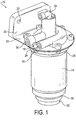
- a filter assembly 10 is used in an air brake system.
- the exemplary filter assembly 10 may include a filter head 12 and a filter housing 14 attached to the filter head 12 via bolts 16 and bolt holes 18 formed in the filter head 12.
- the filter head 12 may be formed of a cast metal and may include a mounting portion 20 with mounting holes 22 that are slotted or round for mounting the filter assembly 10 within a vehicle (not shown).
- the filter head 12 defines a compressed fluid inlet 24 that is in fluid communication with a compressor (not shown) of the vehicle.
- the fluid inlet 24 may be spiral-shaped such that a compressed fluid stream of air containing oil and water enters the filter housing 14 from the fluid inlet 24.
- the filter head 12 also includes a fluid outlet 26 that outputs the filtered fluid, which generally is clean and dry air, from the filter assembly 10 to be used in operation of the brake system (not shown).
- the fluid outlet 26 is in sealed fluid communication with the brake system.
- the filter housing 14 may be tubular with a first end 28 and a second end 30.
- the first end 28 is attachable to the filter head 12 and the second end 30 has a purge port 32 for draining the filtered oil and water from the filter assembly 10.
- the purge port 32 contains a purge assembly (described in more detail below) that is actuated in response to a governor control port 34 located in the filter head 12.
- the governor control port 34 governs the maximum pressure in the filter assembly 10 based on signals sent by the compressor of the vehicle.
- the compressor sends a signal that the amount of pressure entering the filter assembly 10 is at a maximum and the signal is conducted to the governor control port 34.
- the governor control port 34 further is configured to operate a piston that in turn opens the purge valve within the purge assembly.
- the open purge valve allows the fluid to drain from the filter assembly 10 and into the surrounding environment.
- Fig. 2 is a drawing depicting an exploded view of the filter assembly 10 shown in Fig. 1 .
- the filter assembly 10 includes a filter element 36 received in the filter housing 14 for separating the liquid from the compressed fluid.
- the filter element 36 may be a replaceable cartridge-style element, and has a longitudinally extending body of coalescing media 38.
- the filter element 36 may be easily removable from the filter housing 14 for servicing and replacement.
- the filter element 36 is inserted into the filter housing 14 such that the body of fluid is trapped between the filter housing 14 and the body of coalescing media 38.
- the oily and humid air from the body of fluid enters the body of coalescing media 38, allowing oil droplets and moisture to coalesce into larger droplets. As the oil and/or moisture droplets grow in size, the droplets form a layer separable from the fluid.
- the filter element 36 may further include a first end cap 40 having a central body portion 42 that is attachable to the filter head 12 and fixed to a first end 44 of the body of coalescing media 38.
- the first end cap 40 includes a shroud 46 that extends longitudinally from the central body portion 42.
- the shroud 46 has a radially outer annular surface 48 that progressively increases in diameter from a first end 47 toward a second end 49 of the shroud 46.
- the body of coalescing media 38 further includes a second end 50 that is located distally opposite the first end 44.
- the first end 44 is a top end and the second end 50 is a bottom end.
- the annular surface 48 of the shroud 46 may be continuous and flare radially outwardly from the body of coalescing media 38 toward the filter housing 14.
- the shroud 46 is configured to reduce the flow area of the entering stream of compressed fluid from the spiral-shaped fluid inlet 24. The area reduction induces a vortex within the filter housing 14, allowing the liquid to separate from the vortex of air as the vortex of fluid swirls around the body of coalescing media 38.
- the spiral-shaped fluid inlet 24 and the shroud 46 induce the vortex which provides the centrifugal pre-separation of the liquid particles of oil and water. The oil and water are separated from the fluid prior to coalescing and further separated by the coalescing medium prior to desiccation.
- the outer annular surface 48 of the shroud 46 is spaced radially outwardly from the body of coalescing media 38, defining a recess 52 between the outer annular surface 48 and the body of coalescing media 38.
- the recess 52 increases in diameter from the first end 47 of the shroud 46 toward the second end 49 of the shroud.
- the outer annular surface 48 may be convexed in the longitudinal direction.
- the shroud 46 may be mushroom-shaped or frustoconical.
- the shroud 46 also has a planar surface 54 that extends radially outwardly from the central body portion 42 to the outer annular surface 48.
- the planar surface 54 may have at least one axially extending surface 56 that are received within the body of coalescing media 38 for further securing the shroud 46 to the first end 44 of the body of coalescing media 38.
- the axially extending surface 56 may be a wall that is annular. The wall may be thin.
- the axially extending surface 56 may be a plug.
- the body of coalescing media 38 may be tubular.
- the body of coalescing media 38 may be pleated or have any shape suitable for use within the filter assembly 10.
- the body of coalescing media 38 may have an outer wall 58 circumscribing a central cavity 60.
- the filter element 36 further includes a longitudinal desiccant body 62 extending through the central cavity 60 between the first end 44 and the second end 50 of the body of coalescing media 38.
- the desiccant body 62 has a top end at the first end 44 and a bottom end at the second end 50.
- the desiccant body 62 may be surrounded by a steel tube 64.
- the filter element 36 further includes a second end cap 66 at the second end 50 of the body of coalescing media 38 that defines a fluid passage 67.
- the fluid passage 67 allow oil-free air to wrap around a bottom end of the desiccant body 62 and the steel tube to enter the desiccant body 62 at the bottom end of the desiccant body 62. The separated oil does not reach the desiccant body 62.
- the second end cap 66 may further include an axially extending rim 68 that extends from the second end cap 66 within the central cavity 60 for supporting the desiccant body 62, the tube 64, and the elongated valve operator 82 within the body of coalescing media 38.
- the second end cap 66 also includes a purge valve assembly 69 for draining the filtered water and oil from the filter assembly 10.
- the purge valve assembly 69 is housed in the purge port 32 of the filter housing 14 and includes a purge valve 70.
- the purge valve 70 is biassed by a spring 72 to a closed position and is moveable to an open position for draining the liquid.
- the purge valve 70 may be a poppet style valve.
- the purge valve assembly 69 also includes a sump 74 for holding or retaining the liquid within the filter assembly 10 when the purge valve 70 is in the closed position.
- the sump 74 may be cone-shaped. The separated liquid is deposited in the sump 74.
- the purge valve assembly 69 further includes a valve seat 76 defined by the sump 74 against which the purge valve 70 is seated when in the closed position.
- the sump 74 directs the collected oil and water to a mouth of the purge valve 70.
- the second end cap 66 further includes a central body portion 78 in which the purge valve assembly 69 is contained.
- the second end cap 66 also has a radially extending flange 80 for attaching the second end cap 66 to the second end 50 of the body of coalescing media 38.
- the second end cap 66 may also have a snap ring 81 for securing the purge valve assembly 69 within the second end cap 66.
- the purge valve 70 may be actuated by an elongated valve operator 82 that axially extends through the desiccant body 62 between the first end 44 and the second end 50 of the body of coalescing media 38.
- the valve operator 82 is configured to move the purge valve 70 to the open position when the valve operator 82 is depressed.
- the valve operator 82 may protrude from the desiccant body 62 at the second end 50 of the body of coalescing media 38.
- the valve operator 82 engages a head 84 of the purge valve 70 through the second end cap 66 at the second end 50 of the body of coalescing media 38.
- the valve operator 82, the desiccant body 62, and the body of coalescing media 38 may be concentrically positioned about a longitudinal axis of the filter assembly 10.
- valve operator 82 may also protrude from the top end of the desiccant body 62 at the first end 44 of the body of coalescing media 38.
- the valve operator 82 may extend through and further protrude from the central body portion 42 of the first end cap 40.
- the central body portion 42 may define an axially extending chamber 86 that extends into the desiccant body 62.
- the chamber 86 and the desiccant body 62 may be coaxial.
- the valve operator 82 may include a radially extending limit stop 88 that travels within the chamber 86 such that the chamber 86 defines the movement of the valve operator 82.
- the central body portion 42 may define a fluid outlet 90 and at least one outlet passage 92 in fluid communication with the desiccant body 62.
- the at least one outlet passage 92 may include a plurality of outlet passages and allows the filtered and dried air to flow out of the desiccant body 62 and into the fluid outlet 90.
- the fluid outlet 90 may be in fluid communication with the filter head 12 for outputting the filtered air from the filter element 36.
- a filter assembly 10 includes a filter head 12 and a filter housing 14 receiving a filter element 36.
- Fig. 6 shows the entire filter assembly in cross-section, and therefore like components are identified by like reference numerals in Figs. 1-6 .
- the filter head 12 includes a spiral-shaped fluid inlet 24 and a fluid outlet 26. Fluid enters the filter assembly 10 via the fluid inlet 24. The fluid is compressed by a compressor (not shown) that outputs a fluid containing a mixture of air, oil, and water.
- the filter element 36 may be a replaceable element and is cartridge-like for inserting the filter element 36 within the filter housing 14 and removing the filter element 36 for servicing and replacement.
- the filter element 36 has a longitudinally extending body of coalescing media 38 having a first end 44 and a second end 50 distally opposite the first end 44.
- the filter element 36 has a top end cap 40 that has a central body portion 42 fixed to the first end 44 of the body of coalescing media 38.
- the top end cap 40 has a shroud 46 that extends longitudinally from the central body portion 42 and has a radially outer annular surface 48 that progressively increases in diameter from the first end 47 toward the second end 49 of the shroud 46.
- the shroud 46 is configured to reduce a flow area of the entering stream of compressed fluid to induce a vortex of fluid. The vortex swirls around the body of coalescing media 38, between the filter housing 14 and the body of coalescing media 38.
- the body of coalescing media 38 is tubular and has an outer wall circumscribing a central cavity 60.
- a desiccant body 62 extends axially through the central cavity 60 between the first end 44 and the second end 50 of the body of coalescing media 38.
- the separated liquid and filtered air travels within the central cavity 60 from the first end 44 toward the second end 50.
- the filtered air enters the desiccant body 62 at the second end 50 to be dried. Once the filtered air has travelled to the top of the desiccant body 62, the filtered air passes through a plurality of o-ring passages 92 defined in the top end cap 40.
- the filtered air is then outputted from the filter assembly 10 through a fluid outlet 26 having sealed fluid communication with the plurality of o-ring passages 92, to be used in a brake system.
- the fluid outlet 26 may include a check valve assembly (not shown).
- the liquid is drained from the fluid assembly 10 via a purge valve assembly 69 located at the second end 50 of the body of coalescing media 38.
- the purge valve assembly 69 is housed in a purge port 32 of the filter housing 14 and includes a purge valve 70.
- the purge valve 70 is biassed by a spring 72 to a closed position and is moveable to an open position for draining the liquid.
- the purge valve assembly 69 also includes a sump 74 for retaining the liquid within the filter assembly 10 when the purge valve 70 is in the closed position.
- the sump 74 may be cone-shaped.
- the purge valve assembly 69 further includes a valve seat 76 defined by the sump 74 against which the purge valve 70 is seated when in the closed position.
- the purge valve assembly 69 may be contained in a bottom end cap 66 of the filter element 36 located at the second end 50 of the body of coalescing media 38.
- the purge valve 70 is actuatable by an elongated valve operator 82 that axially extends through the desiccant body 62 between the first end 44 and the second end 50 of the body of coalescing media 38.
- the valve operator 82 is configured to move the purge valve 70 to the open position when the valve operator 82 is depressed.
- the valve operator 82 may protrude from the desiccant body 62 at the first end 44 and the second end 50 of the body of coalescing media 38.
- the valve operator 82 engages the head 84 of the purge valve 70 at the second end 50.
- the valve operator 82, the desiccant body 62, and the body of coalescing media 38 may be positioned concentrically about a longitudinal axis of the filter assembly 10.
- the valve operator 82 and the purge valve 70 may also be replaceable when replacing the filter element 36 in the filter assembly 10.
- the valve operator 82 is configured to move the purge valve 70 between the closed position and the open position.
- the valve operator 82 is moveable by an actuating piston 94 located in the filter head 12, distally opposite the purge valve assembly 69.
- the actuating piston 94 moves the purge valve 70 by acting on the valve operator 82, in response to the elevated pressure signal communicated by the compressor (not shown) to the governor control port 34 in the filter assembly 10.
- the filter head 12 includes an atmospheric reference chamber 96 in which the actuating piston is axially moveable and that is separated from the governor control port 34 by the actuating piston 94.
- the elevated pressure acts upon the piston 94.
- the piston 94 is then depressed against the atmospheric reference chamber 96 and a piston return spring 100.
- the piston return spring 100 is compressed with the spring 72 of the purge valve assembly 69.
- the piston return spring 100 returns the piston 94 to its normal position when the pressure signal at the governor control port 34 is removed.
- the piston 94 is depressed to move the valve operator 82 against the force of the return spring 100 and the spring 72 and open the purge valve 70 to drain the liquid from the filter assembly 10.
- a radially extending limit stop 88 limits the return travel of the operator 82.
- the limit stop 88 also retains the operator from unintended removal from the first end cap 40 when the filter element 36 is not installed within the filter assembly 10. The drained liquid is emitted to the surrounding environment of the vehicle.
- the outer annular surface may be spaced radially outwardly from the body of coalescing media or convexed in the longitudinal direction.
- the shroud may be mushroom-shaped or frustoconical.
- the shroud may have a planar surface extending radially outwardly from the central body portion to the outer annular surface.
- the filter element may be inserted into a tubular housing such that the vortex is trapped between the tubular housing and the body of coalescing media.
- the annular surface of the shroud may flare radially outwardly from the body of coalescing media toward the tubular housing.
- the body of coalescing media may be tubular and have an outer wall circumscribing a central cavity.
- the filter element may include a longitudinal desiccant body axially extending through the central cavity.
- the central body portion of the first end cap may define at least one outlet passage in fluid communication with the desiccant body that allows the filtered air to flow out of the desiccant body through the at least one outlet passage.
- the filter element may include a second end cap at the second end of the body of coalescing media that has a purge valve biassed in a closed position that is moveable to an open position to drain the liquid out of the filter assembly.
- the filter element may further include an elongated valve operator axially extending through the body of coalescing media between the first end and the second end. The valve operator may be configured to move the purge valve to the open position when the valve operator is depressed.
- the filter element may be included in a filter assembly that has a spiral-shaped fluid inlet such that the shroud is configured to reduce the flow area of the fluid stream from the fluid inlet into the filter element, to induce the vortex of the fluid.
- a filter element for separating and removing a liquid from a fluid can include a longitudinally extending body of coalescing media for separating the liquid from the fluid having a top end and a bottom end distally opposite the top end, and a purge valve assembly at the bottom end of the body of coalescing media, in which the purge valve assembly has a purge valve biassed in a closed position and moveable to an open position to drain the liquid out of the filter assembly.
- the purge valve assembly may include a sump for holding the liquid when the purge valve is in the closed position, and a valve seat defined by the sump against which the purge valve is seated when in the closed position.
- the filter element may further include an elongated valve operator axially extending through the body of coalescing media between the top end and the bottom end, such that the elongated valve operator is configured to move the purge valve between the closed position and the open position.
- a filter assembly for separating and removing a liquid from a fluid can include a filter head having a fluid inlet and an actuating piston, a longitudinal filter element for separating the liquid from the fluid that has a first end in fluid communication with the fluid inlet and a second end distally opposite the first end, a purge valve at the second end of the filter element distally opposite the filter head that is biassed in a closed position and moveable to an open position for draining the liquid out of the filter assembly, and an elongated valve operator that axially extends through the filter element between the first end and the second end and is configured to move the purge valve between the closed position and the open position.
- the actuating piston is configured to move the purge valve by acting on the valve operator, in response to elevated pressure in the filter assembly.
- the filter head may include an atmospheric reference chamber in which the actuating piston is moveable and that is configured to detect when the filter assembly has elevated pressure.
- the filter head may include a governor pressure chamber that is separated from the atmospheric reference chamber by the actuating piston, such that the piston moves when elevated pressure is communicated to the governor pressure chamber.
- the fluid inlet may be spiral-shaped and the filter element may be configured to reduce a flow area of fluid entering the filter element from the fluid inlet, to induce a vortex of the fluid.
- the filter assembly may include a shroud at the first end of the filter element that extends longitudinally from a first end toward a second end of the shroud and has a radially outer annular surface that progressively increases in diameter from the first end toward the second end of the shroud, such that the shroud is configured to induce the vortex and accelerate a speed of the vortex, allowing the liquid to separate from the vortex.
- the shroud may include at least one outlet passage at the first end of the filter element allowing filtered air to exit the filter element.
- the filter head may include a fluid outlet in fluid communication with the at least one outlet passage at the first end of the filter element.
- the filter element may further include a sump at the second end of the filter element and a valve seat defined by the sump, such that the purge valve is biased against the valve seat when in the closed position.
- the filter element may include a longitudinal body of coalescing media circumscribing a central cavity, and a longitudinal desiccant body within the central cavity.
- the elongated valve operator may extend through the desiccant body and protrudes from the desiccant body at the first end and the second end of the filter element.
Landscapes
- Chemical & Material Sciences (AREA)
- Chemical Kinetics & Catalysis (AREA)
- Engineering & Computer Science (AREA)
- Analytical Chemistry (AREA)
- General Chemical & Material Sciences (AREA)
- Oil, Petroleum & Natural Gas (AREA)
- Transportation (AREA)
- Mechanical Engineering (AREA)
- Physics & Mathematics (AREA)
- Geometry (AREA)
- Drying Of Gases (AREA)
- Filtering Of Dispersed Particles In Gases (AREA)
Claims (13)
- Filterelement (36) zur Anordnung in einem röhrenförmigen Gehäuse einer Filterbaugruppe, das eine Flüssigkeit aus einem komprimierten Fluidstrom abscheidet, welcher in die Filterbaugruppe strömt, das Filterelement umfassend:einen längs verlaufenden Körper aus Koaleszenzmedien (38) mit einem ersten Ende und einem zweiten, dem ersten Ende distal gegenüberliegenden Ende, undeine erste Endkappe (40) mit einem mittigen Körperabschnitt (42), der am ersten Ende (44) des Körpers aus Koaleszenzmedien befestigt ist,dadurch gekennzeichnet, dass das Filterelement ein Verkleidungselement (46) enthält, das längs vom mittigen Körperabschnitt verläuft und eine radial äußere ringförmige Oberfläche (48) aufweist, welche fortschreitend im Durchmesser von einem ersten Ende des Verkleidungselements zu einem zweiten Ende (49) des Verkleidungselements in einer Richtung zum zweiten Ende (49) des Körpers aus Koaleszenzmedien hin zunimmt, wobei das Verkleidungselement zum Vermindern eines Strombereichs des Fluidstroms konfiguriert ist, der in den Raum innerhalb der Filterbaugruppe zwischen der Wand des Filterelements, die durch den Körper aus Koaleszenzmedien vorgesehen ist, und der Innenwand eines Gehäuses (14) strömt, in welchem sich das Filterelement befindet, wenn es in Gebrauch ist, um einen Wirbel des Fluids um den Körper aus Koaleszenzmedien einzuleiten, wodurch ermöglicht wird, dass sich die Flüssigkeit aus dem Wirbel abscheidet, bevor das Fluid den Körper aus Koaleszenzmedien durchläuft.
- Filterelement nach Anspruch 1, wobei das Verkleidungselement (46) pilzförmig oder kegelstumpfförmig ist und die äußere ringförmige Oberfläche (48) radial nach außen vom Körper aus Koaleszenzmedien (38) beabstandet ist und vorzugsweise in der Längsrichtung konvex ist.
- Filterelement nach Anspruch 1 oder 2, wobei das Verkleidungselement (46) eine plane Oberfläche (54) aufweist, die radial nach außen vom mittigen Körperabschnitt (42) der ersten Endkappe zur äußeren ringförmigen Oberfläche (48) verläuft.
- Filterelement nach einem der vorhergehenden Ansprüche, welches einen längs verlaufenden Sikkativkörper (62) enthält, der axial durch den Körper aus Koaleszenzmedien (38) verläuft, wobei
der Körper aus Koaleszenzmedien vorzugsweise röhrenförmig ist und eine Außenwand (58) aufweist, die einen mittigen Hohlraum (60) abgrenzt, durch welchen der Sikkativkörper verläuft. - Filterelement nach Anspruch 4, wobei der mittige Körperabschnitt (42) der ersten Endkappe (40) zumindest einen Auslassdurchgang in Fluidverbindung mit dem Sikkativkörper (62) definiert, der ermöglicht, dass gefilterte Luft aus dem Sikkativkörper durch den zumindest einen Ablassdurchgang strömt.
- Filterelement nach einem der vorhergehenden Ansprüche, welches eine zweite Endkappe (66) am zweiten Ende (50) des Körpers aus Koaleszenzmedien (38) mit einem Spülluftventil (70) enthält, das in einer geschlossenen Position vorgespannt ist und zum Entleeren von Flüssigkeit aus der Filterbaugruppe in eine offene Position beweglich ist.
- Filterelement nach Anspruch 6, welches eine gestreckte Ventilbetätigungseinrichtung (82) enthält, die axial durch den Körper aus Koaleszenzmedien (38) zwischen dem ersten Ende (44) und dem zweiten Ende (50) verläuft, wobei die Ventilbetätigungseinrichtung zum Bewegen des Spülluftventils (70) in die offene Position konfiguriert ist, wenn die Ventilbetätigungseinrichtung gedrückt wird.
- Filterbaugruppe, umfassend:das Filterelement (36) nach einem der Ansprüche 1 bis 7, undein röhrenförmiges Gehäuse (14), wobei das Filterelement in das röhrenförmige Gehäuse eingefügt ist und der Wirbel zwischen dem röhrenförmigen Gehäuse und dem Körper aus Koaleszenzmedien (38) gefangen ist, und wobei sich die ringförmige Oberfläche (48) des Verkleidungselements (46) radial nach außen vom Körper aus Koaleszenzmedien (38) zum röhrenförmigen Gehäuse hin aufweitet.
- Filterbaugruppe, umfassend:das Filterelement (36) nach einem der Ansprüche 1 bis 7, undeinen spiralförmigen Fluideinlass (24), wobei das Verkleidungselement (46) zum Vermindern des Strombereichs des Fluidstroms vom Fluideinlass in das Filterelement konfiguriert ist, um den Wirbel des Fluids einzuleiten.
- Filterelement nach einem der Ansprüche 1 bis 7, wobei das erste Ende (44) des Körpers aus Koaleszenzmedien (38) ein oberes Ende ist und das zweite Ende (50) des Körpers ein unteres Ende ist, und welches eine Spülluftventilbaugruppe (69) am unteren Ende des Körpers aus Koaleszenzmedien enthält, wobei die Spülluftventilbaugruppe ein Spülluftventil (70), das in einer geschlossenen Position vorgespannt ist und zum Entleeren von Flüssigkeit aus der Filterbaugruppe beweglich ist, einen Sammelbehälter (74) zum Enthalten der Flüssigkeit, wenn das Spülluftventil in der geschlossenen Position ist, und einen Ventilsitz (76) aufweist, der durch den Sammelbehälter, an dem das Spülluftventil sitzt, wenn es in der geschlossenen Position ist, definiert ist.
- Filterbaugruppe zum Abscheiden und Entfernen einer Flüssigkeit aus einem Fluid, umfassend:einen Filterkopf (12) mit einem Fluideinlass (24) und einem Betätigungskolben (94), undein Filterelement (36) nach einem der Ansprüche 1 bis 7.
- Filterbaugruppe nach Anspruch 11, wobei der Filterkopf (12) eine atmosphärische Referenzkammer (96) und eine Druckreglerkammer enthält, die durch den Betätigungskolben (94) getrennt sind, wobei der Betätigungskolben innerhalb der atmosphärischen Referenzkammer beweglich ist, wenn der Druckreglerkammer erhöhter Druck vermittelt wird.
- Filterbaugruppe nach Anspruch 11 oder 12, wobei der Fluideinlass (12) spiralförmig ist und das Filterelement (36) zum Vermindern eines Strombereichs von Fluid, das vom Fluideinlass in das Filterelement eintritt, konfiguriert ist, um einen Wirbel des Fluids einzuleiten.
Priority Applications (1)
| Application Number | Priority Date | Filing Date | Title |
|---|---|---|---|
| EP19201319.1A EP3617016B1 (de) | 2014-10-28 | 2015-10-27 | Kombinierter öl- und wasserabscheider in einem luftbremsentrockner |
Applications Claiming Priority (1)
| Application Number | Priority Date | Filing Date | Title |
|---|---|---|---|
| US201462069380P | 2014-10-28 | 2014-10-28 |
Related Child Applications (2)
| Application Number | Title | Priority Date | Filing Date |
|---|---|---|---|
| EP19201319.1A Division-Into EP3617016B1 (de) | 2014-10-28 | 2015-10-27 | Kombinierter öl- und wasserabscheider in einem luftbremsentrockner |
| EP19201319.1A Division EP3617016B1 (de) | 2014-10-28 | 2015-10-27 | Kombinierter öl- und wasserabscheider in einem luftbremsentrockner |
Publications (2)
| Publication Number | Publication Date |
|---|---|
| EP3018021A1 EP3018021A1 (de) | 2016-05-11 |
| EP3018021B1 true EP3018021B1 (de) | 2019-12-04 |
Family
ID=54364119
Family Applications (2)
| Application Number | Title | Priority Date | Filing Date |
|---|---|---|---|
| EP19201319.1A Active EP3617016B1 (de) | 2014-10-28 | 2015-10-27 | Kombinierter öl- und wasserabscheider in einem luftbremsentrockner |
| EP15191744.0A Active EP3018021B1 (de) | 2014-10-28 | 2015-10-27 | Kombinierter öl- und wasserabscheider in einem luftbremsentrockner |
Family Applications Before (1)
| Application Number | Title | Priority Date | Filing Date |
|---|---|---|---|
| EP19201319.1A Active EP3617016B1 (de) | 2014-10-28 | 2015-10-27 | Kombinierter öl- und wasserabscheider in einem luftbremsentrockner |
Country Status (2)
| Country | Link |
|---|---|
| US (3) | US10183658B2 (de) |
| EP (2) | EP3617016B1 (de) |
Families Citing this family (7)
| Publication number | Priority date | Publication date | Assignee | Title |
|---|---|---|---|---|
| CN107192053A (zh) * | 2017-07-14 | 2017-09-22 | 芜湖威灵数码科技有限公司 | 一种家庭用空气净化器 |
| US10583382B2 (en) * | 2017-10-04 | 2020-03-10 | Bendix Commercial Vehicle Systems Llc | Effluent processing apparatus for a vehicle air brake charging system |
| SE541945C2 (sv) * | 2017-10-25 | 2020-01-07 | Thordab Ind Ab | Avfuktningsanordning |
| US10807582B2 (en) * | 2018-03-27 | 2020-10-20 | Bendix Commercial Vehicle Systems Llc | Effluent processing apparatus and method for a vehicle air brake charging system |
| CN108547805B (zh) * | 2018-06-22 | 2023-08-29 | 高先乐 | 油箱呼吸器及油箱 |
| DE102020122652A1 (de) | 2020-08-31 | 2022-03-03 | Beko Technologies Gmbh | Druckgasfilter mit Durchgangsöffnung im Gehäusekopf |
| FR3135626B1 (fr) * | 2022-05-17 | 2024-04-12 | Sogefi Filtration Spa | Cartouche filtrante à effet déshydratant et dispositif de filtration pour lubrifiant incluant la cartouche |
Family Cites Families (18)
| Publication number | Priority date | Publication date | Assignee | Title |
|---|---|---|---|---|
| US2942691A (en) * | 1956-09-27 | 1960-06-28 | Watts Regulator Co | Air line filter |
| US3257783A (en) * | 1963-04-03 | 1966-06-28 | Wilkerson Corp | Filter and automatic dump valve for pressure fluid lines |
| FR2224211A1 (en) * | 1973-04-05 | 1974-10-31 | Fermat Sa | Centrifugal gas filter - sepg solid and liq. particles from gas flow with low pressure drop |
| US4487617A (en) * | 1983-08-22 | 1984-12-11 | The Bendix Corporation | Mechanism for cleaning and drying compressed gases |
| GB8700803D0 (en) * | 1987-01-15 | 1987-02-18 | Bendix Ltd | Gas drying apparatus |
| US5427609A (en) * | 1993-09-14 | 1995-06-27 | Horton Industries, Inc. | Device for cleaning and drying compressed gas |
| WO1995007745A1 (en) * | 1993-09-15 | 1995-03-23 | Parker Hannifin Corporation | Fuel filter element |
| US6641633B2 (en) | 2001-04-23 | 2003-11-04 | Julian L. Witengier | Gas/liquid separator for a pneumatic line |
| US6730143B1 (en) | 2002-11-18 | 2004-05-04 | Bendix Commercial Vehicle Systems, Llc | Truck air dryer purge air cleaner |
| JP2007529312A (ja) | 2004-03-19 | 2007-10-25 | イリノイ トゥール ワークス インコーポレイティド | 使捨てカートリッジ型空気/ガスドライヤー |
| DE102005039059B3 (de) * | 2005-08-18 | 2006-09-28 | Haldex Brake Products Gmbh | Kartusche zum Reinigen von Druckluft in Druckluftbeschaffungsanlagen von Kraftfahrzeugen |
| WO2008106587A1 (en) * | 2007-02-28 | 2008-09-04 | Stoneridge, Inc. | Filtration device for use with a fuel vapor recovery system |
| DE102008026103A1 (de) * | 2008-05-30 | 2009-12-03 | Knorr-Bremse Systeme für Nutzfahrzeuge GmbH | Lufttrockner mit integrierter Regenerationssteuerung und Verfahren zum Betreiben eines Lufttrockners |
| DE102009030897B4 (de) | 2009-06-29 | 2015-02-26 | Knorr-Bremse Systeme für Nutzfahrzeuge GmbH | Lufttrocknerpatrone für eine Druckluftaufbereitungsanlage eines Fahrzeugs und Druckluftaufbereitungsanlage für ein Fahrzeug mit einer entsprechenden Lufttrocknerpatrone. |
| DE102010010882B4 (de) | 2010-03-10 | 2021-10-21 | Knorr-Bremse Systeme für Nutzfahrzeuge GmbH | Lufttrocknerpatrone und Verfahren zum Betreiben einer Lufttrocknerpatrone |
| US8850013B2 (en) | 2010-05-10 | 2014-09-30 | Jaron Waldman | Server load balancing using geodata |
| US8557030B2 (en) | 2011-04-06 | 2013-10-15 | Bendix Commercial Vehicle Systems Llc | Air dryer assembly |
| CN202129015U (zh) * | 2011-07-08 | 2012-02-01 | 瑞立集团瑞安汽车零部件有限公司 | 集成式空气干燥筒、压缩空气制动系统及车辆 |
-
2015
- 2015-10-27 EP EP19201319.1A patent/EP3617016B1/de active Active
- 2015-10-27 EP EP15191744.0A patent/EP3018021B1/de active Active
- 2015-10-28 US US14/925,002 patent/US10183658B2/en active Active
-
2018
- 2018-12-12 US US16/217,074 patent/US10625727B2/en active Active
-
2020
- 2020-03-11 US US16/815,187 patent/US20200207324A1/en not_active Abandoned
Non-Patent Citations (1)
| Title |
|---|
| None * |
Also Published As
| Publication number | Publication date |
|---|---|
| US10625727B2 (en) | 2020-04-21 |
| EP3617016B1 (de) | 2021-03-10 |
| US20200207324A1 (en) | 2020-07-02 |
| EP3617016A1 (de) | 2020-03-04 |
| US10183658B2 (en) | 2019-01-22 |
| EP3018021A1 (de) | 2016-05-11 |
| US20160114777A1 (en) | 2016-04-28 |
| US20190111905A1 (en) | 2019-04-18 |
Similar Documents
| Publication | Publication Date | Title |
|---|---|---|
| EP3018021B1 (de) | Kombinierter öl- und wasserabscheider in einem luftbremsentrockner | |
| JP7336103B2 (ja) | 濾過デバイスおよびブレーキダストを分離し収集するための当該デバイスの使用法 | |
| US7727313B2 (en) | Air dryer | |
| CN101175549B (zh) | 空气干燥器筒体 | |
| US4692175A (en) | Two-stage precoalescer unit | |
| US6730143B1 (en) | Truck air dryer purge air cleaner | |
| KR101509099B1 (ko) | 오일 증기 분리기 | |
| US8500885B2 (en) | Air drier for air suspension of vehicle | |
| US8876961B2 (en) | Particle separator with deflector and lateral opening and air filter system | |
| HUT72524A (en) | Apparatus for the separation of the oil dust from air | |
| JP2003507172A (ja) | 圧縮空気系用バイパスを有する油分離器 | |
| CN108136295A (zh) | 过滤器插入件和过滤器设备 | |
| CA2499446A1 (en) | Filter with thermal vent | |
| CN113613973A (zh) | 分离装置以及用于分离和收集制动灰尘的装置的用途 | |
| CN1327937C (zh) | 带有整体除油过滤器的离心式干燥剂滤筒 | |
| US11247152B2 (en) | Filter insert and a filter arrangement | |
| JP6949904B2 (ja) | オイルセパレータ | |
| JP2008302342A (ja) | サイクロン式オイルセパレータおよびそれを備えた汚泥回収車 | |
| JP6639864B2 (ja) | 気液分離装置 |
Legal Events
| Date | Code | Title | Description |
|---|---|---|---|
| PUAI | Public reference made under article 153(3) epc to a published international application that has entered the european phase |
Free format text: ORIGINAL CODE: 0009012 |
|
| AK | Designated contracting states |
Kind code of ref document: A1 Designated state(s): AL AT BE BG CH CY CZ DE DK EE ES FI FR GB GR HR HU IE IS IT LI LT LU LV MC MK MT NL NO PL PT RO RS SE SI SK SM TR |
|
| AX | Request for extension of the european patent |
Extension state: BA ME |
|
| STAA | Information on the status of an ep patent application or granted ep patent |
Free format text: STATUS: REQUEST FOR EXAMINATION WAS MADE |
|
| 17P | Request for examination filed |
Effective date: 20161110 |
|
| RBV | Designated contracting states (corrected) |
Designated state(s): AL AT BE BG CH CY CZ DE DK EE ES FI FR GB GR HR HU IE IS IT LI LT LU LV MC MK MT NL NO PL PT RO RS SE SI SK SM TR |
|
| RIC1 | Information provided on ipc code assigned before grant |
Ipc: B01D 53/04 20060101ALI20190425BHEP Ipc: B60T 17/00 20060101AFI20190425BHEP Ipc: B01D 53/26 20060101ALI20190425BHEP Ipc: F15B 21/04 20190101ALI20190425BHEP |
|
| GRAP | Despatch of communication of intention to grant a patent |
Free format text: ORIGINAL CODE: EPIDOSNIGR1 |
|
| STAA | Information on the status of an ep patent application or granted ep patent |
Free format text: STATUS: GRANT OF PATENT IS INTENDED |
|
| INTG | Intention to grant announced |
Effective date: 20190607 |
|
| GRAS | Grant fee paid |
Free format text: ORIGINAL CODE: EPIDOSNIGR3 |
|
| GRAA | (expected) grant |
Free format text: ORIGINAL CODE: 0009210 |
|
| STAA | Information on the status of an ep patent application or granted ep patent |
Free format text: STATUS: THE PATENT HAS BEEN GRANTED |
|
| AK | Designated contracting states |
Kind code of ref document: B1 Designated state(s): AL AT BE BG CH CY CZ DE DK EE ES FI FR GB GR HR HU IE IS IT LI LT LU LV MC MK MT NL NO PL PT RO RS SE SI SK SM TR |
|
| REG | Reference to a national code |
Ref country code: GB Ref legal event code: FG4D |
|
| REG | Reference to a national code |
Ref country code: CH Ref legal event code: EP |
|
| REG | Reference to a national code |
Ref country code: AT Ref legal event code: REF Ref document number: 1209017 Country of ref document: AT Kind code of ref document: T Effective date: 20191215 |
|
| REG | Reference to a national code |
Ref country code: DE Ref legal event code: R096 Ref document number: 602015042875 Country of ref document: DE |
|
| REG | Reference to a national code |
Ref country code: IE Ref legal event code: FG4D |
|
| REG | Reference to a national code |
Ref country code: NL Ref legal event code: MP Effective date: 20191204 |
|
| REG | Reference to a national code |
Ref country code: LT Ref legal event code: MG4D |
|
| PG25 | Lapsed in a contracting state [announced via postgrant information from national office to epo] |
Ref country code: FI Free format text: LAPSE BECAUSE OF FAILURE TO SUBMIT A TRANSLATION OF THE DESCRIPTION OR TO PAY THE FEE WITHIN THE PRESCRIBED TIME-LIMIT Effective date: 20191204 Ref country code: GR Free format text: LAPSE BECAUSE OF FAILURE TO SUBMIT A TRANSLATION OF THE DESCRIPTION OR TO PAY THE FEE WITHIN THE PRESCRIBED TIME-LIMIT Effective date: 20200305 Ref country code: NO Free format text: LAPSE BECAUSE OF FAILURE TO SUBMIT A TRANSLATION OF THE DESCRIPTION OR TO PAY THE FEE WITHIN THE PRESCRIBED TIME-LIMIT Effective date: 20200304 Ref country code: LT Free format text: LAPSE BECAUSE OF FAILURE TO SUBMIT A TRANSLATION OF THE DESCRIPTION OR TO PAY THE FEE WITHIN THE PRESCRIBED TIME-LIMIT Effective date: 20191204 Ref country code: LV Free format text: LAPSE BECAUSE OF FAILURE TO SUBMIT A TRANSLATION OF THE DESCRIPTION OR TO PAY THE FEE WITHIN THE PRESCRIBED TIME-LIMIT Effective date: 20191204 Ref country code: SE Free format text: LAPSE BECAUSE OF FAILURE TO SUBMIT A TRANSLATION OF THE DESCRIPTION OR TO PAY THE FEE WITHIN THE PRESCRIBED TIME-LIMIT Effective date: 20191204 Ref country code: BG Free format text: LAPSE BECAUSE OF FAILURE TO SUBMIT A TRANSLATION OF THE DESCRIPTION OR TO PAY THE FEE WITHIN THE PRESCRIBED TIME-LIMIT Effective date: 20200304 |
|
| PG25 | Lapsed in a contracting state [announced via postgrant information from national office to epo] |
Ref country code: RS Free format text: LAPSE BECAUSE OF FAILURE TO SUBMIT A TRANSLATION OF THE DESCRIPTION OR TO PAY THE FEE WITHIN THE PRESCRIBED TIME-LIMIT Effective date: 20191204 Ref country code: HR Free format text: LAPSE BECAUSE OF FAILURE TO SUBMIT A TRANSLATION OF THE DESCRIPTION OR TO PAY THE FEE WITHIN THE PRESCRIBED TIME-LIMIT Effective date: 20191204 |
|
| PG25 | Lapsed in a contracting state [announced via postgrant information from national office to epo] |
Ref country code: AL Free format text: LAPSE BECAUSE OF FAILURE TO SUBMIT A TRANSLATION OF THE DESCRIPTION OR TO PAY THE FEE WITHIN THE PRESCRIBED TIME-LIMIT Effective date: 20191204 |
|
| PG25 | Lapsed in a contracting state [announced via postgrant information from national office to epo] |
Ref country code: ES Free format text: LAPSE BECAUSE OF FAILURE TO SUBMIT A TRANSLATION OF THE DESCRIPTION OR TO PAY THE FEE WITHIN THE PRESCRIBED TIME-LIMIT Effective date: 20191204 Ref country code: PT Free format text: LAPSE BECAUSE OF FAILURE TO SUBMIT A TRANSLATION OF THE DESCRIPTION OR TO PAY THE FEE WITHIN THE PRESCRIBED TIME-LIMIT Effective date: 20200429 Ref country code: EE Free format text: LAPSE BECAUSE OF FAILURE TO SUBMIT A TRANSLATION OF THE DESCRIPTION OR TO PAY THE FEE WITHIN THE PRESCRIBED TIME-LIMIT Effective date: 20191204 Ref country code: NL Free format text: LAPSE BECAUSE OF FAILURE TO SUBMIT A TRANSLATION OF THE DESCRIPTION OR TO PAY THE FEE WITHIN THE PRESCRIBED TIME-LIMIT Effective date: 20191204 Ref country code: CZ Free format text: LAPSE BECAUSE OF FAILURE TO SUBMIT A TRANSLATION OF THE DESCRIPTION OR TO PAY THE FEE WITHIN THE PRESCRIBED TIME-LIMIT Effective date: 20191204 Ref country code: RO Free format text: LAPSE BECAUSE OF FAILURE TO SUBMIT A TRANSLATION OF THE DESCRIPTION OR TO PAY THE FEE WITHIN THE PRESCRIBED TIME-LIMIT Effective date: 20191204 |
|
| PG25 | Lapsed in a contracting state [announced via postgrant information from national office to epo] |
Ref country code: SK Free format text: LAPSE BECAUSE OF FAILURE TO SUBMIT A TRANSLATION OF THE DESCRIPTION OR TO PAY THE FEE WITHIN THE PRESCRIBED TIME-LIMIT Effective date: 20191204 Ref country code: IS Free format text: LAPSE BECAUSE OF FAILURE TO SUBMIT A TRANSLATION OF THE DESCRIPTION OR TO PAY THE FEE WITHIN THE PRESCRIBED TIME-LIMIT Effective date: 20200404 Ref country code: SM Free format text: LAPSE BECAUSE OF FAILURE TO SUBMIT A TRANSLATION OF THE DESCRIPTION OR TO PAY THE FEE WITHIN THE PRESCRIBED TIME-LIMIT Effective date: 20191204 |
|
| REG | Reference to a national code |
Ref country code: DE Ref legal event code: R097 Ref document number: 602015042875 Country of ref document: DE |
|
| REG | Reference to a national code |
Ref country code: AT Ref legal event code: MK05 Ref document number: 1209017 Country of ref document: AT Kind code of ref document: T Effective date: 20191204 |
|
| PLBE | No opposition filed within time limit |
Free format text: ORIGINAL CODE: 0009261 |
|
| STAA | Information on the status of an ep patent application or granted ep patent |
Free format text: STATUS: NO OPPOSITION FILED WITHIN TIME LIMIT |
|
| PG25 | Lapsed in a contracting state [announced via postgrant information from national office to epo] |
Ref country code: DK Free format text: LAPSE BECAUSE OF FAILURE TO SUBMIT A TRANSLATION OF THE DESCRIPTION OR TO PAY THE FEE WITHIN THE PRESCRIBED TIME-LIMIT Effective date: 20191204 |
|
| 26N | No opposition filed |
Effective date: 20200907 |
|
| PG25 | Lapsed in a contracting state [announced via postgrant information from national office to epo] |
Ref country code: PL Free format text: LAPSE BECAUSE OF FAILURE TO SUBMIT A TRANSLATION OF THE DESCRIPTION OR TO PAY THE FEE WITHIN THE PRESCRIBED TIME-LIMIT Effective date: 20191204 Ref country code: SI Free format text: LAPSE BECAUSE OF FAILURE TO SUBMIT A TRANSLATION OF THE DESCRIPTION OR TO PAY THE FEE WITHIN THE PRESCRIBED TIME-LIMIT Effective date: 20191204 Ref country code: AT Free format text: LAPSE BECAUSE OF FAILURE TO SUBMIT A TRANSLATION OF THE DESCRIPTION OR TO PAY THE FEE WITHIN THE PRESCRIBED TIME-LIMIT Effective date: 20191204 |
|
| PG25 | Lapsed in a contracting state [announced via postgrant information from national office to epo] |
Ref country code: IT Free format text: LAPSE BECAUSE OF FAILURE TO SUBMIT A TRANSLATION OF THE DESCRIPTION OR TO PAY THE FEE WITHIN THE PRESCRIBED TIME-LIMIT Effective date: 20191204 |
|
| REG | Reference to a national code |
Ref country code: CH Ref legal event code: PL |
|
| PG25 | Lapsed in a contracting state [announced via postgrant information from national office to epo] |
Ref country code: MC Free format text: LAPSE BECAUSE OF FAILURE TO SUBMIT A TRANSLATION OF THE DESCRIPTION OR TO PAY THE FEE WITHIN THE PRESCRIBED TIME-LIMIT Effective date: 20191204 Ref country code: LU Free format text: LAPSE BECAUSE OF NON-PAYMENT OF DUE FEES Effective date: 20201027 |
|
| REG | Reference to a national code |
Ref country code: BE Ref legal event code: MM Effective date: 20201031 |
|
| PG25 | Lapsed in a contracting state [announced via postgrant information from national office to epo] |
Ref country code: LI Free format text: LAPSE BECAUSE OF NON-PAYMENT OF DUE FEES Effective date: 20201031 Ref country code: CH Free format text: LAPSE BECAUSE OF NON-PAYMENT OF DUE FEES Effective date: 20201031 Ref country code: BE Free format text: LAPSE BECAUSE OF NON-PAYMENT OF DUE FEES Effective date: 20201031 |
|
| PG25 | Lapsed in a contracting state [announced via postgrant information from national office to epo] |
Ref country code: IE Free format text: LAPSE BECAUSE OF NON-PAYMENT OF DUE FEES Effective date: 20201027 |
|
| PG25 | Lapsed in a contracting state [announced via postgrant information from national office to epo] |
Ref country code: TR Free format text: LAPSE BECAUSE OF FAILURE TO SUBMIT A TRANSLATION OF THE DESCRIPTION OR TO PAY THE FEE WITHIN THE PRESCRIBED TIME-LIMIT Effective date: 20191204 Ref country code: MT Free format text: LAPSE BECAUSE OF FAILURE TO SUBMIT A TRANSLATION OF THE DESCRIPTION OR TO PAY THE FEE WITHIN THE PRESCRIBED TIME-LIMIT Effective date: 20191204 Ref country code: CY Free format text: LAPSE BECAUSE OF FAILURE TO SUBMIT A TRANSLATION OF THE DESCRIPTION OR TO PAY THE FEE WITHIN THE PRESCRIBED TIME-LIMIT Effective date: 20191204 |
|
| PG25 | Lapsed in a contracting state [announced via postgrant information from national office to epo] |
Ref country code: MK Free format text: LAPSE BECAUSE OF FAILURE TO SUBMIT A TRANSLATION OF THE DESCRIPTION OR TO PAY THE FEE WITHIN THE PRESCRIBED TIME-LIMIT Effective date: 20191204 |
|
| P01 | Opt-out of the competence of the unified patent court (upc) registered |
Effective date: 20230524 |
|
| PGFP | Annual fee paid to national office [announced via postgrant information from national office to epo] |
Ref country code: GB Payment date: 20231027 Year of fee payment: 9 |
|
| PGFP | Annual fee paid to national office [announced via postgrant information from national office to epo] |
Ref country code: FR Payment date: 20231025 Year of fee payment: 9 Ref country code: DE Payment date: 20231027 Year of fee payment: 9 |