EP2192814A1 - Station de base sans fil et son procédé de commande - Google Patents
Station de base sans fil et son procédé de commande Download PDFInfo
- Publication number
- EP2192814A1 EP2192814A1 EP07807076A EP07807076A EP2192814A1 EP 2192814 A1 EP2192814 A1 EP 2192814A1 EP 07807076 A EP07807076 A EP 07807076A EP 07807076 A EP07807076 A EP 07807076A EP 2192814 A1 EP2192814 A1 EP 2192814A1
- Authority
- EP
- European Patent Office
- Prior art keywords
- antenna
- mobile station
- reception
- base station
- signal
- Prior art date
- Legal status (The legal status is an assumption and is not a legal conclusion. Google has not performed a legal analysis and makes no representation as to the accuracy of the status listed.)
- Withdrawn
Links
- 238000000034 method Methods 0.000 title claims description 23
- 230000008054 signal transmission Effects 0.000 claims abstract description 24
- 238000012545 processing Methods 0.000 abstract description 7
- 230000005540 biological transmission Effects 0.000 description 25
- 102100032533 ADP/ATP translocase 1 Human genes 0.000 description 19
- 101000768061 Escherichia phage P1 Antirepressor protein 1 Proteins 0.000 description 19
- 101000796932 Homo sapiens ADP/ATP translocase 1 Proteins 0.000 description 19
- 102100026396 ADP/ATP translocase 2 Human genes 0.000 description 17
- 101000718417 Homo sapiens ADP/ATP translocase 2 Proteins 0.000 description 17
- 239000008186 active pharmaceutical agent Substances 0.000 description 15
- 238000004891 communication Methods 0.000 description 12
- 101100229953 Saccharomyces cerevisiae (strain ATCC 204508 / S288c) SCT1 gene Proteins 0.000 description 10
- 101100194362 Schizosaccharomyces pombe (strain 972 / ATCC 24843) res1 gene Proteins 0.000 description 10
- 238000010586 diagram Methods 0.000 description 10
- 238000010295 mobile communication Methods 0.000 description 6
- 230000008569 process Effects 0.000 description 6
- 230000000694 effects Effects 0.000 description 3
- 238000012986 modification Methods 0.000 description 3
- 230000004048 modification Effects 0.000 description 3
- 239000013307 optical fiber Substances 0.000 description 3
- 230000007423 decrease Effects 0.000 description 2
- 230000003247 decreasing effect Effects 0.000 description 2
- 230000007704 transition Effects 0.000 description 2
- 101710103970 ADP,ATP carrier protein Proteins 0.000 description 1
- 101710133192 ADP,ATP carrier protein, mitochondrial Proteins 0.000 description 1
- 238000013459 approach Methods 0.000 description 1
- 230000008859 change Effects 0.000 description 1
- 238000013461 design Methods 0.000 description 1
- 230000006872 improvement Effects 0.000 description 1
- 238000005259 measurement Methods 0.000 description 1
Images


Classifications
-
- H—ELECTRICITY
- H04—ELECTRIC COMMUNICATION TECHNIQUE
- H04W—WIRELESS COMMUNICATION NETWORKS
- H04W16/00—Network planning, e.g. coverage or traffic planning tools; Network deployment, e.g. resource partitioning or cells structures
- H04W16/24—Cell structures
-
- H—ELECTRICITY
- H01—ELECTRIC ELEMENTS
- H01Q—ANTENNAS, i.e. RADIO AERIALS
- H01Q1/00—Details of, or arrangements associated with, antennas
- H01Q1/12—Supports; Mounting means
- H01Q1/22—Supports; Mounting means by structural association with other equipment or articles
- H01Q1/24—Supports; Mounting means by structural association with other equipment or articles with receiving set
- H01Q1/241—Supports; Mounting means by structural association with other equipment or articles with receiving set used in mobile communications, e.g. GSM
- H01Q1/246—Supports; Mounting means by structural association with other equipment or articles with receiving set used in mobile communications, e.g. GSM specially adapted for base stations
-
- H—ELECTRICITY
- H04—ELECTRIC COMMUNICATION TECHNIQUE
- H04B—TRANSMISSION
- H04B7/00—Radio transmission systems, i.e. using radiation field
- H04B7/02—Diversity systems; Multi-antenna system, i.e. transmission or reception using multiple antennas
- H04B7/04—Diversity systems; Multi-antenna system, i.e. transmission or reception using multiple antennas using two or more spaced independent antennas
- H04B7/06—Diversity systems; Multi-antenna system, i.e. transmission or reception using multiple antennas using two or more spaced independent antennas at the transmitting station
- H04B7/0602—Diversity systems; Multi-antenna system, i.e. transmission or reception using multiple antennas using two or more spaced independent antennas at the transmitting station using antenna switching
- H04B7/0608—Antenna selection according to transmission parameters
-
- H—ELECTRICITY
- H04—ELECTRIC COMMUNICATION TECHNIQUE
- H04W—WIRELESS COMMUNICATION NETWORKS
- H04W36/00—Hand-off or reselection arrangements
- H04W36/24—Reselection being triggered by specific parameters
- H04W36/32—Reselection being triggered by specific parameters by location or mobility data, e.g. speed data
- H04W36/326—Reselection being triggered by specific parameters by location or mobility data, e.g. speed data by proximity to another entity
-
- H—ELECTRICITY
- H04—ELECTRIC COMMUNICATION TECHNIQUE
- H04B—TRANSMISSION
- H04B7/00—Radio transmission systems, i.e. using radiation field
- H04B7/02—Diversity systems; Multi-antenna system, i.e. transmission or reception using multiple antennas
- H04B7/04—Diversity systems; Multi-antenna system, i.e. transmission or reception using multiple antennas using two or more spaced independent antennas
- H04B7/08—Diversity systems; Multi-antenna system, i.e. transmission or reception using multiple antennas using two or more spaced independent antennas at the receiving station
- H04B7/0802—Diversity systems; Multi-antenna system, i.e. transmission or reception using multiple antennas using two or more spaced independent antennas at the receiving station using antenna selection
- H04B7/0805—Diversity systems; Multi-antenna system, i.e. transmission or reception using multiple antennas using two or more spaced independent antennas at the receiving station using antenna selection with single receiver and antenna switching
-
- H—ELECTRICITY
- H04—ELECTRIC COMMUNICATION TECHNIQUE
- H04W—WIRELESS COMMUNICATION NETWORKS
- H04W24/00—Supervisory, monitoring or testing arrangements
- H04W24/10—Scheduling measurement reports ; Arrangements for measurement reports
-
- H—ELECTRICITY
- H04—ELECTRIC COMMUNICATION TECHNIQUE
- H04W—WIRELESS COMMUNICATION NETWORKS
- H04W64/00—Locating users or terminals or network equipment for network management purposes, e.g. mobility management
- H04W64/006—Locating users or terminals or network equipment for network management purposes, e.g. mobility management with additional information processing, e.g. for direction or speed determination
-
- H—ELECTRICITY
- H04—ELECTRIC COMMUNICATION TECHNIQUE
- H04W—WIRELESS COMMUNICATION NETWORKS
- H04W84/00—Network topologies
- H04W84/005—Moving wireless networks
-
- H—ELECTRICITY
- H04—ELECTRIC COMMUNICATION TECHNIQUE
- H04W—WIRELESS COMMUNICATION NETWORKS
- H04W88/00—Devices specially adapted for wireless communication networks, e.g. terminals, base stations or access point devices
- H04W88/08—Access point devices
Definitions
- the present invention relates to a wireless (radio) base station and a control method thereof, particularly for performing communications with a mobile station in a mobile communication system.
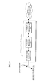
- Fig.10 depicts an arrangement of a wireless base station in a mobile communication system as a related art.
- This wireless base (BS) station 10 is schematically composed of a transmitting/receiving portion 100 connected to an antenna ANT, a baseband signal processor 200 performing a baseband signal processing to a signal transmitted/received or transferred between a mobile station (MS) 20 and the wireless base station 10, and a communication network interface (IF) 300 serving as an interface with a mobile communication network NW.
- a transmitting/receiving portion 100 connected to an antenna ANT
- a baseband signal processor 200 performing a baseband signal processing to a signal transmitted/received or transferred between a mobile station (MS) 20 and the wireless base station 10
- IF communication network interface
- the wireless base station 10 has a frequency shift (variation) arisen in an uplink signal received from the mobile station 20.
- the baseband signal processor 200 within the wireless base station 10 is provided with an AFC (Automatic Frequency Control) function for automatically controlling the frequency of an uplink signal received in accordance with a specified allocation frequency (see e.g. Japanese Laid-open Patent Publication No. 2005-295282 ).
- AFC Automatic Frequency Control
- the wireless base station provided in such a place that a mobile station moves at a high speed is desired to have a high AFC capability of dealing with a large frequency variation, which causes a problem that the circuit scale within the wireless base station is to be increased.
- F D "2.10GHz”
- F D an allocated frequency
- a reception frequency (hereinafter, mobile station reception frequency) RF 20 of the downlink signal DS in the mobile station 20 assumes a value given by the following Eq. (1): MS reception freq .
- RF 20 downlink allocate freq .
- the mobile station 20 transfers the downlink Doppler shift frequency D D to the uplink signal US without changes.
- the reception frequency (hereinafter, occasionally BS reception frequency) RF 10 of the uplink signal US in the wireless base station 10 is then to assume a value given by the following Eq.(4) under the influence of the uplink Doppler shift frequency Du (451Hz): BS reception freq .
- RF 10 MS transmission freq . TF + uplink Doppler shift freq .
- both of the downlink Doppler shift frequency D D and the uplink Doppler shift frequency Du appear as a frequency variation.
- the BS direction component of the speed V assumes "0", so that no Doppler shift is caused in the downlink signal DS and the uplink signal US, whereby the BS reception frequency RF 10 and the MS reception frequency RF 20 become equal to the uplink allocated frequency F U and the downlink allocated frequency F D , respectively.
- the BS reception frequency variation characteristic CR 10 and the MS reception frequency variation characteristic CR 20 present negative characteristics further decreasing from "0Hz" as depicted in Fig.12 . Namely, when the mobile station 20 moves away from the wireless base station 10, a negative Doppler shift is caused in both of the uplink and downlink directions.
- the wireless base station 10 when being set under the condition depicted in Figs.11A-11C , the wireless base station 10 is desired to have a very high AFC capability of dealing with a frequency variation range of "— 946Hz" to "+946Hz". Also, as the moving speed V of the mobile station 20 is increased, the influence of the Doppler shift is increased, so that the wireless base station 10 is desired to have an AFC capability of dealing therewith.
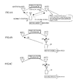
- Figs.13A-13C If the AFC capability of the wireless base station 10 is low, a problem depicted in Figs.13A-13C will arise, where it is supposed that the wireless base station 10 manage two sectors SCT1 and SCT2 as depicted in Fig.13A and the mobile station 20 perform a transmission/reception of the downlink signal DS and the uplink signal US with the sector SCT1.
- the sector switchover request REQ is not normally processed or received, so that when the mobile station 20 moves further away from the sector SCT1 as depicted in Fig.13C , the mobile station 20 may not perform a transmission/reception in any of the sectors SCT1 and SCT2, causing a communication disconnection.
- a wireless base station includes: a plurality of antennas; and a signal processor to take in reception signals from a mobile station to perform a signal transmission and reception with the mobile station by a first antenna providing a higher reception signal level, in which the signal processor switches over the signal transmission to the mobile station by the first antenna to that by a second antenna when a frequency variation characteristic measured for an allocated frequency of the reception signal from the first antenna indicates that the mobile station is moving away from the first antenna.
- the signal processor starts to perform a transmission/reception by using a first antenna of which reception level of an uplink signal from a mobile station (i.e. an antenna closer to the mobile station) is high.
- the signal processor switches over the transmission of the downlink signal to the mobile station by the first antenna to that by a second antenna.
- the mobile station moving toward the second antenna, so that a positive Doppler shift arises in the downlink signal.
- a negative Doppler shift arises in the uplink signal.
- the positive Doppler shift and the negative Doppler shift cancel with each other, presenting a suppressed frequency variation range.
- the above signal processor may determine that the mobile station is moving away from the first antenna when the frequency variation characteristic presents a negative characteristic and a variation range of the frequency variation characteristic exceeds a specified value.
- the signal processor may determine that the mobile station has moved within a fixed distance area of the second antenna, thereby switching over the signal reception from the mobile station by the first antenna to that by the second antenna as well.
- switchover is performed so that the reception of the uplink signal may be also performed by the second antenna to reduce the frequency variation generated in the uplink signal.
- the antennas and the signal processor may be provided for each sector managed by the wireless base station, in which the adjacent antennas on adjacent sectors are set close to each other to present equivalent frequency variation characteristics.
- a wireless base station system includes a plurality of slave base stations; and a master base station to take in reception signals of the slave base stations from a mobile station to select a first slave base station providing a higher reception signal level to perform a signal transmission and reception with the mobile station, in which the master base station selects a second slave base station to perform a signal transmission to the mobile station when a frequency variation characteristic measured for an allocated frequency of the reception signal for the first slave base station indicates that the mobile station is moving away from the first slave base station.
- the master base station can process the uplink signal from the mobile station without requiring a high AFC capability as with the above [1].
- a wireless base station system includes a plurality of wireless base stations, each of which further includes: a plurality of antennas; and a signal processor to take in reception signals from a mobile station to perform a signal transmission and reception with the mobile station by a first antenna providing a higher reception signal level, in which the signal processor switches over the signal transmission to the mobile station by the first antenna to that by a second antenna when a frequency variation characteristic measured for an allocated frequency of the reception signal from the first antenna indicates that the mobile station is moving away from the first antenna; and after the signal transmission to the mobile station by the first antenna has been switched over to that by the second antenna, when a variation range of the frequency variation characteristic measured with the second antenna falls below a specified value, the signal processor determines that the mobile station has moved within a fixed distance area of the second antenna, thereby switching over the signal reception from the mobile station by the first antenna to that by the second antenna as well; the adjacent antennas on adjacent wireless base stations being set close to each other to present equivalent frequency variation characteristics.
- a control method of a wireless base station having a plurality of antennas includes: taking in reception signals from a mobile station to perform a signal transmission and reception with the mobile station by a first antenna providing a higher reception signal level; measuring, during the signal transmission and reception, a frequency variation characteristic for an allocated frequency of the reception signal from the first antenna; and switching over the signal transmission to the mobile station by the first antenna to that by a second antenna when the frequency variation characteristic indicates that the mobile station is moving away from the first antenna.
- the present invention can, in any state, process an uplink signal from a mobile station without requiring a high AFC capability and can achieve an improvement of communication quality and a miniaturization of a wireless base station (circuit). Also, the present invention suppresses a frequency variation by canceling uplink and downlink Doppler shifts to a low level, so that no design change or the like is required even though the moving speed of a mobile station or a signal allocated frequency is changed. Best mode for implementing the invention
- Embodiments [1] and [2] of a wireless base station and a control method thereof according to the present invention will be hereinafter described referring to Figs.1-9 .
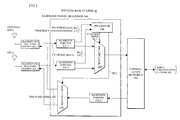
- a wireless base station 10 according to this embodiment depicted in Fig.1 is provided with two antennas ANT1 and ANT2, different from the related art arrangement depicted in Fig.10 , in which transmitting/receiving portions 100_1 and 100_2 are provided corresponding to the antennas ANT1 and ANT2.
- a baseband signal processor 200 is formed of baseband portions 210-1 and 210-2 for executing baseband signal processing which respectively convert high frequency uplink signals US outputted from the transmitting/receiving portions 100_1 and 100_2 into baseband signals and measure reception levels RL1 and RL2 (hereinafter, occasionally represented by reference numeral RL) as well as frequency variation ranges ⁇ F1 and ⁇ F2 (hereinafter, occasionally represented by reference numeral ⁇ F) of the uplink signals US; a baseband portion 210_3 for executing a baseband signal processing which converts a downlink signal DS received from a mobile communication network NW through a communication network interface (IF) 300 into a baseband signal; a multiplexer 220 which selects either one of the uplink signals US outputted from the baseband portions 210_1 and 210_2 in accordance with a selection signal SL1; a demultiplexer 230 which provides a downlink signal DS outputted from the baseband portion 210_3 to either one of the transmit
- wireless base station 10 in Fig.1 is arranged to use two antennas, an arrangement using a plurality of antennas can be similarly applied, where the above mentioned first antenna is single and the second antenna (adjacent base station) is selected among from the other antennas.
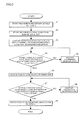
- the baseband portions 210_1 and 210_2 within the baseband signal processor 200 start to measure the reception levels RL1 and RL2 of the uplink signals US received from the antennas ANT1 and ANT2 through the transmitting/receiving portions 100_1 and 100_2 (step S1).
- the baseband portions 210_1 and 210_2 start to measure the frequency variation ranges ⁇ F1 and ⁇ F2 of the uplink signals US (step S2).
- the processor 240 having received the reception levels RL1 and RL2 respectively measured by the baseband portions 210_1 and 210_2 compares the reception levels RL1 and RL2 and provides as an output the selection signal SL1 for instructing the selection of the uplink signal US outputted from the baseband portion of which reception level is higher (i.e. uplink signal US received from the antenna of which reception level is higher) to the multiplexer 220.
- the processor 240 provides the selection signal SL2 for instructing to provide the downlink signal DS outputted from the baseband portion 210_3 to the transmitting/receiving portion 100_1 or 100_2 having the antenna of which reception level is higher to the demultiplexer 230 (step S3).
- the transmission of the downlink signal DS and the reception of the uplink signal US are to be made by the antenna ANT1, while the reception itself of the uplink signal US by the antenna ANT2 is not stopped and the frequency variation range ⁇ F2 is continuously measured.
- the moving speed V of the mobile station 20 is low and the downlink Doppler shift frequency arising in the downlink signal DS and the uplink Doppler shift frequency arising in the uplink signal US are both low, so that as depicted by a characteristic CR 10 _L of dotted lines in Fig.4 , the frequency variation of the base station reception frequency is in a small state (section B).
- the frequency variation range ⁇ F presents a large characteristic CR 10 _H of a solid line in comparison with the characteristic CR 10 _L at the low speed in the same manner as the characteristic depicted in Fig.12 .
- the processor 240 monitors whether or not the frequency variation range ⁇ F1 of the uplink signal US received from the antenna ANT1 selected has transitioned from "section B" to "section C" depicted in Fig.4 (step S4).
- the processor 240 executes no signal processing, thereby maintaining the transmission reception state by the antenna ANT1 (step S5).
- the frequency variation range ⁇ F1 of the antenna ANT1 transitions to "section C"
- the processor 240 provides the selection signal SL2 instructing to provide the downlink signal DS to the antenna ANT2 (transmitting/receiving portion 100_2), not the antenna ANT1 (transmitting/receiving portion 100_1) to the demultiplexer 230 (step S6).
- the wireless base station 10 transmit the downlink signal DS to the mobile station 20 through the antenna ANT2 and receive the uplink signal US from the mobile station 20 through the antenna ANT1.
- the reception frequency RF 20 of the mobile station 20 has the same value as the above Eq.(1).
- the uplink signal US is transmitted from the mobile station 20 at the transmission frequency TF added with the downlink Doppler shift frequency D D (495Hz), where the mobile station 20 moves away from the antenna ANT1, so that the reception frequency RF 10 of the wireless base station 10 assumes to be a value given by the following Eq.(7) under the influence of a negative Doppler shift: BS reception freq .
- RF 10 MS transmission freq . TF - uplink Doppler shift freq .
- the downlink Doppler shift frequency DD and the uplink Doppler shift frequency DU cancel with each other as expressed by the above Eq.(7), in which the frequency variation of the uplink signal US received by the wireless base station 10 is suppressed small.
- the processor 240 monitors whether or not the frequency variation range ⁇ F2 of the antenna ANT2 has transitioned from "section A” to "section B" (step S7).
- the downlink signal DS transmitted from the antenna ANT2 is influenced by a positive Doppler shift and the uplink signal US transmitted from the mobile station 20 is also influenced by the positive Doppler shift, so that the frequency variation range ⁇ F2 resides in "section A".
- the processor 240 executes no signal processing, where the transmission by the antenna ANT2 and the reception by the antenna ANT1 are maintained (step S8).
- the influence of the downlink Doppler shift is small and so weakens the cancellation with the uplink Doppler shift arising in the uplink signal US (the maximum point of the cancellation effect is a middle point between the antennas ANT1 and ANT2), so that the processor 240 provides to the multiplexer 220 the selection signal SL1 instructing to select the uplink signal US received from the antenna ANT2 (baseband portion 210_2), not from the antenna ANT1 (baseband portion 210_1) (step S9).
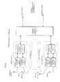
- a wireless base station system 1000 depicted in Fig.7 is formed of a slave base station (antenna device) 30_1 having the antenna ANT1 and the transmitting/receiving portion 100_1 depicted in Fig.1 , a slave base station 30_2 having the antenna ANT2 and the transmitting/receiving portion 100_2, and a master base station 40 having the baseband signal processor 200 and a communication network interface 300.
- the transmitting/receiving portion 100_1 within the slave base station 30_1 and the baseband signal processor 200 within the master base station 40 are mutually connected to transmit the downlink signal DS and receive the uplink signal US through transmission interfaces 400_11 and 400_12 mutually connected with an optical fiber FB.
- the transmitting/receiving portion 100_2 within the slave base station 30_2 and the baseband signal processor 200 within the master base station 40 are mutually connected to transmit/receive a signal through a transmission interface 400_21, the optical fiber FB and a transmission interface 400_22.
- a wireless base station 10a according to this embodiment depicted in Fig.8 is a base station managing "n" number of sectors SCT1-SCTn, each of which is equipped with antennas, transmitting/receiving portions and a baseband signal processor in the same manner as the above embodiment [1].
- adjacent antennas on adjacent sectors are set close to each other like the antennas ANT21 and ANT12 depicted so that the frequency variations of the uplink signals received may be equivalent.
- the baseband signal processor 200_1 provided corresponding to the sector SCT1 controls to perform the transmission/reception with the mobile station 20 by the antenna ANT21 in the same manner as the above embodiment [1], whereby the reception frequency variation range of the antenna ANT21 belongs to "section B" depicted in Fig.4 .
- the reception frequency variation range of the antenna ANT21 now belongs to "section B", the sector switchover request REQ is normally processed (received) and as depicted in Fig.9B the measurements of the reception level and the frequency variation range described in the above embodiment [1] with respect to the antennas ANT12 and ANT22 within the sector SCT2 are to be performed.
- the moving speed V of the mobile station 20 is "high speed", where the reception frequency variation range of the antenna ANT12 belongs to “section B" in the same manner as the antenna ANT21 within the sector SCT1, so that the communication will begin from a state where the frequency variation of the uplink signal US in the sector SCT2 is small.
- a wireless base station system equipped with a plurality of the wireless base stations 10 depicted in Fig.1 and with the adjacent antennas on adjacent base stations set close to each other can also achieve the above operation for switchover between base stations.
Applications Claiming Priority (1)
| Application Number | Priority Date | Filing Date | Title |
|---|---|---|---|
| PCT/JP2007/067667 WO2009034614A1 (fr) | 2007-09-11 | 2007-09-11 | Station de base sans fil et son procédé de commande |
Publications (2)
| Publication Number | Publication Date |
|---|---|
| EP2192814A1 true EP2192814A1 (fr) | 2010-06-02 |
| EP2192814A4 EP2192814A4 (fr) | 2014-03-19 |
Family
ID=40451639
Family Applications (1)
| Application Number | Title | Priority Date | Filing Date |
|---|---|---|---|
| EP07807076.0A Withdrawn EP2192814A4 (fr) | 2007-09-11 | 2007-09-11 | Station de base sans fil et son procédé de commande |
Country Status (4)
| Country | Link |
|---|---|
| US (1) | US8224385B2 (fr) |
| EP (1) | EP2192814A4 (fr) |
| JP (1) | JP4894926B2 (fr) |
| WO (1) | WO2009034614A1 (fr) |
Cited By (1)
| Publication number | Priority date | Publication date | Assignee | Title |
|---|---|---|---|---|
| CN103179588A (zh) * | 2011-12-20 | 2013-06-26 | 中兴通讯股份有限公司 | 无线接入点的数据处理装置及方法 |
Families Citing this family (3)
| Publication number | Priority date | Publication date | Assignee | Title |
|---|---|---|---|---|
| CN102547778B (zh) * | 2012-01-06 | 2014-12-10 | 京信通信系统(中国)有限公司 | 一种扁平化网络架构的无线通信系统、方法及扩展装置 |
| JP2014030184A (ja) * | 2012-07-06 | 2014-02-13 | Panasonic Corp | 通信装置及び無線通信システム |
| US9473228B2 (en) | 2014-01-31 | 2016-10-18 | Qualcomm Incorporated | Variable diversity RX bandwidth for self-organizing networks |
Citations (1)
| Publication number | Priority date | Publication date | Assignee | Title |
|---|---|---|---|---|
| EP1764968A2 (fr) * | 2005-09-15 | 2007-03-21 | Fujitsu Ltd. | Emetteur/Récepteur avec précompensation de dérives Doppler |
Family Cites Families (46)
| Publication number | Priority date | Publication date | Assignee | Title |
|---|---|---|---|---|
| JPS6282732A (ja) * | 1985-10-07 | 1987-04-16 | Nippon Telegr & Teleph Corp <Ntt> | 移動通信方式 |
| US5504936A (en) * | 1991-04-02 | 1996-04-02 | Airtouch Communications Of California | Microcells for digital cellular telephone systems |
| JP2876517B2 (ja) * | 1994-02-16 | 1999-03-31 | 松下電器産業株式会社 | Cdma/tdd方式基地局装置およびcdma/tdd方式移動局装置およびcdma/tdd方式無線通信システムおよびcdma/tdd方式無線通信方法 |
| JPH0884104A (ja) * | 1994-09-09 | 1996-03-26 | Toshiba Corp | 無線通信装置 |
| MY120873A (en) * | 1994-09-30 | 2005-12-30 | Qualcomm Inc | Multipath search processor for a spread spectrum multiple access communication system |
| US5732351A (en) * | 1995-08-31 | 1998-03-24 | Motorola, Inc. | Communication system and method for single channel hand-offs |
| US5669060A (en) * | 1996-03-04 | 1997-09-16 | Telefonaktiebolaget L M Ericsson (Publ) | Method and apparatus for enhancing call set-up and handoff quality |
| FI107851B (fi) * | 1996-05-22 | 2001-10-15 | Nokia Networks Oy | Menetelmä antennikeilan valitsemiseksi, tukiasema ja solukkoradiojärjestelmä |
| US5890067A (en) * | 1996-06-26 | 1999-03-30 | Bnr Inc. | Multi-beam antenna arrays for base stations in which the channel follows the mobile unit |
| CN1113488C (zh) * | 1996-11-26 | 2003-07-02 | 三洋电机株式会社 | 移动通信系统的基站 |
| US6052605A (en) * | 1997-03-31 | 2000-04-18 | Radio Frequency Systems, Inc. | Continuous interference assessment and avoidance in a land mobile radio system |
| JPH118577A (ja) * | 1997-06-17 | 1999-01-12 | Saitama Nippon Denki Kk | 無線機 |
| US6594475B1 (en) * | 1999-09-09 | 2003-07-15 | International Business Machines Corporation | Mobile battery discharge minimization in indoor wireless networks by antenna switching |
| JP4318389B2 (ja) * | 2000-04-03 | 2009-08-19 | 三洋電機株式会社 | アダプティブアレー装置、無線基地局、携帯電話機 |
| JP2001320756A (ja) * | 2000-05-11 | 2001-11-16 | Nec Saitama Ltd | 上り回線過負荷検出回路と基地局装置 |
| US7155229B2 (en) * | 2002-01-08 | 2006-12-26 | Ericsson Inc. | Distributed wireless architecture using microcast |
| KR100547882B1 (ko) * | 2002-02-26 | 2006-02-01 | 삼성전자주식회사 | 안테나 선택 다이버시티를 지원하는 이동통신시스템에서순방향 채널 상태 정보를 송수신하는 방법 및 장치 |
| JP2003283411A (ja) * | 2002-03-22 | 2003-10-03 | Sanyo Electric Co Ltd | 無線装置、送受信指向性制御方法および送受信指向性制御プログラム |
| JP2004015518A (ja) * | 2002-06-07 | 2004-01-15 | Hitachi Kokusai Electric Inc | 移動無線システムの無線チャネル接続切替方式 |
| JP3877158B2 (ja) * | 2002-10-31 | 2007-02-07 | ソニー・エリクソン・モバイルコミュニケーションズ株式会社 | 周波数偏移検出回路及び周波数偏移検出方法、携帯通信端末 |
| US7953372B2 (en) * | 2003-04-07 | 2011-05-31 | Yoram Ofek | Directional antenna sectoring system and methodology |
| JP4193589B2 (ja) * | 2003-05-28 | 2008-12-10 | 日本電気株式会社 | 携帯通信端末及びそのアンテナ切替方法 |
| JP2005295282A (ja) | 2004-03-31 | 2005-10-20 | Kyocera Corp | 通信装置及び周波数偏移低減方法 |
| KR100651447B1 (ko) * | 2004-04-14 | 2006-11-29 | 삼성전자주식회사 | 복수의 안테나들을 사용하는 셀룰러 이동통신 시스템에서의 안테나 재 선택 시스템 및 방법 |
| JP2005341531A (ja) * | 2004-04-27 | 2005-12-08 | Matsushita Electric Ind Co Ltd | 無線通信システム及び無線局 |
| US8019352B2 (en) * | 2004-07-23 | 2011-09-13 | Wireless Valley Communications, Inc. | System, method, and apparatus for determining and using the position of wireless devices or infrastructure for wireless network enhancements |
| JP4566671B2 (ja) * | 2004-09-27 | 2010-10-20 | 京セラ株式会社 | 移動通信端末および移動通信端末のデータ受信方法 |
| US7457347B2 (en) * | 2004-11-08 | 2008-11-25 | Interdigital Technology Corporation | Method and apparatus for estimating and correcting baseband frequency error in a receiver |
| US7359362B2 (en) * | 2005-01-28 | 2008-04-15 | Microsoft Corporation | Control of a multi-sectored antenna system to improve channel efficiency |
| JP4463304B2 (ja) * | 2005-05-20 | 2010-05-19 | 富士通株式会社 | 無線通信装置、移動端末装置及び無線通信方法 |
| US8219042B2 (en) | 2005-09-26 | 2012-07-10 | Sharp Kabushiki Kaisha | Wireless communication system, base station device, mobile station device, and macrodiversity selection method |
| KR100678092B1 (ko) * | 2006-02-09 | 2007-02-02 | 삼성전자주식회사 | 다중 입력 다중 출력 방식을 이용한 광대역 분산 네트워크시스템 |
| KR100678096B1 (ko) * | 2006-02-14 | 2007-02-02 | 삼성전자주식회사 | 다중 입력 다중 출력 방식을 이용한 광대역 분산 네트워크시스템의 핸드오프 제어방법 |
| JP4541414B2 (ja) * | 2006-04-28 | 2010-09-08 | 富士通株式会社 | 受信ダイバシチ機能を有するw−cdma方式による移動機、及びそのシステム |
| JP4788905B2 (ja) * | 2006-05-01 | 2011-10-05 | 日本電気株式会社 | 移動通信システム及び基地局アンテナ近接状況判断方法 |
| US7925230B2 (en) * | 2006-08-25 | 2011-04-12 | Infineon Technologies Ag | Diversity receiver with channel estimator |
| US20080132173A1 (en) * | 2006-11-30 | 2008-06-05 | Korea Advanced Institute Of Science And Technology | Channel estimation apparatus and channel estimation method |
| EP2624474A3 (fr) * | 2006-12-14 | 2013-09-18 | Fujitsu Limited | Unité de commande de sélection d'antenne pour communication MIMO |
| US7885619B2 (en) * | 2007-06-12 | 2011-02-08 | Telefonaktiebolaget Lm Ericsson (Publ) | Diversity transmission using a single power amplifier |
| US9112547B2 (en) * | 2007-08-31 | 2015-08-18 | Adc Telecommunications, Inc. | System for and method of configuring distributed antenna communications system |
| JP4539891B2 (ja) * | 2008-08-11 | 2010-09-08 | 岩崎通信機株式会社 | マルチアンテナを用いた無線通信方法、無線通信システムおよび無線通信装置 |
| WO2010023890A1 (fr) * | 2008-08-28 | 2010-03-04 | パナソニック株式会社 | Dispositif de transmission sans fil, procédé de transmission sans fil, programme et circuit intégré |
| US8838116B2 (en) * | 2009-05-19 | 2014-09-16 | Qualcomm Incorporated | Minimizing interference to non-associated users |
| IT1395644B1 (it) * | 2009-05-27 | 2012-10-16 | Bitmanufaktur Gmbh | Dispositivo hardware wireless per il rilevamento di relazioni di distanza, e sistema di monitoraggio di relazioni di distanza tra dispositivi hardware wireless |
| US8351944B2 (en) * | 2009-06-16 | 2013-01-08 | Verizon Patent And Licensing Inc. | Soft handover for mobile device |
| US10110288B2 (en) * | 2009-11-04 | 2018-10-23 | Atc Technologies, Llc | Frequency division duplex (FDD) return link transmit diversity systems, methods and devices using forward link side information |
-
2007
- 2007-09-11 JP JP2009531996A patent/JP4894926B2/ja not_active Expired - Fee Related
- 2007-09-11 WO PCT/JP2007/067667 patent/WO2009034614A1/fr active Application Filing
- 2007-09-11 EP EP07807076.0A patent/EP2192814A4/fr not_active Withdrawn
-
2010
- 2010-03-05 US US12/718,502 patent/US8224385B2/en not_active Expired - Fee Related
Patent Citations (1)
| Publication number | Priority date | Publication date | Assignee | Title |
|---|---|---|---|---|
| EP1764968A2 (fr) * | 2005-09-15 | 2007-03-21 | Fujitsu Ltd. | Emetteur/Récepteur avec précompensation de dérives Doppler |
Non-Patent Citations (1)
| Title |
|---|
| See also references of WO2009034614A1 * |
Cited By (3)
| Publication number | Priority date | Publication date | Assignee | Title |
|---|---|---|---|---|
| CN103179588A (zh) * | 2011-12-20 | 2013-06-26 | 中兴通讯股份有限公司 | 无线接入点的数据处理装置及方法 |
| WO2013091347A1 (fr) * | 2011-12-20 | 2013-06-27 | 中兴通讯股份有限公司 | Dispositif et procédé de traitement de données pour un point d'accès sans fil |
| CN103179588B (zh) * | 2011-12-20 | 2018-08-03 | 南京中兴新软件有限责任公司 | 无线接入点的数据处理装置及方法 |
Also Published As
| Publication number | Publication date |
|---|---|
| EP2192814A4 (fr) | 2014-03-19 |
| JP4894926B2 (ja) | 2012-03-14 |
| US20100157949A1 (en) | 2010-06-24 |
| JPWO2009034614A1 (ja) | 2010-12-16 |
| WO2009034614A1 (fr) | 2009-03-19 |
| US8224385B2 (en) | 2012-07-17 |
Similar Documents
| Publication | Publication Date | Title |
|---|---|---|
| JP4453168B2 (ja) | 移動通信制御方法、セルラシステム、移動局、基地局及び基地局制御装置 | |
| EP2273813B1 (fr) | Station de radio, station de transmission et procédé de partage de bande de fréquence | |
| EP1128573A2 (fr) | Procédé pour éviter interférences dues aux fréquences porteuses adjacentes | |
| KR101096497B1 (ko) | Cdma 언더레이 시스템과 오버레이 시스템들 사이의경계에서의 핸드오프 방법 | |
| US20180069596A1 (en) | Tdd repeater for a wireless network and method for operating said repeater | |
| KR101103185B1 (ko) | 무선통신 시스템, 이동국, 기지국, 무선통신 방법 | |
| EP1843612B1 (fr) | Appareil de mesure et procédé de mesure de la qualité d'une zone | |
| JP4993120B2 (ja) | 上りリンク無線伝送における複数基地局と移動局の同期システム及び方法 | |
| US20060286983A1 (en) | Code-division-multiple-access mobile communication system accommodating increased number of mobile stations | |
| WO2003056712A1 (fr) | Procede de transfert entre systemes | |
| EP2192814A1 (fr) | Station de base sans fil et son procédé de commande | |
| EP1912463A2 (fr) | Système de communication mobile et procédé de contrôle de transfert | |
| JP4127686B2 (ja) | 無線通信システム、広域無線基地局装置、狭域無線基地局装置 | |
| KR100959333B1 (ko) | 무선통신 시스템에서 보조대역을 이용한 양방향 통신 장치 | |
| JP2006093895A (ja) | 基地局及び移動体通信方法 | |
| JPH11122654A (ja) | 符号分割多重セルラー移動無線通信システム、基地局選択方法、及び移動局装置 | |
| RU2520975C2 (ru) | Способ и устройство для ретрансляции радиочастотной связи между устройствами связи, расположенными в различных средах | |
| KR100800861B1 (ko) | 통신 시스템에서 핸드오프 장치 및 방법 | |
| KR101300986B1 (ko) | 이동통신 시스템에서 서빙 섹터 선택 장치 및 방법 | |
| KR102137253B1 (ko) | 기준 신호의 초기 타이밍 설정 방법 및 그 장치 | |
| JPS63245025A (ja) | 移動無線チヤネル制御方式 | |
| KR20010008722A (ko) | 이동통신 시스템에서 위치정보를 이용한 핸드오프 방법 | |
| JP3913557B2 (ja) | 無線基地装置、伝送チャネル割当方法および伝送チャネル割当プログラム | |
| EP0783802B1 (fr) | Procede et dispositif permettant une commande d'acces en fonction de l'evanouissement dans un systeme a faisceau hertzien numerique | |
| KR20060022962A (ko) | 지하철 무선 랜 시스템의 무선 전파 간섭 방지 방법 |
Legal Events
| Date | Code | Title | Description |
|---|---|---|---|
| PUAI | Public reference made under article 153(3) epc to a published international application that has entered the european phase |
Free format text: ORIGINAL CODE: 0009012 |
|
| 17P | Request for examination filed |
Effective date: 20100408 |
|
| AK | Designated contracting states |
Kind code of ref document: A1 Designated state(s): AT BE BG CH CY CZ DE DK EE ES FI FR GB GR HU IE IS IT LI LT LU LV MC MT NL PL PT RO SE SI SK TR |
|
| AX | Request for extension of the european patent |
Extension state: AL BA HR MK RS |
|
| DAX | Request for extension of the european patent (deleted) | ||
| A4 | Supplementary search report drawn up and despatched |
Effective date: 20140113 |
|
| RIC1 | Information provided on ipc code assigned before grant |
Ipc: H01Q 1/24 20060101ALI20140107BHEP Ipc: H04B 7/08 20060101ALI20140107BHEP Ipc: H04W 84/00 20090101AFI20140107BHEP Ipc: H04W 64/00 20090101ALI20140107BHEP Ipc: H04W 88/08 20090101ALI20140107BHEP Ipc: H04W 16/24 20090101ALI20140107BHEP Ipc: H04W 24/10 20090101ALI20140107BHEP Ipc: H04B 7/06 20060101ALI20140107BHEP |
|
| 17Q | First examination report despatched |
Effective date: 20140205 |
|
| RA4 | Supplementary search report drawn up and despatched (corrected) |
Effective date: 20140218 |
|
| GRAP | Despatch of communication of intention to grant a patent |
Free format text: ORIGINAL CODE: EPIDOSNIGR1 |
|
| INTG | Intention to grant announced |
Effective date: 20171004 |
|
| RIN1 | Information on inventor provided before grant (corrected) |
Inventor name: KANDA, TAKASHI |
|
| STAA | Information on the status of an ep patent application or granted ep patent |
Free format text: STATUS: THE APPLICATION IS DEEMED TO BE WITHDRAWN |
|
| 18D | Application deemed to be withdrawn |
Effective date: 20180215 |