EP2191945B1 - Vorrichtung zum Durchtrennen des Klebewulstes von eingeklebten Scheiben - Google Patents
Vorrichtung zum Durchtrennen des Klebewulstes von eingeklebten Scheiben Download PDFInfo
- Publication number
- EP2191945B1 EP2191945B1 EP09177355.6A EP09177355A EP2191945B1 EP 2191945 B1 EP2191945 B1 EP 2191945B1 EP 09177355 A EP09177355 A EP 09177355A EP 2191945 B1 EP2191945 B1 EP 2191945B1
- Authority
- EP
- European Patent Office
- Prior art keywords
- cutting means
- winding
- drive
- cutting
- winding device
- Prior art date
- Legal status (The legal status is an assumption and is not a legal conclusion. Google has not performed a legal analysis and makes no representation as to the accuracy of the status listed.)
- Not-in-force
Links
- 239000000853 adhesive Substances 0.000 title claims description 28
- 230000001070 adhesive effect Effects 0.000 title claims description 28
- 238000005520 cutting process Methods 0.000 claims description 70
- 238000004804 winding Methods 0.000 claims description 48
- 239000011324 bead Substances 0.000 claims description 22
- 230000011664 signaling Effects 0.000 claims description 5
- 230000004913 activation Effects 0.000 claims description 3
- 238000000034 method Methods 0.000 description 4
- 230000003287 optical effect Effects 0.000 description 3
- 230000008569 process Effects 0.000 description 3
- 230000009467 reduction Effects 0.000 description 3
- 230000009471 action Effects 0.000 description 2
- 238000010276 construction Methods 0.000 description 2
- 230000008878 coupling Effects 0.000 description 2
- 238000010168 coupling process Methods 0.000 description 2
- 238000005859 coupling reaction Methods 0.000 description 2
- 239000000463 material Substances 0.000 description 2
- 239000004033 plastic Substances 0.000 description 2
- 229920003023 plastic Polymers 0.000 description 2
- 229920002635 polyurethane Polymers 0.000 description 2
- 239000004814 polyurethane Substances 0.000 description 2
- 230000004044 response Effects 0.000 description 2
- 230000003213 activating effect Effects 0.000 description 1
- 238000013459 approach Methods 0.000 description 1
- 238000005452 bending Methods 0.000 description 1
- 230000005540 biological transmission Effects 0.000 description 1
- 239000003795 chemical substances by application Substances 0.000 description 1
- 239000011248 coating agent Substances 0.000 description 1
- 238000000576 coating method Methods 0.000 description 1
- 238000007511 glassblowing Methods 0.000 description 1
- 230000007246 mechanism Effects 0.000 description 1
- 238000000926 separation method Methods 0.000 description 1
- 239000004575 stone Substances 0.000 description 1
Images

Classifications
-
- B—PERFORMING OPERATIONS; TRANSPORTING
- B26—HAND CUTTING TOOLS; CUTTING; SEVERING
- B26B—HAND-HELD CUTTING TOOLS NOT OTHERWISE PROVIDED FOR
- B26B7/00—Hand knives with reciprocating motor-driven blades
-
- B—PERFORMING OPERATIONS; TRANSPORTING
- B26—HAND CUTTING TOOLS; CUTTING; SEVERING
- B26B—HAND-HELD CUTTING TOOLS NOT OTHERWISE PROVIDED FOR
- B26B27/00—Hand cutting tools not provided for in the preceding groups, e.g. finger rings for cutting string, devices for cutting by means of wires
- B26B27/002—Tools using wires as cutting means
-
- B—PERFORMING OPERATIONS; TRANSPORTING
- B26—HAND CUTTING TOOLS; CUTTING; SEVERING
- B26D—CUTTING; DETAILS COMMON TO MACHINES FOR PERFORATING, PUNCHING, CUTTING-OUT, STAMPING-OUT OR SEVERING
- B26D1/00—Cutting through work characterised by the nature or movement of the cutting member or particular materials not otherwise provided for; Apparatus or machines therefor; Cutting members therefor
- B26D1/01—Cutting through work characterised by the nature or movement of the cutting member or particular materials not otherwise provided for; Apparatus or machines therefor; Cutting members therefor involving a cutting member which does not travel with the work
- B26D1/547—Cutting through work characterised by the nature or movement of the cutting member or particular materials not otherwise provided for; Apparatus or machines therefor; Cutting members therefor involving a cutting member which does not travel with the work having a wire-like cutting member
-
- Y—GENERAL TAGGING OF NEW TECHNOLOGICAL DEVELOPMENTS; GENERAL TAGGING OF CROSS-SECTIONAL TECHNOLOGIES SPANNING OVER SEVERAL SECTIONS OF THE IPC; TECHNICAL SUBJECTS COVERED BY FORMER USPC CROSS-REFERENCE ART COLLECTIONS [XRACs] AND DIGESTS
- Y10—TECHNICAL SUBJECTS COVERED BY FORMER USPC
- Y10T—TECHNICAL SUBJECTS COVERED BY FORMER US CLASSIFICATION
- Y10T156/00—Adhesive bonding and miscellaneous chemical manufacture
- Y10T156/11—Methods of delaminating, per se; i.e., separating at bonding face
- Y10T156/1168—Gripping and pulling work apart during delaminating
- Y10T156/1179—Gripping and pulling work apart during delaminating with poking during delaminating [e.g., jabbing, etc.]
- Y10T156/1184—Piercing layer during delaminating [e.g., cutting, etc.]
-
- Y—GENERAL TAGGING OF NEW TECHNOLOGICAL DEVELOPMENTS; GENERAL TAGGING OF CROSS-SECTIONAL TECHNOLOGIES SPANNING OVER SEVERAL SECTIONS OF THE IPC; TECHNICAL SUBJECTS COVERED BY FORMER USPC CROSS-REFERENCE ART COLLECTIONS [XRACs] AND DIGESTS
- Y10—TECHNICAL SUBJECTS COVERED BY FORMER USPC
- Y10T—TECHNICAL SUBJECTS COVERED BY FORMER US CLASSIFICATION
- Y10T156/00—Adhesive bonding and miscellaneous chemical manufacture
- Y10T156/19—Delaminating means
- Y10T156/1961—Severing delaminating means [e.g., chisel, etc.]
- Y10T156/1967—Cutting delaminating means
-
- Y—GENERAL TAGGING OF NEW TECHNOLOGICAL DEVELOPMENTS; GENERAL TAGGING OF CROSS-SECTIONAL TECHNOLOGIES SPANNING OVER SEVERAL SECTIONS OF THE IPC; TECHNICAL SUBJECTS COVERED BY FORMER USPC CROSS-REFERENCE ART COLLECTIONS [XRACs] AND DIGESTS
- Y10—TECHNICAL SUBJECTS COVERED BY FORMER USPC
- Y10T—TECHNICAL SUBJECTS COVERED BY FORMER US CLASSIFICATION
- Y10T83/00—Cutting
- Y10T83/04—Processes
-
- Y—GENERAL TAGGING OF NEW TECHNOLOGICAL DEVELOPMENTS; GENERAL TAGGING OF CROSS-SECTIONAL TECHNOLOGIES SPANNING OVER SEVERAL SECTIONS OF THE IPC; TECHNICAL SUBJECTS COVERED BY FORMER USPC CROSS-REFERENCE ART COLLECTIONS [XRACs] AND DIGESTS
- Y10—TECHNICAL SUBJECTS COVERED BY FORMER USPC
- Y10T—TECHNICAL SUBJECTS COVERED BY FORMER US CLASSIFICATION
- Y10T83/00—Cutting
- Y10T83/929—Tool or tool with support
- Y10T83/9292—Wire tool
Definitions
- the invention relates to a device for severing an adhesive bead of a disc, in particular a vehicle window, with a winding device, with a coil for winding a cutting means in the working direction for severing the adhesive bead, wherein the winding device comprises a motor drive with a control with a switch for Switching on the drive is coupled.
- EP 1 834 741 A1 A device of the aforementioned type is known from EP 1 834 741 A1 known.
- the device according to the invention will be explained in more detail below with reference to an exemplary embodiment, which refers to a detachment of a windshield, it is understood that this is not to be understood as limiting and rather, the device is generally applicable to the removal of glued-in panes, eg in motor vehicles, buildings, railway trains, cable car cabins, aircraft and ships.
- the windscreens are connected by an adhesive bead of a polyurethane adhesive or other suitable adhesive firmly with a circumferential body flange.
- the adhesive bead consists of such a strong adhesive that in conjunction with the windshield, the mechanical stability of the vehicle is increased. It is understood that the separation of the adhesive due to its high strength and toughness is thus relatively complex.
- the winding device is supported by means of a support on the body flange, while the winding device is driven to cut through the adhesive bead gradually.
- the winding device is guided along with the support according to the progress of the cutting process along the body flange.
- a universal motor is used in conjunction with a reduction gear to provide the necessary traction on the cutting means and allow slow wrapping. Because of the support of the winding device on the body flange of the removal process usually has to be interrupted several times before it can be further worked after appropriate implementation of the winding device at another point. For this purpose, it is sometimes necessary to pull the cutting means against the working direction again from the winding device. As a result of in the Usually existing reduction gear this requires a considerable effort.
- a device for driving windshields is also known, in which a switchable in its direction of rotation drive motor is provided.
- the invention is based on the object to provide an improved device for severing the adhesive bead of a disc, with a possible power-saving and easy work is possible.
- the winding device has a strain relief for the cutting means, which allows withdrawal of the cutting means from the winding device against the working direction, and that the controller is designed such that the drive to is turned off for a certain period of time against the working direction.
- the coil automatically rotates counter to the working direction for a limited time. The user can thus retract the winder without much effort.
- cutting means is to be understood as meaning any wire or even any cord which is basically suitable for severing the adhesive bead of a vehicle window. This means that the cutting means must have sufficient resistance to tearing and bending and, if appropriate, be provided with a suitable coating or suitable surface features in the form of tooth approaches or the like in order to assist the cutting process. It is understood, however, that the term “cutting means” is also to be understood as a suitable cord made of plastic or another material.
- the winding device on a drive which is switchable to the strain relief of the cutting means between clockwise and counterclockwise rotation.
- the strain relief on a mechanical overrunning clutch is provided.
- the controller is designed such that the drive rewinds the cutting means back to the initial state, if after pulling off the drive no tensile force is exerted on the cutting means.
- the controller is designed such that the cutting means is unwound after a shutdown of the drive when a tensile force is exerted on the cutting means.
- the user is provided a particularly convenient way to retract the cutting means. If no tensile force is exerted on the cutting means, so also remains unwinding, so that incorrect operations are avoided and also jamming of the cutting means in the coil is reliably avoided.
- control is in this case designed such that the cutting means is unwound the faster, the greater the tensile force exerted on the cutting means.
- the unwinding is terminated when no more pulling force is exerted on the cutting means.
- a signal means is provided which signals activation of the strain relief device.
- the cutting means is again unwound from the spool, so that it can coordinate its movement with the winding device in a suitable manner. It can be about one act optical and / or acoustic signaling agent. Furthermore, the winding device can also be put into vibration, for example, in order to signal a user to this operating mode.
- the drive has, according to a further embodiment of the invention, an overload protection whose response is indicated via a signal means.
- the overload protection responds so that he can take appropriate action.
- the cutting means may be jammed between the body flange and the vehicle window or jammed in the coil.
- the signaling means may be the same signal means already mentioned above or another signaling means, so that the user can distinguish the response of the overload protection from the activation of the strain relief device. It may therefore be, for example, different acoustic and / or optical signals.
- the overload protection for example, have a mechanically releasable coupling. In this way, an overload of the drive is avoided in a simple and reliable manner.
- the winding device has a coupled to the coil drive, and further comprises a handle at a first end, wherein at a second end opposite the handle a removable support for guiding the winding device to a frame, glued to the vehicle window is, or is provided on the adhesive bead itself.
- the winding device has a housing that widens approximately wedge-shaped, starting from the support to the handle.
- This measure helps ensure that the winding device can be attached to the support on the body flange even under geometrically unfavorable conditions, since larger-volume parts of the winding device are arranged further away from the support.
- the support can be exchanged for another, more suitable, support.
- a device according to the invention is designated overall by the numeral 10.
- the device 10 comprises a winding device 24 for winding a cutting means 18, which serves for severing an adhesive bead 34 of a vehicle window 12.
- the vehicle window 12 may be, for example, a windshield of a motor vehicle, which is glued to a body flange 14 by means of the adhesive bead 34, which consists of a very tough plastic material, such as polyurethane adhesive.
- the adhesive bead 34 is extremely stable and contributes to the inherent stability of the vehicle.
- the winding device 24 has a housing 20, at one end of a handle 22 is provided. Starting from the handle 22, the housing 20 tapers according to Fig. 3 approximately wedge-shaped toward the opposite end to which a support 32 is removably attached.
- the cutting means 18 can be wound by means of an electric drive 26 on a spool 28 or unwound therefrom. To guide the cutting means 18 to the coil 28 are on the support 32, two guide rollers 50, 52 provided by the largely tangential winding of the cutting means 18 is ensured on the spool.
- the cutting means 18 is first guided completely around the adhesive bead 34 from the outside. Then we fixed a first end either from the outside to a stationary vehicle part, for example to the windshield wiper shaft or with the help of a suction cup on the vehicle window itself from the outside or from the inside, to which a previous execution by the adhesive bead 34 is required. Then, the second end of the cutting means 18 is passed through the adhesive bead 34 and attached to the winding device 24. The winding device 24 is now supported with its support 32 on the frame or body flange 14 and the drive of the winding device 26 is actuated.
- the cutting means 18 is gradually pulled through the adhesive bead 34, so that it is severed.
- the angle 42 between the cutting means 18 and the body flange 14 should be kept as small as possible, whereby a good cutting action is achieved.
- the winding device 24 is thus gradually guided along with the support 32 along the frame 14 according to the progress of the cutting process, so that the angle between the cutting means and body flange 14 is not too large, as in Fig. 1 indicated by the dashed line position of the cutting means 18 'and the angle 42'. It is also conceivable to guide the support 32 along the adhesive bead 34.
- the support 32, on which the guide rollers 50, 52 are provided, by means of a clamping device 80 removably attached to the housing 20 of the winding device 24 is fixed (see. Fig. 2 ).
- the drive 26 has a DC motor 27, which is coupled via a gear 29 with the coil 28 to the drive.
- the motor 27 is powered by an accumulator 30 with power, which is removably attached to the housing 20. It will be understood, however, that instead of this a mains powered version may be used or that any other suitable type of drive, e.g. a compressed air drive can be used.
- the cutting means 18 When driving the spool 28, the cutting means 18 is wound in the working direction via the guide rollers 50, 52 through an opening 70 on the spool 28.
- the housing 20 of the winding device 24, starting from the handle 22 tapers approximately wedge-shaped with an angle ⁇ of about 13 ° to the opposite end, to which the support 32 is attached.
- the angle ⁇ is preferably in a range of about 10 to 30 °.
- the winding device 24 is formed at its the body flange 14 during use facing the end relatively narrow, so that a support on the frame or body flange 14 even with obstacles, as they occur on dashboards, is relatively easy. It is understood that for this purpose a respective suitable support 32 can be used, which is adapted to the geometric conditions in the respective vehicle model.
- the removal process by winding the cutting means 18 on the spool 28 in the working direction must usually be interrupted several times, since the winding device 24 must be moved past obstacles on the dashboard and must be re-attached to the support 32 on the frame or body flange 14. Partial this is an intermediate withdrawal of the cutting means 18 from the coil 28 is required.
- the strain relief device 36 may comprise a mechanical one-way clutch, which is directly coupled to the transmission 29. Thereby, a withdrawal of the cutting means 18 is made possible from the coil 28 when the drive 26 is not activated.
- the winding device 24 is provided with an intelligent controller 46, which detects when the drive 26 is switched off that a force is exerted on the cutting means 18 in order to pull it out of the coil 28.
- the winding device 24 supports the user in this case by the coil 28 is driven counter to the working direction, so that the cutting means 18 is unwound from the coil 28 again.
- the arrangement is preferably now made so that the cutting means 18 is unwound the faster, the greater the tensile force exerted on the cutting means 18.
- the unwinding process is terminated as soon as the user no longer pulls on the winding device 24, or when a switch 44 for activating the drive 26 is actuated.
- the switch 44 is designed as a throttle switch and is according to Fig. 4 received directly on the handle 22.
- the accelerator switch 44 is actuated by a pusher. Via the accelerator switch 44, the user can control the desired reel speed and thus the cutting speed.
- Integrated in the drive train is also a mechanical clutch, the in Fig. 4 indicated by 49.
- the coupling 49 protects the cutting means 18 against overload and breakage.
- This overload protection 49 triggers as soon as the maximum permissible tensile force on the cutting means 18 is reached. If the overload protection 49 triggers, this is signaled to the user, for which purpose an optical and / or acoustic signal means 48 is provided. Even if the strain relief device 36 is activated to pull the cutting means against the working direction of the coil 28 to be able to, this is indicated by a corresponding signal, to which also the signal means 48 can be used. For example, different beeps may be used to activate the strain relief device 36 and to activate the overload protection 49. Alternatively, a mechanical display, for example in the form of a ratchet or a vibration can be used.
Landscapes
- Life Sciences & Earth Sciences (AREA)
- Forests & Forestry (AREA)
- Engineering & Computer Science (AREA)
- Mechanical Engineering (AREA)
- Automobile Manufacture Line, Endless Track Vehicle, Trailer (AREA)
- Replacement Of Web Rolls (AREA)
- Processing And Handling Of Plastics And Other Materials For Molding In General (AREA)
Description
- Die Erfindung betrifft eine Vorrichtung zum Durchtrennen eines Klebewulstes einer Scheibe, insbesondere einer Fahrzeugscheibe, mit einer Wickeleinrichtung, mit einer Spule zum Aufwickeln eines Schneidmittels in Arbeitsrichtung zum Durchtrennen des Klebewulstes, wobei die Wickeleinrichtung einen motorischen Antrieb umfasst, der mit einer Steuerung mit einem Schalter zum Einschalten des Antriebs gekoppelt ist.
- Eine Vorrichtung der vorstehend genannten Art ist aus der
EP 1 834 741 A1 bekannt. - Auch wenn die erfindungsgemäße Vorrichtung im Folgenden an Hand eines Ausführungsbeispiels näher erläutert wird, das auf ein Austrennen einer Windschutzscheibe Bezug nimmt, so versteht es sich, dass dies nicht einschränkend zu verstehen ist und dass die Vorrichtung vielmehr allgemein beim Austrennen von eingeklebten Scheiben verwendbar ist, z.B. in Kraftfahrzeugen, Gebäuden, Eisenbahnzügen, Seilbahnkabinen, Flugzeugen und Schiffen.
- Bei modernen Kraftfahrzeugen sind die Windschutzscheiben durch einen Klebewulst aus einem Polyurethankleber oder einem anderen geeigneten Kleber fest mit einem umlaufenden Karosserieflansch verbunden. Der Klebewulst besteht aus einem derart festen Kleber, dass in Verbindung mit der Windschutzscheibe die mechanische Stabilität des Fahrzeugs erhöht wird. Es versteht sich, dass die Durchtrennung des Klebers infolge seiner hohen Festigkeit und Zähigkeit somit relativ aufwändig ist.
- Da Windschutzscheiben infolge von Steinschlagschäden oder anderen Beschädigungen jedoch relativ häufig ausgetauscht werden müssen, ist es erforderlich, für jedes Fahrzeug eine geeignete Vorrichtung bzw. ein geeignetes Verfahren zum Ausglasen der Windschutzscheibe bereitzustellen.
- Bei der Vorrichtung gemäß der
DE 10 2006 013 417 A1 wird die Wickeleinrichtung mittels einer Stütze am Karosserieflansch abgestützt, während die Wickeleinrichtung angetrieben wird, um den Klebewulst nach und nach zu durchtrennen. Hierbei wird die Wickeleinrichtung mit der Stütze entsprechend des Fortschrittes des Schneidvorgangs am Karosserieflansch entlang geführt. - Zum Antrieb der Vorrichtung gemäß der
DE 10 2006 013 417 A1 wird in der Regel ein Universalmotor in Verbindung mit einem Untersetzungsgetriebe verwendet, um die notwendige Zugkraft auf das Schneidmittel zu gewährleisten und ein langsames Einwickeln zu ermöglichen. Wegen der Abstützung der Wickeleinrichtung am Karosserieflansch muss der Austrennvorgang in der Regel mehrfach unterbrochen werden, bevor nach entsprechender Umsetzung der Wickeleinrichtung an einer anderen Stelle weitergearbeitet werden kann. Hierzu ist es teilweise erforderlich, das Schneidmittel entgegen der Arbeitsrichtung wieder aus der Wickeleinrichtung herauszuziehen. Infolge des in der Regel vorhandenen Untersetzungsgetriebes ist hierzu ein erheblicher Kraftaufwand notwendig. - Aus der
WO 86/07017 A1 - Schließlich ist aus der
WO 2004/103748 A1 eine Vorrichtung zum Ansteuern von Fahrzeugscheiben bekannt, bei der zum Abwickeln des Drahtes ein mechanischer Entriegelungsmechanismus vorgesehen ist. - Der Erfindung liegt vor diesem Hintergrund die Aufgabe zugrunde, eine verbesserte Vorrichtung zum Durchtrennen des Klebewulstes einer Scheibe zu schaffen, mit der ein möglichst Kraft sparendes und einfaches Arbeiten ermöglicht ist.
- Diese Aufgabe wird bei einer Vorrichtung gemäß der eingangs genannten Art erfindungsgemäß dadurch gelöst, dass die Wickeleinrichtung eine Zugentlastungseinrichtung für das Schneidmittel aufweist, die ein Herausziehen des Schneidmittels aus der Wickeleinrichtung entgegen der Arbeitsrichtung erlaubt, und dass die Steuerung derart ausgebildet ist, dass der Antrieb nach einem Ausschalten für eine bestimmte Zeitspanne entgegen der Arbeitsrichtung gedreht wird.
- Die Aufgabe der Erfindung wird auf diese Weise vollkommen gelöst.
- Durch die Zugentlastungseinrichtung wird nämlich gewährleistet, dass dann, wenn der Aufwickelvorgang in Arbeitsrichtung unterbrochen ist, ein Herausziehen des Schneidmittels aus der Wickeleinrichtung entgegen der Arbeitsrichtung ermöglicht ist. Hierdurch ist ein Kraft sparendes Arbeiten ermöglicht, wenn das Schneidmittel entgegen der Arbeitsrichtung aus der Wickeleinrichtung herausgezogen werden muss.
- Bei ausgeschaltetem Antrieb dreht die Spule für eine begrenzte Zeit automatisch entgegen der Arbeitsrichtung. Der Anwender kann so die Wickeleinrichtung ohne größeren Kraftaufwand zurückziehen.
- Im Sinne dieser Anmeldung ist unter "Schneidmittel" jeglicher Draht oder auch jegliche Schnur zu verstehen, die grundsätzlich zum Durchtrennen des Klebewulstes einer Fahrzeugscheibe geeignet ist. Dies bedeutet, dass das Schneidmittel eine ausreichende Reißfestigkeit und Biegbarkeit besitzen muss und ggf. mit einer geeigneten Beschichtung oder geeigneten Oberflächenmerkmalen in Form von Zahnansätzen oder dgl. versehen ist, um den Schneidvorgang zu unterstützen. Es versteht sich jedoch, dass unter der Bezeichnung "Schneidmittel" auch eine geeignete Schnur aus Kunststoff oder einem anderen Material zu verstehen ist.
- Gemäß einer Weiterbildung der Erfindung weist die Wickeleinrichtung einen Antrieb auf, der zur Zugentlastung des Schneidmittels zwischen Rechts- und Linkslauf umschaltbar ist.
- Auf diese Weise kann ein aktives Abspulen des Schneidmittels von der Wickeleinrichtung gewährleistet werden, wenn dies erforderlich ist.
- Gemäß einer weiteren Ausgestaltung der Erfindung weist die Zugentlastungseinrichtung eine mechanische Freilaufkupplung auf.
- Während bei einer reinen automatischen Drehrichtungsumkehr die Gefahr besteht, dass sich das Schneidmittel in der Spule aufstaut und zu einem Verklemmen der Spule führt, wird dann, wenn eine mechanische Freilaufkupplung zwischen dem Antrieb und der Spule vorgesehen ist, ein Abspulen des Schneidmittels nur dann ermöglicht, wenn tatsächlich eine Zugkraft auf das Schneidmittel ausgeübt wird.
- In vorteilhafter Weiterbildung der Erfindung ist die Steuerung derart ausgebildet, dass der Antrieb das Schneidmittel wieder auf den Ausgangszustand zurückspult, wenn nach dem Ausschalten des Antriebs keine Zugkraft auf das Schneidmittel ausgeübt wird.
- Auf diese Weise wird ein unnötiges Abspulen und ein Verklemmen des Schneldmittels in der Spule vermieden.
- Gemäß einer weiteren Ausgestaltung der Erfindung ist die Steuerung derart ausgebildet, dass das Schneidmittel nach einem Ausschalten des Antriebs abgespult wird, wenn eine Zugkraft auf das Schneidmittel ausgeübt wird.
- Auf diese Weise wird dem Anwender eine besonders komfortable Möglichkeit zum Zurückziehen des Schneidmittels bereitgestellt. Wenn keine Zugkraft auf das Schneidmittel ausgeübt wird, so unterbleibt auch ein Abspulen, so dass Fehlbedienungen vermieden werden und auch ein Verklemmen des Schneidmittels in der Spule sicher vermieden wird.
- Gemäß einer weiteren Ausgestaltung der Erfindung ist die Steuerung hierbei derart ausgebildet, dass das Schneidmittel um so schneller abgespult wird, je größer die auf das Schneidmittel ausgeübte Zugkraft ist.
- Hierdurch wird der Komfort für den Benutzer weiter vergrößert.
- Gemäß einer weiteren Ausgestaltung der Erfindung wird der Abspulvorgang beendet, wenn keine Zugkraft mehr auf das Schneidmittel ausgeübt wird.
- Dies trägt weiter zu einer einfachen Bedienung bei.
- In zusätzlicher Weiterbildung der Erfindung ist ein Signalmittel vorgesehen, das eine Aktivierung der Zugentlastungseinrichtung signalisiert.
- Auf diese Weise wird es einem Benutzer erkennbar gemacht, dass das Schneidmittel wieder von der Spule abgespult wird, so dass er seine Bewegung mit der Wickeleinrichtung in geeigneter Weise koordinieren kann. Es kann sich hierbei etwa um ein optisches und/oder akustisches Signalmittel handeln. Weiter kann auch die Wickeleinrichtung z.B. in Vibrationen versetzt werden, um einem Benutzer diese Betriebsart zu signalisieren.
- Der Antrieb weist gemäß einer weiteren Ausführung der Erfindung einen Überlastungsschutz auf, dessen Ansprechen über ein Signalmittel angezeigt wird.
- Auf diese Weise wird einerseits eine Beschädigung der Wickeleinrichtung vermieden. Andererseits wird dem Benutzer angezeigt, dass der Überlastschutz anspricht, so dass er geeignete Maßnahmen treffen kann. So kann das Schneidmittel beispielsweise zwischen Karosserieflansch und Fahrzeugscheibe verklemmt sein oder in der Spule verklemmt sein. Bei dem Signalmittel kann es sich um das gleiche vorstehend bereits erwähnte Signalmittel oder um ein anderes Signalmittel handeln, damit der Benutzer das Ansprechen des überlastschutzes von der Aktivierung der Zugentlastungseinrichtung unterscheiden kann. Es kann sich also beispielsweise um unterschiedliche akustische und/oder optische Signale handeln.
- Der Überlastungsschutz kann beispielsweise eine mechanisch auslösbare Kupplung aufweisen. Auf diese Weise wird eine Überlastung des Antriebs auf einfache und zuverlässige Weise vermieden.
- Gemäß einer weiteren Ausgestaltung der Erfindung weist die Wickeleinrichtung einen mit der Spule gekoppelten Antrieb auf, sowie ferner einen Griff an einem ersten Ende, wobei an einem dem Griff gegenüberliegenden zweiten Ende eine abnehmbare Stütze zur Führung der Wickeleinrichtung an einem Rahmen, mit dem die Fahrzeugscheibe verklebt ist, oder am Klebewulst selbst vorgesehen ist.
- Auf diese Weise ist eine einfache und komfortable Bedienung gewährleistet.
- Gemäß einer weiteren Ausgestaltung der Erfindung weist die Wickeleinrichtung ein Gehäuse auf, das sich ausgehend von der Stütze zum Griff annähernd keilförmig erweitert.
- Diese Maßnahme trägt dazu bei, dass die Wickeleinrichtung auch unter geometrisch ungünstigen Bedingungen mit der Stütze am Karosserieflansch angesetzt werden kann, da großvolumigere Teile der Wickeleinrichtung weiter von der Stütze entfernt angeordnet sind.
- Sollte unter den jeweiligen geometrischen Bedingungen dennoch ein Ansetzen am Rahmen oder am Klebewulst nicht möglich sein, so kann die Stütze gegen eine andere, besser geeignete Stütze ausgetauscht werden.
- Es versteht sich, dass für jeden Fahrzeugtyp eine besonders geeignete Stütze bereitgestellt werden kann.
- Weitere Merkmale und Vorteile der Erfindung ergeben sich aus der nachfolgenden Beschreibung bevorzugter Ausführungsbeispiele unter Bezugnahme auf die Zeichnung. Es zeigen:
- Fig. 1
- eine Fahrzeugscheibe mit einer erfindungsgemäßen motorisch antreibbaren Wickeleinrichtung zum Aufwickeln des Schneidmittels, die an einem Karosserieflansch entlang geführt wird, mit der die Fahrzeugscheibe durch einen Klebewulst verbunden ist, in stark vereinfachter Darstellung;
- Fig. 2
- eine vergrößerte Darstellung der Wickeleinrichtung gemäß
Fig. 1 , bei der die Details ausführlicher dargestellt sind; - Fig. 3
- eine Seitenansicht der Wickeleinrichtung gemäß
Fig. 2 und - Fig. 4
- eine Ansicht der Wickeleinrichtung gemäß
Fig. 2 von schräg oben. - In
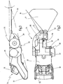
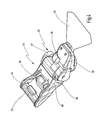
Fig. 1 ist eine erfindungsgemäße Vorrichtung insgesamt mit der Ziffer 10 bezeichnet. - Die Vorrichtung 10 umfasst eine Wickeleinrichtung 24 zum Aufwickeln eines Schneidmittels 18, das zum Durchtrennen eines Klebewulstes 34 einer Fahrzeugscheibe 12 dient.
- Bei der Fahrzeugscheibe 12 kann es sich beispielsweise um eine Windschutzscheibe eines Kraftfahrzeugs handeln, die mittels des Klebewulstes 34, der aus einem sehr zähen Kunststoffmaterial, wie etwa Polyurethankleber, besteht, mit einem Karosserieflansch 14 verklebt ist. Der Klebewulst 34 ist äußerst stabil und trägt zur Eigenstabilität des Fahrzeugs bei.
- Wenn ein derartiger Klebewulst 34 mit Hilfe eines Schneidmittels 18 in Form eines Drahtes oder dgl. durchtrennt werden soll, so ist offensichtlich, dass hierzu eine erhebliche Kraft notwendig ist.
- Die Wickeleinrichtung 24 weist ein Gehäuse 20 auf, an dessen einem Ende ein Handgriff 22 vorgesehen ist. Ausgehend vom Handgriff 22 verjüngt sich das Gehäuse 20 gemäß
Fig. 3 etwa keilförmig zum gegenüberliegenden Ende hin, an dem eine Stütze 32 abnehmbar befestigt ist. Das Schneidmittel 18 kann mittels eines elektrischen Antriebes 26 auf einer Spule 28 aufgewickelt bzw. davon abgespult werden. Zur Führung des Schneidmittels 18 zur Spule 28 sind an der Stütze 32 zwei Führungsrollen 50, 52 vorgesehen, durch die ein weitgehend tangentiales Aufwickeln des Schneidmittels 18 auf der Spule gewährleistet wird. - Um eine Fahrzeugscheibe 12, etwa eine Windschutzscheibe, aus einem Fahrzeug auszutrennen, wird zunächst das Schneidmittel 18 vollständig von außen um den Klebewulst 34 herum geführt. Sodann wir ein erstes Ende entweder von außen an einem feststehenden Fahrzeugteil, z.B. an der Scheibenwischerwelle befestigt oder aber mit Hilfe eines Saugtellers an der Fahrzeugscheibe selbst von außen oder von innen, wozu ein vorheriges Durchführen durch den Klebewulst 34 erforderlich ist. Sodann wird das zweite Ende des Schneidmittels 18 durch den Klebewulst 34 hindurchgeführt und an der Wickeleinrichtung 24 befestigt. Die Wickeleinrichtung 24 wird nunmehr mit ihrer Stütze 32 am Rahmen oder Karosserieflansch 14 abgestützt und der Antrieb der Wickeleinrichtung 26 betätigt. Dadurch wird das Schneidmittel 18 nach und nach durch den Klebewulst 34 hindurchgezogen, so dass dieser durchtrennt wird. Der Winkel 42 zwischen dem Schneidmittel 18 und dem Karosserieflansch 14 soll hierbei möglichst klein gehalten werden, wodurch eine gute Schneidwirkung erzielt wird. Die Wickeleinrichtung 24 wird somit nach und nach gemäß dem Fortschritt des Schneidvorgangs mit der Stütze 32 am Rahmen 14 entlang geführt, so dass der Winkel zwischen Schneidmittel und Karosserieflansch 14 nicht zu groß wird, wie in
Fig. 1 durch die gestrichelt gezeichnete Position des Schneidmittels 18' und den Winkel 42' angedeutet. Es ist auch denkbar, die Stütze 32 entlang des Klebewulstes 34 zu führen. - Der Aufbau der in
Fig. 1 lediglich rein schematisch angedeuteten Wickeleinrichtung 24 wird im Folgenden anhand derFig. 2 bis 4 näher beschrieben. - Die Stütze 32, an der die Führungsrollen 50, 52 vorgesehen sind, ist mittels einer Spanneinrichtung 80 abnehmbar am Gehäuse 20 der Wickeleinrichtung 24 befestigt (vgl.
Fig. 2 ). Der Antrieb 26 weist einen Gleichstrommotor 27 auf, der über ein Getriebe 29 mit der Spule 28 zu deren Antrieb gekoppelt ist. - Der Motor 27 wird von einem Akkumulator 30 mit Strom versorgt, der auswechselbar am Gehäuse 20 befestigt ist. Es versteht sich, dass stattdessen jedoch auch eine netzgetriebene Ausführung zum Einsatz kommen kann oder dass jede andere geeignete Antriebsart, z.B. ein Druckluftantrieb verwendet werden kann.
- Beim Antrieb der Spule 28 wird das Schneidmittel 18 in Arbeitsrichtung über die Führungsrollen 50, 52 durch eine Öffnung 70 auf der Spule 28 aufgewickelt.
- Aus
Fig. 3 ist erkennbar, dass sich das Gehäuse 20 der Wickeleinrichtung 24 ausgehend vom Handgriff 22 etwa keilförmig mit einem Winkel α von ca. 13° zum gegenüberliegenden Ende hin verjüngt, an dem die Stütze 32 befestigt ist. Je nach Konstruktion liegt der Winkel α vorzugsweise in einem Bereich von etwa 10 bis 30°. - Durch diese Gestaltung ist die Wickeleinrichtung 24 an ihrem dem Karosserieflansch 14 während des Einsatzes zugewandten Ende relativ schmal ausgebildet, so dass eine Abstützung am Rahmen oder Karosserieflansch 14 auch bei Hindernissen, wie sie an Armaturenbrettern vorkommen, relativ einfach möglich ist. Es versteht sich, dass hierzu eine jeweils geeignete Stütze 32 verwendet werden kann, die an die geometrischen Verhältnisse bei dem jeweiligen Fahrzeugmodell angepasst ist.
- Der Austrennvorgang durch Aufwickeln des Schneidmittels 18 auf der Spule 28 in Arbeitsrichtung muss in der Regel mehrfach unterbrochen werden, da die Wickeleinrichtung 24 an Hindernissen am Armaturenbrett vorbeibewegt werden muss und erneut mit der Stütze 32 am Rahmen oder Karosserieflansch 14 angesetzt werden muss. Teilweise ist hierzu ein zwischenzeitliches Herausziehen des Schneidmittels 18 aus der Spule 28 erforderlich.
- Da das Schneidmittel 18 in Folge der starken Getriebeuntersetzung in der Regel nur mit großem Kraftaufwand entgegen der Arbeitsrichtung von der Spule 28 abgewickelt werden kann, ist erfindungsgemäß eine Zugentlastungseinrichtung 36 vorgesehen. Die Zugentlastungseinrichtung 36 kann eine mechanische Freilaufkupplung umfassen, die mit dem Getriebe 29 unmittelbar gekoppelt ist. Dadurch wird ein Herausziehen des Schneidmittels 18 aus der Spule 28 ermöglicht, wenn der Antrieb 26 nicht aktiviert ist.
- Bevorzugt ist die Wickeleinrichtung 24 jedoch mit einer intelligenten Steuerung 46 versehen, die bei abgeschaltetem Antrieb 26 erkennt, dass eine Kraft auf das Schneidmittel 18 ausgeübt wird, um dieses aus der Spule 28 herauszuziehen. Die Wickeleinrichtung 24 unterstützt den Anwender in diesem Fall, indem die Spule 28 entgegen der Arbeitsrichtung angetrieben wird, so dass das Schneidmittel 18 von der Spule 28 wieder abgewickelt wird. Die Anordnung ist vorzugsweise nun so getroffen, dass das Schneidmittel 18 umso schneller abgewickelt wird, je größer die auf das Schneidmittel 18 ausgeübte Zugkraft ist. Der Abwickelvorgang wird beendet, sobald der Anwender nicht mehr an der Wickeleinrichtung 24 zieht, oder wenn ein Schalter 44 zur Aktivierung des Antriebs 26 betätigt wird.
- Auf diese Weise ist ein sehr komfortables Abwickeln des Schneidmittels 18 ermöglicht, wenn die Wickeleinrichtung 24 an einen anderen Ort versetzt werden muss und hierzu ein Abwickeln des Schneidmittels 18 notwendig ist.
- Der Schalter 44 ist als Gasgebeschalter ausgebildet und ist gemäß
Fig. 4 unmittelbar am Griff 22 aufgenommen. Der Gasgebeschalter 44 wird über einen Drücker betätigt. Über den Gasgebeschalter 44 kann der Anwender die gewünschte Spulendrehzahl und somit die Schneidgeschwindigkeit steuern. - Im Antriebsstrang integriert ist ferner eine mechanische Kupplung, die in
Fig. 4 mit 49 angedeutet ist. Die Kupplung 49 schützt das Schneidmittel 18 vor Überlastung und Bruch. Dieser Überlastungsschutz 49 löst aus, sobald die maximal zulässige Zugkraft am Schneidmittel 18 erreicht wird. Löst der Überlastungsschutz 49 aus, so wird dies dem Anwender signalisiert, wozu ein optisches und/oder akustisches Signalmittel 48 vorgesehen ist. Auch wenn die Zugentlastungseinrichtung 36 aktiviert ist, um das Schneidmittel entgegen der Arbeitsrichtung aus der Spule 28 herausziehen zu können, so wird dies durch ein entsprechendes Signal angezeigt, wozu gleichfalls das Signalmittel 48 verwendet werden kann. Es können beispielsweise unterschiedliche Signaltöne für die Aktivierung der Zugentlastungseinrichtung 36 und für die Aktivierung des Überlastschutzes 49 verwendet werden. Alternativ kann auch eine mechanische Anzeige z.B. in Form einer Ratsche oder einer Vibration verwendet werden.
Claims (12)
- Vorrichtung zum Durchtrennen des Klebewulstes (34) einer Fahrzeugscheibe (12), insbesondere einer Windschutzscheibe, mit einer Wickeleinrichtung (24), mit einer Spule (28) zum Aufwickeln eines Schneidmittels (18) in Arbeitsrichtung zum Durchtrennen des Klebewulstes (34), wobei die Wickeleinrichtung (24) einen motorischen Antrieb (26) umfasst, der mit einer Steuerung (46) mit einem Schalter (44) zum Einschalten des Antriebs (26) gekoppelt ist, dadurch gekennzeichnet, dass die Wickeleinrichtung (24) eine Zugentlastungseinrichtung (36) für das Schneidmittel (18) aufweist, die ein Herausziehen des Schneidmittels (18) aus der Wickeleinrichtung (24) entgegen der Arbeitsrichtung erlaubt, und dass die Steuerung (46) derart ausgebildet ist, dass der Antrieb (26) nach einem Ausschalten für eine bestimmte Zeitspanne entgegen der Arbeitsrichtung gedreht wird.
- Vorrichtung nach Anspruch 1, dadurch gekennzeichnet, dass der Antrieb (26) zur Zugentlastung des Schneidmittels (18) zwischen Rechts- und Linkslauf umschaltbar ist.
- Vorrichtung nach Anspruch 1 oder 2, dadurch gekennzeichnet, dass die Zugentlastungseinrichtung (36) eine mechanische Freilaufkupplung aufweist.
- Vorrichtung nach einem der Ansprüche 1 bis 3, dadurch gekennzeichnet, dass die Steuerung (46) derart ausgebildet ist, dass der Antrieb (26) das Schneidmittel (18) wieder auf den Ausgangszustand aufspult, wenn nach dem Ausschalten des Antriebs (26) keine Zugkraft auf das Schneidmittel (18) ausgeübt wird.
- Vorrichtung nach Anspruch 1 oder 2, dadurch gekennzeichnet, dass die Steuerung (46) derart ausgebildet ist, dass das Schneidmittel (18) nach einem Ausschalten des Antriebs (26) abgespult wird, wenn eine Zugkraft auf das Schneidmittel (18) ausgeübt wird.
- Vorrichtung nach Anspruch 5, dadurch gekennzeichnet, dass die Steuerung (46) derart ausgebildet ist, dass das Schneidmittel (18) um so schneller abgespult wird, je größer die auf das Schneidmittel (18) ausgeübte Zugkraft ist.
- Vorrichtung nach Anspruch 5 oder 6, dadurch gekennzeichnet, dass die Steuerung (46) derart ausgebildet ist, dass der Abspulvorgang beendet wird, wenn keine Zugkraft mehr auf das Schneidmittel (18) ausgeübt wird.
- Vorrichtung nach einem der vorhergehenden Ansprüche, dadurch gekennzeichnet, dass ein Signalmittel (48) vorgesehen ist, das eine Aktivierung der Zugentlastungseinrichtung (36) signalisiert.
- Vorrichtung nach einem der vorhergehenden Ansprüche, dadurch gekennzeichnet, dass der Antrieb (26) einen Überlastungsschutz (44) aufweist, dessen Ansprechen über ein Signalmittel (48) angezeigt wird.
- Vorrichtung nach Anspruch 9, dadurch gekennzeichnet, dass der Überlastungsschutz (49) eine mechanisch auslösbare Kupplung umfasst.
- Vorrichtung nach einem der vorhergehenden Ansprüche, dadurch gekennzeichnet, dass die Wickeleinrichtung (24) einen mit der Spule (28) gekoppelten Antrieb (26) aufweist, dass die Wickeleinrichtung (24) einen Griff (22) an einem ersten Ende aufweist, und dass die Wickeleinrichtung (24) am dem Griff (22) gegenüberliegenden zweiten Ende eine abnehmbare Stütze (32) zur Führung der Wickeleinrichtung (24) an einem Rahmen (14), mit dem die Scheibe (12) verklebt ist, oder am Klebewulst (34) aufweist.
- Vorrichtung nach Anspruch 10 oder 11, dadurch gekennzeichnet, dass die Wickeleinrichtung ein Gehäuse (20) aufweist, dass ausgehend von der Stütze (32) zum Griff (22) annähernd keilförmig ausgebildet ist.
Applications Claiming Priority (1)
| Application Number | Priority Date | Filing Date | Title |
|---|---|---|---|
| DE200810060802 DE102008060802A1 (de) | 2008-12-01 | 2008-12-01 | Vorrichtung zum Durchtrennen des Klebewulstes von eingeklebten Scheiben |
Publications (3)
| Publication Number | Publication Date |
|---|---|
| EP2191945A2 EP2191945A2 (de) | 2010-06-02 |
| EP2191945A3 EP2191945A3 (de) | 2010-07-07 |
| EP2191945B1 true EP2191945B1 (de) | 2015-06-03 |
Family
ID=41683448
Family Applications (1)
| Application Number | Title | Priority Date | Filing Date |
|---|---|---|---|
| EP09177355.6A Not-in-force EP2191945B1 (de) | 2008-12-01 | 2009-11-27 | Vorrichtung zum Durchtrennen des Klebewulstes von eingeklebten Scheiben |
Country Status (4)
| Country | Link |
|---|---|
| US (1) | US8307873B2 (de) |
| EP (1) | EP2191945B1 (de) |
| CN (1) | CN101745929B (de) |
| DE (1) | DE102008060802A1 (de) |
Families Citing this family (12)
| Publication number | Priority date | Publication date | Assignee | Title |
|---|---|---|---|---|
| GB2477955B (en) * | 2010-02-19 | 2015-01-28 | Belron Hungary Kft Zug Branch | Wire handling for vehicle glazing panel cut out |
| GB2485612B (en) | 2010-11-22 | 2017-06-07 | Belron Hungary Kft - Zug Branch | Apparatus and method for cutting out a vehicle glazing panel |
| DE102011013790B4 (de) * | 2011-03-03 | 2018-03-29 | C. & E. Fein Gmbh | Vorrichtung und Verfahren zum Durchtrennen des Klebewulstes von eingeklebten Scheiben |
| DE102011013890A1 (de) | 2011-03-07 | 2012-09-13 | C. & E. Fein Gmbh | Vorrichtung und Verfahren zum Durchtrennen des Klebewulstes von eingeklebten Scheiben |
| US20140137416A1 (en) * | 2012-11-22 | 2014-05-22 | Horvath Iosif Robert | Cutting Blade Cutting Device |
| CN104044332A (zh) * | 2013-03-15 | 2014-09-17 | 纬创资通股份有限公司 | 拆解平板组的方法及拆解工具 |
| GB2526308B (en) * | 2014-05-20 | 2021-06-09 | Belron Int Ltd | Glazing panel removal |
| GB201418184D0 (en) * | 2014-10-14 | 2014-11-26 | Belron Hungary Kft Zug Branch | Apparatus and method for cutting out a vehicle glazing panel |
| US10227965B2 (en) * | 2015-03-23 | 2019-03-12 | Kent R. Mayhugh | Windshield removal assist device |
| GB201601500D0 (en) | 2016-01-27 | 2016-03-09 | Belron Hungary Kft Zug Branch | Winder unit for vehicle glazing panel cut out |
| WO2018218180A1 (en) * | 2017-05-25 | 2018-11-29 | Rolladeck Industries, Inc. | Windshield removal winch |
| CN119427447B (zh) * | 2025-01-08 | 2025-05-09 | 沈阳知为智能科技有限公司 | 一种飞机蒙皮切割装置 |
Family Cites Families (17)
| Publication number | Priority date | Publication date | Assignee | Title |
|---|---|---|---|---|
| US4215475A (en) * | 1978-06-12 | 1980-08-05 | Gould Kenneth D | Oscillating cut-out tool |
| US4227517A (en) * | 1979-01-29 | 1980-10-14 | Aguiar Robert H | Cast cutting system |
| US4601224A (en) * | 1984-10-05 | 1986-07-22 | Clark Iii William T | Hot wire cutting system |
| SE8502633D0 (sv) | 1985-05-31 | 1985-05-29 | Folksam Auto Ab | Sett och anordning for demontering |
| DE4019933A1 (de) * | 1990-06-22 | 1992-01-09 | Bayerische Motoren Werke Ag | Schneidvorrichtung zum entfernen von klebstoffraupen bei geklebten fahrzeugscheiben |
| US5622093A (en) * | 1995-01-19 | 1997-04-22 | Equalizer Industries, Inc. | Automobile windshield removal apparatus and method |
| AUPN743896A0 (en) * | 1996-01-05 | 1996-02-01 | Lock, Trevor Stanley | Improvements in windscreen removal devices |
| DE29711291U1 (de) * | 1997-06-28 | 1997-09-04 | Eduard Wille Gmbh & Co, 42349 Wuppertal | Scheibentrenngerät |
| US6616800B2 (en) * | 2001-03-05 | 2003-09-09 | Rolf O. Eriksson | Method and device for removing windshields |
| US20060117573A1 (en) * | 2002-08-09 | 2006-06-08 | Mobilglas 2000Aps | Apparatus and method for guiding a tool along a path on a surface |
| NL1022127C2 (nl) * | 2002-12-10 | 2004-06-11 | Tetra Pak Tebel Bv | Kaasvat voor het bereiden van zachte verse kaas. |
| DE60332286D1 (de) | 2003-05-21 | 2010-06-02 | Ramhuset Dala Speglar Ab | Verfahren und vorrichtung zur entfernung von fahrzeugfenstern |
| US20080012349A1 (en) * | 2005-09-14 | 2008-01-17 | William Finck | Vehicle Glazing Panel Cut Out |
| DE102006013417A1 (de) | 2006-03-14 | 2007-09-20 | C. & E. Fein Gmbh | Vorrichtung und Verfahren zum Durchtrennen des Klebewulstes einer Fahrzeugscheibe |
| CN101500753B (zh) * | 2006-06-30 | 2010-12-01 | 国立大学法人长崎大学 | 切断方法及切断装置 |
| US20090283214A1 (en) * | 2008-05-16 | 2009-11-19 | Jack Richard Nelson | Device and method for separating adhesive |
| EP2191943B1 (de) * | 2008-12-01 | 2013-01-16 | C. & E. Fein GmbH | Vorrichtung und Verfahren zum Durchtrennen des Klebewulstes von eingeklebten Scheiben |
-
2008
- 2008-12-01 DE DE200810060802 patent/DE102008060802A1/de not_active Withdrawn
-
2009
- 2009-11-27 EP EP09177355.6A patent/EP2191945B1/de not_active Not-in-force
- 2009-12-01 US US12/628,660 patent/US8307873B2/en not_active Expired - Fee Related
- 2009-12-01 CN CN200910252804.XA patent/CN101745929B/zh not_active Expired - Fee Related
Also Published As
| Publication number | Publication date |
|---|---|
| EP2191945A2 (de) | 2010-06-02 |
| EP2191945A3 (de) | 2010-07-07 |
| US20100132201A1 (en) | 2010-06-03 |
| CN101745929A (zh) | 2010-06-23 |
| CN101745929B (zh) | 2014-05-14 |
| US8307873B2 (en) | 2012-11-13 |
| DE102008060802A1 (de) | 2010-06-02 |
Similar Documents
| Publication | Publication Date | Title |
|---|---|---|
| EP2191945B1 (de) | Vorrichtung zum Durchtrennen des Klebewulstes von eingeklebten Scheiben | |
| EP2191943B1 (de) | Vorrichtung und Verfahren zum Durchtrennen des Klebewulstes von eingeklebten Scheiben | |
| EP0093283B1 (de) | Verfahren und Vorrichtung zum Ablösen von Fahrzeugscheiben | |
| EP1834741A1 (de) | Vorrichtung und Verfahren zum Durchtrennen des Klebewulstes einer Fahrzeugscheibe | |
| DE102011013890A1 (de) | Vorrichtung und Verfahren zum Durchtrennen des Klebewulstes von eingeklebten Scheiben | |
| EP2039547A2 (de) | Seitenfensterrollo mit Einlaufhilfe | |
| DE102008000802B4 (de) | Vollautomatisches Staufach | |
| EP2078490B1 (de) | Elektrogerät mit einem verbesserten Kabelwickelsystem und Verfahren zum Betreiben eines Elektrogeräts | |
| EP1609647A2 (de) | Fensterrollo mit Deckel auf dem Auszugsschlitz | |
| EP1886853A1 (de) | Fensterrollo mit Antrieb über den Fensterheber | |
| DE102018211344A1 (de) | Kabelwickelsystem sowie Verfahren zum Betreiben eines Kabelwickelsystems | |
| EP2337591A1 (de) | Vorrichtung zum öffnen einer leitung | |
| DE102011013790B4 (de) | Vorrichtung und Verfahren zum Durchtrennen des Klebewulstes von eingeklebten Scheiben | |
| EP2540463B1 (de) | Vorrichtung und Verfahren zum Durchtrennen des Klebewulstes von eingeklebten Scheiben | |
| EP2565144A1 (de) | Seilwinde | |
| DE102007028585A1 (de) | Elektrisches Seitenfensterrollo | |
| DE102008060812A1 (de) | Vorrichtung und Verfahren zum Druchtrennen des Klebewulstes von eingeklebten Scheiben | |
| DE102016118948B4 (de) | Fahrzeugaufprallsystem mit einem angetriebenen Barrierewagen | |
| EP0437793A2 (de) | Trennsaite | |
| DE102009010463A1 (de) | Vorrichtung zum Durchtrennen des Klebewulstes von eingeklebten Scheiben | |
| DE102005021399A1 (de) | Rollo für Fahrzeugfenster | |
| EP0618160A2 (de) | Papierrolle, Papierrollenauspackstation und Verfahren zum Auspacken einer Papierrolle | |
| DE2455913B2 (de) | Kopswechselvorrichtung | |
| DE102008060811A1 (de) | Vorrichtung zum Durchtrennen des Klebewulstes von eingeklebten Scheiben | |
| DE102024128694A1 (de) | Handgehaltener Klebebandspender |
Legal Events
| Date | Code | Title | Description |
|---|---|---|---|
| PUAI | Public reference made under article 153(3) epc to a published international application that has entered the european phase |
Free format text: ORIGINAL CODE: 0009012 |
|
| AK | Designated contracting states |
Kind code of ref document: A2 Designated state(s): AT BE BG CH CY CZ DE DK EE ES FI FR GB GR HR HU IE IS IT LI LT LU LV MC MK MT NL NO PL PT RO SE SI SK SM TR |
|
| AX | Request for extension of the european patent |
Extension state: AL BA RS |
|
| PUAL | Search report despatched |
Free format text: ORIGINAL CODE: 0009013 |
|
| AK | Designated contracting states |
Kind code of ref document: A3 Designated state(s): AT BE BG CH CY CZ DE DK EE ES FI FR GB GR HR HU IE IS IT LI LT LU LV MC MK MT NL NO PL PT RO SE SI SK SM TR |
|
| AX | Request for extension of the european patent |
Extension state: AL BA RS |
|
| 17P | Request for examination filed |
Effective date: 20101230 |
|
| 17Q | First examination report despatched |
Effective date: 20120710 |
|
| RIC1 | Information provided on ipc code assigned before grant |
Ipc: B26D 1/547 20060101AFI20141106BHEP |
|
| GRAP | Despatch of communication of intention to grant a patent |
Free format text: ORIGINAL CODE: EPIDOSNIGR1 |
|
| INTG | Intention to grant announced |
Effective date: 20141211 |
|
| RIN1 | Information on inventor provided before grant (corrected) |
Inventor name: CLABUNDE, JOACHIM Inventor name: BLICKLE, JUERGEN Inventor name: KLABUNDE, OLAF Inventor name: MAYER, BERND |
|
| GRAS | Grant fee paid |
Free format text: ORIGINAL CODE: EPIDOSNIGR3 |
|
| GRAA | (expected) grant |
Free format text: ORIGINAL CODE: 0009210 |
|
| AK | Designated contracting states |
Kind code of ref document: B1 Designated state(s): AT BE BG CH CY CZ DE DK EE ES FI FR GB GR HR HU IE IS IT LI LT LU LV MC MK MT NL NO PL PT RO SE SI SK SM TR |
|
| REG | Reference to a national code |
Ref country code: GB Ref legal event code: FG4D Free format text: NOT ENGLISH |
|
| REG | Reference to a national code |
Ref country code: CH Ref legal event code: EP |
|
| REG | Reference to a national code |
Ref country code: AT Ref legal event code: REF Ref document number: 729675 Country of ref document: AT Kind code of ref document: T Effective date: 20150715 Ref country code: IE Ref legal event code: FG4D Free format text: LANGUAGE OF EP DOCUMENT: GERMAN |
|
| REG | Reference to a national code |
Ref country code: DE Ref legal event code: R096 Ref document number: 502009011096 Country of ref document: DE |
|
| PG25 | Lapsed in a contracting state [announced via postgrant information from national office to epo] |
Ref country code: ES Free format text: LAPSE BECAUSE OF FAILURE TO SUBMIT A TRANSLATION OF THE DESCRIPTION OR TO PAY THE FEE WITHIN THE PRESCRIBED TIME-LIMIT Effective date: 20150603 Ref country code: FI Free format text: LAPSE BECAUSE OF FAILURE TO SUBMIT A TRANSLATION OF THE DESCRIPTION OR TO PAY THE FEE WITHIN THE PRESCRIBED TIME-LIMIT Effective date: 20150603 Ref country code: HR Free format text: LAPSE BECAUSE OF FAILURE TO SUBMIT A TRANSLATION OF THE DESCRIPTION OR TO PAY THE FEE WITHIN THE PRESCRIBED TIME-LIMIT Effective date: 20150603 Ref country code: NO Free format text: LAPSE BECAUSE OF FAILURE TO SUBMIT A TRANSLATION OF THE DESCRIPTION OR TO PAY THE FEE WITHIN THE PRESCRIBED TIME-LIMIT Effective date: 20150903 Ref country code: LT Free format text: LAPSE BECAUSE OF FAILURE TO SUBMIT A TRANSLATION OF THE DESCRIPTION OR TO PAY THE FEE WITHIN THE PRESCRIBED TIME-LIMIT Effective date: 20150603 |
|
| REG | Reference to a national code |
Ref country code: NL Ref legal event code: MP Effective date: 20150603 |
|
| REG | Reference to a national code |
Ref country code: LT Ref legal event code: MG4D |
|
| PG25 | Lapsed in a contracting state [announced via postgrant information from national office to epo] |
Ref country code: LV Free format text: LAPSE BECAUSE OF FAILURE TO SUBMIT A TRANSLATION OF THE DESCRIPTION OR TO PAY THE FEE WITHIN THE PRESCRIBED TIME-LIMIT Effective date: 20150603 Ref country code: GR Free format text: LAPSE BECAUSE OF FAILURE TO SUBMIT A TRANSLATION OF THE DESCRIPTION OR TO PAY THE FEE WITHIN THE PRESCRIBED TIME-LIMIT Effective date: 20150904 Ref country code: BG Free format text: LAPSE BECAUSE OF FAILURE TO SUBMIT A TRANSLATION OF THE DESCRIPTION OR TO PAY THE FEE WITHIN THE PRESCRIBED TIME-LIMIT Effective date: 20150903 |
|
| PG25 | Lapsed in a contracting state [announced via postgrant information from national office to epo] |
Ref country code: EE Free format text: LAPSE BECAUSE OF FAILURE TO SUBMIT A TRANSLATION OF THE DESCRIPTION OR TO PAY THE FEE WITHIN THE PRESCRIBED TIME-LIMIT Effective date: 20150603 |
|
| PG25 | Lapsed in a contracting state [announced via postgrant information from national office to epo] |
Ref country code: RO Free format text: LAPSE BECAUSE OF NON-PAYMENT OF DUE FEES Effective date: 20150603 Ref country code: SK Free format text: LAPSE BECAUSE OF FAILURE TO SUBMIT A TRANSLATION OF THE DESCRIPTION OR TO PAY THE FEE WITHIN THE PRESCRIBED TIME-LIMIT Effective date: 20150603 Ref country code: PL Free format text: LAPSE BECAUSE OF FAILURE TO SUBMIT A TRANSLATION OF THE DESCRIPTION OR TO PAY THE FEE WITHIN THE PRESCRIBED TIME-LIMIT Effective date: 20150603 Ref country code: IS Free format text: LAPSE BECAUSE OF FAILURE TO SUBMIT A TRANSLATION OF THE DESCRIPTION OR TO PAY THE FEE WITHIN THE PRESCRIBED TIME-LIMIT Effective date: 20151003 Ref country code: CZ Free format text: LAPSE BECAUSE OF FAILURE TO SUBMIT A TRANSLATION OF THE DESCRIPTION OR TO PAY THE FEE WITHIN THE PRESCRIBED TIME-LIMIT Effective date: 20150603 Ref country code: PT Free format text: LAPSE BECAUSE OF FAILURE TO SUBMIT A TRANSLATION OF THE DESCRIPTION OR TO PAY THE FEE WITHIN THE PRESCRIBED TIME-LIMIT Effective date: 20151006 |
|
| REG | Reference to a national code |
Ref country code: DE Ref legal event code: R097 Ref document number: 502009011096 Country of ref document: DE |
|
| PLBE | No opposition filed within time limit |
Free format text: ORIGINAL CODE: 0009261 |
|
| STAA | Information on the status of an ep patent application or granted ep patent |
Free format text: STATUS: NO OPPOSITION FILED WITHIN TIME LIMIT |
|
| PG25 | Lapsed in a contracting state [announced via postgrant information from national office to epo] |
Ref country code: DK Free format text: LAPSE BECAUSE OF FAILURE TO SUBMIT A TRANSLATION OF THE DESCRIPTION OR TO PAY THE FEE WITHIN THE PRESCRIBED TIME-LIMIT Effective date: 20150603 Ref country code: IT Free format text: LAPSE BECAUSE OF FAILURE TO SUBMIT A TRANSLATION OF THE DESCRIPTION OR TO PAY THE FEE WITHIN THE PRESCRIBED TIME-LIMIT Effective date: 20150603 |
|
| 26N | No opposition filed |
Effective date: 20160304 |
|
| PG25 | Lapsed in a contracting state [announced via postgrant information from national office to epo] |
Ref country code: SI Free format text: LAPSE BECAUSE OF FAILURE TO SUBMIT A TRANSLATION OF THE DESCRIPTION OR TO PAY THE FEE WITHIN THE PRESCRIBED TIME-LIMIT Effective date: 20150603 |
|
| PG25 | Lapsed in a contracting state [announced via postgrant information from national office to epo] |
Ref country code: MC Free format text: LAPSE BECAUSE OF FAILURE TO SUBMIT A TRANSLATION OF THE DESCRIPTION OR TO PAY THE FEE WITHIN THE PRESCRIBED TIME-LIMIT Effective date: 20150603 Ref country code: LU Free format text: LAPSE BECAUSE OF FAILURE TO SUBMIT A TRANSLATION OF THE DESCRIPTION OR TO PAY THE FEE WITHIN THE PRESCRIBED TIME-LIMIT Effective date: 20151127 |
|
| REG | Reference to a national code |
Ref country code: CH Ref legal event code: PL |
|
| GBPC | Gb: european patent ceased through non-payment of renewal fee |
Effective date: 20151127 |
|
| PG25 | Lapsed in a contracting state [announced via postgrant information from national office to epo] |
Ref country code: CH Free format text: LAPSE BECAUSE OF NON-PAYMENT OF DUE FEES Effective date: 20151130 Ref country code: LI Free format text: LAPSE BECAUSE OF NON-PAYMENT OF DUE FEES Effective date: 20151130 |
|
| REG | Reference to a national code |
Ref country code: IE Ref legal event code: MM4A |
|
| REG | Reference to a national code |
Ref country code: FR Ref legal event code: ST Effective date: 20160729 |
|
| PG25 | Lapsed in a contracting state [announced via postgrant information from national office to epo] |
Ref country code: GB Free format text: LAPSE BECAUSE OF NON-PAYMENT OF DUE FEES Effective date: 20151127 Ref country code: IE Free format text: LAPSE BECAUSE OF NON-PAYMENT OF DUE FEES Effective date: 20151127 |
|
| PG25 | Lapsed in a contracting state [announced via postgrant information from national office to epo] |
Ref country code: FR Free format text: LAPSE BECAUSE OF NON-PAYMENT OF DUE FEES Effective date: 20151130 |
|
| REG | Reference to a national code |
Ref country code: AT Ref legal event code: MM01 Ref document number: 729675 Country of ref document: AT Kind code of ref document: T Effective date: 20151127 |
|
| PG25 | Lapsed in a contracting state [announced via postgrant information from national office to epo] |
Ref country code: AT Free format text: LAPSE BECAUSE OF NON-PAYMENT OF DUE FEES Effective date: 20151127 |
|
| PG25 | Lapsed in a contracting state [announced via postgrant information from national office to epo] |
Ref country code: SM Free format text: LAPSE BECAUSE OF FAILURE TO SUBMIT A TRANSLATION OF THE DESCRIPTION OR TO PAY THE FEE WITHIN THE PRESCRIBED TIME-LIMIT Effective date: 20150603 Ref country code: HU Free format text: LAPSE BECAUSE OF FAILURE TO SUBMIT A TRANSLATION OF THE DESCRIPTION OR TO PAY THE FEE WITHIN THE PRESCRIBED TIME-LIMIT; INVALID AB INITIO Effective date: 20091127 |
|
| PG25 | Lapsed in a contracting state [announced via postgrant information from national office to epo] |
Ref country code: NL Free format text: LAPSE BECAUSE OF FAILURE TO SUBMIT A TRANSLATION OF THE DESCRIPTION OR TO PAY THE FEE WITHIN THE PRESCRIBED TIME-LIMIT Effective date: 20150603 Ref country code: SE Free format text: LAPSE BECAUSE OF FAILURE TO SUBMIT A TRANSLATION OF THE DESCRIPTION OR TO PAY THE FEE WITHIN THE PRESCRIBED TIME-LIMIT Effective date: 20150603 Ref country code: CY Free format text: LAPSE BECAUSE OF FAILURE TO SUBMIT A TRANSLATION OF THE DESCRIPTION OR TO PAY THE FEE WITHIN THE PRESCRIBED TIME-LIMIT Effective date: 20150603 |
|
| PG25 | Lapsed in a contracting state [announced via postgrant information from national office to epo] |
Ref country code: BE Free format text: LAPSE BECAUSE OF NON-PAYMENT OF DUE FEES Effective date: 20151130 |
|
| PG25 | Lapsed in a contracting state [announced via postgrant information from national office to epo] |
Ref country code: TR Free format text: LAPSE BECAUSE OF FAILURE TO SUBMIT A TRANSLATION OF THE DESCRIPTION OR TO PAY THE FEE WITHIN THE PRESCRIBED TIME-LIMIT Effective date: 20150603 Ref country code: MT Free format text: LAPSE BECAUSE OF FAILURE TO SUBMIT A TRANSLATION OF THE DESCRIPTION OR TO PAY THE FEE WITHIN THE PRESCRIBED TIME-LIMIT Effective date: 20150603 |
|
| PGFP | Annual fee paid to national office [announced via postgrant information from national office to epo] |
Ref country code: DE Payment date: 20171121 Year of fee payment: 9 |
|
| PG25 | Lapsed in a contracting state [announced via postgrant information from national office to epo] |
Ref country code: MK Free format text: LAPSE BECAUSE OF FAILURE TO SUBMIT A TRANSLATION OF THE DESCRIPTION OR TO PAY THE FEE WITHIN THE PRESCRIBED TIME-LIMIT Effective date: 20150603 |
|
| REG | Reference to a national code |
Ref country code: DE Ref legal event code: R119 Ref document number: 502009011096 Country of ref document: DE |
|
| PG25 | Lapsed in a contracting state [announced via postgrant information from national office to epo] |
Ref country code: DE Free format text: LAPSE BECAUSE OF NON-PAYMENT OF DUE FEES Effective date: 20190601 |