EP2191238B1 - Vorrichtung und verfahren zur messung von verschiebungen von verschiebbaren gliedern - Google Patents
Vorrichtung und verfahren zur messung von verschiebungen von verschiebbaren gliedern Download PDFInfo
- Publication number
- EP2191238B1 EP2191238B1 EP08789861.5A EP08789861A EP2191238B1 EP 2191238 B1 EP2191238 B1 EP 2191238B1 EP 08789861 A EP08789861 A EP 08789861A EP 2191238 B1 EP2191238 B1 EP 2191238B1
- Authority
- EP
- European Patent Office
- Prior art keywords
- machine
- displacement
- displaceable member
- sensible
- pulse generator
- Prior art date
- Legal status (The legal status is an assumption and is not a legal conclusion. Google has not performed a legal analysis and makes no representation as to the accuracy of the status listed.)
- Active
Links
- 238000006073 displacement reaction Methods 0.000 title claims description 79
- 238000000034 method Methods 0.000 title claims description 10
- 230000002093 peripheral effect Effects 0.000 claims 1
- 230000008901 benefit Effects 0.000 description 6
- 230000015654 memory Effects 0.000 description 6
- 235000014676 Phragmites communis Nutrition 0.000 description 3
- 238000005259 measurement Methods 0.000 description 3
- 230000004913 activation Effects 0.000 description 2
- 230000006870 function Effects 0.000 description 2
- 230000003287 optical effect Effects 0.000 description 2
- 230000001133 acceleration Effects 0.000 description 1
- 239000003990 capacitor Substances 0.000 description 1
- 238000010276 construction Methods 0.000 description 1
- 230000007423 decrease Effects 0.000 description 1
- 230000003247 decreasing effect Effects 0.000 description 1
- 238000010586 diagram Methods 0.000 description 1
- 230000005611 electricity Effects 0.000 description 1
- 230000006698 induction Effects 0.000 description 1
- 238000012986 modification Methods 0.000 description 1
- 230000004048 modification Effects 0.000 description 1
- 230000007704 transition Effects 0.000 description 1
Images
Classifications
-
- G—PHYSICS
- G01—MEASURING; TESTING
- G01D—MEASURING NOT SPECIALLY ADAPTED FOR A SPECIFIC VARIABLE; ARRANGEMENTS FOR MEASURING TWO OR MORE VARIABLES NOT COVERED IN A SINGLE OTHER SUBCLASS; TARIFF METERING APPARATUS; MEASURING OR TESTING NOT OTHERWISE PROVIDED FOR
- G01D5/00—Mechanical means for transferring the output of a sensing member; Means for converting the output of a sensing member to another variable where the form or nature of the sensing member does not constrain the means for converting; Transducers not specially adapted for a specific variable
- G01D5/12—Mechanical means for transferring the output of a sensing member; Means for converting the output of a sensing member to another variable where the form or nature of the sensing member does not constrain the means for converting; Transducers not specially adapted for a specific variable using electric or magnetic means
- G01D5/244—Mechanical means for transferring the output of a sensing member; Means for converting the output of a sensing member to another variable where the form or nature of the sensing member does not constrain the means for converting; Transducers not specially adapted for a specific variable using electric or magnetic means influencing characteristics of pulses or pulse trains; generating pulses or pulse trains
Definitions
- the present invention relates to apparatus and methods for measuring displacements of a displaceable member along a predetermined displacement path.
- the invention is described below particularly with respect to rotary displaceable members such as in rotary encoders, but may also be used with respect to linearly-displaceable members, such as in linear encoders.
- the displacement of rotary members is usually measured by counting the number of turns or revolutions experienced by the rotary member as well as fractions thereof, which fractions determine the resolution of the measurement apparatus.
- Turn counting is needed for example in absolute encoders mounted on motors, e.g., as explained in US Patent 6,628,741 by Netzer.
- Turn counting systems are used in rotary encoders to provide absolute position information of high precision even when there is an interruption of the power supply to the system and the shaft to be monitored has been turning during these power supply interruptions.
- Many absolute encoders use batteries in order to monitor and record the turn counting while external power is interrupted.
- the use of battery has a number of drawbacks.
- batteries have a limited life time.
- replacing a battery without losing the recorded turn counting requires special circuitry, for example a large capacitor, to back up the recorded data during the battery replacement, which circuitry results in additional cost of the encoder.
- batteries tolerate a limited range of temperatures, and therefore where the encoders are to be used in high temperature environments, the battery cannot be placed inside the encoder.
- Patents US 5,565,769 and US 5,714,882 describe systems that are able to count and register the number of turns of a shaft without a battery; however, these systems are sensitive to vibrations.
- Patent US 6,628,741B1 describes apparatus to implement a turns counter without a battery by using a reed relay; however reed relays are sensitive to vibrations, have a limited life time, and can be damaged or destroyed in case of high accelerations.
- Another drawback is that the amount of energy produced in order to count and store the number of turns is very small, which limits the system to the use of ferroelectric memories; unfortunately, these memories are not available in small sizes, and this again limits their application in encoders.
- An object of the present invention is to provide apparatus, and also a method, for measuring displacements of a displaceable member having advantages in one or more of the above respects.
- apparatus for measuring displacements of a displaceable member along a predetermined displacement path by counting periods of displacement thereof along said predetermined displacement path, said apparatus, comprising:
- the first and second machine-sensible elements are magnetic elements
- the pulse generator includes a coil, a magnetic core magnetically coupled to the coil, and a spring-mounting for the magnetic core causing the core to move from an initial position in one direction with respect to the coil when aligned with one of the second machine-sensible elements, and to be returned in the opposite direction by the spring to its initial position, whereby the coil generates a pulse during each such movement of the magnetic core.
- the displaceable member is a rotary member, and the counter counts the number of periods of rotation and fractions thereof of the rotary member.
- the displaceable member is a linearly-displaceable member, and the counter counts the number of periods of linear displacements and fractions thereof experienced by the displaceable member.
- a method for measuring displacements of a displaceable member along a predetermined displacement path, by counting periods of displacement thereof along said predetermined displacement path comprising:
- the apparatus and method of the present invention as briefly described above enable measuring the displacement of a displaceable member in a manner which does not require a battery, which uses standard electronic devices, and which is relatively insensitive to vibrations.
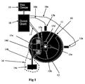
- FIG. 1 schematically illustrating one form of measuring apparatus constructed in accordance with the present invention for measuring the turns or rotations of a shaft 10 about a rotary axis 11.
- the apparatus illustrated in FIG. 1 may be in the form of a stand-alone turns counter, or a one-turn absolute encoder providing a precise measurement of the rotation angle of the shaft.
- the apparatus illustrated in FIG. 1 is designed for recording the number of turns and/or fractions of a turn, without the need for external power, since the required power is received from the rotating shaft by means of magnetic induction.
- the rotary shaft 10 itself, whose rotations are to be counted, or a separate disc fixed to that shaft, includes a first machine-sensible element 12 extending around the outer circumference of the shaft for a length defining one-half of a period of displacement (one rotation) of the shaft.
- machine-sensible element 12 covers one-half the circumference of shaft 10, leaving the other half uncovered. Accordingly, each full rotation or turn of shaft 10 is constituted of a single period, one-half of which is occupied by machine-sensible element 12, whereas the other half is not occupied by that element.
- the apparatus illustrated in FIG. 1 further includes at least one sensor, preferably two sensors, 13a, 13b, spaced from each other.
- Sensors 13a, 13b are located at sensing stations proximate to the displacement path of rotary shaft 10 so as to be capable of sensing the presence or absence of machine-sensible element 12 in the sensing station, and thereby of determining the status of the shaft 10 at any particular instant during the rotation of the shaft.
- machine-sensible element 12 is a magnetic element
- the two sensors 13a, 13b are Hall sensors spaced 90° from each other around the outer surface of shaft 10.
- the apparatus illustrated in FIG. 1 further includes a pulse generator, generally designated 14, fixed at another location, called a pulse generation station, proximate to the rotary shaft 10.
- Pulse generator 14 includes a magnetic core 14a mounted in cantilever fashion at one end of an elastic arm 14b, whose opposite end is fixed at 14c, and is movable with respect to a coil 14d to generate a pulse therein upon each movement of the core with respect to the coil.
- Shaft 10 further carries a plurality of second machine-sensible elements 15a-15d equally spaced in a circular array around the axis of rotation 11 of the shaft.
- Machine-sensible elements 15a-15d are also magnets, so as to attract magnetic core 14a of pulse generator 14 to generate in coil 14d a pulse each time a magnetic element 15a-15d moves proximately to, and away from, core 14a of the pulse generator.
- Each of the two sensors 13a, 13b is connected by leads 16a, 16b, and coil 14d of pulse generator 14 is connected by leads 17, to an electrical control circuit 18, which circuit controls a turns counter 19.
- the system illustrated in FIG. 1 operates as follows:
- the four magnets 15a-15d When shaft 10 rotates, the four magnets 15a-15d also rotate around rotary axis 11, such that each of the four magnets 15a-15d move towards, and then away from, core 14a of pulse generator 14. With each such movement of a magnet 15a-15d with respect to core 14a, the latter core is abruptly moved towards or away from coil 14d, to thereby generate a pulse within the coil with each such movement. These pulses are fed via lead 17 to the electrical control circuit 18. Each such pulse, generated in coil 14d and applied to electrical control circuit 18 via lead 17, activates the electrical circuit for a short period of time during which the electrical circuit enables sensors 13a, 13b to register the rotary position of shaft 10 at that instant.
- Sensors 13a, 13b thus serve as status sensors, determining the status of the shaft at any particular instant, namely the instant at which electrical circuit 18 receives a pulse from pulse generator 14.
- Electrical circuit 18 also controls a turns counter 19, which accumulates, in a non-volatile memory, the absolute position of the shaft by counting the number of periods (rotations) and functions thereof traversed by the shaft.
- magnets 15a-15d are spaced 90° from each other, the rotary position of the shaft can be determined with a resolution of one-quarter of a turn. Also, since there are two status sensors 13a, 13b, located 90° with respect to each other, the measuring system is able to distinguish the direction of the respective increment of rotation, i.e., whether in the forward direction or in the reverse direction.
- a pulse is outputted by the pulse generator 14 each time a magnet 15a-15d moves towards core 14a and then away from the core, and that each such pulse produced in core 14d is not linear, but sharply increases as the magnet moves towards the core, and sharply decreases as the magnet moves away from the core. It will be further seen that these movements of the core will generate energy to activate the turns counter 19.
- the amount of energy available from the pulse generator 14 is large enough to allow the storage of the shaft position in a non-volatile memory, like a ferroelectric memory, a flash memory, or an EPROM.
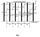
- FIG. 2 illustrates the sequence of states involved in the apparatus illustrated in FIG. 1 , wherein one turn to be counted is constituted of one period since there is only one magnet 12 extending for one-half the circumference of the shaft.
- Increment Table used to update the number of turns of the shaft in accordance with the sequence of states in FIG. 2 .
- Increment Table Sensor 1 13a
- Sensor 2 13b
- each sensor 13a, 13b is shown in FIG. 2 in relation to the rotation angle.
- the states of each sensor is represented by two values indicating whether the sensor is close to the sensible element or not. Whenever the electronic circuit 18 is activated, then each sensor state is sensed by the electronic circuit.
- FIG. 2 also shows, as grey areas 23, the range of angles when the pulse generator 14 outputs pulses to cause the electrical circuit 18 to activate the turns counters 19.
- a sector can be defined as a range of angles for which the state of sensors 13a, 13b is constant.
- four sector s0-s3 are defined in one turn 24, and the pulse generator outputs one pulse of energy between two transitions of the states 21 or 22.
- the electric circuit 18 and turns counter 19 are activated at least once each time shaft 10 moves at least one quarter of a turn, such that there will always be at least one update of the position measurement for each one quarter of a turn.
- Hall sensors are used because they provide sensing with minimum power consumption.
- other types of sensors can be used, such as reed relays, proximity sensors, or other types of sensors.
- the machine-sensible elements 12 and 15a-15d are magnetic elements which generate the required electricity and therefore do not need a battery.
- such elements could be optical elements, rather than magnetic elements, whereupon the status sensors 13a, 13b, as well the pulse generator 14, would be optically activated rather than magnetically activated.
- sectors in the preferred embodiment are shown covering a 90 degrees range of angle; however sectors can be of different sizes, so long as that there is at least one activation of the pulse generator in the range of each sensor.
- a particular advantage of the apparatus illustrated is that it does not count the number of pulses outputted by the pulse generator, but rather such pulses are used to provide energy to a separate turns counter 19.
- the described system is not sensitive to vibrations. If vibrations occur, and these vibrations result in a movement of the moving core 14a of the pulse generator 14, and a pulse of energy is outputted more than once in a quarter of a turn, then the increment by one quarter of a turn will be done only for the first pulse; the following pulse will result in a zero increment value.
- This is clearly shown in the above Increment Table, wherein the position increment is given as a function of the present states of the sensors and the previous states as sensed by the electronic circuit 18 and the turns counter 19.
- the electronic circuit 18 checks, at a high rate, the states of the sensors, and updates the shaft position according to the table. The checking cycle is short enough so that the shaft position will be updated even if the shaft has a high rotational speed.
- a sector is defined as a range of angles for which the state of sensors 13a and 13b remains constant.
- the preferred embodiment illustrated shows sectors of exactly one quarter of a turn; however the sectors may be of different sizes, as long as there is at least one activation of the pulse generator within one sector, i.e. at least one of the second sensible member activates the pulse generator within the sector range.
- the turn counting resolution is one-fourth of a turn, i.e., one-fourth of a period, using only two sensors.
- Another advantage of the illustrated apparatus is that only one magnetic energy generating element, i.e., pulse generator 14, is used for a bi-directional turn counter. This is to be sharply distinguished from the systems illustrated in the above-cited US Patents, which need at least three magnetic energy generating elements in order to count in both directions.
- the apparatus is used to count the number of turns of a shaft, each turn representing a period of displacement, with one-quarter of a turn resolution. It will be appreciated that the same apparatus can include a counting system having a different resolution than one-quarter turn by providing a different number of magnets 12 (or other machine-sensible elements), to thereby define a different number of sectors of the shaft to produce at least one pulse of energy per sector.
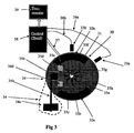
- FIG. 3 illustrates an apparatus wherein the shaft 30 is divided into eight sectors by eight magnets 35a-35h equally arranged in a circular array around the rotary axis 31 of the shaft.
- an inner magnet 35a-35d
- the apparatus illustrated in FIG. 3 includes a pulse generator, generally designated 34, including a movable core 34a secured to one end of an elastic member 34b whose opposite end 34c is fixed, and movable within a coil 34d when each of the inner magnets 35a-35h passes into and out of alignment with the magnetic core 34a.
- the pulses generated by coil 34d are applied to electrical circuit 38 via leads 37; and the status of each of the status sensors 33a, 33b, with respect to the outer magnets 32a, 32b, is fed to electrical circuit 38 via leads 36a and 36b from the two status sensors 33a, 33b.
- Electrical circuit 38 thus increments (or decrements) turns counter 39 according to the sensed status, as described above with respect to FIGs. 1 and 2 .
- FIG. 3 has a resolution of one-eighth of a turn, rather than one-quarter of a turn as in FIGs. 1 and 2 .
- a displacement measuring system constructed in accordance with the present invention may be based on more than one or two periods for each turn by providing the rotary shaft with the appropriate number of outer magnets (12), namely one for each such period and extending for one-half the distance of the respective period. It will also be appreciated that the apparatus may be constructed to provide a different number of sectors, and thereby a different resolution, by providing the appropriate number of inner magnets to actuate the pulse generator at least once for each sector during each rotation.
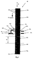
- FIG. 4 schematically illustrates the invention implemented in apparatus for measuring linear displacements in the form of linear displacement periods and fractions thereof along a linear displacement path, rather than rotary displacements as in FIGs. 1-3 .
- the apparatus illustrated in FIG. 4 includes a linearly-displaceable member, generally designated 40, displaceable in a linear path as indicated by arrow 41.
- Displaceable member 40 includes, on one side, a plurality of machine-sensible elements, namely magnets 42a-42g, one for each period of displacement of member 40, with each such magnet covering one-half the period.
- the respective side of displaceable member 40 further includes two status sensors 43a, 43b.
- pulse generator 44 including a movable core 44a carried at one end of an elastic arm 44b, with the opposite end of the elastic arm 44c fixedly mounted, and with the core 44a movable with respect to a coil 44d to generate an electrical pulse with each movement of the coil.
- pulse generator 44 is actuated by a plurality of magnets 45a-45n, corresponding to the number of periods defined by magnets 42a-42g and the resolution desired in the measuring apparatus.
- magnets 42a-42g divide the length of the displaceable member into seven periods 46
- the magnets 45a-45n divide each period 46 into four fractions, such that the measuring apparatus has a resolution of one-fourth period.
- the apparatus illustrated in FIG. 4 is otherwise constructed and operates in the same manner as described above with respect to FIGs. 1-3 , to measure the linear displacement of member 40 in terms of periods 46, with a resolution of one-fourth period. It will be appreciated that the distance of each period 46 is precisely known, so that the apparatus illustrated in FIG. 4 measures displacement in terms of absolute values of displacement.
- one or both of the types of machine-sensible elements could be optical elements or capacitive-type elements, rather than magnetic elements, and the pulse generator could be an optically-actuated one, rather than a magnetically-actuated one.
- the resolution of the measuring apparatus could be increased (or decreased) providing the appropriate number of magnets for actuating the pulse generator, and the appropriate spacing of the status sensors cooperable with the status magnets.
Claims (15)
- Vorrichtung zum Messen von Verschiebungen eines verschiebbaren Teils (10, 30, 40) entlang einem vorbestimmten Verschiebeweg durch das Zählen von Perioden der Verschiebung davon entlang dem vorgegebenen Verschiebeweg, wobei die Vorrichtung Folgendes umfasst:ein erstes maschinen-empfindliches Element (12, 32a, 42a), das durch den verschiebbaren Teil getragen wird und eine Länge davon einnimmt, die nur einen Abschnitt einer Periode der Verschiebung des verschiebbaren Teils definiert;einen ersten Sensor (13a, 33a, 43a), der an einer Erfassungsstation benachbart zu dem Verschiebeweg angeordnet ist, um dazu in der Lage zu sein, die Anwesenheit oder die Abwesenheit des ersten maschinen-empfindlichen Elements in der Erfassungsstation zu erfassen und dadurch den Status des verschiebbaren Teils zu jedem bestimmten Zeitpunkt während der Verschiebung des verschiebbaren Teils zu bestimmen;einen Impulserzeuger (14, 34, 44), der an einer Impulserzeugungsstation nahe dem Verschiebeweg angeordnet ist;eine Vielzahl von zweiten maschinen-empfindlichen Elementen (15a-d, 35a-h, 45an), die durch den verschiebbaren Teil in beabstandeten Intervallen entlang jeder Verschiebeperiode des Verschiebeteils getragen werden, wobei jedes der zweiten maschinen-empfindlichen Elemente wirksam ist, um den Impulserzeuger zu betätigen, wenn er sich durch die Impulserzeugungsstation bewegt;einen elektrischen Zähler (19, 39), um die Verschiebeperioden des verschiebbaren Teils zu zählen; undeine elektrische Schaltung (18, 38), die konfiguriert ist, um durch den Impulserzeuger für eine kurze Zeitdauer aktiviert zu werden, während der die elektrische Schaltung dem ersten Sensor ermöglicht, den Status des verschiebbaren Teils am bestimmten Zeitpunkt zu erfassen, an dem eines der zweiten maschinen-empfindlichen Elemente durch die Impulserzeugungsstation läuft, und den Zähler in Übereinstimmung mit der Statusbestimmung zu erhöhen, wobei der Impulserzeuger konfiguriert ist, um einen Impuls bei der Bewegung jeder der Vielzahl von zweiten maschinen-empfindlichen Elementen entweder hin zu oder weg von dem Impulserzeuger zu erzeugen.
- Vorrichtung nach Anspruch 1, wobei das erste maschinen-empfindliche Element ein magnetisches Element ist.
- Vorrichtung nach Anspruch 1, wobei die zweiten maschinen-empfindlichen Elemente magnetische Elemente sind.
- Vorrichtung nach Anspruch 3, wobei der Impulserzeuger eine Spule (14d, 34d, 44d) umfasst, einen Magnetkern (14a, 34a, 44a), der magnetisch mit der Spule gekoppelt ist, und eine Federhalterung (14b, 34b, 44b) für den Magnetkern, die verursacht, dass sich der Kern aus einer anfänglichen Position in einer Richtung mit Bezug auf die Spule bewegt, wenn sie mit einem der zweiten maschinen-empfindlichen Elemente ausgefluchtet ist, und in der entgegen gesetzten Richtung durch die Feder in seine anfängliche Position zurückgebracht wird, wodurch die Spule Impulse während derartiger Bewegungen des Magnetkerns erzeugt.
- Vorrichtung nach Anspruch 4, wobei der verschiebbare Teil bidirektional verschiebbar ist und die Vorrichtung zwei (13a-b, 33a-b, 43a-b) der ersten Sensoren umfasst, die voneinander entlang dem Verschiebeweg beabstandet sind, um dem Messsystem zu ermöglichen, Verschiebungen in die Richtung nach hinten von Verschiebungen in die Richtung nach vorne zu unterscheiden.
- Vorrichtung nach Anspruch 5, wobei die elektrische Schaltung den elektrischen Zähler bei jeder erfassten Verschiebung in die Richtung nach vorne erhöht und den elektrischen Zähler bei jeder erfassten Verschiebung in die Richtung nach hinten verringert.
- Vorrichtung nach Anspruch 4, wobei der verschiebbare Teil mindestens vier gleichmäßig beabstandete zweite maschinen-empfindliche Elemente (15a-d) für jede Verschiebeperiode und eines der ersten maschinen-empfindlichen Elemente (12) für jede Verschiebeperiode, das sich über eine Hälfte der Verschiebeperiode erstreckt, trägt.
- Vorrichtung nach Anspruch 4, wobei der Verschiebeteil mindestens acht gleichmäßig beabstandete zweite maschinen-empfindliche Elemente (35a-h), die mindestens zwei Verschiebeperioden definieren, und zwei der ersten maschinen-empfindlichen Elemente (32a-b) trägt, die sich jeweils um eine Hälfte einer Verschiebeperiode erstrecken.
- Vorrichtung nach Anspruch 4, wobei der verschiebbare Teil eines der Folgenden ist:ein Drehteil (10, 30), wobei der Zähler die Anzahl von Perioden der Drehung und Bruchteilen davon des Drehteils zählt; undein linear verschiebbarer Teil (40), wobei der Zähler die Anzahl der Perdioden der linearen Verschiebung und Bruchteilen davon zählt, die vom verschiebbaren Teil erfahren werden.
- Vorrichtung nach Anspruch 9, wobei mindestens eines von:dem verschiebbaren Teil ein Drehteil ist und wobei das erste maschinen-empfindliche Element auf der äußeren Umfangsfläche des Drehteils angeordnet ist, und die zweiten maschinen-empfindlichen Elemente in einer kreisförmigen Anordnung um die Drehachse des Drehteils angeordnet sind; undder verschiebbare Teil ein linear verschiebbarer Teil ist, und wobei das erste maschinen-empfindliche Element (42a) entlang einer Seite des linear verschiebbaren Teils angeordnet ist, und die Vielzahl von zweiten maschinen-empfindlichen Elementen (45a-n), auf der entgegen gesetzten Seite des linear verschiebbaren Teils (40) angeordnet sind.
- Vorrichtung nach Anspruch 1, wobei der Impulserzeuger konfiguriert ist, um einen Impuls bei der Bewegung jeder der Vielzahl von zweiten maschinen-empfindlichen Elementen entweder hin zu oder weg von einer Spule (14d, 34d, 44d) in dem Impulserzeuger zu erzeugen.
- Verfahren zum Messen von Verschiebungen eines verschiebbaren Teils entlang eines vorbestimmten Verschiebeweges durch das Zählen von Perioden der Verschiebung davon entlang dem vorbestimmten Verschiebeweg, wobei das Verfahren Folgendes umfasst:Anwenden eines ersten maschinen-empfindlichen Elements (12, 32a, 42a) auf den verschiebbaren Teil, um eine Länge davon einzunehmen, die nur einen Abschnitt einer Periode der Verschiebung des verschiebbaren Teils definiert;Bereitstellen eines ersten Sensors (13a, 33a, 43a) an einer Erfassungsstation benachbart zu dem Verschiebeweg, um dazu in der Lage zu sein, die Anwesenheit oder die Abwesenheit des ersten maschinen-empfindlichen Elements in der Erfassungsstation zu erfassen und dadurch den Status des verschiebbaren Teils zu jedem bestimmten Zeitpunkt während der Verschiebung des verschiebbaren Teils zu bestimmen;Anordnen eines Impulserzeugers (14, 34, 44) an einer Impulserzeugungsstation nahe dem Verschiebeweg;Anwenden einer Vielzahl von zweiten maschinen-empfindlichen Elementen (15a-d, 35a-h, 45a-n) auf den verschiebbaren Teil an beabstandeten Intervallen entlang jedem Verschiebeperiode des Verschiebeteils, wobei jedes der zweiten maschinen-empfindlichen Elemente wirksam ist, um den Impulserzeuger zu betätigen, wenn er sich durch die Impulserzeugungsstation bewegt;Steuern des Impulserzeugers, um eine elektrische Schaltung (18, 38) für eine kurze Zeitdauer zu aktivieren, während der die elektrische Schaltung den ersten Sensor betätigt, um den Status des verschiebbaren Teils am bestimmten Zeitpunkt zu erfassen, an dem eines der zweiten maschinen-empfindlichen Elemente durch die Impulserzeugungsstation läuft, und Erhöhen eines elektrischen Zählers (19, 39) in Übereinstimmung mit der Statusbestimmung; wobei der Impulserzeuger konfiguriert ist, um einen Impuls bei der Bewegung jeder der Vielzahl von zweiten maschinen-empfindlichen Elementen entweder hin zu oder weg von dem Impulserzeuger zu erzeugen.
- Verfahren nach Anspruch 12, wobei der Impulserzeuger eine Spule (14d, 34d, 44d) umfasst, einen Magnetkern (14d, 34d, 44d), der magnetisch mit der Spule gekoppelt ist, und eine Federhalterung (14b, 34b, 44b) für den Magnetkern, die verursacht, dass sich der Kern aus einer anfänglichen Position in einer Richtung mit Bezug auf die Spule bewegt, wenn sie mit einem der zweiten maschinen-empfindlichen Elemente ausgefluchtet ist, und in der entgegen gesetzten Richtung durch die Feder in seine anfängliche Position zurückgebracht wird, wodurch die Spule Impulse während derartiger Bewegungen des Magnetkerns erzeugt.
- Verfahren nach Anspruch 12, wobei der verschiebbare Teil bidirektional verschiebbar ist und zwei (13a-b, 33a-b, 43a-b) der ersten Sensoren voneinander entlang dem verschiebbaren Teil beabstandet sind, um dem Messsystem zu ermöglichen, Verschiebungen in die Richtung nach hinten von Verschiebungen in die Richtung nach vorne zu unterscheiden.
- Verfahren nach Anspruch 12, wobei der Impulserzeuger konfiguriert ist, um einen Impuls zu erzeugen, der sich erhöht, wenn sich das eine der zweiten maschinen-empfindlichen Elemente hin zum Impulserzeuger bewegt.
Applications Claiming Priority (2)
| Application Number | Priority Date | Filing Date | Title |
|---|---|---|---|
| US93585707P | 2007-09-04 | 2007-09-04 | |
| PCT/IL2008/001190 WO2009031142A2 (en) | 2007-09-04 | 2008-09-03 | Apparatus and method for measuring displacements of displaceable members |
Publications (2)
| Publication Number | Publication Date |
|---|---|
| EP2191238A2 EP2191238A2 (de) | 2010-06-02 |
| EP2191238B1 true EP2191238B1 (de) | 2016-08-17 |
Family
ID=40428002
Family Applications (1)
| Application Number | Title | Priority Date | Filing Date |
|---|---|---|---|
| EP08789861.5A Active EP2191238B1 (de) | 2007-09-04 | 2008-09-03 | Vorrichtung und verfahren zur messung von verschiebungen von verschiebbaren gliedern |
Country Status (4)
| Country | Link |
|---|---|
| US (1) | US8461830B2 (de) |
| EP (1) | EP2191238B1 (de) |
| CN (1) | CN101918798B (de) |
| WO (1) | WO2009031142A2 (de) |
Families Citing this family (10)
| Publication number | Priority date | Publication date | Assignee | Title |
|---|---|---|---|---|
| EP2191238B1 (de) | 2007-09-04 | 2016-08-17 | Yaskawa Europe Technology Ltd. | Vorrichtung und verfahren zur messung von verschiebungen von verschiebbaren gliedern |
| WO2012025777A1 (en) * | 2010-08-24 | 2012-03-01 | Aktiebolaget Skf | A method and a system for determining the angular position of a rotary element, and a bearing including such a system |
| EP2562512A1 (de) * | 2011-08-25 | 2013-02-27 | SICK STEGMANN GmbH | Drehgeber |
| DE112013002075T5 (de) * | 2012-04-17 | 2015-01-22 | Mitsubishi Electric Corp. | Multirotations-Drehgeber |
| CN107425671A (zh) * | 2016-05-23 | 2017-12-01 | 西门子公司 | 编码器及电机 |
| KR102530408B1 (ko) * | 2016-08-02 | 2023-05-09 | 세르보센스 (에스엠씨) 엘티디. | 고해상도 앱솔루트 인코더 |
| IL269185B1 (en) * | 2017-03-09 | 2024-01-01 | Servosense Smc Ltd | A burst generator that harvests energy from a moving element |
| DE102022000345A1 (de) * | 2022-01-28 | 2023-08-03 | Baumer Germany Gmbh & Co. Kg | Vorrichtung zum Erfassen von Bewegungen und/oder Positionen eines Gegenstandes |
| DE102022000344A1 (de) * | 2022-01-28 | 2023-08-03 | Baumer Germany Gmbh & Co. Kg | Generator für einen Drehgeber sowie ein Drehgeber mit einem solchen Generator |
| DE102022000343B4 (de) * | 2022-01-28 | 2024-01-11 | Baumer Germany Gmbh & Co. Kg | Drehgeber mit Generator zur autarken Energieversorgung |
Family Cites Families (6)
| Publication number | Priority date | Publication date | Assignee | Title |
|---|---|---|---|---|
| DE3582783D1 (de) | 1984-11-20 | 1991-06-13 | S G Kk | Einrichtung zum erfassen der drehlage. |
| CN85101440B (zh) * | 1985-04-01 | 1987-12-30 | 北京市清洁机械厂 | 具有计算机的位移测量设备 |
| ATE167286T1 (de) * | 1993-12-02 | 1998-06-15 | Walter Dr Mehnert | Positionsdetektor |
| US6628741B2 (en) * | 2001-11-20 | 2003-09-30 | Netzer Precision Motion Sensors Ltd. | Non-volatile passive revolution counter with reed magnetic sensor |
| CN2767172Y (zh) * | 2005-03-03 | 2006-03-29 | 中国印钞造币总公司 | 号码机的全编码装置 |
| EP2191238B1 (de) | 2007-09-04 | 2016-08-17 | Yaskawa Europe Technology Ltd. | Vorrichtung und verfahren zur messung von verschiebungen von verschiebbaren gliedern |
-
2008
- 2008-09-03 EP EP08789861.5A patent/EP2191238B1/de active Active
- 2008-09-03 WO PCT/IL2008/001190 patent/WO2009031142A2/en active Application Filing
- 2008-09-03 US US12/676,156 patent/US8461830B2/en active Active
- 2008-09-03 CN CN200880114619.8A patent/CN101918798B/zh active Active
Also Published As
| Publication number | Publication date |
|---|---|
| WO2009031142A2 (en) | 2009-03-12 |
| CN101918798B (zh) | 2014-01-15 |
| EP2191238A2 (de) | 2010-06-02 |
| US8461830B2 (en) | 2013-06-11 |
| US20100253327A1 (en) | 2010-10-07 |
| CN101918798A (zh) | 2010-12-15 |
| WO2009031142A3 (en) | 2009-05-14 |
Similar Documents
| Publication | Publication Date | Title |
|---|---|---|
| EP2191238B1 (de) | Vorrichtung und verfahren zur messung von verschiebungen von verschiebbaren gliedern | |
| US8766625B2 (en) | Linear segment or revolution counter with a ferromagnetic element | |
| CN107655510B (zh) | 一种多圈绝对值编码器及位置检测方法 | |
| US8655615B2 (en) | Absolute high resolution segment or revolution counter | |
| JP5216462B2 (ja) | ロータリーエンコーダ及びその動作方法 | |
| EP3430713B1 (de) | Positionscodierer | |
| JP6758436B2 (ja) | マルチターンアブソリュートエンコーダ、エンコード方法、コントローラ及び記憶媒体 | |
| KR20140143404A (ko) | 다회전 인코더 | |
| CN109952712B (zh) | 具有选择性磨损指示的滑环 | |
| EP0449037B1 (de) | Positionsgeber | |
| US20210325209A1 (en) | Position encoder controller | |
| JP2011133477A (ja) | 長さ測定装置 | |
| CN110622400B (zh) | 从移动元件中收集能量的脉冲发生器 | |
| CN117120807A (zh) | 用于初始化旋转角度测量系统的方法和旋转角度测量系统 | |
| JP7412103B2 (ja) | エンコーダ装置 | |
| EP3098571A1 (de) | Nichtflüchtiger rotationssensor mit magnetischen partikeln in serpentinenspur | |
| JP7430994B2 (ja) | エンコーダ装置 | |
| US20220120587A1 (en) | Sensor apparatus and operating method therefor | |
| JPH049613A (ja) | 磁気エンコーダ | |
| Zangl et al. | A non-contact multi-turn angular position sensor | |
| KR20230088057A (ko) | 금융자동화기기의 에스크로 유닛 제어 장치 | |
| JPS62276409A (ja) | ロ−タリエンコ−ダ | |
| JPS62263409A (ja) | エンコ−ダ | |
| KR890012061A (ko) | 게이트 혹은 이와 유사한 구조물의 판넬을 위한 가변 구동장치 | |
| JPS6315114A (ja) | ロ−タリエンコ−ダ |
Legal Events
| Date | Code | Title | Description |
|---|---|---|---|
| PUAI | Public reference made under article 153(3) epc to a published international application that has entered the european phase |
Free format text: ORIGINAL CODE: 0009012 |
|
| 17P | Request for examination filed |
Effective date: 20100406 |
|
| AK | Designated contracting states |
Kind code of ref document: A2 Designated state(s): AT BE BG CH CY CZ DE DK EE ES FI FR GB GR HR HU IE IS IT LI LT LU LV MC MT NL NO PL PT RO SE SI SK TR |
|
| AX | Request for extension of the european patent |
Extension state: AL BA MK RS |
|
| DAX | Request for extension of the european patent (deleted) | ||
| 17Q | First examination report despatched |
Effective date: 20140908 |
|
| GRAP | Despatch of communication of intention to grant a patent |
Free format text: ORIGINAL CODE: EPIDOSNIGR1 |
|
| INTG | Intention to grant announced |
Effective date: 20160310 |
|
| RAP1 | Party data changed (applicant data changed or rights of an application transferred) |
Owner name: YASKAWA EUROPE TECHNOLOGY LTD. |
|
| GRAS | Grant fee paid |
Free format text: ORIGINAL CODE: EPIDOSNIGR3 |
|
| GRAA | (expected) grant |
Free format text: ORIGINAL CODE: 0009210 |
|
| AK | Designated contracting states |
Kind code of ref document: B1 Designated state(s): AT BE BG CH CY CZ DE DK EE ES FI FR GB GR HR HU IE IS IT LI LT LU LV MC MT NL NO PL PT RO SE SI SK TR |
|
| REG | Reference to a national code |
Ref country code: GB Ref legal event code: FG4D |
|
| REG | Reference to a national code |
Ref country code: CH Ref legal event code: EP |
|
| REG | Reference to a national code |
Ref country code: IE Ref legal event code: FG4D |
|
| REG | Reference to a national code |
Ref country code: AT Ref legal event code: REF Ref document number: 821534 Country of ref document: AT Kind code of ref document: T Effective date: 20160915 |
|
| REG | Reference to a national code |
Ref country code: DE Ref legal event code: R096 Ref document number: 602008045755 Country of ref document: DE Ref country code: FR Ref legal event code: PLFP Year of fee payment: 9 |
|
| REG | Reference to a national code |
Ref country code: NL Ref legal event code: MP Effective date: 20160817 |
|
| REG | Reference to a national code |
Ref country code: LT Ref legal event code: MG4D |
|
| REG | Reference to a national code |
Ref country code: AT Ref legal event code: MK05 Ref document number: 821534 Country of ref document: AT Kind code of ref document: T Effective date: 20160817 |
|
| PG25 | Lapsed in a contracting state [announced via postgrant information from national office to epo] |
Ref country code: NO Free format text: LAPSE BECAUSE OF FAILURE TO SUBMIT A TRANSLATION OF THE DESCRIPTION OR TO PAY THE FEE WITHIN THE PRESCRIBED TIME-LIMIT Effective date: 20161117 Ref country code: FI Free format text: LAPSE BECAUSE OF FAILURE TO SUBMIT A TRANSLATION OF THE DESCRIPTION OR TO PAY THE FEE WITHIN THE PRESCRIBED TIME-LIMIT Effective date: 20160817 Ref country code: LT Free format text: LAPSE BECAUSE OF FAILURE TO SUBMIT A TRANSLATION OF THE DESCRIPTION OR TO PAY THE FEE WITHIN THE PRESCRIBED TIME-LIMIT Effective date: 20160817 Ref country code: IT Free format text: LAPSE BECAUSE OF FAILURE TO SUBMIT A TRANSLATION OF THE DESCRIPTION OR TO PAY THE FEE WITHIN THE PRESCRIBED TIME-LIMIT Effective date: 20160817 Ref country code: HR Free format text: LAPSE BECAUSE OF FAILURE TO SUBMIT A TRANSLATION OF THE DESCRIPTION OR TO PAY THE FEE WITHIN THE PRESCRIBED TIME-LIMIT Effective date: 20160817 Ref country code: NL Free format text: LAPSE BECAUSE OF FAILURE TO SUBMIT A TRANSLATION OF THE DESCRIPTION OR TO PAY THE FEE WITHIN THE PRESCRIBED TIME-LIMIT Effective date: 20160817 |
|
| PG25 | Lapsed in a contracting state [announced via postgrant information from national office to epo] |
Ref country code: LV Free format text: LAPSE BECAUSE OF FAILURE TO SUBMIT A TRANSLATION OF THE DESCRIPTION OR TO PAY THE FEE WITHIN THE PRESCRIBED TIME-LIMIT Effective date: 20160817 Ref country code: GR Free format text: LAPSE BECAUSE OF FAILURE TO SUBMIT A TRANSLATION OF THE DESCRIPTION OR TO PAY THE FEE WITHIN THE PRESCRIBED TIME-LIMIT Effective date: 20161118 Ref country code: PL Free format text: LAPSE BECAUSE OF FAILURE TO SUBMIT A TRANSLATION OF THE DESCRIPTION OR TO PAY THE FEE WITHIN THE PRESCRIBED TIME-LIMIT Effective date: 20160817 Ref country code: SE Free format text: LAPSE BECAUSE OF FAILURE TO SUBMIT A TRANSLATION OF THE DESCRIPTION OR TO PAY THE FEE WITHIN THE PRESCRIBED TIME-LIMIT Effective date: 20160817 Ref country code: PT Free format text: LAPSE BECAUSE OF FAILURE TO SUBMIT A TRANSLATION OF THE DESCRIPTION OR TO PAY THE FEE WITHIN THE PRESCRIBED TIME-LIMIT Effective date: 20161219 Ref country code: ES Free format text: LAPSE BECAUSE OF FAILURE TO SUBMIT A TRANSLATION OF THE DESCRIPTION OR TO PAY THE FEE WITHIN THE PRESCRIBED TIME-LIMIT Effective date: 20160817 Ref country code: BE Free format text: LAPSE BECAUSE OF NON-PAYMENT OF DUE FEES Effective date: 20160930 Ref country code: AT Free format text: LAPSE BECAUSE OF FAILURE TO SUBMIT A TRANSLATION OF THE DESCRIPTION OR TO PAY THE FEE WITHIN THE PRESCRIBED TIME-LIMIT Effective date: 20160817 |
|
| PG25 | Lapsed in a contracting state [announced via postgrant information from national office to epo] |
Ref country code: EE Free format text: LAPSE BECAUSE OF FAILURE TO SUBMIT A TRANSLATION OF THE DESCRIPTION OR TO PAY THE FEE WITHIN THE PRESCRIBED TIME-LIMIT Effective date: 20160817 Ref country code: RO Free format text: LAPSE BECAUSE OF FAILURE TO SUBMIT A TRANSLATION OF THE DESCRIPTION OR TO PAY THE FEE WITHIN THE PRESCRIBED TIME-LIMIT Effective date: 20160817 |
|
| REG | Reference to a national code |
Ref country code: CH Ref legal event code: PL |
|
| REG | Reference to a national code |
Ref country code: DE Ref legal event code: R097 Ref document number: 602008045755 Country of ref document: DE |
|
| PG25 | Lapsed in a contracting state [announced via postgrant information from national office to epo] |
Ref country code: SK Free format text: LAPSE BECAUSE OF FAILURE TO SUBMIT A TRANSLATION OF THE DESCRIPTION OR TO PAY THE FEE WITHIN THE PRESCRIBED TIME-LIMIT Effective date: 20160817 Ref country code: CZ Free format text: LAPSE BECAUSE OF FAILURE TO SUBMIT A TRANSLATION OF THE DESCRIPTION OR TO PAY THE FEE WITHIN THE PRESCRIBED TIME-LIMIT Effective date: 20160817 Ref country code: BG Free format text: LAPSE BECAUSE OF FAILURE TO SUBMIT A TRANSLATION OF THE DESCRIPTION OR TO PAY THE FEE WITHIN THE PRESCRIBED TIME-LIMIT Effective date: 20161117 Ref country code: BE Free format text: LAPSE BECAUSE OF FAILURE TO SUBMIT A TRANSLATION OF THE DESCRIPTION OR TO PAY THE FEE WITHIN THE PRESCRIBED TIME-LIMIT Effective date: 20160817 Ref country code: DK Free format text: LAPSE BECAUSE OF FAILURE TO SUBMIT A TRANSLATION OF THE DESCRIPTION OR TO PAY THE FEE WITHIN THE PRESCRIBED TIME-LIMIT Effective date: 20160817 |
|
| PLBE | No opposition filed within time limit |
Free format text: ORIGINAL CODE: 0009261 |
|
| STAA | Information on the status of an ep patent application or granted ep patent |
Free format text: STATUS: NO OPPOSITION FILED WITHIN TIME LIMIT |
|
| REG | Reference to a national code |
Ref country code: IE Ref legal event code: MM4A |
|
| PG25 | Lapsed in a contracting state [announced via postgrant information from national office to epo] |
Ref country code: MC Free format text: LAPSE BECAUSE OF FAILURE TO SUBMIT A TRANSLATION OF THE DESCRIPTION OR TO PAY THE FEE WITHIN THE PRESCRIBED TIME-LIMIT Effective date: 20160817 |
|
| 26N | No opposition filed |
Effective date: 20170518 |
|
| PG25 | Lapsed in a contracting state [announced via postgrant information from national office to epo] |
Ref country code: CH Free format text: LAPSE BECAUSE OF NON-PAYMENT OF DUE FEES Effective date: 20160930 Ref country code: LI Free format text: LAPSE BECAUSE OF NON-PAYMENT OF DUE FEES Effective date: 20160930 Ref country code: IE Free format text: LAPSE BECAUSE OF NON-PAYMENT OF DUE FEES Effective date: 20160903 |
|
| PG25 | Lapsed in a contracting state [announced via postgrant information from national office to epo] |
Ref country code: LU Free format text: LAPSE BECAUSE OF NON-PAYMENT OF DUE FEES Effective date: 20160903 Ref country code: SI Free format text: LAPSE BECAUSE OF FAILURE TO SUBMIT A TRANSLATION OF THE DESCRIPTION OR TO PAY THE FEE WITHIN THE PRESCRIBED TIME-LIMIT Effective date: 20160817 |
|
| REG | Reference to a national code |
Ref country code: FR Ref legal event code: PLFP Year of fee payment: 10 |
|
| PG25 | Lapsed in a contracting state [announced via postgrant information from national office to epo] |
Ref country code: HU Free format text: LAPSE BECAUSE OF FAILURE TO SUBMIT A TRANSLATION OF THE DESCRIPTION OR TO PAY THE FEE WITHIN THE PRESCRIBED TIME-LIMIT; INVALID AB INITIO Effective date: 20080903 Ref country code: CY Free format text: LAPSE BECAUSE OF FAILURE TO SUBMIT A TRANSLATION OF THE DESCRIPTION OR TO PAY THE FEE WITHIN THE PRESCRIBED TIME-LIMIT Effective date: 20160817 |
|
| PG25 | Lapsed in a contracting state [announced via postgrant information from national office to epo] |
Ref country code: IS Free format text: LAPSE BECAUSE OF FAILURE TO SUBMIT A TRANSLATION OF THE DESCRIPTION OR TO PAY THE FEE WITHIN THE PRESCRIBED TIME-LIMIT Effective date: 20160817 Ref country code: MT Free format text: LAPSE BECAUSE OF NON-PAYMENT OF DUE FEES Effective date: 20160930 Ref country code: TR Free format text: LAPSE BECAUSE OF FAILURE TO SUBMIT A TRANSLATION OF THE DESCRIPTION OR TO PAY THE FEE WITHIN THE PRESCRIBED TIME-LIMIT Effective date: 20160817 |
|
| REG | Reference to a national code |
Ref country code: FR Ref legal event code: PLFP Year of fee payment: 11 |
|
| P01 | Opt-out of the competence of the unified patent court (upc) registered |
Effective date: 20230525 |
|
| PGFP | Annual fee paid to national office [announced via postgrant information from national office to epo] |
Ref country code: GB Payment date: 20230920 Year of fee payment: 16 |
|
| PGFP | Annual fee paid to national office [announced via postgrant information from national office to epo] |
Ref country code: FR Payment date: 20230928 Year of fee payment: 16 Ref country code: DE Payment date: 20230920 Year of fee payment: 16 |