EP2190114B1 - Local broadcasting system - Google Patents
Local broadcasting system Download PDFInfo
- Publication number
- EP2190114B1 EP2190114B1 EP08830079.3A EP08830079A EP2190114B1 EP 2190114 B1 EP2190114 B1 EP 2190114B1 EP 08830079 A EP08830079 A EP 08830079A EP 2190114 B1 EP2190114 B1 EP 2190114B1
- Authority
- EP
- European Patent Office
- Prior art keywords
- terminals
- output
- input
- audio signal
- voltage
- Prior art date
- Legal status (The legal status is an assumption and is not a legal conclusion. Google has not performed a legal analysis and makes no representation as to the accuracy of the status listed.)
- Active
Links
Images

Classifications
-
- H—ELECTRICITY
- H03—ELECTRONIC CIRCUITRY
- H03F—AMPLIFIERS
- H03F3/00—Amplifiers with only discharge tubes or only semiconductor devices as amplifying elements
- H03F3/04—Amplifiers with only discharge tubes or only semiconductor devices as amplifying elements with semiconductor devices only
- H03F3/08—Amplifiers with only discharge tubes or only semiconductor devices as amplifying elements with semiconductor devices only controlled by light
- H03F3/085—Amplifiers with only discharge tubes or only semiconductor devices as amplifying elements with semiconductor devices only controlled by light using opto-couplers between stages
-
- H—ELECTRICITY
- H03—ELECTRONIC CIRCUITRY
- H03F—AMPLIFIERS
- H03F1/00—Details of amplifiers with only discharge tubes, only semiconductor devices or only unspecified devices as amplifying elements
- H03F1/52—Circuit arrangements for protecting such amplifiers
-
- H—ELECTRICITY
- H03—ELECTRONIC CIRCUITRY
- H03F—AMPLIFIERS
- H03F3/00—Amplifiers with only discharge tubes or only semiconductor devices as amplifying elements
- H03F3/181—Low-frequency amplifiers, e.g. audio preamplifiers
-
- H—ELECTRICITY
- H03—ELECTRONIC CIRCUITRY
- H03F—AMPLIFIERS
- H03F3/00—Amplifiers with only discharge tubes or only semiconductor devices as amplifying elements
- H03F3/20—Power amplifiers, e.g. Class B amplifiers, Class C amplifiers
-
- H—ELECTRICITY
- H04—ELECTRIC COMMUNICATION TECHNIQUE
- H04R—LOUDSPEAKERS, MICROPHONES, GRAMOPHONE PICK-UPS OR LIKE ACOUSTIC ELECTROMECHANICAL TRANSDUCERS; ELECTRIC HEARING AIDS; PUBLIC ADDRESS SYSTEMS
- H04R3/00—Circuits for transducers
- H04R3/12—Circuits for transducers for distributing signals to two or more loudspeakers
-
- H—ELECTRICITY
- H03—ELECTRONIC CIRCUITRY
- H03F—AMPLIFIERS
- H03F2200/00—Indexing scheme relating to amplifiers
- H03F2200/03—Indexing scheme relating to amplifiers the amplifier being designed for audio applications
Definitions
- This invention relates to a public-address system and, more particularly, to such system having a high impedance output.
- Some public-address system include high-impedance connection of a power amplifier to a plurality of loudspeakers, as disclosed in Non-patent Literature 1.
- a voice coil of each loudspeaker is connected in a secondary side of a matching transformer.
- the impedance of the secondary side is made to match with the impedance of the voice coil.
- the impedance of the primary side of the matching transformer is chosen to be high.
- the primary sides of these matching transformers are connected in parallel via a set of transmission lines, and, then, connected to the output of the power amplifier.
- the output impedance of the power amplifier is made to mach with the parallel impedance of the parallelly connected matching transformers, and the power amplifier is adapted to provide a high output voltage. With this arrangement, loss in the transmission lines can be reduced.
- Non-Patent Literature 1 Revised New Edition of PA Audio System edited by Shigeo Fujioka, published by Kogaku Tosho Shuppan KK, Page 200
- JP 141187495 which is considered to represent the closest prior art, discloses a public-address system comprising:an audio signal source providing an audio signal between two terminals, one of said two terminals being connected to a ground potential; power amplifying means said power amplifying means amplifying said audio signal inputted thereto and outputting the amplified audio signal at a high voltage -from two output terminals thereof without using an isolation transformer; a plurality of loudspeakers, a pair of transmission lines connecting primary sides of said plurality of loudspeakers in parallel with each other between said two output terminals of said power amplifying means; and DC power supply means having two ungrounded power supply output terminals connected to said two power supply input terminals of said power amplifying means
- an output transformer is used for obtaining a high output voltage from a power amplifier.
- the use of the output transformer can prevent large current from flowing to the ground through the power amplifier even when a transmission line is struck by lightning, for example.
- the output transformer needs to reproduce audio signals having frequencies of from 20 Hz to 20 KHz, the core of the output transformer is large, and, as a result, the power amplifier must be large-sized.
- An object of the present invention is to provide a small-sized power amplifier, while maintaining isolation between a transmission line and the ground potential, in a high-impedance public-address system.
- the power amplifying means of the public-address system with the above-described arrangement is isolated from the ground potential in its input-side since one of the terminals of the isolated input means, one of the output terminals of the power amplifying means and one of the power supply terminals of the DC power supply means are connected together to provide a common potential point, which is different from the ground potential. This can eliminate the need for using a transformer in the output-side, which makes it possible to use small-sized power amplifying means.
- the isolation input means may be a transformer.
- the transformer has its primary winding connected between the two terminals of the audio signal source, and has its secondary winding connected to the two output-side terminals of the isolation input means.
- the isolation input means may include light-emitting means emitting light in accordance with an audio signal from the audio signal source, and light-receiving means providing an electrical signal in response to the reception of light from the light-emitting means.
- a public-address system includes an audio signal source 2 as shown in FIGURE 1 .
- a microphone for example, may be used as the audio signal source 2.
- the audio signal source 2 provides an audio signal between two terminals 2a and 2b. One, 2b, of the terminals is grounded.
- the terminals 2a and 2b of the audio signal source 2 are connected to isolation input means of a power amplifier 4, e.g. two input terminals 6a and 6b of an isolation input circuit 6.
- the input terminals 6a and 6b serve also as input terminals of the power amplifier 4.
- the isolation input circuit 6 has two output terminals 6c and 6d, too.
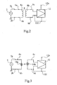
- the isolation input circuit 6 may be composed of a transformer 8 like the one shown in FIGURE 2 .
- the transformer 8 has a primary winding 8a and a secondary winding 8b.
- the two ends of the primary winding 8a are connected to the input terminals 6a and 6b, respectively, and the two ends of the secondary winding 8b are connected respectively to the output terminals 6c and 6d.
- Neither of the output terminals 6c and 6d is connected to the input terminal 6a or 6b. Accordingly, an audio signal is outputted between the output terminals 6c and 6d, being isolated from the primary winding 8a.
- the isolation input circuit 6 may be composed of a light-emitting device, e.g. a light-emitting diode 10a, and a light-receiving device, e.g. a photodiode 10b, as shown in FIGURE 3 .
- the light-emitting diode 10a has its two ends connected to the input terminals 6a and 6b, respectively, and emits light in response to the flow of the audio signal therethrough. The emitted light is received by the photodiode 10b connected between the output terminals 6c and 6d, causing current to flow therethrough. Neither of the output terminals 6c and 6d is connected to the input terminal 6a or 6b.
- an audio signal is outputted between the output terminals 6c and 6d, being isolated from the primary winding 8a.
- a bias circuit is actually provided for each of the light-emitting diode 10a and the photodiode 10b, they are not shown in FIGURE 3 since such is known.
- a photocoupler may be used as the light-emitting diode 10a and photodiode 10b.
- the audio signal developed between the two output terminals 6c and 6d of the isolation input circuit 6 is applied to two input terminals 12a and 12b of power amplifying means, e.g. a power amplifying stage 12.
- the power amplifying stage 12 is of an OTL configuration, which does not include an output transformer, for power amplification and develops a high output voltage between two output terminals 12c and 12d thereof.
- the output terminals 12c and 12d are also output terminals of the power amplifier 4, and the output terminal 12d is connected to the input terminal 12b.
- a power amplifying stage of various types may be used as the power amplifying stage 12.
- an analog power amplifying stage e.g. a Class AB or Class B power amplifying stage, may be used, or a Class D switching-type power amplifier may be used.
- the power amplifying stage 12 has power supply input terminals 12e and 12f.
- a DC power supply 14 is provided for supplying operating power to the power supply input terminals 12e and 12f.
- the DC power supply 14 has a transformer 16 for transforming commercial AC power.
- the commercial AC voltage is voltage-transformed, and the voltage-transformed commercial AC voltage is induced in the secondary side of the transformer 16.
- the induced commercial AC voltage is isolated from the ground potential, and is applied between two input terminals 18a and 18b of rectifying means, e.g. a rectifying bridge circuit 18, which results in a rectified voltage developed between two output terminals 18c and 18d.
- This rectified voltage is applied between two input terminals 20a and 20b of a smoothing circuit 20 including a plurality of smoothing capacitors and smoothing reactors, for example, so that a smoothed DC voltage is developed at a power supply terminal, or between two power supply output terminals 20c and 20d, for example.
- the power supply output terminal 20c of the smoothing circuit 20 is connected to the power supply input terminal 12e of the power amplifying stage 12, and the power supply output terminal 20d is connected to the power supply input terminal 12f, which, in turn, is connected to the output terminal 12d and the input terminal 12b.
- the smoothing circuit 20 and the power amplifying stage 12 operate on the output terminal 20d serving as a reference potential, and, thus, does not operate on the ground potential serving as a reference potential.
- a plurality of loudspeakers 22 are connected in parallel between the output terminals 12c and 12d of the power amplifying stage 12 via a pair of transmission lines 24.
- the loudspeakers 22 have their voice coils connected to the secondary sides of their matching transformers, and the primary sides of the matching transformers are connected together via the transmission lines 24. Since one of the terminals of the primary side of each matching transformer is connected to the output terminal 12d, each loudspeaker 22 operates on the power supply output terminal 20d of the smoothing circuit 20 serving as a reference potential and, thus, does not operate on the ground potential serving as a reference potential.
- the transmission lines 24, the power amplifying stage 12 and the smoothing circuit 20 of the public-address system with the above-described arrangement do not operate on the ground potential, and thus are isolated from the ground potential by the isolation input circuit 6 disposed in the input side of the power amplifying stage 12. Accordingly, even when the transmission lines 24 are struck by lightning, it does not occur that large current flows to the ground potential, so that a required breakdown resistance can be secured. In addition, since the securing of this breakdown-withstanding voltage is realized by the use of the isolation input circuit 6 disposed on the input side of the power amplifying stage 12, there is no need to use a transformer in the output side of the power amplifying stage 12, which makes it possible to downsize the power amplifier 4 using the power amplifying stage 12.
Landscapes
- Engineering & Computer Science (AREA)
- Power Engineering (AREA)
- Health & Medical Sciences (AREA)
- General Health & Medical Sciences (AREA)
- Otolaryngology (AREA)
- Physics & Mathematics (AREA)
- Acoustics & Sound (AREA)
- Signal Processing (AREA)
- Multimedia (AREA)
- Amplifiers (AREA)
- Circuit For Audible Band Transducer (AREA)
Applications Claiming Priority (2)
| Application Number | Priority Date | Filing Date | Title |
|---|---|---|---|
| JP2007237837A JP5139014B2 (ja) | 2007-09-13 | 2007-09-13 | 構内放送システム |
| PCT/JP2008/065851 WO2009034889A1 (ja) | 2007-09-13 | 2008-09-03 | 構内放送システム |
Publications (3)
| Publication Number | Publication Date |
|---|---|
| EP2190114A1 EP2190114A1 (en) | 2010-05-26 |
| EP2190114A4 EP2190114A4 (en) | 2012-05-09 |
| EP2190114B1 true EP2190114B1 (en) | 2014-08-13 |
Family
ID=40451898
Family Applications (1)
| Application Number | Title | Priority Date | Filing Date |
|---|---|---|---|
| EP08830079.3A Active EP2190114B1 (en) | 2007-09-13 | 2008-09-03 | Local broadcasting system |
Country Status (5)
| Country | Link |
|---|---|
| US (1) | US8306239B2 (enExample) |
| EP (1) | EP2190114B1 (enExample) |
| JP (1) | JP5139014B2 (enExample) |
| CN (1) | CN101803183B (enExample) |
| WO (1) | WO2009034889A1 (enExample) |
Families Citing this family (4)
| Publication number | Priority date | Publication date | Assignee | Title |
|---|---|---|---|---|
| JP5685173B2 (ja) * | 2011-10-04 | 2015-03-18 | Toa株式会社 | 拡声システム |
| CN102412741A (zh) * | 2011-12-12 | 2012-04-11 | 西安福安创意咨询有限责任公司 | 一种日光灯隔离型双电源方法 |
| CN102420536A (zh) * | 2011-12-12 | 2012-04-18 | 西安福安创意咨询有限责任公司 | 一种led隔离型双电源方法 |
| CN103780211A (zh) * | 2013-12-31 | 2014-05-07 | 北京长峰广播通讯设备有限责任公司 | 高电压固态放大器 |
Family Cites Families (10)
| Publication number | Priority date | Publication date | Assignee | Title |
|---|---|---|---|---|
| JPH03108907A (ja) * | 1989-09-22 | 1991-05-09 | Sharp Corp | 絶縁アンプ |
| JPH0467782A (ja) | 1990-07-06 | 1992-03-03 | Matoritsukusu:Kk | 交流電力増幅装置 |
| US5818328A (en) * | 1995-10-03 | 1998-10-06 | Audio Enhancement | Method and system for providing improved wireless audio transmission |
| JP3538534B2 (ja) * | 1997-12-19 | 2004-06-14 | ティーオーエー株式会社 | スピーカラインの検査装置 |
| US6407603B2 (en) * | 1999-09-20 | 2002-06-18 | Lockheed Martin Corporation | Analog voltage isolation circuit |
| JP2004112161A (ja) * | 2002-09-17 | 2004-04-08 | Sony Corp | 音声出力装置 |
| JP4053398B2 (ja) * | 2002-10-04 | 2008-02-27 | 松下電器産業株式会社 | パワードスピーカー装置 |
| JP2005236349A (ja) * | 2004-02-17 | 2005-09-02 | Toa Corp | 増幅器 |
| US20060182288A1 (en) * | 2005-02-16 | 2006-08-17 | Arcaria Angelo S | Addressable zone relay method and apparatus |
| JP4607742B2 (ja) * | 2005-11-15 | 2011-01-05 | アバゴ・テクノロジーズ・イーシービーユー・アイピー(シンガポール)プライベート・リミテッド | フォトカプラの制御装置及びフォトカプラの制御方法 |
-
2007
- 2007-09-13 JP JP2007237837A patent/JP5139014B2/ja active Active
-
2008
- 2008-09-03 US US12/677,593 patent/US8306239B2/en active Active
- 2008-09-03 EP EP08830079.3A patent/EP2190114B1/en active Active
- 2008-09-03 CN CN2008801065580A patent/CN101803183B/zh active Active
- 2008-09-03 WO PCT/JP2008/065851 patent/WO2009034889A1/ja not_active Ceased
Also Published As
| Publication number | Publication date |
|---|---|
| WO2009034889A1 (ja) | 2009-03-19 |
| JP2009071582A (ja) | 2009-04-02 |
| EP2190114A4 (en) | 2012-05-09 |
| JP5139014B2 (ja) | 2013-02-06 |
| US8306239B2 (en) | 2012-11-06 |
| CN101803183A (zh) | 2010-08-11 |
| US20100189278A1 (en) | 2010-07-29 |
| EP2190114A1 (en) | 2010-05-26 |
| CN101803183B (zh) | 2013-08-14 |
Similar Documents
| Publication | Publication Date | Title |
|---|---|---|
| NL8102999A (nl) | Microfoonuitgangstransmissieschakeling. | |
| TWI509986B (zh) | 聲訊放大器及將聲訊放大器變組態的方法 | |
| US20100171552A1 (en) | Push-Pull Linear Hybrid Class H Amplifier | |
| US8306239B2 (en) | Public-address system | |
| SE531023C2 (sv) | Ljudåtergivningssystem | |
| US10382852B2 (en) | Condenser microphone circuit | |
| KR20250101990A (ko) | 전관 방송시스템에서 출력 가변형 다단 트랜스포머를 구비한 다채널 앰프 | |
| EP2202880A1 (en) | Audio power amplifier | |
| KR101248181B1 (ko) | 전관방송 시스템용 출력 트랜스 내장형 d클래스 파워앰프 | |
| EP0913929A3 (en) | Audio output amplifier with parallel class AB stages | |
| US10178465B2 (en) | Headphone unit | |
| US7171011B2 (en) | Acoustic drive circuit | |
| US6437648B1 (en) | Audio amplifier with transformerless power supply | |
| EP0777403B1 (en) | A system of sound diffusion, particularly for large spaces | |
| JP2005236349A (ja) | 増幅器 | |
| US6674866B2 (en) | Audio reproduction apparatus | |
| EP2755322B1 (en) | An audio amplifier | |
| US20170164091A1 (en) | Electroacoustic Sound Transducer Unit and Earphone | |
| CN222235051U (zh) | 一种扬声器功率分配器 | |
| US9431970B1 (en) | Methods and apparatus for relatively invariant input-output spectral relationship amplifiers | |
| US20120224717A1 (en) | Audio cable capable of increasing gain and filtering noise | |
| JP3154994U (ja) | マイク用マッチングボックス | |
| EP1303163B1 (en) | Audio reproduction apparatus | |
| JP6533452B2 (ja) | マイクロホン電源回路 | |
| KR101253711B1 (ko) | 과부하를 방지할 수 있는 공동시설 방송용 증폭장치 |
Legal Events
| Date | Code | Title | Description |
|---|---|---|---|
| PUAI | Public reference made under article 153(3) epc to a published international application that has entered the european phase |
Free format text: ORIGINAL CODE: 0009012 |
|
| 17P | Request for examination filed |
Effective date: 20100311 |
|
| AK | Designated contracting states |
Kind code of ref document: A1 Designated state(s): AT BE BG CH CY CZ DE DK EE ES FI FR GB GR HR HU IE IS IT LI LT LU LV MC MT NL NO PL PT RO SE SI SK TR |
|
| AX | Request for extension of the european patent |
Extension state: AL BA MK RS |
|
| DAX | Request for extension of the european patent (deleted) | ||
| A4 | Supplementary search report drawn up and despatched |
Effective date: 20120412 |
|
| RIC1 | Information provided on ipc code assigned before grant |
Ipc: H03F 1/52 20060101ALI20120404BHEP Ipc: H03F 3/20 20060101AFI20120404BHEP Ipc: H04R 3/00 20060101ALI20120404BHEP Ipc: H04R 3/12 20060101ALI20120404BHEP |
|
| 17Q | First examination report despatched |
Effective date: 20121212 |
|
| GRAP | Despatch of communication of intention to grant a patent |
Free format text: ORIGINAL CODE: EPIDOSNIGR1 |
|
| INTG | Intention to grant announced |
Effective date: 20140218 |
|
| GRAS | Grant fee paid |
Free format text: ORIGINAL CODE: EPIDOSNIGR3 |
|
| GRAP | Despatch of communication of intention to grant a patent |
Free format text: ORIGINAL CODE: EPIDOSNIGR1 |
|
| GRAA | (expected) grant |
Free format text: ORIGINAL CODE: 0009210 |
|
| INTG | Intention to grant announced |
Effective date: 20140626 |
|
| AK | Designated contracting states |
Kind code of ref document: B1 Designated state(s): AT BE BG CH CY CZ DE DK EE ES FI FR GB GR HR HU IE IS IT LI LT LU LV MC MT NL NO PL PT RO SE SI SK TR |
|
| REG | Reference to a national code |
Ref country code: GB Ref legal event code: FG4D |
|
| REG | Reference to a national code |
Ref country code: CH Ref legal event code: EP Ref country code: AT Ref legal event code: REF Ref document number: 682732 Country of ref document: AT Kind code of ref document: T Effective date: 20140815 |
|
| REG | Reference to a national code |
Ref country code: IE Ref legal event code: FG4D |
|
| REG | Reference to a national code |
Ref country code: DE Ref legal event code: R096 Ref document number: 602008033873 Country of ref document: DE Effective date: 20140925 |
|
| REG | Reference to a national code |
Ref country code: NL Ref legal event code: VDEP Effective date: 20140813 |
|
| REG | Reference to a national code |
Ref country code: AT Ref legal event code: MK05 Ref document number: 682732 Country of ref document: AT Kind code of ref document: T Effective date: 20140813 |
|
| REG | Reference to a national code |
Ref country code: LT Ref legal event code: MG4D |
|
| PG25 | Lapsed in a contracting state [announced via postgrant information from national office to epo] |
Ref country code: BG Free format text: LAPSE BECAUSE OF FAILURE TO SUBMIT A TRANSLATION OF THE DESCRIPTION OR TO PAY THE FEE WITHIN THE PRESCRIBED TIME-LIMIT Effective date: 20141113 Ref country code: FI Free format text: LAPSE BECAUSE OF FAILURE TO SUBMIT A TRANSLATION OF THE DESCRIPTION OR TO PAY THE FEE WITHIN THE PRESCRIBED TIME-LIMIT Effective date: 20140813 Ref country code: GR Free format text: LAPSE BECAUSE OF FAILURE TO SUBMIT A TRANSLATION OF THE DESCRIPTION OR TO PAY THE FEE WITHIN THE PRESCRIBED TIME-LIMIT Effective date: 20141114 Ref country code: SE Free format text: LAPSE BECAUSE OF FAILURE TO SUBMIT A TRANSLATION OF THE DESCRIPTION OR TO PAY THE FEE WITHIN THE PRESCRIBED TIME-LIMIT Effective date: 20140813 Ref country code: ES Free format text: LAPSE BECAUSE OF FAILURE TO SUBMIT A TRANSLATION OF THE DESCRIPTION OR TO PAY THE FEE WITHIN THE PRESCRIBED TIME-LIMIT Effective date: 20140813 Ref country code: LT Free format text: LAPSE BECAUSE OF FAILURE TO SUBMIT A TRANSLATION OF THE DESCRIPTION OR TO PAY THE FEE WITHIN THE PRESCRIBED TIME-LIMIT Effective date: 20140813 Ref country code: NO Free format text: LAPSE BECAUSE OF FAILURE TO SUBMIT A TRANSLATION OF THE DESCRIPTION OR TO PAY THE FEE WITHIN THE PRESCRIBED TIME-LIMIT Effective date: 20141113 Ref country code: PT Free format text: LAPSE BECAUSE OF FAILURE TO SUBMIT A TRANSLATION OF THE DESCRIPTION OR TO PAY THE FEE WITHIN THE PRESCRIBED TIME-LIMIT Effective date: 20141215 |
|
| PG25 | Lapsed in a contracting state [announced via postgrant information from national office to epo] |
Ref country code: LV Free format text: LAPSE BECAUSE OF FAILURE TO SUBMIT A TRANSLATION OF THE DESCRIPTION OR TO PAY THE FEE WITHIN THE PRESCRIBED TIME-LIMIT Effective date: 20140813 Ref country code: CY Free format text: LAPSE BECAUSE OF FAILURE TO SUBMIT A TRANSLATION OF THE DESCRIPTION OR TO PAY THE FEE WITHIN THE PRESCRIBED TIME-LIMIT Effective date: 20140813 Ref country code: HR Free format text: LAPSE BECAUSE OF FAILURE TO SUBMIT A TRANSLATION OF THE DESCRIPTION OR TO PAY THE FEE WITHIN THE PRESCRIBED TIME-LIMIT Effective date: 20140813 Ref country code: IS Free format text: LAPSE BECAUSE OF FAILURE TO SUBMIT A TRANSLATION OF THE DESCRIPTION OR TO PAY THE FEE WITHIN THE PRESCRIBED TIME-LIMIT Effective date: 20141213 Ref country code: AT Free format text: LAPSE BECAUSE OF FAILURE TO SUBMIT A TRANSLATION OF THE DESCRIPTION OR TO PAY THE FEE WITHIN THE PRESCRIBED TIME-LIMIT Effective date: 20140813 |
|
| REG | Reference to a national code |
Ref country code: DE Ref legal event code: R082 Ref document number: 602008033873 Country of ref document: DE Representative=s name: PATENTANWAELTE LIPPERT, STACHOW & PARTNER, DE Ref country code: DE Ref legal event code: R082 Ref document number: 602008033873 Country of ref document: DE Representative=s name: LIPPERT STACHOW PATENTANWAELTE RECHTSANWAELTE , DE |
|
| PG25 | Lapsed in a contracting state [announced via postgrant information from national office to epo] |
Ref country code: NL Free format text: LAPSE BECAUSE OF FAILURE TO SUBMIT A TRANSLATION OF THE DESCRIPTION OR TO PAY THE FEE WITHIN THE PRESCRIBED TIME-LIMIT Effective date: 20140813 |
|
| PG25 | Lapsed in a contracting state [announced via postgrant information from national office to epo] |
Ref country code: DK Free format text: LAPSE BECAUSE OF FAILURE TO SUBMIT A TRANSLATION OF THE DESCRIPTION OR TO PAY THE FEE WITHIN THE PRESCRIBED TIME-LIMIT Effective date: 20140813 Ref country code: EE Free format text: LAPSE BECAUSE OF FAILURE TO SUBMIT A TRANSLATION OF THE DESCRIPTION OR TO PAY THE FEE WITHIN THE PRESCRIBED TIME-LIMIT Effective date: 20140813 Ref country code: SK Free format text: LAPSE BECAUSE OF FAILURE TO SUBMIT A TRANSLATION OF THE DESCRIPTION OR TO PAY THE FEE WITHIN THE PRESCRIBED TIME-LIMIT Effective date: 20140813 Ref country code: RO Free format text: LAPSE BECAUSE OF FAILURE TO SUBMIT A TRANSLATION OF THE DESCRIPTION OR TO PAY THE FEE WITHIN THE PRESCRIBED TIME-LIMIT Effective date: 20140813 Ref country code: CZ Free format text: LAPSE BECAUSE OF FAILURE TO SUBMIT A TRANSLATION OF THE DESCRIPTION OR TO PAY THE FEE WITHIN THE PRESCRIBED TIME-LIMIT Effective date: 20140813 |
|
| REG | Reference to a national code |
Ref country code: CH Ref legal event code: PL |
|
| REG | Reference to a national code |
Ref country code: DE Ref legal event code: R097 Ref document number: 602008033873 Country of ref document: DE |
|
| PG25 | Lapsed in a contracting state [announced via postgrant information from national office to epo] |
Ref country code: MC Free format text: LAPSE BECAUSE OF FAILURE TO SUBMIT A TRANSLATION OF THE DESCRIPTION OR TO PAY THE FEE WITHIN THE PRESCRIBED TIME-LIMIT Effective date: 20140813 Ref country code: PL Free format text: LAPSE BECAUSE OF FAILURE TO SUBMIT A TRANSLATION OF THE DESCRIPTION OR TO PAY THE FEE WITHIN THE PRESCRIBED TIME-LIMIT Effective date: 20140813 |
|
| REG | Reference to a national code |
Ref country code: IE Ref legal event code: MM4A |
|
| PLBE | No opposition filed within time limit |
Free format text: ORIGINAL CODE: 0009261 |
|
| STAA | Information on the status of an ep patent application or granted ep patent |
Free format text: STATUS: NO OPPOSITION FILED WITHIN TIME LIMIT |
|
| PG25 | Lapsed in a contracting state [announced via postgrant information from national office to epo] |
Ref country code: BE Free format text: LAPSE BECAUSE OF NON-PAYMENT OF DUE FEES Effective date: 20140930 |
|
| 26N | No opposition filed |
Effective date: 20150515 |
|
| PG25 | Lapsed in a contracting state [announced via postgrant information from national office to epo] |
Ref country code: LI Free format text: LAPSE BECAUSE OF NON-PAYMENT OF DUE FEES Effective date: 20140930 Ref country code: CH Free format text: LAPSE BECAUSE OF NON-PAYMENT OF DUE FEES Effective date: 20140930 |
|
| PG25 | Lapsed in a contracting state [announced via postgrant information from national office to epo] |
Ref country code: IE Free format text: LAPSE BECAUSE OF NON-PAYMENT OF DUE FEES Effective date: 20140903 |
|
| PG25 | Lapsed in a contracting state [announced via postgrant information from national office to epo] |
Ref country code: SI Free format text: LAPSE BECAUSE OF FAILURE TO SUBMIT A TRANSLATION OF THE DESCRIPTION OR TO PAY THE FEE WITHIN THE PRESCRIBED TIME-LIMIT Effective date: 20140813 |
|
| PG25 | Lapsed in a contracting state [announced via postgrant information from national office to epo] |
Ref country code: MT Free format text: LAPSE BECAUSE OF FAILURE TO SUBMIT A TRANSLATION OF THE DESCRIPTION OR TO PAY THE FEE WITHIN THE PRESCRIBED TIME-LIMIT Effective date: 20140813 |
|
| PG25 | Lapsed in a contracting state [announced via postgrant information from national office to epo] |
Ref country code: BE Free format text: LAPSE BECAUSE OF FAILURE TO SUBMIT A TRANSLATION OF THE DESCRIPTION OR TO PAY THE FEE WITHIN THE PRESCRIBED TIME-LIMIT Effective date: 20140813 Ref country code: HU Free format text: LAPSE BECAUSE OF FAILURE TO SUBMIT A TRANSLATION OF THE DESCRIPTION OR TO PAY THE FEE WITHIN THE PRESCRIBED TIME-LIMIT; INVALID AB INITIO Effective date: 20080903 Ref country code: TR Free format text: LAPSE BECAUSE OF FAILURE TO SUBMIT A TRANSLATION OF THE DESCRIPTION OR TO PAY THE FEE WITHIN THE PRESCRIBED TIME-LIMIT Effective date: 20140813 Ref country code: LU Free format text: LAPSE BECAUSE OF NON-PAYMENT OF DUE FEES Effective date: 20140903 |
|
| REG | Reference to a national code |
Ref country code: FR Ref legal event code: PLFP Year of fee payment: 9 |
|
| REG | Reference to a national code |
Ref country code: FR Ref legal event code: PLFP Year of fee payment: 10 |
|
| REG | Reference to a national code |
Ref country code: FR Ref legal event code: PLFP Year of fee payment: 11 |
|
| PGFP | Annual fee paid to national office [announced via postgrant information from national office to epo] |
Ref country code: DE Payment date: 20250902 Year of fee payment: 18 |
|
| PGFP | Annual fee paid to national office [announced via postgrant information from national office to epo] |
Ref country code: IT Payment date: 20250922 Year of fee payment: 18 |
|
| PGFP | Annual fee paid to national office [announced via postgrant information from national office to epo] |
Ref country code: GB Payment date: 20250828 Year of fee payment: 18 |
|
| PGFP | Annual fee paid to national office [announced via postgrant information from national office to epo] |
Ref country code: FR Payment date: 20250908 Year of fee payment: 18 |