EP2189702A1 - Dispositif de transport de fluide notamment pour carburant - Google Patents
Dispositif de transport de fluide notamment pour carburant Download PDFInfo
- Publication number
- EP2189702A1 EP2189702A1 EP09290839A EP09290839A EP2189702A1 EP 2189702 A1 EP2189702 A1 EP 2189702A1 EP 09290839 A EP09290839 A EP 09290839A EP 09290839 A EP09290839 A EP 09290839A EP 2189702 A1 EP2189702 A1 EP 2189702A1
- Authority
- EP
- European Patent Office
- Prior art keywords
- conductive
- resistance
- section
- end section
- useful
- Prior art date
- Legal status (The legal status is an assumption and is not a legal conclusion. Google has not performed a legal analysis and makes no representation as to the accuracy of the status listed.)
- Granted
Links
Images

Classifications
-
- F—MECHANICAL ENGINEERING; LIGHTING; HEATING; WEAPONS; BLASTING
- F16—ENGINEERING ELEMENTS AND UNITS; GENERAL MEASURES FOR PRODUCING AND MAINTAINING EFFECTIVE FUNCTIONING OF MACHINES OR INSTALLATIONS; THERMAL INSULATION IN GENERAL
- F16L—PIPES; JOINTS OR FITTINGS FOR PIPES; SUPPORTS FOR PIPES, CABLES OR PROTECTIVE TUBING; MEANS FOR THERMAL INSULATION IN GENERAL
- F16L25/00—Construction or details of pipe joints not provided for in, or of interest apart from, groups F16L13/00 - F16L23/00
- F16L25/01—Construction or details of pipe joints not provided for in, or of interest apart from, groups F16L13/00 - F16L23/00 specially adapted for realising electrical conduction between the two pipe ends of the joint or between parts thereof
-
- A—HUMAN NECESSITIES
- A62—LIFE-SAVING; FIRE-FIGHTING
- A62C—FIRE-FIGHTING
- A62C3/00—Fire prevention, containment or extinguishing specially adapted for particular objects or places
- A62C3/07—Fire prevention, containment or extinguishing specially adapted for particular objects or places in vehicles, e.g. in road vehicles
- A62C3/08—Fire prevention, containment or extinguishing specially adapted for particular objects or places in vehicles, e.g. in road vehicles in aircraft
-
- B—PERFORMING OPERATIONS; TRANSPORTING
- B64—AIRCRAFT; AVIATION; COSMONAUTICS
- B64D—EQUIPMENT FOR FITTING IN OR TO AIRCRAFT; FLIGHT SUITS; PARACHUTES; ARRANGEMENT OR MOUNTING OF POWER PLANTS OR PROPULSION TRANSMISSIONS IN AIRCRAFT
- B64D37/00—Arrangements in connection with fuel supply for power plant
- B64D37/32—Safety measures not otherwise provided for, e.g. preventing explosive conditions
-
- F—MECHANICAL ENGINEERING; LIGHTING; HEATING; WEAPONS; BLASTING
- F16—ENGINEERING ELEMENTS AND UNITS; GENERAL MEASURES FOR PRODUCING AND MAINTAINING EFFECTIVE FUNCTIONING OF MACHINES OR INSTALLATIONS; THERMAL INSULATION IN GENERAL
- F16L—PIPES; JOINTS OR FITTINGS FOR PIPES; SUPPORTS FOR PIPES, CABLES OR PROTECTIVE TUBING; MEANS FOR THERMAL INSULATION IN GENERAL
- F16L25/00—Construction or details of pipe joints not provided for in, or of interest apart from, groups F16L13/00 - F16L23/00
- F16L25/02—Construction or details of pipe joints not provided for in, or of interest apart from, groups F16L13/00 - F16L23/00 specially adapted for electrically insulating the two pipe ends of the joint from each other
-
- Y—GENERAL TAGGING OF NEW TECHNOLOGICAL DEVELOPMENTS; GENERAL TAGGING OF CROSS-SECTIONAL TECHNOLOGIES SPANNING OVER SEVERAL SECTIONS OF THE IPC; TECHNICAL SUBJECTS COVERED BY FORMER USPC CROSS-REFERENCE ART COLLECTIONS [XRACs] AND DIGESTS
- Y02—TECHNOLOGIES OR APPLICATIONS FOR MITIGATION OR ADAPTATION AGAINST CLIMATE CHANGE
- Y02T—CLIMATE CHANGE MITIGATION TECHNOLOGIES RELATED TO TRANSPORTATION
- Y02T50/00—Aeronautics or air transport
- Y02T50/40—Weight reduction
Definitions
- the present invention relates to a fluid transport device, especially for fuel in an aeronautical application.
- the aircraft wings are most often made in the form of a non-electrically insulating composite material structure and electrically conductive stiffening elements generally made of aluminum.
- the fuel pipes located inside the wings of aircraft must allow on the one hand to discharge the electrostatic charges and on the other hand to avoid a short circuit of the structure in case of lightning.
- the material that constitutes the central section is an epoxy resin filled with glass fibers and carbon black, which implies a relatively high weight.
- the present invention thus aims to provide the desired function while decreasing the weight and possibly the cost of the tube.
- the device has two end sections having a useful resistor of between 100 k ⁇ and 500 k ⁇ and two said conductive elements each connecting an end section to the corresponding conductive tip.
- At least one end section may include an extension of the central section which is successively surrounded by a conductive sleeve and an end fitting.
- At least one conductive element may be a conductive wire or a conductive seal.
- the device is characterized in that it has two end sections having a useful resistance of between 100 k ⁇ and 500 k ⁇ and at least one said conductive element disposed on a only end section and connecting it to the corresponding conductive endpiece.
- the device is characterized in that it has a first end section having a resistance of between 100 k ⁇ and 500 k ⁇ and a second end section having a useful resistance. less than this value and at least one said conductive element disposed on the second end section and connecting it to the corresponding conductive tip.
- the central section may be made of a thermoplastic, thermosetting or elastomeric material with conductive fillers that serve both as mechanical reinforcement and to adjust the conductivity.
- At least one end section may be of a glass fiber filled material and conductive fillers.
- At least one end fitting may be of a thermoplastic or thermosetting material with possibly conductive fillers.
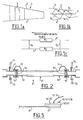
- FIG. 1a is a diagrammatic sectional view of an aircraft wing portion 1 which comprises a structure 2 made of composite material having a linear resistance of 10 3 ⁇ / m and stiffening elements 3 made of a conducting material such as aluminum.
- One or more fuel transport tubes 5 ( figure 1b ) are integral at their ends with two structural elements 3 1 and 3 2 .
- the tube shown in figure 2 has a central section 51 for example epoxy resin filled with glass fibers and carbon black, which has a resistivity of between 10 5 and 10 6 ⁇ .m.
- the resistivity being high, it is indeed a load of glass fibers, which imposes a relatively high thickness to ensure the mechanical properties.
- the end sections 52 and 53 are made of conductive material, for example at A1, and are extended by conductive end connectors 54 and 55. Conductive wires 13 and 14 make it possible to electrically connect the end sections 52 and 53 and the conductive connectors 11 and 12 which are traversed by the fuel. Sealing is provided by electrically insulating joints 15 and 16.
- the conductor patches 11 and 12 are fixed on the 3 elements of Structure 1 and 3 2.
- a tube 6 whose length is for example between 0.2 m and 1.2 m, has a central section 61 of conductive material whose linear resistance is less than 10 4 ⁇ / m, while the end sections have a useful resistor of between 100 k ⁇ and 500 k ⁇ , the useful resistor being defined as the resistor R 3 or R 4 of the end section 62 or 63 and, if appropriate, of the connection 64, 65, 64 'or 65' between the central section 61 and point 13 'and 14' where the wire 13 or 14 makes contact with the end section 62 or 63 extended by a conductive or insulating end connection 64 or 65.
- An end connection 64 and / or 65 may be made of a glued or welded thermoplastic material (for example polyamide, PEEK, PEI) optionally loaded with fibers, especially carbon fibers, to reinforce it and regulate its conductivity, or else a thermosetting material whose conductivity may be adjusted by means of fibers carbon or aut conductive rests such as graphite or nanoparticles.
- the central section 61 is for example a thermosetting material, or elastomer with conductive fillers to strengthen and adjust its conductivity, is for example epoxy resin or polyamide loaded with conductive fillers including carbon fibers. In the central section 61, which occupies about 80% to 95% of the length of the tube 6, the presence of glass fibers is thus avoided. Preferably, it has only conductive fillers.
- the end sections 62 and 63 are made of a material, for example a polyamide, filled with glass fibers, and conductive fillers, for example carbon black.
- the figure 3b illustrates another embodiment that differs from the figure 3a by the presence of conductive seals 17 and 18 in place of the son 13 and 14. In this case, the entire length of the end sections 62 and 63 is taken into account to define the resistors R 3 and R 4 .
- the central section 61 has a low resistance, it is possible to reduce its weight, it is not necessary to add glass fibers (the carbon fibers are sufficient), so that its thickness can be reduced. while satisfying the required mechanical properties, resulting in a weight gain of, for example, 20% to 30%. Since the end sections 62 and 63 are not made of metal, a gain in weight generally greater than 15% is obtained.
- the central section 61 may comprise long carbon fibers in a thermoplastic material, carbon fibers in a thermosetting material, for example an epoxy resin, or a filled thermoplastic or a conductive rubber loaded with a conductive filler, for example carbon fibers. short (length ⁇ 1mm).
- the central section 61 has a lower resistance than in the prior art is favorable to the evacuation of charges, while in case of lightning, the tube 6 which has a significantly higher electrical resistance than the structure 2 avoids a short circuit.
- the contact is made only on one side by one or two son 14 and 14 '.
- the end section 63 it is possible for the end section 63 to be made of a more conductive material than the other end section 61, for example the same material as the central section 62.
- the figure 5 is a variant in which the end sections 62 and 63 are constituted by an extension of the central section 61 which is surrounded by a resistive sleeve 62 'or 63', itself surrounded by an end connection 64 'or 65 .
- the resistive sleeve may be a resistive glue or a rubber or a thermoplastic filled with glass fibers.
- the end fitting 64 'or 65 may be conductive (for example metal) or resistive.
- the contacting by the wire 13, 14 is effected by the end connection 64 'or 65'.
- the value of its resistance is to be taken into account for the calculation of the useful resistance.
Landscapes
- Engineering & Computer Science (AREA)
- General Engineering & Computer Science (AREA)
- Mechanical Engineering (AREA)
- Public Health (AREA)
- Business, Economics & Management (AREA)
- Emergency Management (AREA)
- Health & Medical Sciences (AREA)
- Aviation & Aerospace Engineering (AREA)
- Rigid Pipes And Flexible Pipes (AREA)
- Compositions Of Macromolecular Compounds (AREA)
- Gasket Seals (AREA)
- Conductive Materials (AREA)
- Laminated Bodies (AREA)
- Control Of The Air-Fuel Ratio Of Carburetors (AREA)
Abstract
Description
- La présente invention a pour objet un dispositif de transport de fluide, notamment pour carburant dans une application aéronautique.
- Les ailes d'avion sont le plus souvent réalisées sous forme d'une structure en matériau composite non électriquement isolant et d'éléments de rigidification électriquement conducteurs généralement en aluminium.
- Les tuyaux de carburant situés à l'intérieur des ailes d'avion doivent permettre d'une part de décharger les charges électrostatiques et d'autre part d'éviter un court-circuit de la structure en cas de foudre.
- Il est connu de concevoir des tubes ayant une section centrale en matériau ayant une résistivité élevée et deux sections d'extrémité en matériau conducteur qui sont connectées par des fils conducteurs à des embouts conducteurs dont chacun est solidaire d'un élément de rigidification.
- Le matériau qui constitue la section centrale est une résine epoxy chargée de fibres de verre et de noir de carbone, ce qui implique un poids relativement élevé.
- La présente invention a ainsi pour objet d'assurer la fonction recherchée tout en diminuant le poids et éventuellement le coût du tube.
- Dans ce but, l'invention a pour objet un dispositif de transport de fluide destiné à être incorporé à une structure non électriquemement isolante, notamment en composite et comportant un tube électriquement résistant, et des embouts conducteurs comprenant un moyen de fixation sur ladite structure, caractérisé en ce que le tube comporte :
- une section centrale ayant une résistance inférieure à 104 Ω par mètre de longueur
- deux sections d'extrémités dont au moins une présente une résistance utile comprise entre 100 kΩ et 500 kΩ, qui se terminent par un raccord d'extrémité
- Selon une première variante, le dispositif présente deux sections d'extrémité présentant une résistance utile comprise entre 100 kΩet 500 kΩ et deux dits éléments conducteurs reliant chacun une section d'extrémité à l'embout conducteur correspondant.
- Au moins une section d'extrémité peut comporter un prolongement de la section centrale qui est entouré successivement d'un manchon conducteur et d'un raccord d'extrémité.
- Au moins un élément conducteur peut être un fil conducteur ou un joint conducteur.
- Selon un premier mode de mise en oeuvre d'une deuxième variante, le dispositif est caractérisé en ce qu'il présente deux sections d'extrémité présentant une résistance utile comprise entre 100 kΩ et 500 kΩ et au moins un dit élément conducteur disposé sur une seule section d'extrémité et reliant celle-ci à l'embout conducteur correspondant.
- Selon un deuxième mode de mise en oeuvre de la deuxième variante, le dispositif est caractérisé en ce qu'il présente une première section d'extrémité présentant une résistance comprise entre 100 kΩ et 500 kΩ et une deuxième section d'extrémité présentant une résistance utile inférieure à cette valeur et au moins un dit élément conducteur disposé sur la deuxième section d'extrémité et reliant celle-ci à l'embout conducteur correspondant.
- La section centrale peut être en un matériau thermoplastique, thermodurcissable ou élastomère avec des charges conductrices qui servent à la fois de renfort mécanique et à ajuster la conductivité.
- Au moins une section d'extrémité peut être en un matériau chargé de fibres de verre et de charges conductrices.
- Au moins un raccord d'extrémité peut être en un matériau thermoplastique ou thermodurcissable avec éventuellement des charges conductrices.
- L'invention sera mieux comprise à la lecture de la description ci-après, en liaison avec les dessins dans lesquels :
- les figures la et 1b sont une illustration schématique d'une structure d'aile d'avion, et la
figure 1c un schéma électrique équivalent pour un tuyau de carburant ; - la
figure 2 représente un tube selon l'art antérieur ; - les
figures 3a et 3b représentent deux modes de mise en oeuvre d'une première variante de l'invention ; - la
figure 4 représente une deuxième variante de l'invention ; - et la
figure 5 illustre une variante de montage des raccords d'extrémité. - La figure la est une vue schématique en coupe d'une portion d'aile d'avion 1 qui comporte une structure 2 en matériau composite ayant une résistances linéique de 103 Ω/m et des éléments de rigidification 3 en matériau conducteur tel que l'aluminium. Un ou plusieurs tubes 5 de transport de carburant (
figure 1b ) sont solidaires à leurs extrémités de deux éléments de structure 31 et 32. - Un schéma électrique est donné à la
figure 1c . On suppose que la résistance équivalente de la structure est R1 = 103 Ω. - Le tube 5 pour remplir cette fonction doit avoir une résistance très supérieure à cette valeur, par exemple R2 = 105 Ω.
- Le tube représenté à la
figure 2 présente une section centrale 51 par exemple en résine epoxy chargée de fibres de verre et de noir de carbone, qui a une résistivité comprise entre 105 et 106 Ω.m. La résistivité étant élevée, il faut en effet une charge en fibres de verre, ce qui impose une épaisseur relativement élevée pour assurer les propriétés mécaniques. Les sections d'extrémité 52 et 53 sont en matériau conducteur par exemple en A1 et sont prolongées par des raccords d'extrémité conducteurs 54 et 55. Des fils conducteurs 13 et 14 permettent de relier électriquement les sections d'extrémité 52 et 53 et les raccords conducteurs 11 et 12 qui sont traversés par le carburant. L'étanchéité est assurée par des joints électriquement isolants 15 et 16. Les raccords conducteurs 11 et 12 sont fixés sur des éléments de structure 31 et 32. - La première variante de l'invention est représentée aux
figures 3a et 3b . Un tube 6 dont la longueur est par exemple comprise entre 0,2 m et 1,2 m, présente un tronçon central 61 en matériau conducteur dont la résistance linéique est inférieure à 104 Ω/m, alors que les tronçons d'extrémité ont une résistance utile comprise entre 100 kΩ et 500 kΩ, la résistance utile étant définie comme la résistance R3 ou R4 de la section d'extrémité 62 ou 63 et le cas échéant du raccord 64, 65, 64' ou 65' entre le tronçon central 61 et le point 13' et 14' où le fil 13 ou 14 fait contact avec le tronçon d'extrémité 62 ou 63 prolongé par un raccord d'extrémité conducteur ou isolant 64 ou 65. Un raccord d'extrémité 64 et/ou 65 peut être en un matériau thermoplastique collé ou soudé (par exemple polyamide, PEEK, PEI) éventuellement chargé de fibres notamment de carbone pour le renforcer et régler sa conductivité, ou bien en un matériau thermodurcissable dont on ajuste éventuellement la conductivité par des fibres de carbone ou d'autres charges conductrices telles que graphite ou des nano-particules. Le tronçon central 61 est par exemple en un matériau thermodurcissable, ou élastomère avec des charges conductrices pour le renforcer et ajuster sa conductivité, est par exemple en résine époxy ou en polyamide chargé de charges conductrices notamment des fibres de carbone. On évite ainsi dans le tronçon central 61, qui occupe environ 80% à 95% de la longueur du tube 6, la présence de fibres de verre. De préférence, il présente seulement des charges conductrices. - Par exemple, les sections d'extrémité 62 et 63 sont en un matériau, par exemple un polyamide, chargé de fibres de verre, et de charges conductrices par exemple du noir de carbone.
- La
figure 3b illustre un autre mode de réalisation qui diffère de lafigure 3a par la présence de joints conducteurs 17 et 18 en lieu et place des fils 13 et 14. Dans ce cas, toute la longueur des tronçons d'extrémité 62 et 63 est prise en compte pour définir les résistances R3 et R4. - Du fait que le tronçon central 61 a une faible résistance, il est possible de diminuer son poids, il n'est pas besoin d'ajouter des fibres de verre (les fibres de carbone suffisent), ce qui fait que son épaisseur peut être réduite tout en satisfaisant aux propriétés mécaniques requises, d'où un gain de masse par exemple de 20% à 30%. Du fait que les tronçons d'extrémité 62 et 63 ne sont pas en métal, on obtient un gain de poids en général supérieur à 15%.
- Le tronçon central 61 peut comporter des fibres longues de carbone dans un matériau thermoplastique, des fibres de carbone dans un matériau thermodurcissable par exemple une résine époxy, ou bien en thermoplastique chargé ou en caoutchouc conducteur chargé avec comme charge conductrice par exemple des fibres de carbone courtes (longueur < 1mm).
- Le fait que le tronçon central 61 ait une plus faible résistance que dans l'art antérieur est favorable à l'évacuation des charges, alors qu'en cas de foudre, le tube 6 qui présente une résistance électrique notablement supérieure à celle de la structure 2 évite une mise en court circuit.
- Dans la variante de la
figure 4 , la prise de contact est réalisée seulement d'un côté par un ou deux fils 14 et 14'. - Dans ce cas, il est possible que le tronçon d'extrémité 63 soit en matériau plus conducteur que l'autre tronçon d'extrémité 61, par exemple le même matériau que le tronçon central 62.
- Dans cette configuration, l'évacuation des charges électrostatique s'effectue par la liaison électrique 14 et/ou 14' et l'isolation contre la foudre est assurée par le fait que l'impédance entre les raccords 11 et 12 est infinie, car le joint 15 est électriquement isolant.
- La
figure 5 est une variante dans laquelle les tronçons d'extrémité 62 et 63 sont constitués par un prolongement du tronçon central 61 qui est entouré par un manchon résistif 62' ou 63', lui-même entouré d'un raccord d'extrémité 64' ou 65'. Le manchon résistif est peut être en une colle résistive ou bien encore en un caoutchouc ou en un thermoplastique chargé de fibres de verre. Le raccord d'extrémité 64' ou 65 peut être conducteur (par exemple en métal) ou résistif. - La prise de contact par le fil 13, 14 (ou par joint conducteur) s'effectue par le raccord d'extrémité 64' ou 65'. Dans le cas où celui-ci est résistif, la valeur de sa résistance est à prendre en compte pour le calcul de la résistance utile.
la dite résistance utile étant définie comme la valeur de la résistance de la section d'extrémité entre la section centrale et l'élément conducteur.
Claims (10)
- Dispositif de transport de fluide destiné à être incorporé à une structure non électriquemement isolante, notamment en composite et comportant un tube électriquement résistant, et des embouts conducteurs comprenant un moyen de fixation sur ladite structure, caractérisé en ce que le tube comporte :- une section centrale (61) ayant une résistance inférieure à 104 Ω par mètre de longueur- deux sections d'extrémités (62, 63) dont au moins une présente une résistance utile comprise entre 100 kΩ et 500 kΩ qui se terminent par un raccord d'extrémité (64, 65)et au moins un élément conducteur (13, 14, 14', 17, 18) reliant électriquement une section d'extrémité ayant une dite résistance utile comprise entre 100 kΩ et 500 kΩ, et un embout conducteur, la dite résistance utile étant définie comme la valeur de la résistance de la section d'extrémité entre la section centrale et l'élément conducteur.
- Dispositif selon la revendication 1, caractérisé en ce qu'il présente deux sections d'extrémité (62, 63) présentant une résistance utile comprise entre 100 kΩ et 500 kΩ et deux dits éléments conducteurs (13, 14, 17, 18) reliant chacun une section d'extrémité à l'embout conducteur correspondant (11, 12).
- Dispositif selon une des revendications 1 ou 2, caractérisé en ce qu'au moins un élément conducteur est un fil conducteur (13, 14).
- Dispositif selon une des revendications 1 à 3, caractérisé en ce qu'au moins un élément conducteur est un joint conducteur (17, 18).
- Dispositif selon la revendication 1, caractérisé en ce qu'il présente deux sections d'extrémité (62, 63) présentant une résistance utile comprise entre 100 kΩ et 500 kΩ et au moins un dit élément conducteur (14, 14') disposé sur une seule section d'extrémité (63) et reliant celle-ci à l'embout conducteur correspondant.
- Dispositif selon la revendication 1, caractérisé en ce qu'il présente une première section d'extrémité (62) présentant une résistance comprise entre 100 kΩ et 500 kΩ et une deuxième section d'extrémité (63) présentant une résistance utile inférieure à cette valeur et au moins un dit élément conducteur (14, 14') disposé sur la deuxième section d'extrémité (63) et reliant celle-ci à l'embout conducteur correspondant (12).
- Dispositif selon une des revendications précédentes, caractérisé en ce que la section centrale (61) est en un matériau thermoplastique, thermodurcissable ou élastomère avec des charges conductrices.
- Dispositif selon une des revendications précédentes, caractérisé en ce qu'au moins une section d'extrémité (62, 63) est en un matériau chargé par des fibres de verre et des charges conductrices.
- Dispositif selon une des revendications précédentes, caractérisé en ce qu'au moins un raccord d'extrémité (64, 65) est en un matériau thermoplastique ou thermodurcissable avec éventuellement des charges conductrices.
- Dispositif selon une des revendications précédentes, caractérisé en ce qu'au moins une section d'extrémité (62, 63) comporte un prolongement (61') de la section centrale (61) qui est entouré successivement d'un manchon conducteur (62', 63') et d'un raccord d'extrémité (64', 65').
Applications Claiming Priority (1)
| Application Number | Priority Date | Filing Date | Title |
|---|---|---|---|
| FR0806526A FR2938624B1 (fr) | 2008-11-20 | 2008-11-20 | Dispositif de transport de fluide notamment pour carburant |
Publications (2)
| Publication Number | Publication Date |
|---|---|
| EP2189702A1 true EP2189702A1 (fr) | 2010-05-26 |
| EP2189702B1 EP2189702B1 (fr) | 2012-02-01 |
Family
ID=40908081
Family Applications (1)
| Application Number | Title | Priority Date | Filing Date |
|---|---|---|---|
| EP09290839A Active EP2189702B1 (fr) | 2008-11-20 | 2009-11-05 | Dispositif de transport de fluide notamment pour carburant |
Country Status (5)
| Country | Link |
|---|---|
| US (1) | US8356635B2 (fr) |
| EP (1) | EP2189702B1 (fr) |
| AT (1) | ATE544032T1 (fr) |
| ES (1) | ES2384204T3 (fr) |
| FR (1) | FR2938624B1 (fr) |
Cited By (3)
| Publication number | Priority date | Publication date | Assignee | Title |
|---|---|---|---|---|
| EP2522576A1 (fr) * | 2011-05-09 | 2012-11-14 | Airbus Operations S.A.S. | Dispositif de raccordement de tuyauteries carburant pour aéronef |
| EP2672156A1 (fr) * | 2012-06-08 | 2013-12-11 | The Boeing Company | Tubes composites pour système de transport de fluide |
| CN103842704A (zh) * | 2011-09-29 | 2014-06-04 | 波音公司 | 同轴管道系统的静电键合 |
Families Citing this family (16)
| Publication number | Priority date | Publication date | Assignee | Title |
|---|---|---|---|---|
| GB201014699D0 (en) | 2010-09-06 | 2010-10-20 | Airbus Uk Ltd | A pipe connector |
| WO2012088055A1 (fr) * | 2010-12-20 | 2012-06-28 | Eaton Corporation | Système de gestion de carburant d'avion |
| FR2983276B1 (fr) * | 2011-11-30 | 2014-08-22 | Airbus Operations Sas | Dispositif de fixation d'un circuit de transport de fluide a un element de la structure d'un aeronef et aeronef associe |
| AU2013205236B2 (en) * | 2012-06-08 | 2017-02-09 | The Boeing Company | Fluid transport system for preventing electrical discharge |
| US9739402B2 (en) * | 2013-03-04 | 2017-08-22 | Eaton Corporation | Electrically conductive seals for fluid conveyance systems |
| CN103895869B (zh) * | 2014-04-10 | 2016-02-24 | 哈尔滨飞机工业集团有限责任公司 | 飞机油箱防闪电通气管路结构 |
| GB2542121A (en) * | 2015-09-08 | 2017-03-15 | Airbus Operations Ltd | Pipe installation |
| EP3428499B1 (fr) * | 2017-07-14 | 2021-03-17 | Crompton Technology Group Limited | Conduit de transfert de fluide composite |
| GB2575977A (en) * | 2018-07-30 | 2020-02-05 | Airbus Operations Ltd | Support member |
| EP3608091B1 (fr) | 2018-08-10 | 2025-10-01 | Crompton Technology Group Limited | Connecteur composite et son procédé de fabrication |
| EP3608092B1 (fr) | 2018-08-10 | 2023-06-28 | Crompton Technology Group Limited | Connecteur composite et son procédé de fabrication |
| EP3608093B1 (fr) | 2018-08-10 | 2024-04-17 | Crompton Technology Group Limited | Connecteur composite et son procédé de fabrication |
| EP3608094B1 (fr) * | 2018-08-10 | 2024-09-25 | Crompton Technology Group Limited | Connecteur composite et son procédé de fabrication |
| EP3608095B1 (fr) | 2018-08-10 | 2026-05-06 | Crompton Technology Group Limited | Connecteurs composites et leurs procédés de fabrication |
| EP3608089B1 (fr) | 2018-08-10 | 2022-10-12 | Crompton Technology Group Limited | Connecteur composite et son procédé de fabrication |
| EP3636551B1 (fr) * | 2018-10-09 | 2021-06-23 | Bombardier Inc. | Système de carburant d'aéronef et procédé associé |
Citations (4)
| Publication number | Priority date | Publication date | Assignee | Title |
|---|---|---|---|---|
| FR2379143A1 (fr) * | 1977-01-27 | 1978-08-25 | Superflexit | Procede permettant de rendre semi-conducteur de l'electricite un tuyau flexible |
| EP0297990A1 (fr) * | 1987-07-02 | 1989-01-04 | AEROSPATIALE Société Nationale Industrielle | Tube pour la circulation d'un fluide inflammable, et tuyauterie réalisée à partir de tels tubes |
| GB2211266A (en) * | 1987-12-16 | 1989-06-28 | Shrinemark Limited | Anti-static tubing |
| DE102005013981A1 (de) * | 2005-03-26 | 2006-09-28 | Volkswagen Ag | Elektrisch leitfähige Steckkupplung zum Verbinden von fluidführenden Bauteilen |
Family Cites Families (6)
| Publication number | Priority date | Publication date | Assignee | Title |
|---|---|---|---|---|
| US3580983A (en) * | 1969-12-03 | 1971-05-25 | Nat Catheter Corp | Conductive line tube |
| US5921285A (en) * | 1995-09-28 | 1999-07-13 | Fiberspar Spoolable Products, Inc. | Composite spoolable tube |
| NO307096B1 (no) * | 1997-11-17 | 2000-02-07 | Aker Offshore Partner As | Korrosjonsbeskyttet metallkonstruksjon, for eksempel i form av en roerledning som kan inngå i et stooere roersystem |
| US6843274B1 (en) * | 2003-06-25 | 2005-01-18 | Air Systems International, Inc. | Electrically conductive confined space ventilator conduit formed of conductive polymer, electrical grounding circuit for ventilation system using same, and methods of using and forming same |
| SE529417C2 (sv) * | 2005-12-22 | 2007-08-07 | Volvo Lastvagnar Ab | Ledningsnät för ett fordon |
| US20100025079A1 (en) * | 2008-07-31 | 2010-02-04 | Flynn William T | Electrical bonding device for telescoping fluid line assembly |
-
2008
- 2008-11-20 FR FR0806526A patent/FR2938624B1/fr not_active Expired - Fee Related
-
2009
- 2009-11-05 AT AT09290839T patent/ATE544032T1/de active
- 2009-11-05 ES ES09290839T patent/ES2384204T3/es active Active
- 2009-11-05 EP EP09290839A patent/EP2189702B1/fr active Active
- 2009-11-10 US US12/615,567 patent/US8356635B2/en active Active
Patent Citations (4)
| Publication number | Priority date | Publication date | Assignee | Title |
|---|---|---|---|---|
| FR2379143A1 (fr) * | 1977-01-27 | 1978-08-25 | Superflexit | Procede permettant de rendre semi-conducteur de l'electricite un tuyau flexible |
| EP0297990A1 (fr) * | 1987-07-02 | 1989-01-04 | AEROSPATIALE Société Nationale Industrielle | Tube pour la circulation d'un fluide inflammable, et tuyauterie réalisée à partir de tels tubes |
| GB2211266A (en) * | 1987-12-16 | 1989-06-28 | Shrinemark Limited | Anti-static tubing |
| DE102005013981A1 (de) * | 2005-03-26 | 2006-09-28 | Volkswagen Ag | Elektrisch leitfähige Steckkupplung zum Verbinden von fluidführenden Bauteilen |
Cited By (17)
| Publication number | Priority date | Publication date | Assignee | Title |
|---|---|---|---|---|
| FR2975162A1 (fr) * | 2011-05-09 | 2012-11-16 | Airbus Operations Sas | Dispositif de raccordement de tuyauteries carburant pour aeronef |
| US8562027B2 (en) | 2011-05-09 | 2013-10-22 | Airbus Operations S.A.S. | Connection device for fuel tubing of an aircraft |
| EP2522576A1 (fr) * | 2011-05-09 | 2012-11-14 | Airbus Operations S.A.S. | Dispositif de raccordement de tuyauteries carburant pour aéronef |
| CN103842704A (zh) * | 2011-09-29 | 2014-06-04 | 波音公司 | 同轴管道系统的静电键合 |
| US10180201B2 (en) | 2011-09-29 | 2019-01-15 | The Boeing Company | Electrostatic bonding of coaxial tubing |
| CN103842704B (zh) * | 2011-09-29 | 2015-11-25 | 波音公司 | 同轴管道系统的静电键合 |
| US9169029B2 (en) | 2012-06-08 | 2015-10-27 | The Boeing Company | Conductive coupling assembly |
| US9162774B2 (en) | 2012-06-08 | 2015-10-20 | The Boeing Company | Fluid transport system for preventing electrical discharge |
| CN103482076A (zh) * | 2012-06-08 | 2014-01-01 | 波音公司 | 用于避免放电的流体输送系统 |
| EP2672158A1 (fr) * | 2012-06-08 | 2013-12-11 | The Boeing Company | Système de transport de fluide pour empêcher une décharge électrique |
| US9688419B2 (en) | 2012-06-08 | 2017-06-27 | The Boeing Company | Composite tubes for a fluid transport system |
| CN103482076B (zh) * | 2012-06-08 | 2018-01-16 | 波音公司 | 用于避免放电的流体输送系统 |
| RU2644428C2 (ru) * | 2012-06-08 | 2018-02-12 | Зе Боинг Компани | Система транспортировки текучей среды для предотвращения электрического разряда |
| EP2672156A1 (fr) * | 2012-06-08 | 2013-12-11 | The Boeing Company | Tubes composites pour système de transport de fluide |
| RU2683004C2 (ru) * | 2012-06-08 | 2019-03-25 | Зе Боинг Компани | Система транспортировки текучей среды для предотвращения электрического разряда |
| RU2683004C9 (ru) * | 2012-06-08 | 2019-08-28 | Зе Боинг Компани | Система транспортировки текучей среды для предотвращения электрического разряда |
| US10633111B2 (en) | 2012-06-08 | 2020-04-28 | The Boeing Company | Composite tubes for a fluid transport system |
Also Published As
| Publication number | Publication date |
|---|---|
| EP2189702B1 (fr) | 2012-02-01 |
| ATE544032T1 (de) | 2012-02-15 |
| FR2938624A1 (fr) | 2010-05-21 |
| US20100122749A1 (en) | 2010-05-20 |
| FR2938624B1 (fr) | 2010-12-24 |
| US8356635B2 (en) | 2013-01-22 |
| ES2384204T3 (es) | 2012-07-02 |
Similar Documents
| Publication | Publication Date | Title |
|---|---|---|
| EP2189702B1 (fr) | Dispositif de transport de fluide notamment pour carburant | |
| EP2522576B1 (fr) | Dispositif de raccordement de tuyauteries carburant pour aéronef | |
| CA2767178C (fr) | Dispositif de protection de tuyauteries contre la foudre | |
| EP1858116B1 (fr) | Harnais électrique blindé, en particulier pour moteur d'avion | |
| KR102057341B1 (ko) | 전도성 커플링 어셈블리 | |
| CN106494607A (zh) | 管道装置 | |
| US20120057267A1 (en) | Pipe connector | |
| EP2177803A1 (fr) | Canalisation pour tuyauterie de carburant de véhicule aérien ou spatial, son procédé de fabrication et aile d'avion l'incorporant | |
| RU2718659C2 (ru) | Электрический изолятор, способ его формирования и гидравлическая система | |
| CA2016590C (fr) | Enveloppe etanche a base d'enroulement filamentaire, et parafoudre composite en faisant application | |
| EP2497174B1 (fr) | Systeme de transmission de puissance electrique a travers une paroi | |
| CA1079769A (fr) | Isolation electrique des brides metalliques de tuyaux | |
| FR2766019A1 (fr) | Dispositif de raccordement electrique entre deux cellules a haute tension, et a isolement par un gaz | |
| EP2953203B1 (fr) | Dispositif de transmission d'energie d'un milieu a un autre | |
| CH706667B1 (fr) | Câble à isolation magnétique équipé d'un manchon terminal. | |
| FR3022406A1 (fr) | Organe de raccordement electrique pour circuit electrique de vehicule | |
| EP2941553A1 (fr) | Ligne d'echappement de vehicule automobile comportant une rotule perfectionnee | |
| EP3538803B1 (fr) | Corps de jonction, raccords, systeme hydraulique pour le passage d'un fluide entre deux circuits hydrauliques, procede de montage associes | |
| FR3036483A1 (fr) | Element de renfort pour capteur hautes temperatures avec connecteur integre | |
| EP3891768B1 (fr) | Dispositif de couplage à pièces assurant un couplage entre une liaison électrique et un élément conducteur | |
| EP4213322A1 (fr) | Ensemble de connexion entre deux câbles électriques | |
| FR2566519A1 (fr) | Perche de mesure de la hauteur de ligne electrique | |
| BE533272A (fr) | ||
| FR2918507A1 (fr) | Connecteur pour elements hyperfrequences |
Legal Events
| Date | Code | Title | Description |
|---|---|---|---|
| PUAI | Public reference made under article 153(3) epc to a published international application that has entered the european phase |
Free format text: ORIGINAL CODE: 0009012 |
|
| AK | Designated contracting states |
Kind code of ref document: A1 Designated state(s): AT BE BG CH CY CZ DE DK EE ES FI FR GB GR HR HU IE IS IT LI LT LU LV MC MK MT NL NO PL PT RO SE SI SK SM TR |
|
| AX | Request for extension of the european patent |
Extension state: AL BA RS |
|
| 17P | Request for examination filed |
Effective date: 20101125 |
|
| GRAP | Despatch of communication of intention to grant a patent |
Free format text: ORIGINAL CODE: EPIDOSNIGR1 |
|
| GRAS | Grant fee paid |
Free format text: ORIGINAL CODE: EPIDOSNIGR3 |
|
| GRAA | (expected) grant |
Free format text: ORIGINAL CODE: 0009210 |
|
| AK | Designated contracting states |
Kind code of ref document: B1 Designated state(s): AT BE BG CH CY CZ DE DK EE ES FI FR GB GR HR HU IE IS IT LI LT LU LV MC MK MT NL NO PL PT RO SE SI SK SM TR |
|
| REG | Reference to a national code |
Ref country code: GB Ref legal event code: FG4D Free format text: NOT ENGLISH |
|
| REG | Reference to a national code |
Ref country code: CH Ref legal event code: EP Ref country code: AT Ref legal event code: REF Ref document number: 544032 Country of ref document: AT Kind code of ref document: T Effective date: 20120215 |
|
| REG | Reference to a national code |
Ref country code: DE Ref legal event code: R096 Ref document number: 602009005036 Country of ref document: DE Effective date: 20120329 |
|
| REG | Reference to a national code |
Ref country code: NL Ref legal event code: VDEP Effective date: 20120201 |
|
| REG | Reference to a national code |
Ref country code: ES Ref legal event code: FG2A Ref document number: 2384204 Country of ref document: ES Kind code of ref document: T3 Effective date: 20120702 |
|
| LTIE | Lt: invalidation of european patent or patent extension |
Effective date: 20120201 |
|
| PG25 | Lapsed in a contracting state [announced via postgrant information from national office to epo] |
Ref country code: NL Free format text: LAPSE BECAUSE OF FAILURE TO SUBMIT A TRANSLATION OF THE DESCRIPTION OR TO PAY THE FEE WITHIN THE PRESCRIBED TIME-LIMIT Effective date: 20120201 Ref country code: LT Free format text: LAPSE BECAUSE OF FAILURE TO SUBMIT A TRANSLATION OF THE DESCRIPTION OR TO PAY THE FEE WITHIN THE PRESCRIBED TIME-LIMIT Effective date: 20120201 Ref country code: NO Free format text: LAPSE BECAUSE OF FAILURE TO SUBMIT A TRANSLATION OF THE DESCRIPTION OR TO PAY THE FEE WITHIN THE PRESCRIBED TIME-LIMIT Effective date: 20120501 Ref country code: HR Free format text: LAPSE BECAUSE OF FAILURE TO SUBMIT A TRANSLATION OF THE DESCRIPTION OR TO PAY THE FEE WITHIN THE PRESCRIBED TIME-LIMIT Effective date: 20120201 Ref country code: IS Free format text: LAPSE BECAUSE OF FAILURE TO SUBMIT A TRANSLATION OF THE DESCRIPTION OR TO PAY THE FEE WITHIN THE PRESCRIBED TIME-LIMIT Effective date: 20120601 |
|
| REG | Reference to a national code |
Ref country code: IE Ref legal event code: FD4D |
|
| PG25 | Lapsed in a contracting state [announced via postgrant information from national office to epo] |
Ref country code: GR Free format text: LAPSE BECAUSE OF FAILURE TO SUBMIT A TRANSLATION OF THE DESCRIPTION OR TO PAY THE FEE WITHIN THE PRESCRIBED TIME-LIMIT Effective date: 20120502 Ref country code: LV Free format text: LAPSE BECAUSE OF FAILURE TO SUBMIT A TRANSLATION OF THE DESCRIPTION OR TO PAY THE FEE WITHIN THE PRESCRIBED TIME-LIMIT Effective date: 20120201 Ref country code: PL Free format text: LAPSE BECAUSE OF FAILURE TO SUBMIT A TRANSLATION OF THE DESCRIPTION OR TO PAY THE FEE WITHIN THE PRESCRIBED TIME-LIMIT Effective date: 20120201 Ref country code: PT Free format text: LAPSE BECAUSE OF FAILURE TO SUBMIT A TRANSLATION OF THE DESCRIPTION OR TO PAY THE FEE WITHIN THE PRESCRIBED TIME-LIMIT Effective date: 20120601 Ref country code: FI Free format text: LAPSE BECAUSE OF FAILURE TO SUBMIT A TRANSLATION OF THE DESCRIPTION OR TO PAY THE FEE WITHIN THE PRESCRIBED TIME-LIMIT Effective date: 20120201 |
|
| REG | Reference to a national code |
Ref country code: AT Ref legal event code: MK05 Ref document number: 544032 Country of ref document: AT Kind code of ref document: T Effective date: 20120201 |
|
| PG25 | Lapsed in a contracting state [announced via postgrant information from national office to epo] |
Ref country code: CY Free format text: LAPSE BECAUSE OF FAILURE TO SUBMIT A TRANSLATION OF THE DESCRIPTION OR TO PAY THE FEE WITHIN THE PRESCRIBED TIME-LIMIT Effective date: 20120201 |
|
| PG25 | Lapsed in a contracting state [announced via postgrant information from national office to epo] |
Ref country code: RO Free format text: LAPSE BECAUSE OF FAILURE TO SUBMIT A TRANSLATION OF THE DESCRIPTION OR TO PAY THE FEE WITHIN THE PRESCRIBED TIME-LIMIT Effective date: 20120201 Ref country code: SI Free format text: LAPSE BECAUSE OF FAILURE TO SUBMIT A TRANSLATION OF THE DESCRIPTION OR TO PAY THE FEE WITHIN THE PRESCRIBED TIME-LIMIT Effective date: 20120201 Ref country code: IE Free format text: LAPSE BECAUSE OF FAILURE TO SUBMIT A TRANSLATION OF THE DESCRIPTION OR TO PAY THE FEE WITHIN THE PRESCRIBED TIME-LIMIT Effective date: 20120201 Ref country code: DK Free format text: LAPSE BECAUSE OF FAILURE TO SUBMIT A TRANSLATION OF THE DESCRIPTION OR TO PAY THE FEE WITHIN THE PRESCRIBED TIME-LIMIT Effective date: 20120201 Ref country code: SE Free format text: LAPSE BECAUSE OF FAILURE TO SUBMIT A TRANSLATION OF THE DESCRIPTION OR TO PAY THE FEE WITHIN THE PRESCRIBED TIME-LIMIT Effective date: 20120201 Ref country code: EE Free format text: LAPSE BECAUSE OF FAILURE TO SUBMIT A TRANSLATION OF THE DESCRIPTION OR TO PAY THE FEE WITHIN THE PRESCRIBED TIME-LIMIT Effective date: 20120201 Ref country code: CZ Free format text: LAPSE BECAUSE OF FAILURE TO SUBMIT A TRANSLATION OF THE DESCRIPTION OR TO PAY THE FEE WITHIN THE PRESCRIBED TIME-LIMIT Effective date: 20120201 |
|
| PG25 | Lapsed in a contracting state [announced via postgrant information from national office to epo] |
Ref country code: SK Free format text: LAPSE BECAUSE OF FAILURE TO SUBMIT A TRANSLATION OF THE DESCRIPTION OR TO PAY THE FEE WITHIN THE PRESCRIBED TIME-LIMIT Effective date: 20120201 |
|
| PLBE | No opposition filed within time limit |
Free format text: ORIGINAL CODE: 0009261 |
|
| STAA | Information on the status of an ep patent application or granted ep patent |
Free format text: STATUS: NO OPPOSITION FILED WITHIN TIME LIMIT |
|
| 26N | No opposition filed |
Effective date: 20121105 |
|
| PG25 | Lapsed in a contracting state [announced via postgrant information from national office to epo] |
Ref country code: AT Free format text: LAPSE BECAUSE OF FAILURE TO SUBMIT A TRANSLATION OF THE DESCRIPTION OR TO PAY THE FEE WITHIN THE PRESCRIBED TIME-LIMIT Effective date: 20120201 |
|
| REG | Reference to a national code |
Ref country code: DE Ref legal event code: R097 Ref document number: 602009005036 Country of ref document: DE Effective date: 20121105 |
|
| BERE | Be: lapsed |
Owner name: ESPA Effective date: 20121130 |
|
| PG25 | Lapsed in a contracting state [announced via postgrant information from national office to epo] |
Ref country code: BG Free format text: LAPSE BECAUSE OF FAILURE TO SUBMIT A TRANSLATION OF THE DESCRIPTION OR TO PAY THE FEE WITHIN THE PRESCRIBED TIME-LIMIT Effective date: 20120501 |
|
| PG25 | Lapsed in a contracting state [announced via postgrant information from national office to epo] |
Ref country code: BE Free format text: LAPSE BECAUSE OF NON-PAYMENT OF DUE FEES Effective date: 20121130 |
|
| PG25 | Lapsed in a contracting state [announced via postgrant information from national office to epo] |
Ref country code: MT Free format text: LAPSE BECAUSE OF FAILURE TO SUBMIT A TRANSLATION OF THE DESCRIPTION OR TO PAY THE FEE WITHIN THE PRESCRIBED TIME-LIMIT Effective date: 20120201 |
|
| PG25 | Lapsed in a contracting state [announced via postgrant information from national office to epo] |
Ref country code: MC Free format text: LAPSE BECAUSE OF NON-PAYMENT OF DUE FEES Effective date: 20121130 Ref country code: TR Free format text: LAPSE BECAUSE OF FAILURE TO SUBMIT A TRANSLATION OF THE DESCRIPTION OR TO PAY THE FEE WITHIN THE PRESCRIBED TIME-LIMIT Effective date: 20120201 |
|
| PG25 | Lapsed in a contracting state [announced via postgrant information from national office to epo] |
Ref country code: SM Free format text: LAPSE BECAUSE OF FAILURE TO SUBMIT A TRANSLATION OF THE DESCRIPTION OR TO PAY THE FEE WITHIN THE PRESCRIBED TIME-LIMIT Effective date: 20120201 Ref country code: LU Free format text: LAPSE BECAUSE OF NON-PAYMENT OF DUE FEES Effective date: 20121105 |
|
| REG | Reference to a national code |
Ref country code: CH Ref legal event code: PL |
|
| PG25 | Lapsed in a contracting state [announced via postgrant information from national office to epo] |
Ref country code: HU Free format text: LAPSE BECAUSE OF FAILURE TO SUBMIT A TRANSLATION OF THE DESCRIPTION OR TO PAY THE FEE WITHIN THE PRESCRIBED TIME-LIMIT Effective date: 20091105 Ref country code: LI Free format text: LAPSE BECAUSE OF NON-PAYMENT OF DUE FEES Effective date: 20131130 Ref country code: CH Free format text: LAPSE BECAUSE OF NON-PAYMENT OF DUE FEES Effective date: 20131130 |
|
| PG25 | Lapsed in a contracting state [announced via postgrant information from national office to epo] |
Ref country code: MK Free format text: LAPSE BECAUSE OF FAILURE TO SUBMIT A TRANSLATION OF THE DESCRIPTION OR TO PAY THE FEE WITHIN THE PRESCRIBED TIME-LIMIT Effective date: 20120201 |
|
| REG | Reference to a national code |
Ref country code: FR Ref legal event code: PLFP Year of fee payment: 7 |
|
| REG | Reference to a national code |
Ref country code: FR Ref legal event code: PLFP Year of fee payment: 8 |
|
| REG | Reference to a national code |
Ref country code: FR Ref legal event code: PLFP Year of fee payment: 9 |
|
| REG | Reference to a national code |
Ref country code: FR Ref legal event code: PLFP Year of fee payment: 10 |
|
| P01 | Opt-out of the competence of the unified patent court (upc) registered |
Effective date: 20230526 |
|
| PGFP | Annual fee paid to national office [announced via postgrant information from national office to epo] |
Ref country code: DE Payment date: 20251119 Year of fee payment: 17 |
|
| PGFP | Annual fee paid to national office [announced via postgrant information from national office to epo] |
Ref country code: GB Payment date: 20251121 Year of fee payment: 17 |
|
| PGFP | Annual fee paid to national office [announced via postgrant information from national office to epo] |
Ref country code: IT Payment date: 20251125 Year of fee payment: 17 |
|
| PGFP | Annual fee paid to national office [announced via postgrant information from national office to epo] |
Ref country code: FR Payment date: 20251121 Year of fee payment: 17 |
|
| PGFP | Annual fee paid to national office [announced via postgrant information from national office to epo] |
Ref country code: ES Payment date: 20251229 Year of fee payment: 17 |