EP2189685A1 - Schaltgabel für eine Schaltmuffe - Google Patents
Schaltgabel für eine Schaltmuffe Download PDFInfo
- Publication number
- EP2189685A1 EP2189685A1 EP08020245A EP08020245A EP2189685A1 EP 2189685 A1 EP2189685 A1 EP 2189685A1 EP 08020245 A EP08020245 A EP 08020245A EP 08020245 A EP08020245 A EP 08020245A EP 2189685 A1 EP2189685 A1 EP 2189685A1
- Authority
- EP
- European Patent Office
- Prior art keywords
- fork
- shift
- recesses
- web
- guide
- Prior art date
- Legal status (The legal status is an assumption and is not a legal conclusion. Google has not performed a legal analysis and makes no representation as to the accuracy of the status listed.)
- Granted
Links
Images


Classifications
-
- F—MECHANICAL ENGINEERING; LIGHTING; HEATING; WEAPONS; BLASTING
- F16—ENGINEERING ELEMENTS AND UNITS; GENERAL MEASURES FOR PRODUCING AND MAINTAINING EFFECTIVE FUNCTIONING OF MACHINES OR INSTALLATIONS; THERMAL INSULATION IN GENERAL
- F16H—GEARING
- F16H63/00—Control outputs from the control unit to change-speed- or reversing-gearings for conveying rotary motion or to other devices than the final output mechanism
- F16H63/02—Final output mechanisms therefor; Actuating means for the final output mechanisms
- F16H63/30—Constructional features of the final output mechanisms
- F16H63/32—Gear shift yokes, e.g. shift forks
- F16H2063/324—Gear shift yokes, e.g. shift forks characterised by slide shoes, or similar means to transfer shift force to sleeve
-
- F—MECHANICAL ENGINEERING; LIGHTING; HEATING; WEAPONS; BLASTING
- F16—ENGINEERING ELEMENTS AND UNITS; GENERAL MEASURES FOR PRODUCING AND MAINTAINING EFFECTIVE FUNCTIONING OF MACHINES OR INSTALLATIONS; THERMAL INSULATION IN GENERAL
- F16H—GEARING
- F16H63/00—Control outputs from the control unit to change-speed- or reversing-gearings for conveying rotary motion or to other devices than the final output mechanism
- F16H63/02—Final output mechanisms therefor; Actuating means for the final output mechanisms
- F16H63/30—Constructional features of the final output mechanisms
- F16H63/32—Gear shift yokes, e.g. shift forks
- F16H2063/327—Gear shift yokes, e.g. shift forks essentially made of sheet metal
Definitions
- the invention relates to a shift fork for a shift sleeve according to the preamble of claim 1.
- Such a shift fork is from the DE 193 60 262 A1 known.
- the Grundgroper the known shift fork consists of a U-profile, which has a guide groove to encircle a shift sleeve web of a shift sleeve can.
- the U-profile of the body is here carried out fully supporting or only partially supporting.
- the shift fork according to the invention can be designed as a simple sheet metal part.
- the shift sleeve web slides in each case a recess of the fork legs.
- the recesses may in this case have an optimized contour, which ensures better lubrication between the shift sleeve and switching.
- the further advantages of the shift sleeve according to the invention include low production costs, the elimination of the requirement of a post-processing of the parts of the shift sleeve and the elimination of elaborate forming steps.
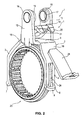
- a shift fork 1 according to the invention is shown, which comprises a base body 2.
- the main body 2 has two fork legs 3 and 4, which are arranged on a base plate 9 of the base body 2 via angled connecting plates 10 and 11 respectively.
- Each fork leg 3 and 4 has an associated recess 5 and 6, respectively.
- Fig. 1 illustrates here that the recesses 5 and 6, the respective wall thickness W 3 and W 4 of the fork legs 3 and 4 completely pass through, so that the recesses 5 and 6 thus represent breakthroughs through the cable legs 3 and 4.
- the recesses 3 and 4 extend over almost the entire length L 3 or L 4 of the fork legs 3 and 4 and extend respectively into an outwardly angled end portion 7 and 8.
- the recesses 5 and 6 are in this case in the middle in the respective fork leg third and 4 are arranged and have the shape of a slot, which has rectangular cross-section in the example shown.
- Fig. 1 also illustrates, are at the edge regions 26 and 27 of the base plate 9, so spaced from each other, guide sleeve webs 12 and 13, respectively, which are provided with a guide sleeve 14 and 15 respectively.
- the guide sleeves 14 and 15 are provided as usual with plain bearings 16 and 17 respectively.
- the guide webs 12 and 13 are upright, preferably arranged at a right angle to the base plate 9 at this.
- the guide sleeve web 12 also has a third guide in the form of a guide web 18.
- This guide web 18 may be formed as a breakthrough of the base plate 9, which in the in Fig. 1 apparent orientation is bent.
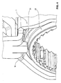
- the guide bar 18 protrudes from the base plate 9 in the direction of the switching jaw 25 and applies to the switching sleeve web 24, as is apparent from Fig. 2 results.
- a switching arm 19 is further arranged, which rises at an angle to the base plate 9 of this inclined.
- the switching arm 19 has in the example shown two switching arm legs 20 and 21, which limit a Wegarmausbloodung 22, as this in detail from the Fig. 1 and 2 results.
Landscapes
- Engineering & Computer Science (AREA)
- General Engineering & Computer Science (AREA)
- Mechanical Engineering (AREA)
- Gear-Shifting Mechanisms (AREA)
Abstract
Description
- Die Erfindung betrifft eine Schaltgabel für eine Schaltmuffe gemäß dem Oberbegriff des Anspruches 1.
- Eine derartige Schaltgabel ist aus der
DE 193 60 262 A1 bekannt. Der Grundköper der bekannten Schaltgabel besteht aus einem U-Profil, das eine Führungsnut aufweist, um einen Schaltmuffensteg einer Schaltmuffe umkreisen zu können. Das U-Profil des Grundkörpers ist hierbei voll tragend oder nur teilweise tragend ausgeführt. - Es ist demgegenüber Aufgabe der vorliegenden Erfindung eine Schaltgabe der im Oberbegriff des Anspruches 1 angegebenen Art zu schaffen, welches auf einfache Art und Weise ohne aufwendige Umformschritte und sich dabei ergebenden geringen Herstellungskosten reproduzierbar ist.
- Die Lösung dieser Aufgabe erfolgt durch die Merkmale des Anspruches 1.
- Vorteilhafterweise kann die erfindungsgemäße Schaltgabel als einfaches Blechteil ausgeführt werden. Der Schaltmuffensteg gleitet hierbei in je eine Aussparung der Gabelschenkel. Die Aussparungen können hierbei eine optimierte Kontur aufweisen, die bessere Beölung zwischen Schaltmuffe und Schaltgabe gewährleistet.
- Die Unteransprüche haben vorteilhafte Weiterbildungen der Erfindung zum Inhalt.
- Insbesondere durch das Vorsehen einer dritten Führung an der Schaltgabel, die beispieisweise durch einen einfachen Durchbruch und durch ein Umbiegen dieses Durchbruchs realisiert werden kann, kann ein zu starkes Verkippen der Schaltmuffe verhindert werden.
- Zu den weiteren Vorteilen der erfindungsgemäßen Schaltmuffe zählen geringe Herstellungskosten, das Entfallen des Erfordernisses einer Nachbearbeitung der Teile der Schaltmuffe und das Entfallen aufwendiger Umformschritte.
- Weitere Einzelheiten, Vorteile und Merkmale der vorliegenden Erfindung ergeben sich aus nachfolgender Beschreibung eines Ausführungsbeispiels anhand der Zeichnung. Es zeigt:
- Fig. 1
- eine perspektivische Darstellung einer erfindungsgemäßen Schaltgabel;
- Fig. 2
- eine perspektivische Darstellung der Schaltgabel gemäß
Fig. 1 im an einer Schaltmuffe angeordneten Zustand; - Fig. 3
- eine vergrößerte Darstellung eines Gabelschenkels eines Teils der Schaltmuffe gemäß
Fig. 2 ; und - Fig. 4
- eine weitere vergrößerte Darstellung eines oberen Bereichs der erfindungsgemäßen Schaltgabel und Schaltmuffe zur Erläuterung einer dritten Führungsmöglichkeit.
- Gemäß
Fig. 1 ist eine Ausführungsform einer erfindungsgemäßen Schaltgabel 1 dargestellt, die einen Grundkörper 2 umfasst. Der Grundkörper 2 weist zwei Gabelschenkel 3 und 4 auf, die an einer Grundplatte 9 des Grundkörpers 2 über abgewinkelte Verbindungsplatten 10 bzw. 11 angeordnet sind. Hieraus ergibt sich die Form eines Schaltmauls 25, die einen im Wesentlichen rechteckigen unteren Bereich und einen sich in Richtung auf die Grundplatte 9 daran anschließenden kegelstumpfförmigen Bereich umfasst. - Jeder Gabelschenkel 3 und 4 weist eine zugeordnete Aussparung 5 bzw. 6 auf.
Fig. 1 verdeutlicht hierbei, dass die Aussparungen 5 und 6 die jeweilige Wandstärke W3 bzw. W4 der Gabelschenkel 3 bzw. 4 komplett durchgreifen, so dass die Aussparungen 5 und 6 mithin Durchbrüche durch die Kabelschenkel 3 und 4 darstellen. Ferner erstrecken sich die Aussparungen 3 und 4 über nahezu die gesamte Länge L3 bzw. L4 der Gabelschenkel 3 und 4 und reichen jeweils in einen nach außen abgewinkelten Endbereich 7 bzw. 8. Die Aussparungen 5 und 6 sind hierbei mittig im jeweiligen Gabelschenkel 3 und 4 angeordnet und haben die Form eines Langlochs, das im dargestellten Beispielsfalle rechteckigen Querschnitt hat. - Hierdurch ergibt sich eine besonders vorteilhafte Führung für eine in
Fig. 2 dargestellten Schaltmuffensteg 24 einer Schaltmuffe 23 und eine bessere Beölung dieser Teile. - Wie
Fig. 1 ferner verdeutlicht, sind an den Randbereichen 26 und 27 der Grundplatte 9, also beabstandet zueinander, Führungshülsenstege 12 bzw. 13 angeordnet, die mit einer Führungshülse 14 bzw. 15 versehen sind. Die Führungshülsen 14 und 15 sind wie üblich mit Gleitlagern 16 bzw. 17 versehen. - Wie
Fig. 1 verdeutlicht, sind die Führungsstege 12 und 13 aufrecht, vorzugsweise im rechten Winkel zur Grundplatte 9 an dieser angeordnet. - Der Führungshülsensteg 12 weist ferner eine dritte Führung in Form eines Führungssteges 18 auf. Dieser Führungssteg 18 kann als ein Durchbruch aus der Grundplatte 9 ausgebildet sein, der in die in
Fig. 1 ersichtliche Ausrichtung umgebogen wird. Der Führungssteg 18 ragt hierbei von der Grundplatte 9 aus in Richtung auf das Schaltmaul 25 vor und legt sich an den Schaltmuffensteg 24 an, wie sich dies ausFig. 2 ergibt. - Auf der Grundplatte 9 ist ferner ein Schaltarm 19 angeordnet, der in einem wählbaren Winkel zur Grundplatte 9 von dieser geneigt aufragt.
- Der Schaltarm 19 weist im dargestellten Beispielsfalle zwei Schaltarmschenkel 20 und 21 auf, die eine Schaltarmausnehmung 22 begrenzen, wie sich dies im Einzelnen aus den
Fig. 1 und2 ergibt. - Der Eingriff des Schaltmuffensteges 24 in die Aussparung ergibt sich ferner aus der vergrößerten Darstellung der
Fig. 3 , in der beispielhaft der Gabelschenkel 4 mit seiner zugeordneten Aussparung 6 dargestellt ist. - Die Führung durch den Führungssteg 18 ergibt sich ferner aus der vergrößerten Darstellung der
Fig. 4 . - Neben der schriftlichen Offenbarung der Erfindung wird hiermit explizit auf deren zeichnerische Darstellung in den
Fig. 1 bis 4 , insbesondere betreffend die geometrische Ausbildung der Teile der Schaltgabel 1, verwiesen. -
- 1
- Schaltgabel, insbesondere als Blechteil ausgebildet
- 2
- Grundkörper
- 3, 4
- Gabelschenkel
- 5, 6
- Aussparung
- 7, 8
- abgewinkelter Endbereich
- 9
- Grundplatte
- 10, 11
- abgewinkelte Verbindungsplatten
- 12, 13
- Führungshülsenstege
- 14, 15
- Führungshülsen
- 16, 17
- Gleitlager
- 18
- dritte Führung / Führungssteg
- 19
- Schaltarm
- 20, 21
- Schaltarmschenkel
- 22
- Schaltarmausnehmung
- 23
- Schiebermuffe / Schaltmuffe
- 24
- Schaltmuffensteg
- 25
- Schaltmaul
- 26, 27
- Ränder
- 28
- Schaltgabelarretierung, die dafür sorgt, dass die Schaltgabel in Neutralstellung oder im geschalteten Zustand über eine Kontur in Position gehalten wird
Claims (7)
- Schaltgabel (1) für eine Schaltmuffe (23), die einen Schaltmuffensteg (24) aufweist,- mit einem Grundkörper (2), der ein Schaltmaul (25) zur Aufnahme der Schaltmuffe (23) aufweist, und- mit zwei Gabelschenkeln (3, 4), die das Schaltmaul (25) seitlich begrenzen und jeweils eine Aussparung (5, 6) zur Aufnahme des Schaltmuffenstegs (24) aufweisen,dadurch gekennzeichnet,- dass die Gabelschenkel (3, 4) gerade ausgebildet sind, und- dass die Aussparungen (5, 6) als Durchtrittsausnehmungen ausgebildet sind, die die gesamte Wandstärke (W3 bzw. W4) der Gabelschenkel (3 bzw. 4) durchgreifen.
- Schaltgabel nach Anspruch 1, dadurch gekennzeichnet, dass die Aussparungen (5, 6) jeweils als Langloch ausgebildet sind, die jeweils über nahezu die gesamte Länge (L3, L4) der Gabelschenkel (3 bzw. 4) verlaufen.
- Schaltgabel nach Anspruch 1 oder 2, dadurch gekennzeichnet, dass die Aussparungen (5, 6) mittig im jeweiligen Gabelschenkel (3 bzw. 4) angeordnet sind.
- Schaltgabel nach einem der Ansprüche 1 bis 3, dadurch gekennzeichnet, dass die Gabelschenkel (3, 4) nach außen abgewinkelte Endbereiche (7 bzw. 8) aufweisen.
- Schaltgabel nach einem der Ansprüche 1 bis 4, dadurch gekennzeichnet, dass der Grundkörper (2) eine Grundplatte (9) aufweist, an der die Gabelschenkel (3, 4) über abgewinkelte Verbindungsplatten (10 bzw. 12) angeordnet sind.
- Schaltgabel nach Anspruch 5, dadurch gekennzeichnet, dass an der Grundplatte (9) zumindest eine von einem Führungssteg (18) gebildete dritte Führung für den Schaltmuffensteg (24) angeordnet ist.
- Schaltgabel nach Anspruch 6, dadurch gekennzeichnet, dass der Führungssteg (18) aus einem abgebogenen Durchbruch aus der Grundplatte (9) ausgebildet ist.
Priority Applications (2)
| Application Number | Priority Date | Filing Date | Title |
|---|---|---|---|
| AT08020245T ATE541151T1 (de) | 2008-11-20 | 2008-11-20 | Schaltgabel für eine schaltmuffe |
| EP08020245A EP2189685B1 (de) | 2008-11-20 | 2008-11-20 | Schaltgabel für eine Schaltmuffe |
Applications Claiming Priority (1)
| Application Number | Priority Date | Filing Date | Title |
|---|---|---|---|
| EP08020245A EP2189685B1 (de) | 2008-11-20 | 2008-11-20 | Schaltgabel für eine Schaltmuffe |
Publications (2)
| Publication Number | Publication Date |
|---|---|
| EP2189685A1 true EP2189685A1 (de) | 2010-05-26 |
| EP2189685B1 EP2189685B1 (de) | 2012-01-11 |
Family
ID=40433800
Family Applications (1)
| Application Number | Title | Priority Date | Filing Date |
|---|---|---|---|
| EP08020245A Not-in-force EP2189685B1 (de) | 2008-11-20 | 2008-11-20 | Schaltgabel für eine Schaltmuffe |
Country Status (2)
| Country | Link |
|---|---|
| EP (1) | EP2189685B1 (de) |
| AT (1) | ATE541151T1 (de) |
Cited By (1)
| Publication number | Priority date | Publication date | Assignee | Title |
|---|---|---|---|---|
| JP2017003038A (ja) * | 2015-06-11 | 2017-01-05 | トヨタ自動車株式会社 | 車両用手動変速機 |
Citations (3)
| Publication number | Priority date | Publication date | Assignee | Title |
|---|---|---|---|---|
| JP2004324812A (ja) | 2003-04-25 | 2004-11-18 | Honda Motor Co Ltd | 変速機 |
| EP1548335A2 (de) | 2003-12-24 | 2005-06-29 | INA-Schaeffler KG | Schaltgabel |
| EP1566579A2 (de) * | 2004-02-19 | 2005-08-24 | Selzer Fertigungstechnik GmbH & Co.KG | Vorrichtung zur Übertragung von Schaltbewegungen in einem Kraftfahrzeug-Schaltgetriebe und Verfahren zu deren Herstellung |
-
2008
- 2008-11-20 EP EP08020245A patent/EP2189685B1/de not_active Not-in-force
- 2008-11-20 AT AT08020245T patent/ATE541151T1/de active
Patent Citations (3)
| Publication number | Priority date | Publication date | Assignee | Title |
|---|---|---|---|---|
| JP2004324812A (ja) | 2003-04-25 | 2004-11-18 | Honda Motor Co Ltd | 変速機 |
| EP1548335A2 (de) | 2003-12-24 | 2005-06-29 | INA-Schaeffler KG | Schaltgabel |
| EP1566579A2 (de) * | 2004-02-19 | 2005-08-24 | Selzer Fertigungstechnik GmbH & Co.KG | Vorrichtung zur Übertragung von Schaltbewegungen in einem Kraftfahrzeug-Schaltgetriebe und Verfahren zu deren Herstellung |
Cited By (1)
| Publication number | Priority date | Publication date | Assignee | Title |
|---|---|---|---|---|
| JP2017003038A (ja) * | 2015-06-11 | 2017-01-05 | トヨタ自動車株式会社 | 車両用手動変速機 |
Also Published As
| Publication number | Publication date |
|---|---|
| ATE541151T1 (de) | 2012-01-15 |
| EP2189685B1 (de) | 2012-01-11 |
Similar Documents
| Publication | Publication Date | Title |
|---|---|---|
| DE102016113409B4 (de) | Schiene für einen Sitz eines Kraftfahrzeuges sowie Sitzschienensystem für ein Kraftfahrzeug | |
| DE1680066B2 (de) | Schiebedachkonstruktion für Kraftfahrzeuge | |
| DE10125098A1 (de) | Schaltgabel für ein Wechselgetriebe mit einem gabelförmig ausgebildeten Grundkörper aus Blech | |
| DE60017217T2 (de) | Stange zur Begrenzung der Relativbewegung zwischen zwei starren Elementen | |
| DE202010018274U1 (de) | Geteilter Deckel für einen Behälter und Behälter mit einem geteilten Deckel | |
| WO2010072287A1 (de) | Schaltgabel | |
| EP2356347A1 (de) | Wälzkörperkäfig für eine möbelauszugsführung | |
| EP2189685B1 (de) | Schaltgabel für eine Schaltmuffe | |
| DE102014102626B4 (de) | Kettenglied für eine Energieführungskette | |
| EP2191174B1 (de) | Gleitlageranordnung für ein bewegbares schaltelement in einer schaltvorrichtung sowie schaltvorrichtung mit der gleitlageranordnung | |
| DE1678183A1 (de) | Parallelfuehrung fuer hin- und hergehend bewegbares Scherteil eines Rasierapparates | |
| EP2334957B1 (de) | Schaltanordnung für ein schaltgetriebe | |
| DE19946388A1 (de) | Gitterkabelrinne | |
| DE19943750B4 (de) | Übertragungselement zwischen einem Türgriff und einem Türschloß eines Kraftfahrzeugs | |
| DE102012209058A1 (de) | Scheibenwischvorrichtung | |
| DE3830107A1 (de) | Drehervorrichtung fuer webmaschinen | |
| DE10314937B4 (de) | Profilleiste aus Kunststoff zum Halten einer Vielzahl von elektrischen Leitungen | |
| DE102014215527A1 (de) | Schaltwellenvorrichtung für ein Schaltgetriebe sowie Fahrzeug mit der Schaltwellenvorrichtung | |
| EP0995373A1 (de) | Reihenverbindung für Mehrzweckstühle | |
| DE102005033891A1 (de) | Schelle zur Befestigung mindestens einer Leitung | |
| DE2644708C2 (de) | Schubriegelschloß für Möbel o.dgl. | |
| CH676283A5 (de) | ||
| DE102015004013A1 (de) | Jalousie insbesondere für ein Ablagefach in einem Kraftwagen | |
| DE3130058C2 (de) | Befestigungsvorrichtung für Griffstangen von Türen, Öffnungsklappen, Plattenhebern u.dgl. | |
| DE2512310C3 (de) | Elektromagnetisches Relais mit Winkelanker |
Legal Events
| Date | Code | Title | Description |
|---|---|---|---|
| PUAI | Public reference made under article 153(3) epc to a published international application that has entered the european phase |
Free format text: ORIGINAL CODE: 0009012 |
|
| AK | Designated contracting states |
Kind code of ref document: A1 Designated state(s): AT BE BG CH CY CZ DE DK EE ES FI FR GB GR HR HU IE IS IT LI LT LU LV MC MT NL NO PL PT RO SE SI SK TR |
|
| AX | Request for extension of the european patent |
Extension state: AL BA MK RS |
|
| 17P | Request for examination filed |
Effective date: 20101118 |
|
| 17Q | First examination report despatched |
Effective date: 20101229 |
|
| AKX | Designation fees paid |
Designated state(s): AT BE BG CH CY CZ DE DK EE ES FI FR GB GR HR HU IE IS IT LI LT LU LV MC MT NL NO PL PT RO SE SI SK TR |
|
| GRAP | Despatch of communication of intention to grant a patent |
Free format text: ORIGINAL CODE: EPIDOSNIGR1 |
|
| GRAS | Grant fee paid |
Free format text: ORIGINAL CODE: EPIDOSNIGR3 |
|
| GRAA | (expected) grant |
Free format text: ORIGINAL CODE: 0009210 |
|
| AK | Designated contracting states |
Kind code of ref document: B1 Designated state(s): AT BE BG CH CY CZ DE DK EE ES FI FR GB GR HR HU IE IS IT LI LT LU LV MC MT NL NO PL PT RO SE SI SK TR |
|
| REG | Reference to a national code |
Ref country code: GB Ref legal event code: FG4D Free format text: NOT ENGLISH |
|
| REG | Reference to a national code |
Ref country code: CH Ref legal event code: EP |
|
| REG | Reference to a national code |
Ref country code: AT Ref legal event code: REF Ref document number: 541151 Country of ref document: AT Kind code of ref document: T Effective date: 20120115 |
|
| REG | Reference to a national code |
Ref country code: IE Ref legal event code: FG4D |
|
| REG | Reference to a national code |
Ref country code: DE Ref legal event code: R096 Ref document number: 502008006089 Country of ref document: DE Effective date: 20120315 |
|
| REG | Reference to a national code |
Ref country code: NL Ref legal event code: VDEP Effective date: 20120111 |
|
| PG25 | Lapsed in a contracting state [announced via postgrant information from national office to epo] |
Ref country code: SI Free format text: LAPSE BECAUSE OF FAILURE TO SUBMIT A TRANSLATION OF THE DESCRIPTION OR TO PAY THE FEE WITHIN THE PRESCRIBED TIME-LIMIT Effective date: 20120111 |
|
| LTIE | Lt: invalidation of european patent or patent extension |
Effective date: 20120111 |
|
| PG25 | Lapsed in a contracting state [announced via postgrant information from national office to epo] |
Ref country code: BG Free format text: LAPSE BECAUSE OF FAILURE TO SUBMIT A TRANSLATION OF THE DESCRIPTION OR TO PAY THE FEE WITHIN THE PRESCRIBED TIME-LIMIT Effective date: 20120411 Ref country code: NO Free format text: LAPSE BECAUSE OF FAILURE TO SUBMIT A TRANSLATION OF THE DESCRIPTION OR TO PAY THE FEE WITHIN THE PRESCRIBED TIME-LIMIT Effective date: 20120411 Ref country code: LT Free format text: LAPSE BECAUSE OF FAILURE TO SUBMIT A TRANSLATION OF THE DESCRIPTION OR TO PAY THE FEE WITHIN THE PRESCRIBED TIME-LIMIT Effective date: 20120111 Ref country code: NL Free format text: LAPSE BECAUSE OF FAILURE TO SUBMIT A TRANSLATION OF THE DESCRIPTION OR TO PAY THE FEE WITHIN THE PRESCRIBED TIME-LIMIT Effective date: 20120111 Ref country code: IS Free format text: LAPSE BECAUSE OF FAILURE TO SUBMIT A TRANSLATION OF THE DESCRIPTION OR TO PAY THE FEE WITHIN THE PRESCRIBED TIME-LIMIT Effective date: 20120511 Ref country code: HR Free format text: LAPSE BECAUSE OF FAILURE TO SUBMIT A TRANSLATION OF THE DESCRIPTION OR TO PAY THE FEE WITHIN THE PRESCRIBED TIME-LIMIT Effective date: 20120111 |
|
| REG | Reference to a national code |
Ref country code: IE Ref legal event code: FD4D |
|
| PG25 | Lapsed in a contracting state [announced via postgrant information from national office to epo] |
Ref country code: PL Free format text: LAPSE BECAUSE OF FAILURE TO SUBMIT A TRANSLATION OF THE DESCRIPTION OR TO PAY THE FEE WITHIN THE PRESCRIBED TIME-LIMIT Effective date: 20120111 Ref country code: PT Free format text: LAPSE BECAUSE OF FAILURE TO SUBMIT A TRANSLATION OF THE DESCRIPTION OR TO PAY THE FEE WITHIN THE PRESCRIBED TIME-LIMIT Effective date: 20120511 Ref country code: FI Free format text: LAPSE BECAUSE OF FAILURE TO SUBMIT A TRANSLATION OF THE DESCRIPTION OR TO PAY THE FEE WITHIN THE PRESCRIBED TIME-LIMIT Effective date: 20120111 Ref country code: LV Free format text: LAPSE BECAUSE OF FAILURE TO SUBMIT A TRANSLATION OF THE DESCRIPTION OR TO PAY THE FEE WITHIN THE PRESCRIBED TIME-LIMIT Effective date: 20120111 Ref country code: GR Free format text: LAPSE BECAUSE OF FAILURE TO SUBMIT A TRANSLATION OF THE DESCRIPTION OR TO PAY THE FEE WITHIN THE PRESCRIBED TIME-LIMIT Effective date: 20120412 |
|
| PG25 | Lapsed in a contracting state [announced via postgrant information from national office to epo] |
Ref country code: CY Free format text: LAPSE BECAUSE OF FAILURE TO SUBMIT A TRANSLATION OF THE DESCRIPTION OR TO PAY THE FEE WITHIN THE PRESCRIBED TIME-LIMIT Effective date: 20120111 |
|
| PG25 | Lapsed in a contracting state [announced via postgrant information from national office to epo] |
Ref country code: DK Free format text: LAPSE BECAUSE OF FAILURE TO SUBMIT A TRANSLATION OF THE DESCRIPTION OR TO PAY THE FEE WITHIN THE PRESCRIBED TIME-LIMIT Effective date: 20120111 Ref country code: SE Free format text: LAPSE BECAUSE OF FAILURE TO SUBMIT A TRANSLATION OF THE DESCRIPTION OR TO PAY THE FEE WITHIN THE PRESCRIBED TIME-LIMIT Effective date: 20120111 Ref country code: CZ Free format text: LAPSE BECAUSE OF FAILURE TO SUBMIT A TRANSLATION OF THE DESCRIPTION OR TO PAY THE FEE WITHIN THE PRESCRIBED TIME-LIMIT Effective date: 20120111 Ref country code: RO Free format text: LAPSE BECAUSE OF FAILURE TO SUBMIT A TRANSLATION OF THE DESCRIPTION OR TO PAY THE FEE WITHIN THE PRESCRIBED TIME-LIMIT Effective date: 20120111 Ref country code: EE Free format text: LAPSE BECAUSE OF FAILURE TO SUBMIT A TRANSLATION OF THE DESCRIPTION OR TO PAY THE FEE WITHIN THE PRESCRIBED TIME-LIMIT Effective date: 20120111 Ref country code: IE Free format text: LAPSE BECAUSE OF FAILURE TO SUBMIT A TRANSLATION OF THE DESCRIPTION OR TO PAY THE FEE WITHIN THE PRESCRIBED TIME-LIMIT Effective date: 20120111 |
|
| PLBE | No opposition filed within time limit |
Free format text: ORIGINAL CODE: 0009261 |
|
| STAA | Information on the status of an ep patent application or granted ep patent |
Free format text: STATUS: NO OPPOSITION FILED WITHIN TIME LIMIT |
|
| PG25 | Lapsed in a contracting state [announced via postgrant information from national office to epo] |
Ref country code: SK Free format text: LAPSE BECAUSE OF FAILURE TO SUBMIT A TRANSLATION OF THE DESCRIPTION OR TO PAY THE FEE WITHIN THE PRESCRIBED TIME-LIMIT Effective date: 20120111 Ref country code: IT Free format text: LAPSE BECAUSE OF FAILURE TO SUBMIT A TRANSLATION OF THE DESCRIPTION OR TO PAY THE FEE WITHIN THE PRESCRIBED TIME-LIMIT Effective date: 20120111 |
|
| 26N | No opposition filed |
Effective date: 20121012 |
|
| REG | Reference to a national code |
Ref country code: DE Ref legal event code: R097 Ref document number: 502008006089 Country of ref document: DE Effective date: 20121012 |
|
| PG25 | Lapsed in a contracting state [announced via postgrant information from national office to epo] |
Ref country code: ES Free format text: LAPSE BECAUSE OF FAILURE TO SUBMIT A TRANSLATION OF THE DESCRIPTION OR TO PAY THE FEE WITHIN THE PRESCRIBED TIME-LIMIT Effective date: 20120422 |
|
| BERE | Be: lapsed |
Owner name: HOERBIGER SYNCHRONTECHNIK G.M.B.H. & CO. KG Effective date: 20121130 |
|
| REG | Reference to a national code |
Ref country code: CH Ref legal event code: PL |
|
| GBPC | Gb: european patent ceased through non-payment of renewal fee |
Effective date: 20121120 |
|
| PG25 | Lapsed in a contracting state [announced via postgrant information from national office to epo] |
Ref country code: LI Free format text: LAPSE BECAUSE OF NON-PAYMENT OF DUE FEES Effective date: 20121130 Ref country code: CH Free format text: LAPSE BECAUSE OF NON-PAYMENT OF DUE FEES Effective date: 20121130 |
|
| REG | Reference to a national code |
Ref country code: FR Ref legal event code: ST Effective date: 20130731 |
|
| PG25 | Lapsed in a contracting state [announced via postgrant information from national office to epo] |
Ref country code: BE Free format text: LAPSE BECAUSE OF NON-PAYMENT OF DUE FEES Effective date: 20121130 |
|
| PG25 | Lapsed in a contracting state [announced via postgrant information from national office to epo] |
Ref country code: GB Free format text: LAPSE BECAUSE OF NON-PAYMENT OF DUE FEES Effective date: 20121120 Ref country code: MT Free format text: LAPSE BECAUSE OF FAILURE TO SUBMIT A TRANSLATION OF THE DESCRIPTION OR TO PAY THE FEE WITHIN THE PRESCRIBED TIME-LIMIT Effective date: 20120111 Ref country code: FR Free format text: LAPSE BECAUSE OF NON-PAYMENT OF DUE FEES Effective date: 20121130 |
|
| PG25 | Lapsed in a contracting state [announced via postgrant information from national office to epo] |
Ref country code: MC Free format text: LAPSE BECAUSE OF NON-PAYMENT OF DUE FEES Effective date: 20121130 Ref country code: TR Free format text: LAPSE BECAUSE OF FAILURE TO SUBMIT A TRANSLATION OF THE DESCRIPTION OR TO PAY THE FEE WITHIN THE PRESCRIBED TIME-LIMIT Effective date: 20120111 |
|
| PG25 | Lapsed in a contracting state [announced via postgrant information from national office to epo] |
Ref country code: LU Free format text: LAPSE BECAUSE OF NON-PAYMENT OF DUE FEES Effective date: 20121120 |
|
| PG25 | Lapsed in a contracting state [announced via postgrant information from national office to epo] |
Ref country code: HU Free format text: LAPSE BECAUSE OF FAILURE TO SUBMIT A TRANSLATION OF THE DESCRIPTION OR TO PAY THE FEE WITHIN THE PRESCRIBED TIME-LIMIT Effective date: 20081120 |
|
| REG | Reference to a national code |
Ref country code: AT Ref legal event code: MM01 Ref document number: 541151 Country of ref document: AT Kind code of ref document: T Effective date: 20131120 |
|
| PG25 | Lapsed in a contracting state [announced via postgrant information from national office to epo] |
Ref country code: AT Free format text: LAPSE BECAUSE OF NON-PAYMENT OF DUE FEES Effective date: 20131120 |
|
| PGFP | Annual fee paid to national office [announced via postgrant information from national office to epo] |
Ref country code: DE Payment date: 20170131 Year of fee payment: 9 |
|
| REG | Reference to a national code |
Ref country code: DE Ref legal event code: R119 Ref document number: 502008006089 Country of ref document: DE |
|
| PG25 | Lapsed in a contracting state [announced via postgrant information from national office to epo] |
Ref country code: DE Free format text: LAPSE BECAUSE OF NON-PAYMENT OF DUE FEES Effective date: 20180602 |