EP2189088B1 - Beverage distribution apparatus with support system and droplet recuperation for containers with different sizes - Google Patents
Beverage distribution apparatus with support system and droplet recuperation for containers with different sizes Download PDFInfo
- Publication number
- EP2189088B1 EP2189088B1 EP10154892.3A EP10154892A EP2189088B1 EP 2189088 B1 EP2189088 B1 EP 2189088B1 EP 10154892 A EP10154892 A EP 10154892A EP 2189088 B1 EP2189088 B1 EP 2189088B1
- Authority
- EP
- European Patent Office
- Prior art keywords
- support
- container
- support element
- pushed back
- unfolded
- Prior art date
- Legal status (The legal status is an assumption and is not a legal conclusion. Google has not performed a legal analysis and makes no representation as to the accuracy of the status listed.)
- Active
Links
Images

Classifications
-
- A—HUMAN NECESSITIES
- A47—FURNITURE; DOMESTIC ARTICLES OR APPLIANCES; COFFEE MILLS; SPICE MILLS; SUCTION CLEANERS IN GENERAL
- A47J—KITCHEN EQUIPMENT; COFFEE MILLS; SPICE MILLS; APPARATUS FOR MAKING BEVERAGES
- A47J31/00—Apparatus for making beverages
- A47J31/44—Parts or details or accessories of beverage-making apparatus
- A47J31/4482—Details allowing to adapt the beverage-making apparatus to the size of the brewing vessel or the beverage container, e.g. with adjustable support for the beverage container or adjustable hot water outlet
Definitions
- the present invention relates to a beverage dispensing device, such as a coffee machine, having a drop recovery system suitable for containers of different sizes.
- beverage dispensing machines such as coffee machines
- coffee machines that can deliver different beverages in containers of different sizes, including machines of the type disclosed in the patent.
- US5,161,455 there are coffee machines to prepare espresso or long coffee in a small or medium cup and a coffee "macchiato" in a tall glass.
- Some devices are formed of a plurality of superimposed support members. The user must manipulate one or more of these elements to be able to correctly adapt the support to the size of the desired container with the risk of spilling the collected liquid. There is also the risk for the user to not respect the correct outlet-container distance depending on the dispensed beverage. For example, it may be necessary to use a support too low for a coffee served in a cup.
- the present invention aims to provide a solution that meets the above requirements and solves the disadvantages of the prior art.
- the invention relates to a device for the preparation of drinks, such as a coffee machine.
- the device comprises a base, a drink outlet and a system for supporting and recovering drops.
- the system includes a support member positionable beneath the beverage outlet for receiving a relatively small container.
- the support element is movable in an extended support position adapted to receive a small container and a position at least partially pushed in which the element is pushed to release a free space downwards to position a second larger container in place of the first container, under the drink outlet.
- the cup support member is preferably overhanging relative to the base in the extended position of a beverage in the small container and is arranged to be repulsed to release a space for positioning a container. larger size under the drink outlet.
- the support member is overhanging at a predetermined vertical distance from the lower plane of the base.
- the distance is such that a small container can not push back the support member sufficiently while a large container is able to repel said element.
- the support and collection means used for the small container (for example, a cup) is simply pushed back when a large container is used. It can thus be repelled by the container itself, for example, a large glass.
- This principle also ensures an optimum distance to deliver the drink including avoiding any risk of confusion in the control of the positioning of the container under the drink outlet.
- the support member is movable in rotation. It is preferably pushed back in rotation when placing a container of sufficient height that can bear against the element and thus maintain the pushed position.
- the support element is articulated integrally with the device by a substantially horizontal axis of rotation for pushing said element upwards.
- the support member is arranged in articulation on the device so that it can be pushed at least partially during the positioning of a larger container and to fall by gravity under the drink outlet at the moment when the user removes said container.
- the last drops from the drink outlet can be retrieved by the support member itself when the user removes the large container from the service area.
- the system comprises a liquid collector which is arranged to receive the liquid recovered by the support member at the moment when it is positioned in the pushed-back position.
- the support member can be emptied regularly; This reduces the risk of overflow of liquid, improves the cleanliness of the device and reduces hygiene problems.
- the support element and the collecting tray are integral to form a drawer which is removable relative to the base.
- the support element can be articulated removably on the collector itself or any other integral part of the drawer.
- the device of the invention may also comprise a locking device of the support element in fully pushed position.
- the locking device can be arranged to automatically release the support member in the deployed position. Once released by the locking device, the support member may fall, for example, by gravity in the deployed position.
- a lock may be useful in particular for performing maintenance and / or when the device has not been used to reduce its size.
- the replacement of the support element may be automatic, that is to say not requiring manipulation of the support itself. In this way, the risk is reduced to then be able to place a small container while the element is still locked in raised or pushed position.
- the locking means are controlled by the device power on / off means. More specifically, when the device is powered by the start button, the pressure exerted on the button causes an unlocking of the locking means.
- the control of the button on the locking means may be mechanical, electromagnetic and / or electrical, for example.
- the coffee machine comprises a base 2 which can cover a set of assembled parts such as an internal framework 3 (illustrated in FIGS. figures 2-3 ) on which are adapted different external panels 4, 5, 6.
- the machine comprises a drink outlet 7 which can take different forms.
- the machine also includes, for example, means 8 for closing the extraction or percolation module.
- the machine may include internally an extraction module for extracting, dissolving and / or diluting the food ingredient under pressure and delivering it through the outlet of drink.
- the food ingredient is preferably contained in a closed package such as a capsule, a sachet or any other suitable packaging for the machine.
- the device according to the invention comprises a container support system and collection or recovery of drops 9.
- the system is formed of a support member 10 which is positioned under the drink outlet and overhanging the machine.
- overhang is meant that the support member extends the device in at least one direction and is not supported from below so as to form a kind of balcony.
- the support member is placed at a distance D with respect to the predefined drink outlet so as to optimize the flow distance when receiving small or medium-sized containers (i.e. mugs that can hold approximately 25, 40 or 110 mL respectively).
- the element is spaced a distance "d" from the placement surface 11 for positioning a larger container when the element is pushed back by the container.
- the placement surface or support of the container can be virtual, that is to say, simply that of a kitchen table or other surface that is not part of the machine itself or "real, that is to say that is, to be part of a support surface of the machine itself, but the invention is of interest in the simplification of the machine and therefore it is not necessary to provide a specific support for the large container. (hereinafter referred to as "tall glass”) as will be explained later.
- the support member 10 is thus freely movable in rotation along an axis of rotation I relative to the base.
- the element can be pushed up or "up", in this case, it allows the positioning of a large glass.
- the large glass simply pushes the support element up.
- the bearing may be partial so that the element is not fully housed in the housing 12 provided in the base.
- the outlet 7 is also provided so that the distance D1 between the outlet and the placement surface 11 is optimal for a large glass, so as to limit the risk of splashing and allow a close flow that does not harm the the foam in formation or already formed in the glass.
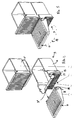
- the Figures 2 and 3 show the support and collection system 9 as such.
- the system is in the form of a drawer assembly.
- a first collecting pan 13 is provided for recovering the liquid from the support member 10.
- the element support is articulated removably on the side faces of the collector tank 13 by lugs 14 relating in the slots 15 faces.
- the support member comprises on the sides of the bearing surfaces 16 placed below the axis of rotation, so as to engage in abutment against front surfaces 17 of the tray. In this way, the support element is held overhanging while freeing a space 18 under the element.
- the support element provides a strong support for the removal of a cup of small / medium capacity.
- the drip tray may be provided with a chute 20 which projects under the support member and thus ensures better recovery of the liquid.
- a second recovery tank 21 for the coffee capsules can fit onto the first collection tray 13. Once installed in the machine, the tray 21 is arranged to recover the used capsules ejected by the extraction module.
- the support and collection system 9 forms a single modular block which can be easily disengaged from the base by simple sliding, for example, thus making maintenance easier, namely, the emptying of both the liquid and used capsules and cleaning bins.
- the support and collection system 9 engages sliding in a housing 22 of the base of the machine. Once in place, the system is then functionally and aesthetically integrated with the rest of the machine.
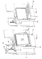
- the machine also preferably comprises a locking device 23 making it possible to lock the support element 10 in a fully retracted or pushed-back position, such as, for example, in part at least in the housing 22.
- a locking device 23 comprises locking means which are associated with a control means. The control means acts on the locking means to selectively release the support member. The support element is then released in rotation to its deployed position ( figure 5 ).
- the control means preferably includes the on / off button 26 of the machine for turning on the machine.
- This means is as known in itself associated with an electric switch 27 for selectively feeding the electrical and electronic components of the machine (water heater, pump, electronic control, etc.).
- the on / off button 26 is mechanically connected to a latch 28 formed, for example, by a mechanical pusher 29 which activates a latch 30 secured to a retaining finger 31 acting as a retainer on the front edge of the latch.
- the rocker member 30 may be associated with resilient means (eg, a spring) to provide for the automatic return of the finger to the lock position after suppressing the pressure on the start / stop button as shows it figure 5 .
- the advantage of associating the locking of the support member in the retracted position with the on / off control is to avoid the situation allowing the user to prepare a beverage in a small container when the support element is Locked.
- the user wants to make coffee in a cup, for example, as opposed to a tall glass, he must first press the on / off button; which activates the lock in opening and releases the support element.
- the on / off button which activates the lock in opening and releases the support element.
Abstract
Description
La présente invention se rapporte à un dispositif de distribution de boissons, telle qu'une machine à café, disposant d'un système de récupération de gouttes adapté pour récipients de différentes tailles.The present invention relates to a beverage dispensing device, such as a coffee machine, having a drop recovery system suitable for containers of different sizes.
Il existe une demande des consommateurs pour des machines de distribution de boissons, telle que des machines à café, qui puissent délivrer différentes boissons dans des récipients de différentes tailles, notamment des machines du type divulgué dans le brevet
Par ailleurs, il est important de maintenir une faible distance entre la sortie de boisson et le récipient de façon à garantir une bonne qualité de crème ("crema") pour un café et d'autre part éviter les risques de projections. Il faut donc un système qui empêche à l'utilisateur de faire d'erreur par rapport au support utilisé et dans la bonne distance entre la sortie de la boisson et le recipient.Moreover, it is important to maintain a short distance between the outlet of the beverage and the container so as to ensure a good quality of cream ("crema") for a coffee and also avoid the risk of projections. It is therefore necessary a system that prevents the user from making mistakes in relation to the support used and in the good distance between the outlet of the beverage and the container.
Par ailleurs, il est aussi important de proposer un système de récupération des gouttes qui soit efficace afin de garantir une certaine propreté dans la zone de service.In addition, it is also important to provide a drop recovery system that is effective to ensure cleanliness in the service area.
Il est aussi important de proposer un système qui soit facile d'utilisation et sans complexité technique.It is also important to provide a system that is easy to use and without technical complexity.
Il faut aussi que le système puisse être d'une maintenance aisée.It is also necessary that the system can be of easy maintenance.
Les dispositifs existants dans l'art antérieur ne répondent correctement pas à ces objets.The existing devices in the prior art do not respond correctly to these objects.
Certains dispositifs sont formés de plusieurs éléments de support placés en superposition. L'utilisateur doit manipuler un ou plusieurs des ces éléments pour pouvoir correctement adapter le support à la taille du récipient voulu avec le risque de renverser le liquide collecté. Il y aussi le risque pour l'utilisateur de ne pas respecter la bonne distance sortie-récipient en fonction de la boisson distribuée. Par exemple, il peut être amené à utiliser un support trop bas pour un café servi dans une tasse.Some devices are formed of a plurality of superimposed support members. The user must manipulate one or more of these elements to be able to correctly adapt the support to the size of the desired container with the risk of spilling the collected liquid. There is also the risk for the user to not respect the correct outlet-container distance depending on the dispensed beverage. For example, it may be necessary to use a support too low for a coffee served in a cup.
La présente invention vise à proposer une solution qui répond aux exigences précitées et résout les inconvénients de l'art antérieur.The present invention aims to provide a solution that meets the above requirements and solves the disadvantages of the prior art.
Pour cela, l'invention concerne un dispositif pour la préparation de boissons, telle qu'une machine à café. Le dispositif comprend une embase, une sortie de boisson et un système de support et de récupération de gouttes. Le système comprend un élément de support positionnable sous la sortie de boisson pour recevoir un récipient de relativement petite taille. Selon un aspect de l'invention, l'élement de support est mobile selon une position déployée de support adaptée pour recevoir un récipient de petite taille et une position au moins partiellement repoussée dans laquelle l'élément est repoussé de façon à libérer un espace libre vers le bas permettant de positionner un second récipient de plus grande taille, à la place du premier récipient, sous la sortie de boisson.For this, the invention relates to a device for the preparation of drinks, such as a coffee machine. The device comprises a base, a drink outlet and a system for supporting and recovering drops. The system includes a support member positionable beneath the beverage outlet for receiving a relatively small container. According to one aspect of the invention, the support element is movable in an extended support position adapted to receive a small container and a position at least partially pushed in which the element is pushed to release a free space downwards to position a second larger container in place of the first container, under the drink outlet.
L'élément de support de tasse est de préférence agencé en surplomb relativement à l'embase en position déployée d'une boisson dans le récipient de petite taille et est arrangé pour pouvoir être repoussé de façon à libérer un espace permettant de positionner un récipient de plus grande taille sous la sortie de boisson.The cup support member is preferably overhanging relative to the base in the extended position of a beverage in the small container and is arranged to be repulsed to release a space for positioning a container. larger size under the drink outlet.
De préférence, l'élément de support est placé en surplomb à une distance verticale prédéterminée par rapport au plan inférieur de l'embase. Par exemple, la distance est telle qu'un récipient de petite taille ne peut pas repousser l'élément de support suffisamment alors qu'un récipient de grande taille est capable de repousser ledit élément.Preferably, the support member is overhanging at a predetermined vertical distance from the lower plane of the base. For example, the distance is such that a small container can not push back the support member sufficiently while a large container is able to repel said element.
Ainsi, selon le concept inventif, le moyen de support et de collecte utilisé pour le récipient de petite taille (par exemple, une tasse) est repoussé simplement lorsqu'un récipient de grande taille est utilisé. Il peut ainsi être repoussé par le récipient lui-même, par exemple, un grand verre. On garantit aussi par ce principe une distance optimale pour délivrer la boisson notamment en évitant tout risque de confusion dans le contrôle du positionnement du récipient sous la sortie de boisson.Thus, according to the inventive concept, the support and collection means used for the small container (for example, a cup) is simply pushed back when a large container is used. It can thus be repelled by the container itself, for example, a large glass. This principle also ensures an optimum distance to deliver the drink including avoiding any risk of confusion in the control of the positioning of the container under the drink outlet.
Selon un mode possible, l'élément de support est déplaçable en rotation. Il est préférablement repoussé en rotation vers le haut lors du placement d'un récipient de hauteur suffisante qui peut prendre appui contre l'élément et le maintenir ainsi en position repoussée. Par exemple, l'élément de support est articulé solidairement au dispositif par un axe de rotation sensiblement horizontal permettant de repousser ledit élément vers le haut.In one possible mode, the support member is movable in rotation. It is preferably pushed back in rotation when placing a container of sufficient height that can bear against the element and thus maintain the pushed position. For example, the support element is articulated integrally with the device by a substantially horizontal axis of rotation for pushing said element upwards.
De préférence, l'élément de support est agencé en articulation sur le dispositif de façon à pouvoir être repoussé au moins partiellement lors du positionnement d'un récipient de plus grande taille et à retomber par gravité sous la sortie de boisson au moment ou l'utilisateur enlève ledit récipient. Ainsi, les dernières gouttes provenant de la sortie de boisson peuvent être récupérées par l'élément de support lui-même au moment ou l'utilisateur enlève le récipient de grande taille de la zone de service.Preferably, the support member is arranged in articulation on the device so that it can be pushed at least partially during the positioning of a larger container and to fall by gravity under the drink outlet at the moment when the user removes said container. Thus, the last drops from the drink outlet can be retrieved by the support member itself when the user removes the large container from the service area.
Selon un autre aspect possible, le système comprend un bac collecteur de liquide lequel est disposé pour recevoir le liquide récupéré par l'élément de support au moment où celui-ci est positionné en position repoussée. Ainsi, l'élément de support peut être vidé régulièrement; ce qui diminue les risques de débordement de liquide, améliore la propreté du dispositif et réduit les problèmes d'hygiène.According to another possible aspect, the system comprises a liquid collector which is arranged to receive the liquid recovered by the support member at the moment when it is positioned in the pushed-back position. Thus, the support member can be emptied regularly; This reduces the risk of overflow of liquid, improves the cleanliness of the device and reduces hygiene problems.
Selon une construction préférentielle, l'élément de support et le bac collecteur sont solidaires pour former un tiroir lequel est amovible par rapport à l'embase. Dans ce cas, l'élément de support peut être articulé de manière amovible sur le bac collecteur lui-même ou toute autre pièce solidaire du tiroir. Ce concept modulaire de tiroir rend la maintenance plus aisée et permet un nettoyage de l'ensemble du système de support et de collecte.According to a preferred construction, the support element and the collecting tray are integral to form a drawer which is removable relative to the base. In this case, the support element can be articulated removably on the collector itself or any other integral part of the drawer. This modular drawer concept makes maintenance easier and allows cleaning of the entire support and collection system.
Le dispositif de l'invention peut aussi comprendre un dispositif de verrouillage de l'élément de support en position entièrement repoussée. Le dispositif de verrouillage peut être arrangé de façon à libérer automatiquement l'élément de support en position déployée. Une fois libéré par le dispositif de verrouillage, l'élément de support peut retomber, par exemple, par gravité en position déployée. Un verrouillage peut être utile notamment pour effectuer la maintenance et/ou lorsque le dispositif n'est pas été utilisé de façon à réduire son encombrement. La remise en place de l'élément de support peut être automatique, c'est à dire ne nécessitant pas de manipulations du support lui-même. De la sorte, le risque est réduit de pouvoir alors placer un récipient de petite taille alors que l'élément est encore verrouillé en position relevée ou repoussée.The device of the invention may also comprise a locking device of the support element in fully pushed position. The locking device can be arranged to automatically release the support member in the deployed position. Once released by the locking device, the support member may fall, for example, by gravity in the deployed position. A lock may be useful in particular for performing maintenance and / or when the device has not been used to reduce its size. The replacement of the support element may be automatic, that is to say not requiring manipulation of the support itself. In this way, the risk is reduced to then be able to place a small container while the element is still locked in raised or pushed position.
Selon un mode préférentiel, les moyens de verrouillage sont contrôlés par le moyen de mise sous tension "marche/arrêt" du dispositif. Plus précisément, lorsque le dispositif est mis sous tension par le bouton de mise en marche, la pression exercée sur le bouton entraîne un déverrouillage des moyens de verrouillage. Le contrôle du bouton sur les moyens de verrouillage peut être de nature mécanique, électromagnétique et/ou électrique par exemple.According to a preferred embodiment, the locking means are controlled by the device power on / off means. More specifically, when the device is powered by the start button, the pressure exerted on the button causes an unlocking of the locking means. The control of the button on the locking means may be mechanical, electromagnetic and / or electrical, for example.
L'invention n'est pas nécessairement limitée à un élément de support agencé en rotation. On peut prévoir aussi un mode de réalisation dans lequel l'élément est repoussé par d'autres moyens tel que par glissement à la manière d'un tiroir dans un logement du dispositif.
- La
figure 1 représente en vue en perspective un dispositif selon l'invention; - La
figure 2 montre un détail du système de support et de récupération selon l'invention en vue éclatée; - La
figure 3 montre un détail du système de support et de récupération selon l'invention en assemblage sous forme de tiroir; - La
figure 4 représente une vue de détail en perspective d'une partie du dispositif dans lequel le système de support et de récupération de gouttes est en position verrouillée; - La
figure 5 représente une vue de détail d'une partie du dispositif avec le système déployée pour recevoir des récipients de petite ou moyenne tailles.
- The
figure 1 represents in perspective view a device according to the invention; - The
figure 2 shows a detail of the support and recovery system according to the invention in exploded view; - The
figure 3 shows a detail of the support and recovery system according to the invention as a drawer assembly; - The
figure 4 is a detailed perspective view of a portion of the device in which the support and drop recovery system is in the locked position; - The
figure 5 is a detail view of a part of the device with the system deployed to receive containers of small or medium sizes.
Par référence aux figures, le dispositif pour la préparation de boisson porte la référence 1 et sera appelé par simplification "machine à café" dans la suite de la description. La machine à café selon l'invention comprend une embase 2 pouvant recouvrir un ensemble de pièces assemblées comme une ossature interne 3 (illustrée aux
La technique d'extraction ou de dilution n'étant pas l'objet de l'invention, il n'est pas nécessaire de décrire celle-ci. Pour exemple seulement, la machine peut comprendre en interne un module d'extraction servant à extraire, dissoudre et/ou diluer l'ingrédient alimentaire sous pression et le délivrer au travers de la sortie de boisson. L'ingrédient alimentaire est de préférence contenu dans un emballage fermé tel qu'une capsule, un sachet ou tout autre emballage adapté pour la machine.The extraction or dilution technique is not the subject of the invention, it is not necessary to describe it. For example only, the machine may include internally an extraction module for extracting, dissolving and / or diluting the food ingredient under pressure and delivering it through the outlet of drink. The food ingredient is preferably contained in a closed package such as a capsule, a sachet or any other suitable packaging for the machine.
Le dispositif selon l'invention comprend un système de support de récipient et de collecte ou récupération des gouttes 9. Le système est formé d'un élément de support 10 qui se positionne sous la sortie de boisson et en surplomb de la machine. Par positionnement en "surplomb", il faut entendre que l'élément de support prolonge le dispositif dans au moins une direction et n'est pas supportée par dessous de façon à former ainsi une sorte de balcon. L'élément de support est placé à une distance D par rapport à la sortie de boisson prédéfinie de façon à optimiser la distance d'écoulement lors de la réception de récipients de petites ou moyennes tailles (c'est à dire, par exemple, des tasses pouvant contenir respectivement environ 25, 40 ou 110 mL). Aussi, l'élément est distant d'une distance "d" de la surface de placement 11 pour le positionnement d'un récipient de plus grande taille lorsque l'élément est repoussé par le récipient. La surface de placement ou support du récipient peut être virtuelle, c'est à dire, simplement celle d'une table de cuisine ou autre surface ne faisant pas partie de la machine elle-même ou encore "réelle, c'est-à-dire, faire partie d'une surface de support de la machine elle-même. Toutefois, l'invention trouve un intérêt dans la simplification de la machine et donc il n'est pas nécessaire de prévoir un support spécifique pour le récipient de grande taille (ci-après dénommé "grand verre") comme il sera expliqué plus loin.The device according to the invention comprises a container support system and collection or recovery of
L'élément de support 10 est ainsi déplaçable librement en rotation selon un axe de rotation I relativement à l'embase. L'élément peut se trouver en position repoussée vers le haut ou "relevé", dans ce cas, il permet le positionnement d'un grand verre. Le grand verre repousse simplement l'élément de support qui se relève. Le relèvement peut être partiel de sorte que l'élément ne soit pas entièrement logé dans le logement 12 prévu dans l'embase. La sortie de boisson 7 est aussi prévue de sorte que la distance D1 entre la sortie et la surface de placement 11 soit optimale pour un grand verre, de façon à limiter notamment les risques d'éclaboussures et permettre un écoulement rapproché qui ne nuit pas à la mousse en formation ou déjà formée dans le verre.The
Les
Un second bac de récupération 21 pour les capsules de café peut s'emboîter sur le premier bac collecteur 13. Une fois installé dans la machine, le bac 21 est agencé pour récupérer les capsules usagées éjectées par le module d'extraction.A second recovery tank 21 for the coffee capsules can fit onto the
Le système de support et de collecte 9 selon l'invention forme un seul bloc modulaire qui peut être facilement désengagé de l'embase par simple glissement, par exemple, rendant ainsi plus aisé la maintenance, à savoir, la vidange à la fois du liquide et des capsules usagées et le nettoyage des bacs.The support and
Comme le montrent les
La machine comprend aussi préférentiellement un dispositif de verrouillage 23 permettant de verrouiller l'élément de support 10 dans une position entièrement rétractée ou repoussée, comme par exemple, en partie au moins dans le logement 22. Tout moyen de verrouillage est envisageable comme des moyens mécaniques ou à électro-aimants. Selon un mode préférentiel, le dispositif de verrouillage comprend des moyens de verrouillage qui sont associés à un moyen de contrôle. Le moyen de contrôle agit sur les moyens de verrouillage pour libérer sélectivement l'élément de support. L'élément de support est alors libéré en rotation jusqu'à sa position déployée (
Le moyen de contrôle inclut préférentiellement le bouton marche/arrêt 26 de la machine permettant de mettre la machine sous tension. Ce moyen est comme connu en soi associé à un interrupteur électrique 27 permettant d'alimenter sélectivement les composants électriques et électroniques de la machine (chauffe-eau, pompe, contrôle électronique, etc.). Dans ce cas particulier, le bouton marche/arrêt 26 est relié mécaniquement à un verrou 28 formé, par exemple, par un poussoir mécanique 29 qui active une bascule 30 solidaire d'un doigt de retenue 31 agissant en retenue sur le bord avant de l'élément de support 10. L'élément de bascule 30 peut être associé à des moyens élastiques (par exemple, un ressort) afin de prévoir le retour automatique du doigt en position de verrouillage après suppression de la pression sur le bouton marche/arrêt comme le montre la
L'avantage d'associer le verrouillage de l'élément de support en position rétractée au contrôle marche/arrêt est d'éviter la situation permettant à l'utilisateur de préparer une boisson dans un récipient de petite taille lorsque l'élément de support est verrouillé. Lorsque l'utilisateur veut préparer un café dans une tasse, par exemple, par opposition à un grand verre, il doit d'abord appuyer sur le bouton marche/arrêt; ce qui active le verrou en ouverture et libère l'élément de support. A contrario, s'il veut préparer une boisson dans une grande tasse, il lui suffit de repousser partiellement l'élément de support 10 en rotation vers le haut au moyen du grand verre.The advantage of associating the locking of the support member in the retracted position with the on / off control is to avoid the situation allowing the user to prepare a beverage in a small container when the support element is Locked. When the user wants to make coffee in a cup, for example, as opposed to a tall glass, he must first press the on / off button; which activates the lock in opening and releases the support element. Conversely, if he wants to prepare a drink in a large cup, it is sufficient to partially push the
Claims (15)
- A device (1) for the preparation of beverages configured such that it can be placed on a surface or support surface (11) such as a kitchen table surface, said device (1) comprising a housing (2) and a support system and droplet recuperation system, which comprises a support element (10) positionable under a beverage outlet (7) to receive a first container of relatively small size, the support element being movable between an unfolded support position adapted to receive a container of small size and an at least partly pushed back position in which the element is pushed back such that it releases a free space permitting to position a second, larger container instead of the first container under the beverage outlet, characterised in that said device is configured to release a virtual free space (11) for said second container, said virtual free space being delimited by said surface or support surface.
- The device according to claim 1, characterised in that the position pushed back towards the top of the support element (10) is outside of the housing (2).
- The device according to claim 1 or 2, characterised in that the element (10) is movable in a rotary motion between the unfolded position and the pushed back position.
- The device according to claim 3, characterised in that the support element (10) is articulated according to a rotational axis permitting to push back said element towards the top.
- The device according to any one of the preceding claims, characterised in that the support element (10) is placed overhanging with respect to the housing (2) in unfolded support position of the first container.
- The device according to claim 5, characterised in that the support element (10) comprises a bearing surface (16) intended to provide a support to maintain the element in unfolded position overhanging.
- The device according to any one of the preceding claims, characterised in that the support element (10) is located in an articulated manner such that it can be pushed back at least partially when a higher container is placed and fall back by gravity under the beverage outlet (7) when the user removes said container.
- The device according to any one of the preceding claims, characterised in that the movable support element (10) is arranged for the recuperation of liquid in unfolded position.
- The device according to claim 8, characterised in that the system comprises a liquid collecting vessel (13), which is located to receive the liquid collected by the support element (10) when it is placed in unfolded position.
- The device according to claim 9, characterised in that the support element (10) and the collecting vessel (13) are integral to form a drawer which is detachable with respect to the housing (2).
- The device according to any one of the preceding claims, characterised in that it comprises a locking device (23) of the element (10) in completely pushed back position, with the locking device being arranged such that the element in unfolded position is automatically released by an On/Off means (26).
- The device according to claim 11, characterised in that the support element (10) is locked in pushed back position so that it falls back by gravity in unfolded position as soon as it is released by the locking device (23).
- The device according to claims 11 or 12, characterised in that the locking device (23) is controlled by an On/Off means (26).
- The device according to any one of the preceding claims, characterised in that the element (10) is shifted alongside or in an accommodation (12, 12) of the housing (2).
- The device according to claim 14, characterised in that it comprises an accommodation (12, 22) into which the support element (10) is slidingly inserted.
Priority Applications (2)
| Application Number | Priority Date | Filing Date | Title |
|---|---|---|---|
| EP10154892.3A EP2189088B1 (en) | 2006-06-16 | 2006-06-16 | Beverage distribution apparatus with support system and droplet recuperation for containers with different sizes |
| PL10154892T PL2189088T3 (en) | 2006-06-16 | 2006-06-16 | Beverage distribution apparatus with support system and droplet recuperation for containers with different sizes |
Applications Claiming Priority (2)
| Application Number | Priority Date | Filing Date | Title |
|---|---|---|---|
| EP06115568A EP1867260B1 (en) | 2006-06-16 | 2006-06-16 | Beverage distribution apparatus with support system and droplet recuperation for containers with different sizes |
| EP10154892.3A EP2189088B1 (en) | 2006-06-16 | 2006-06-16 | Beverage distribution apparatus with support system and droplet recuperation for containers with different sizes |
Related Parent Applications (1)
| Application Number | Title | Priority Date | Filing Date |
|---|---|---|---|
| EP06115568.5 Division | 2006-06-16 |
Publications (2)
| Publication Number | Publication Date |
|---|---|
| EP2189088A1 EP2189088A1 (en) | 2010-05-26 |
| EP2189088B1 true EP2189088B1 (en) | 2013-05-15 |
Family
ID=37103316
Family Applications (4)
| Application Number | Title | Priority Date | Filing Date |
|---|---|---|---|
| EP06115568A Active EP1867260B1 (en) | 2006-06-16 | 2006-06-16 | Beverage distribution apparatus with support system and droplet recuperation for containers with different sizes |
| EP10154889.9A Active EP2189087B1 (en) | 2006-06-16 | 2006-06-16 | Beverage distribution apparatus with support system and droplet recuperation for containers with different sizes |
| EP10154892.3A Active EP2189088B1 (en) | 2006-06-16 | 2006-06-16 | Beverage distribution apparatus with support system and droplet recuperation for containers with different sizes |
| EP10154895A Active EP2189089B1 (en) | 2006-06-16 | 2006-06-16 | Beverage distribution apparatus with support system and droplet recuperation for containers with different sizes |
Family Applications Before (2)
| Application Number | Title | Priority Date | Filing Date |
|---|---|---|---|
| EP06115568A Active EP1867260B1 (en) | 2006-06-16 | 2006-06-16 | Beverage distribution apparatus with support system and droplet recuperation for containers with different sizes |
| EP10154889.9A Active EP2189087B1 (en) | 2006-06-16 | 2006-06-16 | Beverage distribution apparatus with support system and droplet recuperation for containers with different sizes |
Family Applications After (1)
| Application Number | Title | Priority Date | Filing Date |
|---|---|---|---|
| EP10154895A Active EP2189089B1 (en) | 2006-06-16 | 2006-06-16 | Beverage distribution apparatus with support system and droplet recuperation for containers with different sizes |
Country Status (7)
| Country | Link |
|---|---|
| US (2) | US8002146B2 (en) |
| EP (4) | EP1867260B1 (en) |
| AT (1) | ATE468791T1 (en) |
| DE (1) | DE602006014521D1 (en) |
| ES (4) | ES2342485T3 (en) |
| PL (2) | PL2189088T3 (en) |
| PT (4) | PT1867260E (en) |
Cited By (1)
| Publication number | Priority date | Publication date | Assignee | Title |
|---|---|---|---|---|
| WO2015133919A1 (en) | 2014-03-05 | 2015-09-11 | Novadelta - Comércio E Indústria De Cafés S.A. | Beverage support and method of using such support |
Families Citing this family (123)
| Publication number | Priority date | Publication date | Assignee | Title |
|---|---|---|---|---|
| EP1867260B1 (en) | 2006-06-16 | 2010-05-26 | Nestec S.A. | Beverage distribution apparatus with support system and droplet recuperation for containers with different sizes |
| US7997187B2 (en) * | 2007-03-09 | 2011-08-16 | Hamilton Beach Brands, Inc | Brewed beverage maker |
| EP2070454B1 (en) | 2007-12-12 | 2015-07-15 | Nestec S.A. | Beverage production machines comprising a plurality of core units |
| ATE505119T1 (en) | 2007-12-12 | 2011-04-15 | Nestec Sa | CONTAINER FOR USED CAPSULES OR PODS FOR MACHINES FOR PREPARING LIQUIDS OR BEVERAGES |
| US8850957B2 (en) | 2008-04-22 | 2014-10-07 | Nestec S.A. | Modular assembly of a beverage preparation machine |
| PT2276380E (en) | 2008-05-07 | 2013-08-23 | Nestec Sa | Used capsule collector for beverage devices |
| RU2517804C2 (en) | 2008-08-08 | 2014-05-27 | Нестек С.А. | Beverage preparation machine equipped with carrying handle, having adaptable appearance and replaceable side panels |
| WO2010037806A1 (en) * | 2008-10-03 | 2010-04-08 | Nestec S.A. | User-friendly interface for a beverage machine |
| EP2223641B1 (en) | 2009-02-18 | 2016-05-11 | Nestec S.A. | Heating device with a multi powering configuration |
| US8863648B2 (en) | 2009-03-23 | 2014-10-21 | Nestec S.A. | Pump mount in a beverage preparation machine |
| PT2745751E (en) | 2009-03-23 | 2016-03-01 | Nestec Sa | Pump mount in a beverage preparation machine |
| CA2769028A1 (en) * | 2009-07-30 | 2011-02-03 | Nestec S.A. | Beverage production machine with antivibration drip tray assembly |
| ES2458415T3 (en) | 2009-08-19 | 2014-05-05 | Nestec S.A. | Easy-to-use start-up mode for users of a beverage preparation machine |
| DK2506745T3 (en) | 2009-12-01 | 2013-12-16 | Nestec Sa | CARTRIDGE-extraction device |
| CA2785769A1 (en) | 2010-01-06 | 2011-07-14 | Nestec S.A. | Vibration proof water tank of a beverage machine |
| US20130025465A1 (en) | 2010-01-15 | 2013-01-31 | Nestec S.A. | Ergonomic ingredient holder and service unit coordination |
| JP2013517025A (en) | 2010-01-15 | 2013-05-16 | ネステク ソシエテ アノニム | Ergonomic service unit for beverage preparation machines |
| PT2525693E (en) | 2010-01-21 | 2014-07-16 | Nestec Sa | Beverage machine with removable liquid supply reservoir |
| EP2353474A1 (en) | 2010-02-03 | 2011-08-10 | Nestec S.A. | Beverage dispenser with safe cleaning arrangement |
| EP2353469A1 (en) | 2010-02-03 | 2011-08-10 | Nestec S.A. | Beverage preparation machine for large size beverages |
| EP2353473A1 (en) | 2010-02-03 | 2011-08-10 | Nestec S.A. | Beverage dispenser with hygienic cleaning cycle |
| US8528466B2 (en) * | 2010-02-05 | 2013-09-10 | Bobbi J Sweet | Liquid overflow platform and container for small appliances |
| US20120328456A1 (en) | 2010-03-05 | 2012-12-27 | Nestec S.A. | Reduction of pump nuisance |
| WO2011144723A1 (en) | 2010-05-21 | 2011-11-24 | Nestec S.A. | Beverage machine with ergonomic water management |
| WO2011144733A2 (en) | 2010-05-21 | 2011-11-24 | Nestec S.A. | Dynamic double-circuit in-line heater |
| RU2557492C2 (en) | 2010-05-21 | 2015-07-20 | Нестек С.А. | Device for supply of hot water or water steam with storage position |
| RU2560312C2 (en) | 2010-05-21 | 2015-08-20 | Нестек С.А. | Device for food product processing with remote control |
| US9149152B2 (en) | 2010-05-21 | 2015-10-06 | Nestec S.A. | Ergonomic dispenser interface |
| ES2464775T3 (en) | 2010-05-21 | 2014-06-04 | Nestec S.A. | Ergonomic handle and user interface |
| EP2579754B1 (en) * | 2010-06-09 | 2016-01-06 | Nestec S.A. | Ergonomic service arrangement for beverage machine |
| CN103002783B (en) * | 2010-07-12 | 2016-08-17 | 雀巢产品技术援助有限公司 | Firm cup supporting member for beverage machine |
| JP2013536717A (en) | 2010-09-07 | 2013-09-26 | ネステク ソシエテ アノニム | Ergonomic handle with user interface |
| RU2571197C2 (en) | 2010-10-27 | 2015-12-20 | Нестек С.А. | Device for preparing beverages for different 3d environments |
| US9795247B2 (en) | 2010-10-27 | 2017-10-24 | Nestec S.A. | Beverage machine with a handy outlet |
| PL2637951T3 (en) * | 2010-11-11 | 2016-08-31 | Nestec Sa | Capsule and system for the preparation of a nutritional product |
| JP2013544601A (en) | 2010-12-01 | 2013-12-19 | ネステク ソシエテ アノニム | Simple user interface for beverage machines |
| EP2645914B1 (en) | 2010-12-01 | 2016-07-13 | Nestec S.A. | Beverage preparation machine with drop collector |
| WO2012072766A1 (en) | 2010-12-01 | 2012-06-07 | Nestec S.A. | Beverage machine having a capsule passage with a gate |
| EP2645913B1 (en) | 2010-12-01 | 2014-06-18 | Nestec S.A. | Ergonomic user-interface for motorised ingredient chamber |
| CN103338685A (en) | 2010-12-01 | 2013-10-02 | 雀巢产品技术援助有限公司 | Beverage machine with reliable user-indicator |
| BR112013017104A2 (en) | 2011-01-03 | 2019-09-24 | Nestec Sa | mechanical transmission motorized beverage machine |
| BR112013017107A2 (en) | 2011-01-03 | 2019-09-24 | Nestec Sa | drink machine with a cover for an ingredient intake |
| EP2474254A1 (en) | 2011-01-07 | 2012-07-11 | Nestec S.A. | Modular beverage dispensing system |
| EP2478804A1 (en) | 2011-01-21 | 2012-07-25 | Nestec S.A. | Milk frothing with pressurized gas |
| US8430136B2 (en) * | 2011-03-03 | 2013-04-30 | Abb Technology Ag | Oil catch tray for load tap changer tank |
| CN103476305B (en) | 2011-03-23 | 2016-12-21 | 雀巢产品技术援助有限公司 | There is the beverage machine of the lid for ingredient inlets |
| US8800814B2 (en) * | 2011-05-31 | 2014-08-12 | Cathy Braun | Fluid pouch dispensing container, cooler and support |
| CA2846790A1 (en) | 2011-09-16 | 2013-03-21 | Nestec S.A. | Clean multi-system beverage machine |
| US20140328136A1 (en) | 2011-09-16 | 2014-11-06 | Alfred Yoakim | Multi-system beverage machine safe connector |
| BR112014005967A2 (en) | 2011-09-16 | 2017-04-04 | Nestec Sa | multi system beverage machine, multiple connections |
| DE102011085886A1 (en) * | 2011-11-08 | 2013-05-08 | Wmf Württembergische Metallwarenfabrik Ag | Coffee machine installed in kitchen furniture, has housing whose depth is smaller than width and height of housing to enable flat shape |
| CN104023601B (en) | 2011-12-30 | 2016-11-16 | 雀巢产品技术援助有限公司 | Multisystem beverage machine |
| US20130174743A1 (en) * | 2012-01-06 | 2013-07-11 | B/E Aerospace, Inc. | Aircraft brewing apparatus |
| IN2014DN05871A (en) | 2012-01-13 | 2015-05-22 | Nestec Sa | |
| EP2802245B1 (en) | 2012-01-13 | 2016-12-14 | Nestec S.A. | Beverage machine with a removable module |
| RU2619002C2 (en) | 2012-01-17 | 2017-05-11 | Конинклейке Филипс Н.В. | Beverage preparation machine with adjustable nozzle for dispensing |
| EP2633789A1 (en) | 2012-02-28 | 2013-09-04 | Nestec S.A. | Beverage preparation machine with drop management |
| WO2013127906A1 (en) | 2012-02-28 | 2013-09-06 | Nestec S.A. | Cover for an ingredient inlet with moisture management |
| CN104302213B (en) * | 2012-04-03 | 2017-10-13 | 雀巢产品技术援助有限公司 | Dispenser with the holding system for different size vessels |
| BR112015007596A2 (en) | 2012-10-09 | 2017-07-04 | Nestec Sa | beverage machine |
| EP2958468A1 (en) | 2013-02-25 | 2015-12-30 | Aktiebolaget Electrolux | Drip plate assembly and beverage dispenser |
| WO2015006448A1 (en) | 2013-07-10 | 2015-01-15 | Keurig Green Mountain, Inc. | Beverage machine with carafe compatible drip tray |
| CN105813509A (en) | 2013-12-11 | 2016-07-27 | 雀巢产品技术援助有限公司 | Beverage machine with a pivotable capsule gate |
| JP2017503552A (en) | 2013-12-23 | 2017-02-02 | ネステク ソシエテ アノニム | Simple ergonomic user interface for beverage machines |
| US20150327718A1 (en) | 2014-02-14 | 2015-11-19 | Remington Designs, Llc | Apparatuses and methods for solute extraction |
| US20150257586A1 (en) * | 2014-03-11 | 2015-09-17 | Starbucks Corporation Dba Starbucks Coffee Company | Single-serve beverage production machine |
| US9504348B2 (en) | 2014-03-11 | 2016-11-29 | Starbucks Corporation | Cartridge ejection systems and methods for single-serve beverage production machines |
| US9439532B2 (en) | 2014-03-11 | 2016-09-13 | Starbucks Corporation | Beverage production machines with multi-chambered basket units |
| WO2015140091A1 (en) | 2014-03-19 | 2015-09-24 | Nestec S.A. | Beverage machine with exchangeable outermost panels |
| EP3128880B1 (en) | 2014-04-08 | 2018-11-14 | Nestec S.A. | Multisize capsule handling with serial actuation |
| EP3166458B1 (en) | 2014-07-09 | 2021-05-05 | Société des Produits Nestlé S.A. | Coupling of a device for connecting a beverage machine to a distribution network |
| ES2828253T3 (en) | 2014-07-09 | 2021-05-25 | Nestle Sa | Device for connecting a beverage machine to a distribution network with safe flow interruption |
| EP3166456B1 (en) | 2014-07-09 | 2018-09-26 | Nestec S.A. | Accessory for supplying automatically a beverage machine with liquid from a distribution network |
| WO2016005350A1 (en) | 2014-07-09 | 2016-01-14 | Nestec S.A. | Device for connecting a beverage machine to a distribution network with safe monitoring |
| EP3203884B1 (en) * | 2014-10-08 | 2019-10-23 | Société des Produits Nestlé S.A. | Reconfigurable beverage preparation machine |
| EP3223668B1 (en) | 2014-11-27 | 2018-11-21 | Nestec S.A. | Liquid dispensing machine with compact drop stop |
| EP3223667A1 (en) | 2014-11-27 | 2017-10-04 | Nestec S.A. | Ergonomic handle arrangement |
| WO2016083485A1 (en) | 2014-11-27 | 2016-06-02 | Nestec S.A. | Liquid dispensing machine with manual drop stop |
| WO2016096705A1 (en) | 2014-12-18 | 2016-06-23 | Nestec S.A. | Beverage machine with slidingly connectable cup-support |
| US9844293B2 (en) | 2015-03-06 | 2017-12-19 | Spectrum Brands, Inc. | Apparatus for dispensing beverages |
| EP3277138B1 (en) * | 2015-04-02 | 2021-01-06 | Société des Produits Nestlé S.A. | Locking cup support |
| US9809440B2 (en) | 2015-05-22 | 2017-11-07 | Dallas Kellerman | Combination dispenser drinking cup holder and drip collector apparatus |
| US10602874B2 (en) | 2015-06-16 | 2020-03-31 | Starbucks Corporation Dba Starbucks Coffee Company | Beverage preparation systems with brew chamber access mechanisms |
| US9968217B2 (en) | 2015-06-16 | 2018-05-15 | Starbucks Corporation | Beverage preparation systems with brew chamber securing mechanisms |
| US10342377B2 (en) | 2015-06-16 | 2019-07-09 | Starbucks Corporation | Beverage preparation systems with adaptable brew chambers |
| US20170095108A1 (en) * | 2015-10-05 | 2017-04-06 | Grindmaster Corporation | Beverage brewer with adjustable shelf |
| EP3158900A1 (en) * | 2015-10-20 | 2017-04-26 | Qbo Coffee GmbH | Machine for making beverages |
| RU2713330C2 (en) | 2015-11-11 | 2020-02-04 | Сосьете Де Продюи Нестле С.А. | Simple connection of fluid tank with beverage preparation device |
| DE102016200844B4 (en) * | 2016-01-21 | 2018-11-29 | Wmf Group Gmbh | Beverage maker with cup table |
| WO2017148965A1 (en) | 2016-03-02 | 2017-09-08 | Nestec S.A. | Beverage machine with an ergonomic service unit |
| RU2748515C2 (en) | 2016-09-09 | 2021-05-26 | Сосьете Де Продюи Нестле С.А. | Beverage preparation device with ergonomic control |
| WO2018069268A1 (en) | 2016-10-11 | 2018-04-19 | Nestec Sa | Liquid dispensing machine with speed regulator |
| US11246448B2 (en) | 2016-10-11 | 2022-02-15 | Societe Des Produits Nestle S.A. | Liquid dispensing machine with drop stop |
| WO2018158179A1 (en) | 2017-02-28 | 2018-09-07 | Nestec Sa | Dispenser with parallel dispensing paths |
| FR3065866B1 (en) * | 2017-05-05 | 2019-04-19 | Seb S.A. | BEVERAGE PREPARATION MACHINE HAVING A RECOVERABLE CONTAINER HOLDER |
| CN110662468B (en) | 2017-06-01 | 2022-04-29 | 雀巢产品有限公司 | Beverage machine with ergonomic power switch |
| US11700969B2 (en) | 2017-06-01 | 2023-07-18 | Societe Des Produits Nestle S.A. | Beverage machine with a collapsible interface |
| EP3629854A1 (en) | 2017-06-01 | 2020-04-08 | Société des Produits Nestlé S.A. | Beverage machine with a stablizing foot |
| EP3629857A1 (en) | 2017-06-01 | 2020-04-08 | Société des Produits Nestlé S.A. | Beverage machine with a storable dispensing head |
| DK3638085T3 (en) | 2017-06-13 | 2021-03-29 | Nestle Sa | BEVERAGE PREPARATION MACHINE WITH Capsule RECOGNITION |
| CN111107770A (en) | 2017-09-25 | 2020-05-05 | 雀巢产品有限公司 | Beverage machine with modularity |
| ES2956783T3 (en) * | 2017-09-25 | 2023-12-28 | Nestle Sa | Beverage machines with removable module |
| PT3727109T (en) | 2017-12-20 | 2022-03-17 | Nestle Sa | Beverage preparation machine with drop evacuation |
| CN111432692B (en) | 2017-12-20 | 2023-08-25 | 雀巢产品有限公司 | Beverage preparation machine with foam refining means |
| JP7308200B2 (en) * | 2017-12-20 | 2023-07-13 | ソシエテ・デ・プロデュイ・ネスレ・エス・アー | Convenient anti-drip beverage preparation machine |
| WO2019154527A1 (en) | 2018-02-09 | 2019-08-15 | Societe Des Produits Nestle S.A. | Beverage preparation machine with capsule recognition |
| WO2019158542A1 (en) | 2018-02-14 | 2019-08-22 | Societe Des Produits Nestle S.A. | Used capsule receptacle for beverage machines |
| EP3764856A1 (en) | 2018-03-14 | 2021-01-20 | Société des Produits Nestlé S.A. | Beverage machine with a partly opening dispensing face |
| JP2021517010A (en) | 2018-03-14 | 2021-07-15 | ソシエテ・デ・プロデュイ・ネスレ・エス・アー | Beverage machine with a partially closed pouring surface |
| AU2019233587A1 (en) | 2018-03-14 | 2020-08-06 | Societe Des Produits Nestle S.A. | Beverage machine with a controlled outflow aperture |
| WO2019175230A1 (en) | 2018-03-14 | 2019-09-19 | Societe Des Produits Nestle S.A. | Beverage machine with a controlled capsule piercing |
| US20210251419A1 (en) | 2018-08-09 | 2021-08-19 | Societe Des Produits Nestle S.A. | Easily insertable cup support |
| WO2020064984A1 (en) | 2018-09-27 | 2020-04-02 | Société des Produits Nestlé SA | Beverage machine with an actuation distribution |
| EP3628195A1 (en) | 2018-09-27 | 2020-04-01 | Société des Produits Nestlé S.A. | Beverage preparation machine with recipient detection |
| CN112689466B (en) | 2018-09-27 | 2023-09-05 | 雀巢产品有限公司 | Self-adaptive service unit of beverage machine |
| CA3121432A1 (en) | 2018-12-12 | 2020-06-18 | Societes Des Produits Nestle S.A. | Beverage preparation machine with capsule recognition |
| CN110203495B (en) * | 2019-06-03 | 2023-12-22 | 口碑(上海)信息技术有限公司 | Instant beverage production equipment |
| BR112022013134A2 (en) | 2020-02-05 | 2022-09-06 | Nestle Sa | MACHINE FOR BEVERAGE PREPARATION WITH CAPSULE RECOGNITION |
| WO2021156268A1 (en) | 2020-02-05 | 2021-08-12 | Societe Des Produits Nestle S.A. | Beverage preparation machine with capsule recognition |
| US11484160B1 (en) * | 2020-09-21 | 2022-11-01 | Nhut Huynh | Soap container |
| IT202100020897A1 (en) | 2021-08-03 | 2023-02-03 | Illycaffe’ Spa | Machine for dispensing a drink |
| WO2023057612A1 (en) | 2021-10-08 | 2023-04-13 | Société des Produits Nestlé S.A. | Beverage preparation machine with simple ergonomic opening-closure |
| WO2023061991A1 (en) | 2021-10-13 | 2023-04-20 | Société des Produits Nestlé S.A. | Ergonomic beverage machine |
Family Cites Families (100)
| Publication number | Priority date | Publication date | Assignee | Title |
|---|---|---|---|---|
| US145653A (en) * | 1873-12-16 | Improvement in coffee-urns | ||
| US1256206A (en) * | 1917-01-06 | 1918-02-12 | Henry G Cordley | Drip-cup and support. |
| US2834516A (en) * | 1955-06-14 | 1958-05-13 | Walter E Mosher | Non-spilling movable drip catcher |
| GB847662A (en) | 1956-04-23 | 1960-09-14 | Amos Beltrami | A coffee infusion preparing machine with hydro-compressor |
| CH487636A (en) * | 1969-03-20 | 1970-03-31 | Eveco Trust Reg | Coffee machine housing |
| IT7821703V0 (en) | 1978-05-03 | 1978-05-03 | Illy Caffe S P A | MACHINE FOR MAKING A CUP OF COFFEE. |
| US4377049A (en) | 1980-05-22 | 1983-03-22 | Pepsico Inc. | Capacitive switching panel |
| IT1131540B (en) | 1980-06-10 | 1986-06-25 | Illycaffe Spa | ESPRESSO COFFEE MACHINE THAT EXTRACTS COFFEE PODS |
| JPS57129527A (en) | 1981-02-04 | 1982-08-11 | Nec Corp | Frequency-to-digital converting system |
| JPS5945043A (en) | 1982-09-06 | 1984-03-13 | Nissan Motor Co Ltd | Work reversing device in rotary press |
| US4458735A (en) | 1982-09-30 | 1984-07-10 | Medetec Industries, Inc. | Dispensing arrangement for a beverage such as a milkshake |
| US4554419A (en) | 1983-12-02 | 1985-11-19 | The Coca-Cola Company | Touch selection panel for a vending machine |
| JPH0698100B2 (en) | 1985-08-19 | 1994-12-07 | 松下電器産業株式会社 | Beverage extractor |
| JPS6282496A (en) | 1985-10-05 | 1987-04-15 | サンデン株式会社 | Self-service store apparatus |
| US4687119A (en) * | 1985-10-23 | 1987-08-18 | Hubert Juillet | Dispenser for hot and cold products |
| DE3615158C2 (en) | 1986-05-05 | 1990-11-15 | Cafina Ag | Method for preparing a plurality of coffee portions |
| JPS6218027U (en) | 1986-05-06 | 1987-02-03 | ||
| FR2624844B1 (en) | 1987-12-18 | 1990-07-20 | Andries Eric | APPARATUS FOR MAKING BEVERAGES MADE OF MIXTURES OF INGREDIENTS, ESPECIALLY COCKTAILS |
| IT223858Z2 (en) | 1990-01-11 | 1995-10-03 | Zanussi A Spa Industrie | DISPLAY DEVICE FOR HOUSEHOLD APPLIANCES. |
| US5167392A (en) * | 1990-12-26 | 1992-12-01 | Enginuity Inc. | Collapsible beverage container receptacle with pivotally adjustable arms |
| US5161455A (en) * | 1991-05-15 | 1992-11-10 | Bunn-O-Matic Corporation | Combination coffee and tea brewer |
| JP2960590B2 (en) | 1991-09-27 | 1999-10-06 | 東芝機械株式会社 | Automatic dispensing device for sparkling beverages |
| DE4137324C1 (en) | 1991-11-13 | 1993-02-04 | Cis Elektrogeraete Ag, Hinwil, Ch | |
| CH682798A5 (en) | 1991-11-15 | 1993-11-30 | Salvis Ag | Coffee machine with grinder, brewer and dispenser in one unit - has all three modules in one structure, behind front and each is accessible from top or front, brewing module has two brewing stations |
| IT1252633B (en) * | 1991-12-05 | 1995-06-19 | Gianmauro Zani | COMPACT COFFEE MACHINE FOR ESPRESSO COFFEE AND HOT WATER FALL COFFEE FOR FILTRATION OTHERWISE KNOWN AS AMERICAN COFFEE. |
| US5731981A (en) | 1992-06-08 | 1998-03-24 | Azbar, Inc. | Beverage dispensing system for bar |
| US5285989A (en) * | 1992-09-21 | 1994-02-15 | Bergen Barrel & Drum Co. | Industrial drum dispensing stand with drip catch basin |
| US5372061A (en) | 1993-04-14 | 1994-12-13 | Avanti Espresso U.S.A., Inc. | Espresso/cappuccino apparatus and method |
| US5353692A (en) | 1993-09-29 | 1994-10-11 | Unidynamics Corporation | Hot beverage brewing apparatus |
| US5375508A (en) | 1993-12-29 | 1994-12-27 | Bunn-O-Matic Corporation | Digital brewer control |
| US5744793A (en) | 1994-02-28 | 1998-04-28 | Electro-Pro, Inc. | Triangulation position-detection and integrated dispensing valve |
| DE4429353A1 (en) | 1994-08-19 | 1996-02-22 | Joachim Koeninger | Universal automatic drinks dispenser |
| JP2755188B2 (en) | 1994-11-15 | 1998-05-20 | タイガー魔法瓶株式会社 | Electric rice cooker |
| JPH08263734A (en) | 1995-03-20 | 1996-10-11 | Fuji Electric Co Ltd | Display lamp device installed on decoration frame of merchandise take-out port of automatic vending machine |
| IT1280833B1 (en) | 1995-03-31 | 1998-02-11 | Enrico Marogna | DEVICE FOR CONTROL OF COFFEE GRINDING, GRINDER DOSING MACHINE EQUIPPED WITH THIS DEVICE AND PROCEDURE FOR THE |
| DE29601233U1 (en) | 1996-01-25 | 1996-06-13 | J J Darboven Gmbh & Co | coffee machine |
| US5927553A (en) | 1996-07-24 | 1999-07-27 | Bunn-O-Matic Coporation | Powdered beverage mixing and dispensing apparatus |
| US5959869A (en) | 1996-12-03 | 1999-09-28 | The Coca-Cola Company | Vending machine controller and system |
| US5836236A (en) | 1997-03-03 | 1998-11-17 | Rolfes; Patrick J. | Coffee brewer and hot water dispenser |
| JP3041974U (en) | 1997-03-31 | 1997-10-03 | 二和商事株式会社 | Beverage supply device |
| US6326047B1 (en) | 1997-05-30 | 2001-12-04 | Stevens-Lee Company | Apparatus and method for making frozen drinks |
| US6082419A (en) | 1998-04-01 | 2000-07-04 | Electro-Pro, Inc. | Control method and apparatus to detect the presence of a first object and monitor a relative position of the first or subsequent objects such as container identification and product fill control |
| US6139888A (en) | 1999-02-12 | 2000-10-31 | Bunn-O-Matic Corporation | Brewer timer adjustment control |
| CN2371917Y (en) | 1999-03-25 | 2000-04-05 | 徐志权 | Vertical drinker |
| US6696676B1 (en) | 1999-03-30 | 2004-02-24 | General Electric Company | Voltage compensation in combination oven using radiant and microwave energy |
| US6182555B1 (en) | 1999-04-07 | 2001-02-06 | Red River Tea Company | Apparatus and methods for brewing and dispensing beverages |
| US6465035B1 (en) | 1999-06-21 | 2002-10-15 | Bunn-O-Matic Corporation | Beverage maker-funnel combination and method of use |
| US6238721B1 (en) | 1999-06-21 | 2001-05-29 | Bunn-O-Matic Corporation | Wireless grinder-brewer interface and method of use |
| US6759072B1 (en) | 1999-08-14 | 2004-07-06 | The Procter + Gamble Co. | Methods and systems for utilizing delayed dilution, mixing and filtration for providing customized beverages on demand |
| US6354341B1 (en) | 1999-11-10 | 2002-03-12 | Shurflo Pump Manufacturing Co., Inc. | Rapid comestible fluid dispensing apparatus and method |
| EP1208782B1 (en) | 2000-11-28 | 2004-08-25 | Societe Des Produits Nestle S.A. | Percolation device |
| JP2002328772A (en) | 2001-04-27 | 2002-11-15 | Sony Corp | Information processor |
| JP4186437B2 (en) | 2001-07-18 | 2008-11-26 | 松下電器産業株式会社 | Electron gun for cathode ray tube and method for manufacturing electron gun for cathode ray tube |
| JP2003034172A (en) * | 2001-07-23 | 2003-02-04 | Piolax Inc | Folding cup holder |
| DE10154046A1 (en) | 2001-11-02 | 2003-05-22 | Miele & Cie | household appliance |
| EP1310199B1 (en) | 2001-11-09 | 2007-01-24 | Societe Des Produits Nestle S.A. | Device and method for selecting and extracting a cartridge for preparing a beverage |
| DE20200419U1 (en) | 2002-01-12 | 2002-05-29 | Wik Far East Ltd | Electrical household or personal care device that is stationary during operation |
| US7028603B1 (en) | 2002-03-06 | 2006-04-18 | Gremillion Paul J | Combination water and coffee dispenser |
| JP3766344B2 (en) | 2002-04-11 | 2006-04-12 | ユーシーシー上島珈琲株式会社 | Extraction device |
| JP4145608B2 (en) | 2002-08-26 | 2008-09-03 | パロマ工業株式会社 | Gas combustion equipment |
| DE10239594B4 (en) * | 2002-08-28 | 2006-06-14 | Niro-Plan Ag | Dispenser for drinks |
| WO2004030435A2 (en) | 2002-10-02 | 2004-04-15 | Automated Beverage Technologies Ltd | Dispenser |
| BR0315012B1 (en) | 2002-10-04 | 2013-05-28 | Touch panel assembly for a beverage dispenser, and method for enhancing a user interface. | |
| DE20300850U1 (en) | 2003-01-21 | 2004-05-27 | Wik Far East Ltd. | Coffeemaker |
| GB2397510A (en) | 2003-01-24 | 2004-07-28 | Kraft Foods R & D Inc | Cartridge and machine for the preparation of beverages |
| US7279660B2 (en) | 2003-02-06 | 2007-10-09 | Edgecraft Corporation | Apparatus for brewing beverages |
| JP2004298418A (en) | 2003-03-31 | 2004-10-28 | Ucc Ueshima Coffee Co Ltd | Extracting apparatus |
| DE10336354B3 (en) | 2003-08-08 | 2005-05-19 | Schott Ag | Control surface especially for home appliances |
| CA2544686C (en) | 2003-11-07 | 2013-05-14 | Bunn-O-Matic Corporation | Adjustable volume brewer |
| US7165488B2 (en) | 2003-12-12 | 2007-01-23 | Keurig, Incorporated | Brew chamber for a single serve beverage brewer |
| FR2868713B1 (en) | 2004-04-09 | 2006-07-21 | Faurecia Sys Echappement | MACHINE FOR RETREATING AN EXHAUST VOLUME |
| HK1069274A2 (en) | 2004-05-21 | 2005-05-06 | Euro Suisse Internat Ltd | Electric kettle having led temperature indication through water. |
| ITTO20040480A1 (en) | 2004-07-13 | 2004-10-13 | Sgl Italia Srl | MACHINE FOR THE PERCOLATION OF A DRINK STARTING FROM POWDER MATERIAL PLACED IN A CONTAINER. |
| DE202004020983U1 (en) * | 2004-08-04 | 2006-06-14 | BSH Bosch und Siemens Hausgeräte GmbH | Electrically operated coffee maker, comprising swivel mounted chute for filling higher cups or mugs |
| JP2006153422A (en) | 2004-11-05 | 2006-06-15 | Matsushita Electric Ind Co Ltd | Cooker with steam generating function |
| EP1980525A3 (en) | 2004-12-14 | 2009-12-30 | Nestec S.A. | Device and method for controlling the filling of a cup in a drinks vending machine such as a coffee machine |
| EP1676509A1 (en) | 2004-12-30 | 2006-07-05 | Rhea Vendors S.p.A. | Process and apparatus for controlling the preparation of brewed beverages |
| US7300031B2 (en) * | 2005-01-24 | 2007-11-27 | Eric Cordova | Collapsible beverage container supporting apparatus |
| NZ556021A (en) | 2005-02-07 | 2011-01-28 | Nestec Sa | Device for preparing a drink from a capsule by injection of a pressurized fluid and capsule-holder adapted therefore |
| DE202005002814U1 (en) | 2005-02-22 | 2005-06-30 | Möllerflex GmbH | Illuminating device for domestic appliances like washing machines and washer driers allocates a luminous device for individual symbols, identification marks or contours |
| GB2451005B (en) | 2005-02-28 | 2009-09-23 | Coffee Nation Ltd | Apparatus for preparing beverages |
| EP1700549B1 (en) | 2005-03-08 | 2007-08-01 | Saeco IPR Limited | Coffee machine |
| US20080203870A1 (en) | 2005-03-24 | 2008-08-28 | Riley Louis F | Kitchen Appliance Configured to Allow Variation of Aesthetic Appearance Thereof |
| FR2883717B1 (en) | 2005-03-31 | 2007-05-04 | Seb Sa | AUTOMATIC COFFEE MACHINE |
| CN2783915Y (en) | 2005-04-04 | 2006-05-31 | 区显森 | Soya-bean milk machine |
| US20060254428A1 (en) | 2005-05-14 | 2006-11-16 | Glucksman Dov Z | Coffee making apparatus |
| MX2007014288A (en) | 2005-07-01 | 2008-02-07 | Saeco Ipr Ltd | Operator's device for automatic hot beverage dispensers. |
| CH697974B1 (en) | 2005-07-01 | 2009-04-15 | Saeco Ipr Ltd | Operating device for hot beverage vending machines. |
| DE102005057166A1 (en) | 2005-11-30 | 2007-05-31 | BSH Bosch und Siemens Hausgeräte GmbH | Display element for electrical appliance has light emitting diodes, beam path of light in display element that passes at least two light-scattering elements |
| DE202006019039U1 (en) | 2005-12-19 | 2007-03-08 | Mayer, Martin | Drinks dispenser especially for water also has information display formed by flat screen with liquid crystals, diodes or plasma unit to provide information and advertising |
| CN2889095Y (en) | 2006-01-20 | 2007-04-18 | 森泉企业股份有限公司 | Boiled water dispenser with illuminator |
| JP4646841B2 (en) | 2006-03-23 | 2011-03-09 | 三洋電機株式会社 | Cooker |
| EP1867260B1 (en) | 2006-06-16 | 2010-05-26 | Nestec S.A. | Beverage distribution apparatus with support system and droplet recuperation for containers with different sizes |
| US20080199580A1 (en) | 2007-02-16 | 2008-08-21 | Mario Bernardo Accumanno | Tea maker with timer |
| GB2447024A (en) | 2007-02-27 | 2008-09-03 | Kraft Foods R & D Inc | A dispensing machine for hot or cold drinks |
| AU2008250314C1 (en) | 2007-05-16 | 2013-11-14 | Nestec S.A. | Control device having a peristaltic valve for a drink preparing machine |
| ES2375852T3 (en) | 2007-05-16 | 2012-03-06 | Nestec S.A. | DRINK PRODUCTION MODULE AND OPERATING METHOD OF A DRINK PRODUCTION MODULE. |
| US8479640B2 (en) | 2007-10-04 | 2013-07-09 | Nestec S.A. | Beverage brewing unit |
| RU2517804C2 (en) | 2008-08-08 | 2014-05-27 | Нестек С.А. | Beverage preparation machine equipped with carrying handle, having adaptable appearance and replaceable side panels |
| WO2010037806A1 (en) | 2008-10-03 | 2010-04-08 | Nestec S.A. | User-friendly interface for a beverage machine |
-
2006
- 2006-06-16 EP EP06115568A patent/EP1867260B1/en active Active
- 2006-06-16 EP EP10154889.9A patent/EP2189087B1/en active Active
- 2006-06-16 ES ES06115568T patent/ES2342485T3/en active Active
- 2006-06-16 ES ES10154892T patent/ES2415132T3/en active Active
- 2006-06-16 PL PL10154892T patent/PL2189088T3/en unknown
- 2006-06-16 PT PT06115568T patent/PT1867260E/en unknown
- 2006-06-16 AT AT06115568T patent/ATE468791T1/en active
- 2006-06-16 ES ES10154895T patent/ES2396190T3/en active Active
- 2006-06-16 ES ES10154889.9T patent/ES2456273T3/en active Active
- 2006-06-16 DE DE602006014521T patent/DE602006014521D1/en active Active
- 2006-06-16 EP EP10154892.3A patent/EP2189088B1/en active Active
- 2006-06-16 PT PT101548923T patent/PT2189088E/en unknown
- 2006-06-16 EP EP10154895A patent/EP2189089B1/en active Active
- 2006-06-16 PL PL06115568T patent/PL1867260T3/en unknown
- 2006-06-16 PT PT101548956T patent/PT2189089E/en unknown
- 2006-06-16 PT PT101548899T patent/PT2189087E/en unknown
-
2007
- 2007-06-18 US US11/764,503 patent/US8002146B2/en active Active
-
2011
- 2011-07-06 US US13/177,123 patent/US8998037B2/en active Active
Cited By (1)
| Publication number | Priority date | Publication date | Assignee | Title |
|---|---|---|---|---|
| WO2015133919A1 (en) | 2014-03-05 | 2015-09-11 | Novadelta - Comércio E Indústria De Cafés S.A. | Beverage support and method of using such support |
Also Published As
| Publication number | Publication date |
|---|---|
| US8002146B2 (en) | 2011-08-23 |
| PL2189088T3 (en) | 2013-10-31 |
| PT1867260E (en) | 2010-06-28 |
| ATE468791T1 (en) | 2010-06-15 |
| DE602006014521D1 (en) | 2010-07-08 |
| EP2189089A1 (en) | 2010-05-26 |
| EP2189088A1 (en) | 2010-05-26 |
| US20110259202A1 (en) | 2011-10-27 |
| PL1867260T3 (en) | 2010-10-29 |
| US20080148950A1 (en) | 2008-06-26 |
| EP1867260B1 (en) | 2010-05-26 |
| PT2189087E (en) | 2014-04-14 |
| ES2415132T3 (en) | 2013-07-24 |
| US8998037B2 (en) | 2015-04-07 |
| PT2189088E (en) | 2013-05-28 |
| EP2189089B1 (en) | 2012-11-14 |
| EP1867260A1 (en) | 2007-12-19 |
| EP2189087A1 (en) | 2010-05-26 |
| ES2456273T3 (en) | 2014-04-21 |
| ES2396190T3 (en) | 2013-02-19 |
| EP2189087B1 (en) | 2014-03-05 |
| PT2189089E (en) | 2012-12-05 |
| ES2342485T3 (en) | 2010-07-07 |
Similar Documents
| Publication | Publication Date | Title |
|---|---|---|
| EP2189088B1 (en) | Beverage distribution apparatus with support system and droplet recuperation for containers with different sizes | |
| ES2370188T3 (en) | MACHINE TO PREPARE LIQUID FOOD OR DRINKS THAT HAS A DRIP TRAY AND A SUPPORT FOR MUGS. | |
| US7779750B2 (en) | Closing mechanism for brewing device | |
| US20130025465A1 (en) | Ergonomic ingredient holder and service unit coordination | |
| AU2006202401A1 (en) | Beverage machine with drip tray device for recipients of different heights | |
| EP2281494B1 (en) | Dosierlöffel | |
| EP1872697B1 (en) | Powdery product dispenser with removable reservoirs | |
| EP2863777A1 (en) | Machine for preparing drinks by means of infusion, comprising a sliding drip tray | |
| JP2009504228A (en) | Device for placing drinks with movable spout | |
| EP3682773A1 (en) | Beverage preparation machine provided with an improved tray for used capsules | |
| EP2506743A1 (en) | Appliance for preparing infused beverages having a removable store | |
| EP3398489B1 (en) | Beverage preparation machine provided with a retractable container support | |
| EP2732743B1 (en) | Drawer-shaped reservoir for collecting spent coffee grounds | |
| US11272804B2 (en) | Beverage brewing device for brewing and removal of different sized flavored beverage packets (POD) | |
| EP3517000A1 (en) | Beverage preparation machine provided with a dispensing head | |
| EP2732742B1 (en) | Rotating head for the cleaning of a receptacle |
Legal Events
| Date | Code | Title | Description |
|---|---|---|---|
| PUAI | Public reference made under article 153(3) epc to a published international application that has entered the european phase |
Free format text: ORIGINAL CODE: 0009012 |
|
| AC | Divisional application: reference to earlier application |
Ref document number: 1867260 Country of ref document: EP Kind code of ref document: P |
|
| AK | Designated contracting states |
Kind code of ref document: A1 Designated state(s): AT BE BG CH CY CZ DE DK EE ES FI FR GB GR HU IE IS IT LI LT LU LV MC NL PL PT RO SE SI SK TR |
|
| 17P | Request for examination filed |
Effective date: 20101126 |
|
| GRAP | Despatch of communication of intention to grant a patent |
Free format text: ORIGINAL CODE: EPIDOSNIGR1 |
|
| RIC1 | Information provided on ipc code assigned before grant |
Ipc: A47J 31/44 20060101AFI20121022BHEP |
|
| RIN1 | Information on inventor provided before grant (corrected) |
Inventor name: BOUSSEMART, CHRISTOPHE S. Inventor name: CAHEN, PHILIPPE Inventor name: CAHEN, ANTOINE |
|
| GRAS | Grant fee paid |
Free format text: ORIGINAL CODE: EPIDOSNIGR3 |
|
| GRAA | (expected) grant |
Free format text: ORIGINAL CODE: 0009210 |
|
| AC | Divisional application: reference to earlier application |
Ref document number: 1867260 Country of ref document: EP Kind code of ref document: P |
|
| AK | Designated contracting states |
Kind code of ref document: B1 Designated state(s): AT BE BG CH CY CZ DE DK EE ES FI FR GB GR HU IE IS IT LI LT LU LV MC NL PL PT RO SE SI SK TR |
|
| REG | Reference to a national code |
Ref country code: CH Ref legal event code: EP Ref country code: GB Ref legal event code: FG4D Free format text: NOT ENGLISH |
|
| REG | Reference to a national code |
Ref country code: PT Ref legal event code: SC4A Free format text: AVAILABILITY OF NATIONAL TRANSLATION Effective date: 20130520 |
|
| REG | Reference to a national code |
Ref country code: AT Ref legal event code: REF Ref document number: 611678 Country of ref document: AT Kind code of ref document: T Effective date: 20130615 |
|
| REG | Reference to a national code |
Ref country code: IE Ref legal event code: FG4D Free format text: LANGUAGE OF EP DOCUMENT: FRENCH |
|
| REG | Reference to a national code |
Ref country code: DE Ref legal event code: R096 Ref document number: 602006036350 Country of ref document: DE Effective date: 20130711 |
|
| REG | Reference to a national code |
Ref country code: ES Ref legal event code: FG2A Ref document number: 2415132 Country of ref document: ES Kind code of ref document: T3 Effective date: 20130724 |
|
| PGFP | Annual fee paid to national office [announced via postgrant information from national office to epo] |
Ref country code: IE Payment date: 20130611 Year of fee payment: 8 |
|
| REG | Reference to a national code |
Ref country code: SE Ref legal event code: TRGR |
|
| REG | Reference to a national code |
Ref country code: NL Ref legal event code: T3 |
|
| REG | Reference to a national code |
Ref country code: GR Ref legal event code: EP Ref document number: 20130401559 Country of ref document: GR Effective date: 20130829 |
|
| REG | Reference to a national code |
Ref country code: LT Ref legal event code: MG4D |
|
| PG25 | Lapsed in a contracting state [announced via postgrant information from national office to epo] |
Ref country code: SI Free format text: LAPSE BECAUSE OF FAILURE TO SUBMIT A TRANSLATION OF THE DESCRIPTION OR TO PAY THE FEE WITHIN THE PRESCRIBED TIME-LIMIT Effective date: 20130515 Ref country code: LT Free format text: LAPSE BECAUSE OF FAILURE TO SUBMIT A TRANSLATION OF THE DESCRIPTION OR TO PAY THE FEE WITHIN THE PRESCRIBED TIME-LIMIT Effective date: 20130515 Ref country code: FI Free format text: LAPSE BECAUSE OF FAILURE TO SUBMIT A TRANSLATION OF THE DESCRIPTION OR TO PAY THE FEE WITHIN THE PRESCRIBED TIME-LIMIT Effective date: 20130515 Ref country code: IS Free format text: LAPSE BECAUSE OF FAILURE TO SUBMIT A TRANSLATION OF THE DESCRIPTION OR TO PAY THE FEE WITHIN THE PRESCRIBED TIME-LIMIT Effective date: 20130915 |
|
| PGFP | Annual fee paid to national office [announced via postgrant information from national office to epo] |
Ref country code: GR Payment date: 20130801 Year of fee payment: 8 |
|
| REG | Reference to a national code |
Ref country code: PL Ref legal event code: T3 |
|
| PG25 | Lapsed in a contracting state [announced via postgrant information from national office to epo] |
Ref country code: BG Free format text: LAPSE BECAUSE OF FAILURE TO SUBMIT A TRANSLATION OF THE DESCRIPTION OR TO PAY THE FEE WITHIN THE PRESCRIBED TIME-LIMIT Effective date: 20130815 |
|
| PGFP | Annual fee paid to national office [announced via postgrant information from national office to epo] |
Ref country code: PL Payment date: 20130614 Year of fee payment: 8 |
|
| PG25 | Lapsed in a contracting state [announced via postgrant information from national office to epo] |
Ref country code: LV Free format text: LAPSE BECAUSE OF FAILURE TO SUBMIT A TRANSLATION OF THE DESCRIPTION OR TO PAY THE FEE WITHIN THE PRESCRIBED TIME-LIMIT Effective date: 20130515 |
|
| PG25 | Lapsed in a contracting state [announced via postgrant information from national office to epo] |
Ref country code: SK Free format text: LAPSE BECAUSE OF FAILURE TO SUBMIT A TRANSLATION OF THE DESCRIPTION OR TO PAY THE FEE WITHIN THE PRESCRIBED TIME-LIMIT Effective date: 20130515 Ref country code: EE Free format text: LAPSE BECAUSE OF FAILURE TO SUBMIT A TRANSLATION OF THE DESCRIPTION OR TO PAY THE FEE WITHIN THE PRESCRIBED TIME-LIMIT Effective date: 20130515 Ref country code: DK Free format text: LAPSE BECAUSE OF FAILURE TO SUBMIT A TRANSLATION OF THE DESCRIPTION OR TO PAY THE FEE WITHIN THE PRESCRIBED TIME-LIMIT Effective date: 20130515 Ref country code: CZ Free format text: LAPSE BECAUSE OF FAILURE TO SUBMIT A TRANSLATION OF THE DESCRIPTION OR TO PAY THE FEE WITHIN THE PRESCRIBED TIME-LIMIT Effective date: 20130515 |
|
| PG25 | Lapsed in a contracting state [announced via postgrant information from national office to epo] |
Ref country code: RO Free format text: LAPSE BECAUSE OF FAILURE TO SUBMIT A TRANSLATION OF THE DESCRIPTION OR TO PAY THE FEE WITHIN THE PRESCRIBED TIME-LIMIT Effective date: 20130515 Ref country code: MC Free format text: LAPSE BECAUSE OF FAILURE TO SUBMIT A TRANSLATION OF THE DESCRIPTION OR TO PAY THE FEE WITHIN THE PRESCRIBED TIME-LIMIT Effective date: 20130515 |
|
| PLBE | No opposition filed within time limit |
Free format text: ORIGINAL CODE: 0009261 |
|
| STAA | Information on the status of an ep patent application or granted ep patent |
Free format text: STATUS: NO OPPOSITION FILED WITHIN TIME LIMIT |
|
| 26N | No opposition filed |
Effective date: 20140218 |
|
| REG | Reference to a national code |
Ref country code: HU Ref legal event code: AG4A Ref document number: E018764 Country of ref document: HU |
|
| PGFP | Annual fee paid to national office [announced via postgrant information from national office to epo] |
Ref country code: SE Payment date: 20130612 Year of fee payment: 8 |
|
| REG | Reference to a national code |
Ref country code: DE Ref legal event code: R097 Ref document number: 602006036350 Country of ref document: DE Effective date: 20140218 |
|
| PGFP | Annual fee paid to national office [announced via postgrant information from national office to epo] |
Ref country code: HU Payment date: 20130612 Year of fee payment: 8 |
|
| PG25 | Lapsed in a contracting state [announced via postgrant information from national office to epo] |
Ref country code: SE Free format text: LAPSE BECAUSE OF NON-PAYMENT OF DUE FEES Effective date: 20140617 |
|
| REG | Reference to a national code |
Ref country code: SE Ref legal event code: EUG |
|
| REG | Reference to a national code |
Ref country code: GR Ref legal event code: ML Ref document number: 20130401559 Country of ref document: GR Effective date: 20150105 |
|
| REG | Reference to a national code |
Ref country code: IE Ref legal event code: MM4A |
|
| PG25 | Lapsed in a contracting state [announced via postgrant information from national office to epo] |
Ref country code: IE Free format text: LAPSE BECAUSE OF NON-PAYMENT OF DUE FEES Effective date: 20140616 Ref country code: HU Free format text: LAPSE BECAUSE OF NON-PAYMENT OF DUE FEES Effective date: 20140617 |
|
| PG25 | Lapsed in a contracting state [announced via postgrant information from national office to epo] |
Ref country code: GR Free format text: LAPSE BECAUSE OF NON-PAYMENT OF DUE FEES Effective date: 20150105 |
|
| PG25 | Lapsed in a contracting state [announced via postgrant information from national office to epo] |
Ref country code: CY Free format text: LAPSE BECAUSE OF FAILURE TO SUBMIT A TRANSLATION OF THE DESCRIPTION OR TO PAY THE FEE WITHIN THE PRESCRIBED TIME-LIMIT Effective date: 20130515 |
|
| PG25 | Lapsed in a contracting state [announced via postgrant information from national office to epo] |
Ref country code: LU Free format text: LAPSE BECAUSE OF NON-PAYMENT OF DUE FEES Effective date: 20130616 |
|
| REG | Reference to a national code |
Ref country code: PL Ref legal event code: LAPE |
|
| PG25 | Lapsed in a contracting state [announced via postgrant information from national office to epo] |
Ref country code: PL Free format text: LAPSE BECAUSE OF NON-PAYMENT OF DUE FEES Effective date: 20140616 |
|
| REG | Reference to a national code |
Ref country code: FR Ref legal event code: PLFP Year of fee payment: 11 |
|
| REG | Reference to a national code |
Ref country code: FR Ref legal event code: PLFP Year of fee payment: 12 |
|
| PGFP | Annual fee paid to national office [announced via postgrant information from national office to epo] |
Ref country code: GB Payment date: 20170614 Year of fee payment: 12 |
|
| PGFP | Annual fee paid to national office [announced via postgrant information from national office to epo] |
Ref country code: SE Payment date: 20170620 Year of fee payment: 8 Ref country code: PT Payment date: 20170616 Year of fee payment: 12 Ref country code: AT Payment date: 20170525 Year of fee payment: 12 |
|
| PGFP | Annual fee paid to national office [announced via postgrant information from national office to epo] |
Ref country code: TR Payment date: 20170503 Year of fee payment: 12 |
|
| PGFP | Annual fee paid to national office [announced via postgrant information from national office to epo] |
Ref country code: ES Payment date: 20170704 Year of fee payment: 12 |
|
| REG | Reference to a national code |
Ref country code: FR Ref legal event code: PLFP Year of fee payment: 13 |
|
| PG25 | Lapsed in a contracting state [announced via postgrant information from national office to epo] |
Ref country code: PT Free format text: LAPSE BECAUSE OF NON-PAYMENT OF DUE FEES Effective date: 20181217 |
|
| REG | Reference to a national code |
Ref country code: AT Ref legal event code: MM01 Ref document number: 611678 Country of ref document: AT Kind code of ref document: T Effective date: 20180616 |
|
| GBPC | Gb: european patent ceased through non-payment of renewal fee |
Effective date: 20180616 |
|
| REG | Reference to a national code |
Ref country code: BE Ref legal event code: MM Effective date: 20180630 |
|
| PG25 | Lapsed in a contracting state [announced via postgrant information from national office to epo] |
Ref country code: GB Free format text: LAPSE BECAUSE OF NON-PAYMENT OF DUE FEES Effective date: 20180616 Ref country code: AT Free format text: LAPSE BECAUSE OF NON-PAYMENT OF DUE FEES Effective date: 20180616 |
|
| PG25 | Lapsed in a contracting state [announced via postgrant information from national office to epo] |
Ref country code: BE Free format text: LAPSE BECAUSE OF NON-PAYMENT OF DUE FEES Effective date: 20180630 |
|
| REG | Reference to a national code |
Ref country code: NL Ref legal event code: PD Owner name: SOCIETE DES PRODUITS NESTLE S.A.; CH Free format text: DETAILS ASSIGNMENT: CHANGE OF OWNER(S), MERGE; FORMER OWNER NAME: NESTEC S.A. Effective date: 20190620 |
|
| REG | Reference to a national code |
Ref country code: CH Ref legal event code: PFUS Owner name: SOCIETE DES PRODUITS NESTLE S.A., CH Free format text: FORMER OWNER: NESTEC S.A., CH |
|
| REG | Reference to a national code |
Ref country code: ES Ref legal event code: FD2A Effective date: 20190916 |
|
| PG25 | Lapsed in a contracting state [announced via postgrant information from national office to epo] |
Ref country code: ES Free format text: LAPSE BECAUSE OF NON-PAYMENT OF DUE FEES Effective date: 20180617 |
|
| REG | Reference to a national code |
Ref country code: DE Ref legal event code: R082 Ref document number: 602006036350 Country of ref document: DE Representative=s name: MITSCHERLICH, PATENT- UND RECHTSANWAELTE PARTM, DE Ref country code: DE Ref legal event code: R081 Ref document number: 602006036350 Country of ref document: DE Owner name: SOCIETE DES PRODUITS NESTLE S.A., CH Free format text: FORMER OWNER: NESTEC S.A., VEVEY, CH |
|
| PG25 | Lapsed in a contracting state [announced via postgrant information from national office to epo] |
Ref country code: TR Free format text: LAPSE BECAUSE OF NON-PAYMENT OF DUE FEES Effective date: 20180616 |
|
| REG | Reference to a national code |
Ref country code: FR Ref legal event code: PLFP Year of fee payment: 18 |
|
| PGFP | Annual fee paid to national office [announced via postgrant information from national office to epo] |
Ref country code: NL Payment date: 20230417 Year of fee payment: 18 |
|
| P01 | Opt-out of the competence of the unified patent court (upc) registered |
Effective date: 20230527 |
|
| PGFP | Annual fee paid to national office [announced via postgrant information from national office to epo] |
Ref country code: IT Payment date: 20230510 Year of fee payment: 18 Ref country code: FR Payment date: 20230411 Year of fee payment: 18 Ref country code: DE Payment date: 20230418 Year of fee payment: 18 |
|
| PGFP | Annual fee paid to national office [announced via postgrant information from national office to epo] |
Ref country code: CH Payment date: 20230702 Year of fee payment: 18 |