JP2017503552A - Simple ergonomic user interface for beverage machines - Google Patents
Simple ergonomic user interface for beverage machines Download PDFInfo
- Publication number
- JP2017503552A JP2017503552A JP2016539285A JP2016539285A JP2017503552A JP 2017503552 A JP2017503552 A JP 2017503552A JP 2016539285 A JP2016539285 A JP 2016539285A JP 2016539285 A JP2016539285 A JP 2016539285A JP 2017503552 A JP2017503552 A JP 2017503552A
- Authority
- JP
- Japan
- Prior art keywords
- illuminable
- parts
- setting
- machine
- portions
- Prior art date
- Legal status (The legal status is an assumption and is not a legal conclusion. Google has not performed a legal analysis and makes no representation as to the accuracy of the status listed.)
- Ceased
Links
Images


Classifications
-
- A—HUMAN NECESSITIES
- A47—FURNITURE; DOMESTIC ARTICLES OR APPLIANCES; COFFEE MILLS; SPICE MILLS; SUCTION CLEANERS IN GENERAL
- A47J—KITCHEN EQUIPMENT; COFFEE MILLS; SPICE MILLS; APPARATUS FOR MAKING BEVERAGES
- A47J31/00—Apparatus for making beverages
- A47J31/44—Parts or details or accessories of beverage-making apparatus
- A47J31/52—Alarm-clock-controlled mechanisms for coffee- or tea-making apparatus ; Timers for coffee- or tea-making apparatus; Electronic control devices for coffee- or tea-making apparatus
-
- A—HUMAN NECESSITIES
- A47—FURNITURE; DOMESTIC ARTICLES OR APPLIANCES; COFFEE MILLS; SPICE MILLS; SUCTION CLEANERS IN GENERAL
- A47J—KITCHEN EQUIPMENT; COFFEE MILLS; SPICE MILLS; APPARATUS FOR MAKING BEVERAGES
- A47J31/00—Apparatus for making beverages
- A47J31/24—Coffee-making apparatus in which hot water is passed through the filter under pressure, i.e. in which the coffee grounds are extracted under pressure
- A47J31/32—Coffee-making apparatus in which hot water is passed through the filter under pressure, i.e. in which the coffee grounds are extracted under pressure with hot water under air pressure
-
- A—HUMAN NECESSITIES
- A47—FURNITURE; DOMESTIC ARTICLES OR APPLIANCES; COFFEE MILLS; SPICE MILLS; SUCTION CLEANERS IN GENERAL
- A47J—KITCHEN EQUIPMENT; COFFEE MILLS; SPICE MILLS; APPARATUS FOR MAKING BEVERAGES
- A47J31/00—Apparatus for making beverages
- A47J31/44—Parts or details or accessories of beverage-making apparatus
- A47J31/4403—Constructional details
- A47J31/4407—Lids, covers or knobs
-
- G—PHYSICS
- G07—CHECKING-DEVICES
- G07F—COIN-FREED OR LIKE APPARATUS
- G07F13/00—Coin-freed apparatus for controlling dispensing or fluids, semiliquids or granular material from reservoirs
- G07F13/06—Coin-freed apparatus for controlling dispensing or fluids, semiliquids or granular material from reservoirs with selective dispensing of different fluids or materials or mixtures thereof
-
- G—PHYSICS
- G07—CHECKING-DEVICES
- G07F—COIN-FREED OR LIKE APPARATUS
- G07F9/00—Details other than those peculiar to special kinds or types of apparatus
- G07F9/02—Devices for alarm or indication, e.g. when empty; Advertising arrangements in coin-freed apparatus
- G07F9/026—Devices for alarm or indication, e.g. when empty; Advertising arrangements in coin-freed apparatus for alarm, monitoring and auditing in vending machines or means for indication, e.g. when empty
-
- A—HUMAN NECESSITIES
- A47—FURNITURE; DOMESTIC ARTICLES OR APPLIANCES; COFFEE MILLS; SPICE MILLS; SUCTION CLEANERS IN GENERAL
- A47J—KITCHEN EQUIPMENT; COFFEE MILLS; SPICE MILLS; APPARATUS FOR MAKING BEVERAGES
- A47J31/00—Apparatus for making beverages
Landscapes
- Engineering & Computer Science (AREA)
- Food Science & Technology (AREA)
- Physics & Mathematics (AREA)
- General Physics & Mathematics (AREA)
- Business, Economics & Management (AREA)
- Accounting & Taxation (AREA)
- Apparatus For Making Beverages (AREA)
- Devices For Dispensing Beverages (AREA)
Abstract
飲料調製マシン(1)は、照明可能な部分(11A〜11F、11A’〜11H’、21A〜21G、31A〜31F、41A〜41B、51A〜51H、51X)から形成され、内側部分(110、120)の周囲で延びる、概ね外周の照明可能装置(11、11’、21、31、41、51)と、照明可能部分の照明を有効化及び無効化するための制御装置(100、105)とを有する、ユーザインタフェース(10、10’、20、30、40、50)を含む。制御装置は、照明可能部分の部分のみを有効化する設定、例えば、連続する部分を、内側部分を中心として回転シーケンスで順次有効化し、任意により、全ての部分を有効化した後に全ての部分を同時に無効化するか、又は先に有効化した部分を、有効化速度と同じ速度、若しくはより遅い速度で順次無効化するための、少なくとも1つの設定を有する。【選択図】 図1aThe beverage preparation machine (1) is formed from illuminable parts (11A-11F, 11A′-11H ′, 21A-21G, 31A-31F, 41A-41B, 51A-51H, 51X) and an inner part (110, 120) and a generally peripheral illuminable device (11, 11 ′, 21, 31, 41, 51) extending around the periphery of 120) and a control device (100, 105) for enabling and disabling illumination of the illuminable part. And a user interface (10, 10 ', 20, 30, 40, 50). The control device activates only the parts of the illuminable part, for example, sequentially activates successive parts in a rotating sequence around the inner part, and optionally activates all parts after enabling all parts. It has at least one setting for disabling at the same time or sequentially disabling previously activated portions at the same speed as the activation speed or at a slower speed. [Selection] Figure 1a
Description
本発明の分野は、ユーザに情報を示すための、ユーザフレンドリーかつ人間工学的ユーザインタフェースを有する、飲料調製マシンに関する。例えば、典型的には、原材料容器内の飲料を淹出し、かつ飲料をそこから抽出するため、液体の原材料容器への循環、及び原材料容器の遠心作用によって飲料を調製するためのマシンなど、飲料調製マシンは、調製される飲料の原材料の、カプセルなどの容器を使用することがある。 The field of the invention relates to beverage preparation machines with a user-friendly and ergonomic user interface for presenting information to the user. For example, a beverage such as a machine for preparing a beverage by circulating liquid to a raw material container and centrifuging the raw material container, typically for brewing the beverage in the raw material container and extracting the beverage therefrom The preparation machine may use a container, such as a capsule, of the ingredients of the beverage to be prepared.
本記載の目的のため、「飲料」は、茶、コーヒー、熱い又は冷たいチョコレート、牛乳、スープ、ベビーフードなど、人間が消費できる任意の液体物質を含むことが意図される。「カプセル」とは、気密又は空気透過性パッケージなどのいずれかの材料の(例えば、プラスチック、アルミニウム、再利用可能、及び/又は生分解性パッケージなど)、任意の形状及び構造の(原材料を含む軟質ポッド又は硬質カートリッジを含む)の封入パッケージ内に、香味料成分などの、任意の予め小分けにされた飲料原材料を含むことを意図されている。 For the purposes of this description, “beverage” is intended to include any liquid substance that can be consumed by humans, such as tea, coffee, hot or cold chocolate, milk, soup, baby food, and the like. “Capsule” refers to any shape and structure (including raw materials) of any material, such as an airtight or air permeable package (eg, plastic, aluminum, reusable, and / or biodegradable package, etc.) It is intended to include any pre-divided beverage ingredients, such as flavoring ingredients, in an enclosed package (including soft pods or hard cartridges).
ある種の飲料調製マシンではカプセルを使用する。カプセルは、抽出若しくは溶解される原材料及び/又はマシン内にて保管され、自動的に供与されるか、そうでなければ、飲料調製時に添加される原材料を収容する。いくつかの飲料マシンは充填手段を有する。充填手段は、液体(通常は水である)用のポンプを備える。ポンプは給水源から、低温であるか、実際、例えばサーモブロック等の加熱手段により加熱された液体を圧送する。 Some beverage preparation machines use capsules. Capsules contain raw materials to be extracted or dissolved and / or stored in a machine and automatically dispensed or otherwise added during beverage preparation. Some beverage machines have filling means. The filling means comprises a pump for liquid (usually water). The pump pumps liquid that is low in temperature or actually heated by heating means such as a thermoblock from a water supply source.
特にコーヒー調製の分野において、飲料原材料を収容するカプセルが淹出装置内に挿入されるマシンが広範に開発されてきた。淹出装置は、カプセルの周囲で確実に閉鎖され、カプセルの第1面に水が注入され、カプセルの閉じた容積内で飲料が生成され、淹出された飲料が、カプセルの第2面から放出されて、カップ又はグラスなどの容器に回収され得る。 Machines in which capsules containing beverage ingredients are inserted into the brewing device have been extensively developed, especially in the field of coffee preparation. The brewing device is securely closed around the capsule, water is injected into the first side of the capsule, a beverage is produced within the closed volume of the capsule, and the brewed beverage is removed from the second side of the capsule. It can be released and collected in a container such as a cup or glass.
淹出装置は、「新しい」カプセルの挿入、及び使用時のカプセルの取出しを容易にするように開発されてきた。典型的には、このような淹出装置は、カプセル内で原材料を淹出するための構造に対しカプセルを挿入/取り出すために、構造から相対的に可動な2つの部分を含む。淹出装置の可動部分の作動は電動化されてもよい。このようなシステムは例えば、欧州特許第1 767 129号に開示されている。淹出装置の他の実施例は、国際公開第2009/043630号、同第2005/004683号、及び同第2007/135136号に開示されている。 The brewing device has been developed to facilitate the insertion of “new” capsules and the removal of the capsules in use. Typically, such brewing devices include two parts that are relatively movable from the structure for inserting / removing the capsule to / from the structure for brewing raw material within the capsule. The operation of the movable part of the brewing device may be motorized. Such a system is disclosed, for example, in EP 1 767 129. Other embodiments of the brewing device are disclosed in WO2009 / 043630, 2005/004683, and 2007/135136.
遠心力を使用した飲料の調製もまた既知である。このような飲料の調製は、例えば、カプセルなどの容器内に、例えば、粉末及び/又は葉などの、飲料原材料(香味料成分)を供給する工程と、液体を容器内に循環させ、容器内において液体の圧力の勾配を生じるのに十分な速度で容器を回転させながら、液体と原材料を確実に相互作用させる工程とを含む。このような圧力は、中央から、容器の周縁部に向かって徐々に増加する。液体がコーヒー層などの原材料を通過するにつれて、コーヒー生成物などの原材料の抽出が起こり、容器の周縁部にて流出する液体抽出が得られる。国際公開第2008/148601号は、このような遠心原理を使用した装置の可能な実施例を記載している。この場合、原材料容器は、使用前に開けられる密封カプセルである。回転軸と位置合わせされた水注入器を含む、水連絡部分により、カプセルの中央に熱湯が供給される。容器はカプセルホルダに保持され、カプセルホルダは回転モータによって回転させられる。液体連絡部分、及びカプセル保持部分の両方は、ローラーベアリングに沿って取り付けられる。飲料は、容器の蓋に開口部を形成する、複数の周辺針によって、カプセルから抽出される。回転軸を中心としてカプセルに遠心力がかけられると、熱湯が飲料の原材料を通過して、材料と相互作用して液体抽出物を生成し、生じた液体抽出物は、遠心力の効果により周辺開口部を通り、コレクタの衝突壁部に対して射出される。飲料を構成する液体抽出物はその後、装置の飲料ダクトを通じて放出され、カップなどの容器内に回収される。国際公開第2008/148650号は、例えば容器から出る遠心力を受けた液体により形成される圧力下で開くか、又は拡大する弁システムにより、容器、特にカプセルの下流に流れの制限が形成される装置について更に記載している。弁システムは、カプセルのリム部分に対して弾性的に付勢される、装置の可動制限部分によって形成され得る。米国特許第5,566,605号は、熱い飲料用の調製マシンのための、変形可能封止継手を有する、遠心タイプの抽出セルに関する。セルはドラム及びドラムと共に内部容積を画定するカバーを含む。カバーは、傾斜部と係合する取り付け耳部によってドラムと接続される。これらの先行技術の装置において、容器に水を供給する水連絡部分、及び容器を保持する保持部分は、バヨネットシステムなどのクロージャ機構によって、一緒に固定される装置のフレーム部分に沿って回転可能である。保持部分は一般的に、少なくとも1つのローラーベアリングにより、フレーム部分に取り付けられる。液体連絡部分もまた一般的に、これもまた少なくとも1つのローラーベアリングに沿って取り付けられたフレーム部分の一部である。遠心処理の間、高速で装置が回転されると、液体抽出物は、重要な軸方向及び径方向の力を生じ、この力はこれらの回転部分を分離する傾向にある。 The preparation of beverages using centrifugal force is also known. Such a beverage is prepared by, for example, supplying a beverage raw material (flavoring ingredient) such as powder and / or leaves into a container such as a capsule, and circulating the liquid in the container. And allowing the liquid and raw material to interact while rotating the container at a speed sufficient to produce a pressure gradient of the liquid. Such pressure gradually increases from the center toward the peripheral edge of the container. As the liquid passes through the raw material such as the coffee layer, the extraction of the raw material such as the coffee product occurs, resulting in a liquid extraction flowing out at the periphery of the container. WO 2008/148601 describes a possible embodiment of a device using such a centrifuge principle. In this case, the raw material container is a sealed capsule that is opened before use. Hot water is supplied to the center of the capsule by a water communication portion, including a water injector aligned with the rotating shaft. The container is held by the capsule holder, and the capsule holder is rotated by a rotation motor. Both the liquid communication part and the capsule holding part are mounted along roller bearings. The beverage is extracted from the capsule by a plurality of peripheral needles that form openings in the lid of the container. When centrifugal force is applied to the capsule around the rotation axis, hot water passes through the raw material of the beverage and interacts with the material to produce a liquid extract. The resulting liquid extract is surrounded by the effect of centrifugal force. It passes through the opening and is injected against the collision wall of the collector. The liquid extract constituting the beverage is then discharged through the beverage duct of the device and collected in a container such as a cup. WO 2008/148650 creates a flow restriction downstream of a container, in particular a capsule, for example by a valve system that opens or expands under pressure formed by a liquid subjected to centrifugal force exiting the container. The apparatus is further described. The valve system may be formed by a movable limiting portion of the device that is resiliently biased against the rim portion of the capsule. US Pat. No. 5,566,605 relates to a centrifugal type extraction cell with a deformable sealing joint for a hot beverage preparation machine. The cell includes a drum and a cover that defines an internal volume with the drum. The cover is connected to the drum by a mounting ear that engages the ramp. In these prior art devices, the water communication part for supplying water to the container and the holding part for holding the container can be rotated along the frame part of the device fixed together by a closure mechanism such as a bayonet system. is there. The holding part is generally attached to the frame part by at least one roller bearing. The liquid communication part is also typically part of a frame part mounted along at least one roller bearing. As the device is rotated at high speeds during centrifugation, the liquid extract produces significant axial and radial forces that tend to separate these rotating parts.
マシンに対して動作命令を与えるか、又はマシンからフィードバックを得るべく、ユーザがこのようなマシンと相互作用することを可能にするため、例えば、以下の文献に開示されているような、様々なシステムが当該技術分野において開示されている:オーストリア特許第410 377号、スイス特許第682 798号、独国特許第44 29 353号、同第202 00 419号、同第20 2006 019 039号、同第2007 008 590号、欧州特許第1448084号、同第1676509号、同第08155851.2号、仏国特許第2 624 844号、英国特許第2 397 510号、米国特許第4,377,049号、同第4,458,735号、同第4,554,419号、同第4,767,632号、同第4,954,697号、同第5,312,020号、同第5,335,705号、同第5,372,061第、同第5,375,508号、同第5,645,230号、同第5,685,435号、同第5,731,981号、同第5,836,236号、同第5,959,869号、同第6,182,555号、同第6,354,341号、同第6,759,072号、米国特許出願公開第2007/0157820号、国際公開第97/25634号、同第99/50172号、同第2004/030435号、同第2004/030438号、同第2006/063645、同第2006/090183、同第2007/003062、同第2007/003990、同第2008/104751、同第2008/138710、同第2008/138820号及び同第2010/003932号。 To allow a user to interact with such a machine in order to give operational instructions to the machine or to obtain feedback from the machine, various methods are disclosed, for example as disclosed in the following documents: Systems are disclosed in the art: Austrian patent 410 377, Swiss patent 682 798, German patent 44 29 353, 202 00 419, 20 2006 019 039, No. 2007 008 590, European Patent No. 1448084, No. 1676509, No. 088155851.2, French Patent No. 2 624 844, British Patent No. 2 397 510, US Pat. No. 4,377,049 No. 4,458,735, No. 4,554,419, No. 4,767,632, 4,954,697, 5,312,020, 5,335,705, 5,372,061, 5,375,508, 5,645, No. 230, No. 5,685,435, No. 5,731,981, No. 5,836,236, No. 5,959,869, No. 6,182,555, No. No. 6,354,341, No. 6,759,072, U.S. Patent Application Publication No. 2007/0157820, WO 97/25634, No. 99/50172, No. 2004/030435, No. No. 2004/030438, No. 2006/063645, No. 2006/090183, No. 2007/003062, No. 2007/003990, No. 2008/104751, No. 2008/138710, No. 2008/138820 and the No. 2010/003932.
したがって、例えば、コーヒー、チョコレート、カカオ、ミルク、スープ、又は茶調製マシンのインタフェースの人間工学性、相互作用性、直感性、ユーザフレンドリーであること、及び単純さから選択される飲料マシンインタフェースの少なくとも1つの特徴を改善することが、本発明の好ましい目的である。 Thus, for example, at least a beverage machine interface selected from the ergonomics, interactivity, intuition, user friendliness, and simplicity of a coffee, chocolate, cacao, milk, soup, or tea preparation machine interface It is a preferred object of the present invention to improve one feature.
本発明はしたがって、飲料調製マシンに関する。マシンは、給水源、飲料調製ユニット、及び飲料を飲料注出領域に供給するための出口を有し得る。 The present invention thus relates to a beverage preparation machine. The machine may have a water source, a beverage preparation unit, and an outlet for supplying beverage to the beverage dispensing area.
例えば、マシンは、コーヒー、茶、チョコレート、カカオ、牛乳、及び/又はスープマシン、例えば、挽いたコーヒーなど、調製する飲料の原材料を含むカプセルに、熱湯若しくは冷水、又は別の液体を通すことによって飲料を調製するためのマシンである。このようなマシンの例は、国際公開第2007/042415号、同第2007/042414号、同第2007/134960号、同第2009/074550号、同第2009/130099号、同第2013/127476号、及びこれらに引用される文献に開示されている。 For example, the machine may pass hot or cold water, or another liquid, through a capsule containing the ingredients of the beverage to prepare, such as a coffee, tea, chocolate, cacao, milk, and / or soup machine, eg, ground coffee. A machine for preparing beverages. Examples of such machines are International Publication Nos. 2007/042415, 2007/042414, 2007/134960, 2009/0774550, 2009/130999, and 2013/127476. , And references cited therein.
例えば、飲料マシンは、少なくとも1つの原材料から飲料を調製し、このような調製された飲料を注出するための容器保持ユニットを有する。例えば、マシンは、コーヒー、茶、チョコレート、カカオ、牛乳、及び/又はスープを調製するように構成されている。例えば、マシンは、容器保持ユニットを含む飲料処理モジュール内において、挽いたコーヒー、茶、チョコレート、カカオ、又はミルク粉末など、調製する飲料の香味料成分などの原材料を含む、保持されるカプセルなどのユニット内に保持される容器に、熱湯若しくは冷水、又は別の液体を通すことによって飲料を調製するように構成されている。 For example, a beverage machine has a container holding unit for preparing a beverage from at least one raw material and for dispensing such prepared beverage. For example, the machine is configured to prepare coffee, tea, chocolate, cacao, milk, and / or soup. For example, the machine is held in a beverage processing module that includes a container holding unit, such as capsules that are held, containing raw materials such as flavor ingredients of beverages to be prepared, such as ground coffee, tea, chocolate, cacao, or milk powder. A beverage is prepared by passing hot or cold water or another liquid through a container held in the unit.
このような飲料調製は典型的には、例えば、水とミルク粉末など、複数の飲料原材料を混合する工程、及び/又は、挽いたコーヒー、若しくは水と茶の注入など、飲料原材料を注入する工程を含む。例えば、1回分に対応する所定量の飲料が、ユーザのリクエストによって形成及び注出される。このような1回分の量は、飲料の種類によって25〜250mLの範囲(例えば、カップ又はマグを充填する量)であり得る。形成及び注出される飲料は、リステロット、エスプレッソ、ルンゴ、カプチーノ、カフェラテ、アメリカンコーヒー、茶などから選択され得る。例えば、コーヒーマシンは、エスプレッソを注出する(1回あたり20〜60mLの調節可能な量)、及び/又はルンゴを注出する(例えば、一回当たり70〜200mLの範囲の量)ように構成されてもよい。 Such beverage preparations typically involve, for example, mixing a plurality of beverage ingredients, such as water and milk powder, and / or injecting beverage ingredients, such as infused ground coffee or water and tea. including. For example, a predetermined amount of beverage corresponding to one serving is formed and dispensed at the request of the user. Such a single dose may be in the range of 25-250 mL depending on the type of beverage (e.g., the amount to fill a cup or mug). The beverage formed and dispensed may be selected from Listerotte, Espresso, Lungo, Cappuccino, Latte, American coffee, tea and the like. For example, a coffee machine may be configured to dispense espresso (adjustable amount of 20-60 mL per time) and / or to dispense Lungo (eg, amount in the range of 70-200 mL per time). May be.
有利な実施形態において、飲料マシンは、例えば、国際公開第2008/148601号、同第2008/148604号、同第2008/148646号、同第2008/148650号、同第2008/148656号、同第2009/106175号、同第2009/106598号、同第2010/063644号、同第2010/066736号、同第2010/089329号、同第2011/023711号、PCT/EP13/077276号、及びPCT/EP13/077275号に開示される、遠心処理により原材料を組み合わせるタイプのものである。したがって、マシンは、例えば、内部に液体が注入され、原材料と液体とを混合するために、遠心軸を中心とした遠心処理を受ける、原材料カプセルを収容するための原材料混合チャンバを含む場合がある。原材料混合チャンバは、回転して原材料を混合するために、開閉することができる。 In an advantageous embodiment, the beverage machine is, for example, WO 2008/148601, 2008/148604, 2008/148646, 2008/148650, 2008/148656, 2009/106175, 2009/106598, 2010/063644, 2010/0666736, 2010/088929, 2011/023711, PCT / EP13 / 077776, and PCT / This type is disclosed in EP 13/077275, in which raw materials are combined by centrifugation. Thus, a machine may include, for example, a raw material mixing chamber for containing raw material capsules that are subjected to a centrifugal treatment about a centrifugal axis to inject liquid therein and mix the raw material and liquid. . The raw material mixing chamber can be opened and closed to rotate and mix the raw materials.
本発明のマシンは、照明可能部分により形成され、内側部分の周囲で延びる、概ね外周の照明可能装置と、プログラミング可能な制御装置などの、照明可能部分の照明を有効化及び無効化するための制御装置とを有する、ユーザインタフェースを含む。例えば、制御装置は、プリント回路基板PCB、及びあるPCBにコネクタにより接続されたコントローラなどのコントローラを含む。PCBは、単一のプリント基板、又は電気的に、若しくは光学的に、ないしは別の方法により接続された、いくつかの並置された、若しくは離間したプリント基板から形成され得る。任意により、制御装置は、例えば、調製ユニットのITモジュール、ポンプ、熱調節器、及び/又は動力部など、このようなマシンの他の機能部を制御する。 The machine of the present invention is for enabling and disabling illumination of an illuminable part, such as a generally peripheral illuminable device and a programmable controller formed by an illuminable part and extending around an inner part. A user interface having a control device. For example, the control device includes a printed circuit board PCB and a controller such as a controller connected to a certain PCB by a connector. The PCB may be formed from a single printed circuit board or a number of juxtaposed or spaced printed circuit boards that are connected electrically or optically or otherwise. Optionally, the control device controls other functional parts of such a machine, for example the IT module of the preparation unit, the pump, the thermal regulator and / or the power part.
典型的な実施形態において、ユーザインタフェースは、このようなマシンの上部、又は前部、又は側部にある。 In an exemplary embodiment, the user interface is at the top, front, or side of such a machine.
本発明により、制御装置は、照明可能部分の一部のみを有効化するために、少なくとも1つの設定を有する。 According to the invention, the control device has at least one setting in order to activate only a part of the illuminable part.
照明可能部分は、概ね外周の照明可能装置に沿って配置された、例えば、丸いスポット、又は多角形のスポットなどの1つ以上のスポット、及び/又は概ね外周の照明可能装置に沿って延びる1つ以上の細長いセグメントを含み得る。このような細長いセグメントは、
円形セクターに概ね沿って延びるセグメント、及び/又は楕円形セクターに概ね沿って延びるセグメントなどの、湾曲セグメント、
真っ直ぐなセグメント、
角度を成すセグメント、
外周の照明可能装置の真っ直ぐな辺全体に沿って延びるセグメント、
外周の照明可能装置の、真っ直ぐな辺の全体にわたって、及び/若しくは真っ直ぐな辺の一部にわたって延びる、角度を成すセグメント、並びに/又は外周の照明可能装置の、2つの真っ直ぐな辺のみに沿って、及び/若しくは3つ以上の辺に沿って延びるセグメントなど、外周の照明可能装置の複数の真っ直ぐな辺に沿って延びる、角度を成すセグメント、並びに、
外周の照明可能装置の全長の部分にわたって延びるセグメントであって、この部分は全長の、約半分、又は1/3、又は1/4、又は1/5、又は1/6、又は1/7、又は1/8、又は1/9、又は1/10、又は1/12、又は1/24と対応する、セグメントと、から選択され得るセグメントを含む。
The illuminable portion is disposed along a generally perimeter illuminable device, for example, one or more spots, such as round spots or polygonal spots, and / or extends along a generally perimeter illuminable device 1. One or more elongated segments may be included. Such elongated segments are
Curved segments, such as segments extending generally along a circular sector and / or segments extending generally along an elliptical sector;
Straight segments,
An angled segment,
A segment extending along the entire straight side of the outer illuminable device,
Only along two straight sides of an angular segment and / or a peripheral illuminable device that extends over the entire straight side and / or part of a straight side of the peripheral illuminable device And / or angled segments extending along a plurality of straight sides of the outer illuminable device, such as segments extending along more than two sides, and
A segment extending over a full length portion of the outer illuminable device, which portion is about half of the full length, or 1/3, or 1/4, or 1/5, or 1/6, or 1/7, Or a segment corresponding to 1/8, or 1/9, or 1/10, or 1/12, or 1/24.
概ね外周の照明可能装置は、単一の内側部分の周囲で延び、又は一対の内側部分のようないくつかの内側部分の周囲で、例えば、概ね外周の照明可能装置が離間した内側部分の周囲及び間でほぼ8の形状になるように延びてよい。単一の内側部分は、複数の部分、例えば、複数の有効インタフェース部分、若しくは複数の無効インタフェース部分、又は少なくとも1つの有効インタフェース部分と少なくとも1つの無効インタフェース部分との組み合わせから作製され得る。例えば、このような有効インタフェース部分はユーザセレクタの形態である。無効ユーザインタフェース部分はハウジングの一部の形態であり得る。ハウジングの一部は、インタフェースのハウジングに属する、及び/又は外部マシンハウジングに属する。 The generally perimeter illuminable device extends around a single inner portion or around several inner portions such as a pair of inner portions, for example, around the inner portion where the generally perimeter illuminable device is spaced apart. And may extend to approximately 8 shapes in between. The single inner portion may be made from multiple portions, eg, multiple active interface portions, or multiple invalid interface portions, or a combination of at least one active interface portion and at least one invalid interface portion. For example, such an effective interface part is in the form of a user selector. The invalid user interface portion may be in the form of a portion of the housing. A part of the housing belongs to the housing of the interface and / or belongs to the external machine housing.
内側部分は、セレクタ若しくは複数のセレクタなどの、例えば、1つ以上のプッシュボタンの形態の能動部分、及び/又は、例えば、ハウジングの一部などの受動部分であり得る。 The inner part may be an active part, for example in the form of one or more push buttons, and / or a passive part, for example a part of the housing, such as a selector or a plurality of selectors.
概ね外周の照明可能装置は、以下の特徴:
発光素子によって放出される光を拡散するための、半透明ウィンドなどの光拡散ウィンド、
発光素子の形状をユーザに対して示すための、透明ウィンドなどの光透過ウィンド、
単一の色の発光素子、又は、白色、黄色、橙色、赤色、緑色、青色、及びピンク色、並びにこれらの混合から選択される色など、異なる色の発光素子のグループなどの異なる色の発光素子を含む、複数の発光素子、
単一の色の発光素子によって、又は異なる色の発光素子のグループによって照明可能である、外周の照明可能装置の各照明可能部分であって、このようなグループの発光素子は別個に又はグループで有効化可能である、各照明可能部分、並びに、
任意により、コネクタの対などのコネクタにより上記PCB又はあるPCBに接続された、LEDなどの発光素子、の1つ以上を含み得る。
The generally perimeter illuminable device has the following features:
A light diffusion window, such as a translucent window, for diffusing the light emitted by the light emitting element;
A light-transmitting window, such as a transparent window, to show the user the shape of the light-emitting element,
Light emission of different colors such as a single color light emitting element or a group of light emitting elements of different colors, such as white, yellow, orange, red, green, blue and pink, and colors selected from a mixture thereof A plurality of light emitting elements, including the elements;
Each illuminable part of the peripheral illuminable device, which can be illuminated by a single color light-emitting element or by a group of light-emitting elements of different colors, wherein such groups of light-emitting elements are separately or in groups Each illuminable part that can be activated, and
Optionally, it may include one or more of the light emitting elements, such as LEDs, connected to the PCB or a PCB by a connector, such as a pair of connectors.
異なる色の光を放出する発光素子は、異なる種類の信号を伝達するために使用されてもよい。例えば、赤色は、警告の指標、又は熱生成の指標を伝達するために使用されてもよい。青色は、冷たい状態に関連する指標を伝達するために使用されてもよい。緑色は、状態、又は準備完了したことを示すために使用されてもよい。赤色又は青色は、飲料を温める、又は冷やす処理の指標を伝達するために使用され得る。橙色又は黄色は、ユーザプログラミングモード、又はサービスモード、例えば、マシンのすすぎ、洗浄、又はスケール除去などを示すために使用されてもよい。したがって、ユーザに異なる指標を伝達するために、直感的なカラーコードを使用してもよい。 Light emitting elements that emit light of different colors may be used to transmit different types of signals. For example, red may be used to convey a warning indicator or heat generation indicator. Blue may be used to convey an indicator related to cold conditions. Green may be used to indicate status or ready. Red or blue can be used to convey an indication of the process of warming or cooling the beverage. Orange or yellow may be used to indicate a user programming mode or service mode, such as machine rinsing, cleaning, or descaling. Therefore, an intuitive color code may be used to convey different indices to the user.
概ね外周の照明可能装置の照明可能な部分は、湾曲した及び/又は角度を成す線状構成など、内側部分の周囲で横並びの線状構成にあってもよい。例えば、概ね外周の照明可能装置の照明可能部分は、
単一の横並び線状構成、又は2つ、3つ、若しくは4つのほぼ平行な若しくは同心状の横並び線状構成にある、並びに/あるいは、
2つの隣接する照明可能部分が、互いに直接隣接している、又はハウジングの一部などのスペーサによって離間している、横並び線状構成にある。
The illuminable portion of the generally peripheral illuminable device may be in a linear configuration side by side around the inner portion, such as a curved and / or angled linear configuration. For example, the illuminable part of the generally illuminable device is
In a single side-by-side linear configuration, or two, three, or four substantially parallel or concentric side-by-side linear configurations, and / or
Two adjacent illuminable portions are in a side-by-side linear configuration, either directly adjacent to each other or separated by a spacer, such as a portion of the housing.
各照明可能部分の照明は、実質的に、この部分全体にわたって広がっていてもよい。任意により、各部分の照明は、これらの部分全体にわたって、ほぼ均一な光強度、及び/又はほぼ均一な色をもたらす。色は、白色、黄色、橙色、赤色、緑色、青色、及びピンク、又はいくつかのこのような色の混合から選択され得る。 The illumination of each illuminable part may extend substantially throughout this part. Optionally, the illumination of each part provides a substantially uniform light intensity and / or a substantially uniform color throughout these parts. The color may be selected from white, yellow, orange, red, green, blue, and pink, or a mixture of several such colors.
制御装置は、連続する部分、例えば、線状横並び構成の連続する部分を、内側部分を中心として、ある回転シーケンスで順次有効化するための少なくとも1つの設定を有することができ、例えば:
a)時計方向及びその後の反時計方向のシーケンスで、又は、反時計方向及びその後の時計方向のシーケンスで順次有効化するための少なくとも1つの設定、
b)回転シーケンスが完了すると、これを一度以上繰り返して順次有効化するための少なくとも1つの設定、及び/又は、
c)回転シーケンスにわたって、及び/若しくは複数の連続する回転シーケンスの間で、例えば、
飲料調製手順、例えば、予備湿潤、及び抽出の連続する工程、及び/若しくは、
サービス手順、例えば、スケール除去手順の連続する工程、という異なる工程を示すように速度を変更し、順次有効化するための少なくとも1つの設定で行われる。
The control device can have at least one setting for sequentially enabling a continuous part, for example a continuous part of a linear side-by-side configuration, in a rotation sequence around the inner part, for example:
a) at least one setting for enabling sequentially in a clockwise and subsequent counterclockwise sequence or in a counterclockwise and subsequent clockwise sequence;
b) when the rotation sequence is completed, at least one setting for sequentially enabling this one or more times, and / or
c) over a rotation sequence and / or between a plurality of consecutive rotation sequences, for example
A sequence of beverage preparation procedures, eg pre-wetting and extraction, and / or
This is done with at least one setting for changing the speed and enabling it sequentially so as to indicate different steps of the service procedure, for example the successive steps of the descaling procedure.
このような設定は、例えば、起動サイクル、又は飲料調製サイクル、又は清掃サイクルなど、任意の時点におけるサイクルの動作を示すために使用され得る。有利な実施形態において、このような設定は、遠心処理による飲料調製サイクルを示すために使用されてもよく、外周の照明可能装置は、任意により遠心処理軸の周囲で延び、遠心処理は、遠心処理軸を中心とした遠心処理を示す、回転シーケンスの複数の繰り返しなどの回転シーケンスによって示される。 Such a setting can be used to indicate the operation of the cycle at any point in time, for example, a start-up cycle, or a beverage preparation cycle, or a cleaning cycle. In an advantageous embodiment, such a setting may be used to indicate a beverage preparation cycle by centrifugation, the peripheral illuminable device optionally extends around the centrifuge axis, This is indicated by a rotation sequence such as a plurality of repetitions of the rotation sequence, which indicates a centrifugal process around the processing axis.
制御装置は、連続する部分を、内側部分を中心として回転シーケンスで順次有効化し、全ての部分を有効化した後に、全ての部分を同時に無効化するための、少なくとも1つの設定を有し得る。 The control device may have at least one setting for sequentially enabling successive parts in a rotation sequence around the inner part and enabling all parts simultaneously after enabling all parts.
制御装置は、連続する部分を、内側部分を中心として回転シーケンスで順次有効化しながら、前に有効化した部分を回転シーケンスで順次無効化するための、少なくとも1つの設定を有し得る。任意により、これらの部分は、等しい有効化速度及び無効化速度、又は、無効化速度よりも速い有効化速度などの、異なる有効化速度及び無効化速度を有する。少なくとも2つ又は3つの部分が同時に有効化状態になり得る。 The controller may have at least one setting for sequentially enabling successive portions in the rotation sequence around the inner portion while sequentially disabling previously enabled portions in the rotation sequence. Optionally, these portions have different activation rates and invalidation rates, such as equal activation rates and invalidation rates, or faster activation rates than invalidation rates. At least two or three parts can be active at the same time.
制御装置は、1つの部分が、間欠的に有効化及び無効化されるような、少なくとも1つの設定を有し得る。 The controller may have at least one setting such that one part is enabled and disabled intermittently.
例えば、このような設定は、エラーの表示、又は、ユーザセレクタによりユーザ命令が適切に獲得されたことを確認するなどの、マシン1が情報を獲得したことを確認する表示と関連付けられ得る。 For example, such a setting may be associated with an indication of an error or a confirmation that the machine 1 has acquired information, such as confirming that a user command has been properly acquired by a user selector.
内側部分を中心に恒久的に有効化又は無効化された部分によって離間した、例えば、ほぼ均等に離間した、複数の部分又は部分のグループなどの複数の部分が、同時に有効化及び無効化されてもよい。 Multiple parts, such as multiple parts or groups of parts, separated by a part that is permanently enabled or disabled around the inner part, for example, approximately evenly spaced, are simultaneously enabled and disabled. Also good.
複数の2つの部品が、交互に有効化及び無効化されるなど、これらの部分の2つが、交互に有効化及び無効化されてもよい。 Two of these parts may be alternately enabled and disabled, such as a plurality of two parts being alternately enabled and disabled.
例えば、このような設定は、例えば、ユーザセレクタによるユーザ入力、又はユーザによる別のアクションのマシン1による期待値と関連付けられ得る。 For example, such a setting may be associated with, for example, a user input by a user selector or an expected value by the machine 1 for another action by the user.
部分は、一定の頻度で間欠的に有効化及び無効化されてもよく、例えば、いくつかの部分が一定の頻度で間欠的に有効化及び無効化されてもよい。 Portions may be enabled and disabled intermittently with a certain frequency, for example, some portions may be intermittently enabled and disabled with a certain frequency.
上記の設定のいずれかに加えて、制御装置は、上記の設定よりも速い速度で部分を有効化及び無効化するための、少なくとも1つの更なる設定を有してもよい。 In addition to any of the above settings, the control device may have at least one further setting for enabling and disabling the part at a faster rate than the above setting.
例えば、異なる種類の手順の実行を区別するために、異なる速度が使用されてもよい。例えば、起動又はサービス(スケール除去)手順の実行が、比較的遅い速度における1つ以上の回転シーケンスによって示されてもよく、飲料調製手順は、比較的速い速度における1つ以上の回転シーケンスによって示されてもよい。 For example, different speeds may be used to distinguish between performing different types of procedures. For example, execution of a start-up or service (descaling) procedure may be indicated by one or more rotation sequences at a relatively slow speed, and a beverage preparation procedure is indicated by one or more rotation sequences at a relatively high speed. May be.
例えば、ルンゴ若しくはエスプレッソコーヒーの異なる飲料の調製手順などの同じ種類の異なる手順、又は、例えば、軽度の若しくは集中的スケール除去手順などの異なるサービス手順の実行を区別するために異なる速度が実施され得る。 Different speeds can be implemented to differentiate between performing different procedures of the same type, such as, for example, different beverage preparation procedures of Lungo or Espresso coffee, or different service procedures, such as, for example, mild or intensive descaling procedures. .
有効化可能及び無効化可能な部分に加えて、少なくとも1つの部分が、上記の設定又は更なる設定において、恒久的に有効化又は無効化されたままであり得る。 In addition to the enableable and disableable parts, at least one part may remain permanently enabled or disabled in the above settings or further settings.
制御装置は、例えば、単一の部分、又は隣接する部分のグループなどの、少なくとも1つの部分が順次有効化される、少なくとも1つの設定を有し得る。 The controller may have at least one setting in which at least one part is activated sequentially, for example a single part or a group of adjacent parts.
外周の照明可能装置は、細長い形状に概ね沿っており、
a)例えば、1つ以上の円、及び/若しくは楕円、又はその一部などの曲線を形成する、
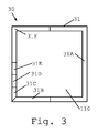
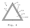
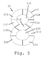
b)三角形、例えば、正方形、矩形、台形、若しくは平行四辺形である、四角形、五角形、六角形、七角形、八角形、十角形、九角形、十角形、十一角形、若しくは十二角形などの、規則的若しくは不規則的な多角形、又はその一部を形成する、並びに/あるいは、
c)ストライプの形状、及び/又は、細長い形状に概ね沿って配置された、別個の発光素子などの別個の要素、例えば、LED又は発光可能光ファイバーの一部の形状に延びる。
The peripheral illuminable device is generally along an elongated shape,
a) for example forming a curve such as one or more circles and / or ellipses, or a part thereof,
b) Triangles, for example, squares, rectangles, trapezoids, or parallelograms, squares, pentagons, hexagons, heptagons, octagons, decagons, octagons, decagons, ellipses, dodecagons, etc. Form a regular or irregular polygon, or part thereof, and / or
c) extends into the shape of a stripe and / or a separate element, such as a separate light emitting element, generally arranged along an elongated shape, eg, a portion of an LED or a light-emitting optical fiber.
制御装置は、ユーザに対して、
例えば、連続する部分、例えば、線状横並び構成の連続する部分を、内側部分を中心として、ある回転シーケンスで順次有効化するための設定、及び任意により、全ての部分を有効化した後に、全ての部分を同時に無効化する種類の設定など、上記の設定による、加熱器の起動などの起動手順の実行を示すように、
例えば、単一部分、又は隣接する部分のグループなどの、少なくとも1つの部分が順次有効化される設定など、上記の設定による、飲料調製の準備完了までに必要な時間に関する指標をインタフェースが提示するスタンバイ手順を示すように、
例えば、連続する部分を内側部分を中心に回転シーケンスで順次有効化し、かつ全ての部分が有効化された後に全ての部分を同時に無効化するか、又は部分を有効化しながら、先に有効化された部分を、回転シーケンスで順次無効化する設定など、上記の設定による、飲料調製手順、例えば、回転シーケンスが完了すると、これを一度以上繰り返すこのような上記の設定のような、例えば、遠心処理の軸線を取り囲む概ね外周の照明可能装置による、遠心処理による飲料調製手順の実行を示すように、
例えば、上記の設定、例えば、少なくとも1つの部分が順次有効化され、任意により全ての部分が順次有効化される設定による、ユーザ命令を受信する準備が完了した状態を示すように、
例えば、上記の設定、例えば、1つの部分が間欠的に有効化及び無効化される設定による、原材料カプセルなどのカプセルから、又は、例えば、ネットワーク又はポータブルメモリ装置に接続される、マシンインタフェースからの情報を読み取る手順の実行を示すように、
例えば、上記の設定、例えば、1つの部分が間欠的に有効化及び無効化される設定による、例えば、例えば水の不足などの原材料の不足を示す、エラーの状態を示すように、
例えば、上記の設定、例えば、少なくとも1つの部分が順次有効化される設定による、飲料調製プロセスのパラメータを設定するため、又はスタンバイ若しくは自動停止プロセスに入るためのタイマーを設定するためなどの、ユーザプログラミングモードの有効化を示すように、
例えば、上記の設定、例えば、全ての部分が有効化された後に全ての部分が同時に無効化されるか、若しくは先に有効化された部分が、回転シーケンスで順次無効化されるようにして、連続する部分が、内側部分を中心にして、回転シーケンスで順次有効化される設定、1つの部分が間欠的に有効化及び無効化される設定、又は少なくとも1つの部分が順次有効化される設定などによる、すすぎ、洗浄、スケール除去、又は水材料排出手順など、サービス手順の実行を示すように、並びに、
例えば、上記の設定、例えば、1つの部分が、間欠的に、例えば2回又は3回、有効化及び無効化される設定による、例えば、ユーザセレクタによる、ユーザ命令の獲得の完了を示すように、概ね外周の照明可能装置を制御するための1つ以上の設定を含み得る。
The control device
For example, after setting all parts to be enabled, after setting all parts in succession, for example, to set consecutive parts in a linear side-by-side configuration in a certain rotation sequence around the inner part. In order to show the execution of the start-up procedure such as starting the heater according to the above settings, such as the type setting to disable the part of
A standby where the interface presents an indication of the time required to be ready for beverage preparation according to the above settings, for example a setting in which at least one part is activated sequentially, such as a single part or a group of adjacent parts As shown in the procedure,
For example, enable successive parts sequentially in a rotation sequence around the inner part, and disable all parts simultaneously after all parts have been enabled, or enable them first while enabling parts. Beverage preparation procedures according to the above settings, such as settings for sequentially disabling the parts in the rotation sequence, for example, the centrifugal processing, such as the above settings that repeat this once or more once the rotation sequence is completed As shown to perform a beverage preparation procedure by centrifugation, with a generally perimeter illuminable device surrounding the axis of
For example, as shown in the above setting, e.g., a state in which at least one part is enabled sequentially and optionally all parts are sequentially enabled, ready to receive a user command,
For example, from a capsule such as a raw material capsule, with the above settings, e.g. settings where one part is enabled and disabled intermittently, or from a machine interface, e.g. connected to a network or portable memory device As shown in performing the steps to read the information,
For example, to indicate an error condition, e.g. indicating a lack of raw materials, e.g. a lack of water, e.g. due to the above setting, e.g. a setting where one part is enabled and disabled intermittently, e.g.
For example, to set the parameters of the beverage preparation process, or to set a timer for entering a standby or automatic stop process, according to the above settings, e.g. settings where at least one part is activated sequentially As shown to enable programming mode,
For example, the above settings, for example, all parts are validated after all parts are validated at the same time, or previously validated parts are sequentially invalidated in the rotation sequence, A setting in which consecutive parts are sequentially enabled in a rotation sequence around the inner part, a setting in which one part is enabled and disabled intermittently, or a setting in which at least one part is sequentially enabled To indicate the execution of service procedures such as rinsing, washing, descaling, or water material discharge procedures, etc., and
For example, to indicate completion of acquisition of a user command, for example, by a user selector, for example, with a setting that is enabled and disabled intermittently, eg 2 or 3 times, for example, one part May include one or more settings for controlling the generally perimeter illuminable device.
本発明はここで、概略図を参照して説明される。 The invention will now be described with reference to the schematic drawings.
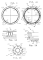
図1〜5は、本発明による飲料調製マシン1のための、異なるユーザインタフェース10、20、30、40、50を例示している。インタフェース10を備える飲料マシン1の実施例が図6に示される。
1 to 5 illustrate
代表的な飲料調製マシン1は、給水源2、及び飲料調製ユニット3を有し得る。給水源2は、水タンクであり得る。あるいは、マシンの給水源は、飲料マシンのいずれかの水タンクを手動で補充する必要がないように、都市の配水システムに直接接続することが可能なコネクタを含んでもよい。
A typical beverage preparation machine 1 may have a water supply 2 and a
マシン1は、熱い又は冷たい飲料を調製するように構成されてもよい。マシン1は、例えば、水及び/又はミルクなどの液体キャリア、及び1つ以上の香味料成分並びに/又は質感成分(texturing ingredient)、例えば、チョコレート、カカオ、コーヒー、茶、牛乳、シロップ、砂糖、クリーム、乳化剤、乾燥又はゲルスープなどの、異なる原材料を組み合わせるように構成され得る。原材料は、これを混合することにより、又は注入することにより、組み合わされ得る。好適なマシンは、例えば、国際公開第2009/074550号及び同第2009/130099号により詳細に開示されている。有利な実施形態において、飲料マシン1は、例えば、国際公開第2008/148601号、同第2008/148604号、同第2008/148646号、同第2008/148650号、同第2008/148656号、同第2009/106175号、同第2009/106598号、同第2010/063644号、同第2010/066736号、同第2010/089329号、同第2011/023711号、PCT/EP13/077276号、及びPCT/EP13/077275号に開示される、遠心処理により原材料を組み合わせるタイプのものである。したがって、マシン1は、内部に液体が注入され、原材料と液体とを混合するために、遠心軸3aを中心とした遠心処理を受ける、原材料カプセルを収容するための原材料混合チャンバ3b(典型的にはマシン1内に配置され、図6に点線で示される)を含む場合がある。原材料混合チャンバ3bは、(例えば、ハンドル1aを作動させることにより上部1aを旋回させるか、又は昇降させて)開閉することができ、回転させて原材料を混合することができる。
The machine 1 may be configured to prepare a hot or cold beverage. The machine 1 is for example a liquid carrier such as water and / or milk, and one or more flavoring ingredients and / or texturing ingredients such as chocolate, cacao, coffee, tea, milk, syrup, sugar, It can be configured to combine different ingredients, such as cream, emulsifier, dry or gel soup. The raw materials can be combined by mixing them or by pouring them. Suitable machines are disclosed in more detail, for example, in WO 2009/074550 and 2009/130099. In an advantageous embodiment, the beverage machine 1 is, for example, WO 2008/148601, 2008/148604, 2008/148646, 2008/148650, 2008/148656, No. 2009/106175, No. 2009/106598, No. 2010/063644, No. 2010/0666736, No. 2010/089329, No. 2011/023711, No. PCT / EP13 / 077776, and PCT / EP13 / 077275, which is a type of combining raw materials by centrifugation. Accordingly, the machine 1 has a raw
飲料マシン1は、典型的には、単一の出口、又は二重出口であり得る、出口3aを有する。出口3aは、注出領域4に飲料を供給するように構成され得る。注出領域4は、グラス、カップ、又はマグなどの容器を受容するように構成され得る。注出領域は、例えば欧州特許第1867260号、又は国際公開第2009/074557号に開示されるような、任意の種類のものであり得る。 The beverage machine 1 typically has an outlet 3a, which can be a single outlet or a double outlet. The outlet 3a may be configured to supply a beverage to the dispensing area 4. The dispensing area 4 can be configured to receive a container such as a glass, cup or mug. The dispensing area can be of any kind, for example as disclosed in EP 1867260 or WO 2009/074557.
飲料マシン1は、ユーザインタフェース10を含み、これは、図1、図1A、及び図1Bにより詳細に例示されている。あるいは、インタフェース10は、図1x〜5に例示されるインタフェース10’、20、30、40、50のいずれか、又は本発明の領域に包含される、そのバリエーションにより代替することができる。
The beverage machine 1 includes a
ユーザインタフェース10、10’、20、30、40、50は全て、
照明可能部分11A、11B、11C、11D、11E、11F、11A’、11B’、11C’、11D’、11E’、11F’、11G’、11H’、21A、21B、21C、21D、21E、21F、21G、31A、31B、31C、31D、31E、31F、41A、41B、51A、51B、51C、51D、51E、51F、51G、51H、51Xにより形成され、内側部分110、120の周囲で延びる、概ね外周の照明可能装置11、11’、21、31、41、51と、
プログラミング可能な制御装置などの、照明可能部分11A〜11F、11A’〜11H’、21A〜21G、31A〜31F、41A〜41B、51A〜51H、51Xの照明を有効化及び無効化するための制御装置100、105であって、例えば、プリント回路基板PCB100、及びPCBにコネクタ100’’’により接続されたコントローラなどのコントローラ105を備えたプログラミング可能な制御装置100、105とを有する。
The
Controls for enabling and disabling illumination of the
制御装置100、105は、飲料調製ユニット3のITモジュール、ポンプ、熱調節器、及び/又は動力部など、このようなマシン1の他の機能部を制御し得る。
The
典型的な実施形態において、ユーザインタフェース10、10’、20、30、40、50は、このようなマシン1の上部1a、前部1b、又は側部1cにある。図6において、例えば、ユーザインタフェース10は、マシン1の上部1aに設けられている。
In an exemplary embodiment, the
制御装置100、105は、照明可能部分11A〜11F、11A’〜11H’、21A〜21G、31A〜31F、41A〜41B、51A〜51H、51Xの一部のみを有効化するための、プログラミングされた設定などの少なくとも1つの設定を組み込んでもよい。
The
例えば、図1xに例示されるように、照明可能部分は、概ね外周の照明可能装置11’に沿って配置された、丸い又は多角形のスポットなど、1つ以上の照明可能スポット11A’〜11H’を含む場合がある。例えば、図1、2、3、4、及び5に例示されるように、照明可能部分は、概ね外周の照明可能装置11、21、31、41、51に沿って延びる1つ以上の細長いセグメント11A〜11F、21A〜21G、31A〜31F、41A〜41B、51A〜51H、51Xを有する場合がある。
For example, as illustrated in FIG. 1x, the illuminable portion may include one or more
このような細長いセグメントは、
円形セクター11A〜11Fに概ね沿って延びるセグメント(図1)、及び/又は楕円形セクター51A〜51Xに概ね沿って延びるセグメント(図6)などの、湾曲セグメント11A〜11F、51A〜51X、
真っ直ぐなセグメント21A、21C、21E、21F、21G、31B、21C、21D、21E(図2〜4)、
角度を成すセグメント21B、21D、31A、31G、41A、41B(図2〜4)、
外周の照明可能装置21、31、41の真っ直ぐな辺21A、21B、31A、41A、41B全体に沿って延びるセグメント(図2〜4)、
外周の照明可能装置21、31、41の、真っ直ぐな辺全体にわたって21B、31A、41A、41B、及び/若しくは真っ直ぐな辺の一部にわたって21D、31A、31F、41A、41B延びる、角度を成すセグメント、並びに/又は外周の照明可能装置21、31、41(図2〜4)の、2つの真っ直ぐな辺のみに沿って21B、21D、31F、41A、41B、及び/若しくは3つ以上の辺に沿って31A延びるセグメントなど、外周の照明可能装置21、31、41の複数の真っ直ぐな辺21B、31A、41A、41Bに沿って延びる、角度を成すセグメント、
外周の照明可能装置11、21、31、41、51の全長の部分にわたって延びるセグメントであって、各部分は、外周の照明可能装置の全長の、約半分である31A、41A、41B(図3及び図4)、又は1/3である21B(図2)、又は1/4である31F(図3)、又は1/5、又は1/6である11A〜11F、21A、21D(図1及び図2)、又は1/7、又は1/8である31B(図3)、又は1/9である51A〜51X(図5)、又は1/9、又は1/12である21C、21E、21F、21G(図2)、又は1/24である31C、31D、31E(図3)と対応する、セグメントと、並びに
これらの組み合わせ、例えば、異なる長さのセグメント(図2〜5)から、若しくは同じ長さのセグメント(図1)から作製される、及び/又は湾曲セグメント及び真っ直ぐなセグメントの組み合わせ(図示されない)から作製される、外周の照明可能装置であるセグメント、から選択され得る。
Such elongated segments are
A segment (FIGS. 2-4) extending along the entire
Angled segments extending 21B, 31A, 41A, 41B and / or 21D, 31A, 31F, 41A, 41B over part of the straight side of the outer
31A, 41A, 41B (FIG. 3), which are segments extending over the entire length of the peripheral
外周の照明可能装置11、11’、21、31、41、51は、単一の内側部分110(図1〜4)、又はいくつかの内側部分110、120の周辺に延びることがある。例えば、このような配置は、例えば、外周の照明可能装置51がほぼ8の形状になるように(図5)、一対の内側部分110、120の周囲で延びる。
The peripheral
単一の内側部分110は、いくつかの部分、例えば、複数の有効インタフェース部分110A、110B、110C、110D(図1及び図2)、複数の無効インタフェース部分、又は少なくとも1つの有効インタフェース部分110Eと少なくとも1つの無効インタフェース部分110Fとの組み合わせ(図4)から作製されることができ、例えば、有効インタフェース部分はユーザセレクタの形態であり、及び/又は無効ユーザインタフェース部分はハウジングの一部の形態である。
The single
内側部分は、例えば、セレクタ110E若しくは複数のセレクタ110A、110B、110C、110Dなどの、例えば、1つ以上のプッシュボタンの形態の、能動部分110、及び/又はハウジングの一部などの受動部分110F、120、から選択され得る。
The inner portion may be a
ユーザセレクタ110、110A、110B、110C、110D、110Eは典型的にはコントローラ105、又はPCB100に接続され、例えば、生成すべき、所望の量及び/又は濃度、及び/又は味などのいくつかの特徴を有する飲料の調製を開始するか、又は、例えば、すすぎ若しくは洗浄、若しくはスケール除去などサービス手順を実行するため、又はマシン1をオン若しくはオフにするため、又はユーザプログラミングモードに入るための命令などの、ユーザ命令を受信するように設定されてもよい。ユーザセレクタ110、110A、110B、110C、110D、110Eは、ユーザ命令のみを受けるように設定されてもよく、又はユーザに対して情報を示すように更に設定されてもよく、例えば、またユーザセレクタ自体がコントローラ105によって制御される発光装置を備えてもよい。例えば、ユーザセレクタは、セレクタと関連する機能部が、マシン1の使用時の所定の時点で利用可能であるかどうかによって、照明可能である。例えば、スケール除去プロセス中に飲料調製プロセスを開始することは不可能である。これは、対応するユーザセレクタの適切な照明によって示すことができる。これは、サービス手順中にはユーザが飲料を注文できないということを意味するものではなく、サービス手順が中断される必要があるか、又は最後まで実行されてから、飲料調製の命令を実行することを意味している。例えば、コントローラは、マシン1が、ユーザリクエストを実行可能な状態にある後の時点で実行するために、特定のユーザリクエストを記憶してもよい。例えば、記憶されたユーザリクエストを後で実行する実施例に関しては、例えば、国際公開第2011/020779号を参照せよ。当然、特定のプロセスを実行する入力を、このようなプロセスの実行が不可能であるかぎり、アクセプトしないように、マシンを設定することもまた可能である。
外周の照明可能装置11、11’、21、31、41、51は、以下の特徴:
発光素子101、102、103によって放出される光を拡散するための、半透明ウィンドなどの光拡散ウィンド111(図1、図1A、及び図2B)、
発光素子101’の形状をユーザに対して示すための、透明ウィンドなどの光透過ウィンド111’(図2x)、
単一の色の発光素子101’、又は、白色、黄色、橙色、赤色、緑色、青色、及びピンク色、並びにこれらの混合から選択される色など、異なる色の発光素子101、102、103(図1a、及び図1A)のグループ100A、100B、100C、100D、100E、100Fなどの異なる色の発光素子101、102、103を含む、複数の発光素子101、101’、102、103、
単一の色の発光素子101’によって、又は異なる色の発光素子101、102、104のグループ100A、100B、100C、100D、100E、100Fによって照明可能である、外周の照明可能装置11、11’、21、31、41、51の各照明可能部分11A〜11F、11A’〜11H’、21A〜21G、31A〜31F、41A〜41B、51A〜51H、51Xであって、このようなグループの発光素子は別個に又はグループで有効化可能である、各照明可能部分、並びに、
任意により、コネクタの対100’、100’’などのコネクタ100’、100’’(図1a、図1A及び図1B)により上記PCB又はあるPCB100に接続された、LEDなどの発光素子101’、101、102、103、の1つ以上を含んでもよい。
The peripheral
A light diffusion window 111 (FIGS. 1, 1A, and 2B), such as a translucent window, for diffusing the light emitted by the
A
A
Peripheral
Optionally, a
外周の照明可能装置11、11’、21、31、41、51の、照明可能部分11A〜11F、11A’〜11H’、21A〜21G、31A〜31F、41A〜41B、51A〜51H、51Xは、湾曲した構成(図1〜1x、及び図5)、及び/又は角度を成す線状構成(図2〜4)など、内側部分110、120の周囲で横並びの線状構成にあってもよい。このような照明可能部分は、
単一の横並び線状構成11A〜11F、11A’〜11H’、21A〜21G、31A〜31F、41A〜41B、51A〜51H、51X(図1〜5)、又は2つ、若3つ、若しくは4つのほぼ平行な横並び線状構成にある、及び/あるいは、
2つの隣接する照明可能部分が、互いに直接隣接している11A〜11F、11A’〜11H’、21A〜21G、31A〜31F、41A〜41B、51A〜51H、51X(図1、図2、図3、図4、及び図5)、又はハウジングの一部11aなどのスペーサによって離間している11A’〜11H’(図1x)、横並び線状構成11A〜11F、11A’〜11H’、21A〜21G、31A〜31F、41A〜41B、51A〜51H、51Xにあり得る。
Single side-by-side
11A to 11F, 11A ′ to 11H ′, 21A to 21G, 31A to 31F, 41A to 41B, 51A to 51H, 51X (FIGS. 1, 2 and FIG. 3, FIG. 4 and FIG. 5), or 11A ′ to 11H ′ (FIG. 1x) separated by spacers such as a portion 11a of the housing, side-by-side
照明部分11A〜11F、11A’〜11H’、21A〜21G、31A〜31F、41A〜41B、51A〜51H、51Xの照明は、実質的に、これらの部分全体にわたって広がり得る。任意により、このような部分11A〜11F、11A’〜11H’、21A〜21G、31A〜31F、41A〜41B、51A〜51H、51Xの照明は、これらの部分全体にわたって、ほぼ均一な光強度、及び/又は、白色、黄色、橙色、赤色、緑色、青色、及びピンク、又はいくつかのこのような色の混合から生じる色から選択される色などの、ほぼ均一な色をもたらす。
Illumination of the
制御装置100、105は、連続する部分11A〜11F、11A’〜11H’、21A〜21G、31A〜31F、41A〜41B、51A〜51H、51X、例えば、線状横並び構成の連続する部分を、内側部分110、120を中心として、ある回転シーケンスで順次有効化するための少なくとも1つの設定を有し得る。任意により、
a)時計方向及びその後の反時計方向のシーケンスで、又は、反時計方向及びその後の時計方向のシーケンスで順次有効化され、
b)回転シーケンスが完了すると、これを一度以上繰り返して順次有効化され、及び/又は、
c)回転シーケンスにわたって、及び/若しくは複数の連続する回転シーケンスの間で、
飲料調製手順、例えば、予備湿潤、及び抽出の連続する工程、及び/若しくは、
サービス手順、例えば、スケール除去手順の連続する工程、という異なる工程を示すように速度を変更し、順次有効化される。
The
a) sequentially enabled in a clockwise and subsequent counterclockwise sequence, or in a counterclockwise and subsequent clockwise sequence,
b) Once the rotation sequence is complete, this is repeated one or more times in order and / or
c) across the rotation sequence and / or between several consecutive rotation sequences
A sequence of beverage preparation procedures, eg pre-wetting and extraction, and / or
The speed is changed to indicate the different steps of the service procedure, for example, the successive steps of the descaling procedure, and are enabled sequentially.
このような設定は、例えば、起動サイクル、又は飲料調製サイクル、又は清掃サイクルなど、任意の時点におけるサイクルの動作を示すために使用され得る。有利な実施形態において、このような設定は、遠心処理による飲料調製サイクルを示すために使用されてもよく、外周の照明可能装置は、任意により遠心処理軸3aの周囲で延び、遠心処理は、遠心処理軸3aを中心とした遠心処理を示す、回転シーケンスの複数の繰り返しなどの回転シーケンスによって示される。 Such a setting can be used to indicate the operation of the cycle at any point in time, for example, a start-up cycle, or a beverage preparation cycle, or a cleaning cycle. In an advantageous embodiment, such a setting may be used to indicate a beverage preparation cycle by centrifugation, the peripheral illuminable device optionally extends around the centrifuge axis 3a, This is indicated by a rotation sequence such as a plurality of repetitions of the rotation sequence, which indicates a centrifugal process centered on the centrifugal processing shaft 3a.
制御装置100、105は、連続する部分11A〜11F、11A’〜11H’、21A〜21G、31A〜31F、41A〜41B、51A〜51H、51Xを、内側部分110、120を中心として回転シーケンスで順次有効化し、全ての部分を有効化した後に、全ての部分を同時に無効化するための、少なくとも1つの設定を有し得る。
The
制御装置100、105は、連続する部分11A〜11F、11A’〜11H’、21A〜21G、31A〜31F、41A〜41B、51A〜51H、51Xを、内側部分110、120を中心として回転シーケンスで順次有効化しながら、前に有効化させた部分を回転シーケンスで順次無効化するための、少なくとも1つの設定を有し得る。部分は、等しい有効化速度及び無効化速度、又は、無効化速度よりも速い有効化速度などの、異なる有効化速度及び無効化速度を有し得る。少なくとも2つ又は3つの部分が同時に有効化状態になり得る。
The
制御装置100、105は、1つの部分、11A〜11F、11A’〜11H’、21A〜21G、31A〜31F、41A〜41B、51A〜51H、51Xが、間欠的に有効化及び無効化される、少なくとも1つの設定を有し得る。
In the
例えば、このような設定は、エラーの表示、又は、ユーザセレクタによりユーザ命令が適切に獲得されたことを確認するなどの、マシン1が情報を獲得したことを確認する表示と関連付けられ得る。 For example, such a setting may be associated with an indication of an error or a confirmation that the machine 1 has acquired information, such as confirming that a user command has been properly acquired by a user selector.
複数のこのような部分11A〜11F、11A’〜11H’、21A〜21G、31A〜31F、41A〜41B、51A〜51H、51Xは、同時に有効化及び無効化されてもよい。例えば、複数の部分、又は部分のグループが、内側部分110、120を中心に他の恒久的に有効化又は無効化された部分により離間している。このような部品、又は部品のグループは、例えば、内側部分110、120を中心に均等に離間している。
A plurality of
このような部分11A〜11F、11A’〜11H’、21A〜21G、31A〜31F、41A〜41B、51A〜51H、51Xの2つが、交互に有効化及び無効化され得る。
Two
例えば、2つの部分が、交互に有効化及び無効化される。 For example, the two parts are enabled and disabled alternately.
例えば、このような設定は、例えば、ユーザセレクタによるユーザ入力、又はユーザによる別のアクションのマシン1による期待値と関連付けられ得る。 For example, such a setting may be associated with, for example, a user input by a user selector or an expected value by the machine 1 for another action by the user.
このような部分11A〜11F、11A’〜11H’、21A〜21G、31A〜31F、41A〜41B、51A〜51H、51Xが、一定の頻度で間欠的に有効化及び無効化され得る。例えば、いくつかの部分が、一定の頻度で間欠的に有効化及び無効化される。
このような設定に加えて、制御装置100、105は、上記の設定よりも速い速度で、部分11A〜11F、11A’〜11H’、21A〜21G、31A〜31F、41A〜41B、51A〜51H、51Xを有効化及び無効化するための少なくとも1つの他の設定を有し得る。
In addition to such a setting, the
例えば、異なる種類の手順の実行を区別するために、異なる速度が使用されてもよい。例えば、起動又はサービス(例えば、スケール除去)手順の実行が、比較的遅い速度における1つ以上の回転シーケンスによって示されてもよく、飲料調製手順は、比較的速い速度における1つ以上の回転シーケンスによって示されてもよい。 For example, different speeds may be used to distinguish between performing different types of procedures. For example, execution of a start-up or service (eg, descaling) procedure may be indicated by one or more rotation sequences at a relatively slow speed, and a beverage preparation procedure may include one or more rotation sequences at a relatively high speed. May be indicated by
例えば、異なる速度は、例えば、ルンゴ若しくはエスプレッソコーヒーの異なる飲料の調製手順などの同じ種類の異なる手順、又は軽度の若しくは集中的スケール除去手順などの異なるサービス手順実行を区別するために、実施され得る。 For example, different rates may be implemented to differentiate between different procedures of the same type, such as, for example, preparation procedures for different beverages of Lungo or Espresso coffee, or different service procedures, such as mild or intensive descaling procedures. .
有効化可能及び無効化可能な部分に加えて、少なくとも1つの部分が、上記の設定又は上記の更なる設定において、恒久的に有効化又は無効化されたままであってもよい。 In addition to the enableable and disableable parts, at least one part may remain permanently enabled or disabled in the above settings or in the further settings.
例えば、原材料(例えば、水)利用可能性が最低レベルに近づいているなど、非停止警告が、恒久的有効部分によって示されてもよい。非停止警告の別の例は、短い時間内にサービス(例えば、スケール除去)プロセスを行うことの必要性に関連し得る。 For example, a non-stop warning may be indicated by a permanently active portion, such as raw material (eg, water) availability is approaching a minimum level. Another example of a non-stop alert may relate to the need to perform a service (eg, descaling) process in a short time.
制御装置100、105は、例えば、単一部分11A〜11F、11A’〜11H’、21A〜21G、31A〜31F、41A〜41B、51A〜51H、51X、又は隣接する部分のグループなどの、少なくとも1つの部分が順次有効化される、少なくとも1つの設定を有し得る。
The
外周の照明可能装置11、11’、21、31、41、51は、細長い形状に概ね沿っており、
a)例えば、1つ以上の円11、11’(図1、図1a、及び図1x)及び/若しくは楕円51(図5)、又はその一部などの曲線11,11’を形成する、
b)三角形41(図4)、例えば、正方形31(図3)、矩形、台形、若しくは平行四辺形である、四角形31、五角形、六角形21(図2)、七角形、八角形11’(図1x)、十角形、九角形、十角形、十一角形、若しくは十二角形などの、規則的若しくは不規則的な多角形21、31、41、又はその一部を形成する、
c)ストライプ11、21、31、41、51(図1、図2〜5)の形状、及び/又は細長い形状に概ね沿って配置された、別個の発光素子などの別個の要素11’(図1x)、例えば、LED101’又は発光可能光ファイバーの一部の形状に延びる、あるいは、
d)湾曲部分、及び真っ直ぐ若しくは角度を成す部分から形成された外周の照明可能装置などの、特徴a)、b)、及びc)の少なくとも2つの組み合わせである。
The peripheral
a) for example forming one or
b) Triangle 41 (FIG. 4), for example, square 31 (FIG. 3), rectangle, trapezoid, or parallelogram, quadrilateral 31, pentagon, hexagon 21 (FIG. 2), heptagon,
c)
d) A combination of at least two of features a), b), and c), such as an outer illuminable device formed from a curved portion and a straight or angled portion.
制御装置100、105は、ユーザに対して、
例えば、連続する部分、例えば、線状横並び構成の連続する部分を、内側部分を中心として、ある回転シーケンスで順次有効化するための設定、及び任意により、全ての部分を有効化した後に、全ての部分を同時に無効化する種類の設定など、上記の設定による、加熱器の起動などの起動手順の実行を示すように、
例えば、単一部分、又は隣接する部分のグループなどの、少なくとも1つの部分が順次有効化される設定など、上記の設定による、飲料調製の準備完了までに必要な時間に関する指標をインタフェースが提示するスタンバイ手順を示すように、
例えば、連続する部分を内側部分を中心に回転シーケンスで順次有効化し、かつ全ての部分が有効化された後に全ての部分を同時に無効化するか、又は先に有効化された部分を、回転シーケンスで順次無効化する設定など、上記の設定による、飲料調製手順、例えば、回転シーケンスが完了すると、これを一度以上繰り返すこのような上記の設定のような、例えば、遠心処理の軸線を取り囲む概ね外周の照明可能装置による、遠心処理による飲料調製手順の実行を示すように、
例えば、上記の設定、例えば、少なくとも1つの部分が順次有効化され、任意により全ての部分が順次有効化される設定による、ユーザ命令を受信する準備が完了した状態を示すように、
例えば、上記の設定、例えば、1つの部分が間欠的に有効化及び無効化される設定による、原材料カプセルなどのカプセルから、又は、例えば、ネットワーク又はポータブルメモリ装置に接続される、マシンインタフェースからの情報を読み取る手順の実行を示すように、
例えば、上記の設定、例えば、1つの部分が間欠的に有効化及び無効化される設定による、例えば、例えば水の不足などの原材料の不足を示す、エラーの状態を示すように、
例えば、上記の設定、例えば、少なくとも1つの部分が順次有効化される設定による、飲料調製プロセスのパラメータを設定するため、又はスタンバイ若しくは自動停止プロセスに入るためのタイマーを設定するためなどの、ユーザプログラミングモードの有効化を示すように、
例えば、上記の設定成、例えば、全ての部分が有効化された後に全ての部分が同時に無効化されるか、若しくは先に有効化された部分が、回転シーケンスで順次無効化されるようにして、連続する部分が、内側部分を中心にして、回転シーケンスで順次有効化される設定、1つの部分が間欠的に有効化及び無効化される設定、又は少なくとも1つの部分が順次有効化される設定などによる、すすぎ、洗浄、スケール除去、又は水材料排出手順など、サービス手順の実行を示すように、並びに、
例えば、上記の設定、例えば、1つの部分11A〜11F、11A’〜11H’、21A〜21G、31A〜31F、41A〜41B、51A〜51H、51Xが、間欠的に、例えば2回又は3回、有効化及び無効化される設定による、例えば、ユーザセレクタ110、110A、110B、110C、110Dによる、ユーザ命令の獲得の完了を示すように、概ね外周の照明可能装置11、11’、21、31、41、51を制御するための1つ以上の設定を含み得る。
The
For example, after setting all parts to be enabled, after setting all parts in succession, for example, to set consecutive parts in a linear side-by-side configuration in a certain rotation sequence around the inner part. In order to show the execution of the start-up procedure such as starting the heater according to the above settings, such as the type setting to disable the part of
A standby where the interface presents an indication of the time required to be ready for beverage preparation according to the above settings, for example a setting in which at least one part is activated sequentially, such as a single part or a group of adjacent parts As shown in the procedure,
For example, enable consecutive parts sequentially around the inner part in a rotation sequence and disable all parts at the same time after all parts have been enabled, or turn previously activated parts into a rotation sequence. When the beverage preparation procedure according to the above settings, such as the setting to be sequentially disabled, for example, the rotation sequence is completed, this is repeated one or more times. As shown to demonstrate the execution of the beverage preparation procedure by centrifugation with the illuminable device of
For example, as shown in the above setting, e.g., a state in which at least one part is enabled sequentially and optionally all parts are sequentially enabled, ready to receive a user command,
For example, from a capsule such as a raw material capsule, with the above settings, e.g. settings where one part is enabled and disabled intermittently, or from a machine interface, e.g. connected to a network or portable memory device As shown in performing the steps to read the information,
For example, to indicate an error condition, e.g. indicating a lack of raw materials, e.g. a lack of water, e.g. due to the above setting, e.g. a setting where one part is enabled and disabled intermittently, e.g.
For example, to set the parameters of the beverage preparation process, or to set a timer for entering a standby or automatic stop process, according to the above settings, e.g. settings where at least one part is activated sequentially As shown to enable programming mode,
For example, the above settings are made, for example, all parts are validated at the same time after all parts are validated, or the parts that have been validated earlier are sequentially invalidated in the rotation sequence. A setting where successive parts are enabled sequentially in the rotation sequence around the inner part, a setting where one part is enabled and disabled intermittently, or at least one part is sequentially enabled To indicate the execution of a service procedure, such as a rinse, wash, descaling, or water material discharge procedure, such as by setting, and
For example, the above setting, for example, one
Claims (16)
照明可能部分(11A、11B、11C、11D、11E、11F、11A’、11B’、11C’、11D’、11E’、11F’、11G’、11H’、21A、21B、21C、21D、21E、21F、21G、31A、31B、31C、31D、31E、31F、41A、41B、51A、51B、51C、51D、51E、51F、51G、51H、51X)により形成され、内側部分(110、120)の周囲で延びる、概ね外周の照明可能装置(11、11’、21、31、41、51)と、
プログラミング可能な制御装置(100、105)などの、前記照明可能部分の照明を有効化及び無効化するための制御装置(100、105)であって、例えば、プリント回路基板PCB(100)、及び該PCBにコネクタ(100’’’)により接続されたコントローラ(105)を備え、任意により、飲料調製ユニット(3)のITモジュール、ポンプ、熱調節器、及び/又は動力部など、前記マシン(1)の他の機能部を制御する、制御装置と、を有するユーザインタフェース(10、10’、20、30、40、50)を備え、
前記ユーザインタフェース(10、10’、20、30、40、50)は、任意により、前記マシン(1)の上部(1a)、前部(1b)、又は側部(1c)にある、飲料調製マシンにおいて、
前記制御装置(100、105)は、前記照明可能部分(11A〜11F、11A’〜11H’、21A〜21G、31A〜31F、41A〜41B、51A〜51H、51X)の一部のみを有効化するための、プログラミングされた設定などの少なくとも1つの設定を有することを特徴とする、飲料調製マシン(1)。 A beverage preparation machine (1), such as a machine having a water supply (2), a beverage preparation unit (3), and an outlet (3a) for supplying beverage to a beverage dispensing area (4),
Illuminable parts (11A, 11B, 11C, 11D, 11E, 11F, 11A ′, 11B ′, 11C ′, 11D ′, 11E ′, 11F ′, 11G ′, 11H ′, 21A, 21B, 21C, 21D, 21E, 21F, 21G, 31A, 31B, 31C, 31D, 31E, 31F, 41A, 41B, 51A, 51B, 51C, 51D, 51E, 51F, 51G, 51H, 51X), and the inner portion (110, 120) A peripherally illuminable device (11, 11 ′, 21, 31, 41, 51) extending around,
A controller (100, 105) for enabling and disabling illumination of the illuminable part, such as a programmable controller (100, 105), for example, a printed circuit board PCB (100), and The machine (105) comprising a controller (105) connected to the PCB by a connector (100 ″ ′), optionally an IT module, pump, heat regulator and / or power unit of the beverage preparation unit (3) 1) a user interface (10, 10 ′, 20, 30, 40, 50) having a control device for controlling other functional units;
The user interface (10, 10 ', 20, 30, 40, 50) is optionally at the top (1a), front (1b) or side (1c) of the machine (1), beverage preparation In the machine
The control device (100, 105) activates only a part of the illuminable parts (11A-11F, 11A′-11H ′, 21A-21G, 31A-31F, 41A-41B, 51A-51H, 51X). Beverage preparation machine (1), characterized in that it has at least one setting, such as a programmed setting for
円形セクターに概ね沿って延びるセグメント(11A〜11F)、及び/又は楕円形セクターに概ね沿って延びるセグメント(51A〜51X)などの、湾曲セグメント(11A〜11F、51A〜51X)、
真っ直ぐなセグメント(21A、21C、21E、21F、21G、31B、21C、21D、21E)、
角度を成すセグメント(21B、21D、31A、31G、41A、41B)、
前記外周の照明可能装置(21、31、41)の真っ直ぐな辺(21A、21B、31A、41A、41B)全体に沿って延びるセグメント、
前記外周の照明可能装置(21、31、41)の、真っ直ぐな辺全体にわたって(21B、31A、41A、41B)、及び/若しくは真っ直ぐな辺の一部にわたって(21D、31A、31F、41A、41B)延びる、角度を成すセグメント、並びに/又は前記外周の照明可能装置(21、31、41)の、2つの真っ直ぐな辺のみに沿って(21B、21D、31F、41A、41B)、及び/若しくは3つ以上の辺に沿って(31A)延びるセグメントなど、前記外周の照明可能装置(21、31、41)の複数の真っ直ぐな辺(21B、31A、41A、41B)に沿って延びる、角度を成すセグメント、並びに、
前記外周の照明可能装置(11、21、31、41、51)の全長の部分にわたって延びるセグメントであって、この部分は全長(31C、31D、31E)の約半分(31A、41A、41B)、又は1/3(21B)、又は1/4(31F)、又は1/5、又は1/6(11A〜11F、21A、21D)、又は1/7、又は1/8(31B)、又は1/9(51A〜51X)、又は1/10、又は1/12(21C、21E、21F、21G)、又は1/24と対応する、セグメント、から選択され得るセグメントを含む、請求項1に記載のマシン。 The illuminable portions (11A to 11F, 11A ′ to 11H ′, 21A to 21G, 31A to 31F, 41A to 41B, 51A to 51H, 51X) are arranged along the substantially outer illuminable device (11 ′). Round spot or one or more spots (11A′-11H ′) such as a polygonal spot, such as a triangular, square, pentagonal, or octagonal spot, and / or said generally perimeter Having one or more elongated segments extending along the illuminable device (11, 21, 31, 41, 51), said elongated segments comprising:
Curved segments (11A-11F, 51A-51X), such as segments (11A-11F) extending generally along a circular sector and / or segments (51A-51X) extending generally along an elliptical sector,
Straight segments (21A, 21C, 21E, 21F, 21G, 31B, 21C, 21D, 21E),
Angled segments (21B, 21D, 31A, 31G, 41A, 41B),
A segment extending along the entire straight side (21A, 21B, 31A, 41A, 41B) of the peripheral illuminable device (21, 31, 41);
Over the entire straight side (21B, 31A, 41A, 41B) and / or over a part of the straight side of the outer illuminable device (21, 31, 41) (21D, 31A, 31F, 41A, 41B). ) Extending the angled segment and / or along only two straight sides (21B, 21D, 31F, 41A, 41B) of the peripheral illuminable device (21, 31, 41) and / or An angle extending along a plurality of straight sides (21B, 31A, 41A, 41B) of the peripheral illuminable device (21, 31, 41), such as a segment extending (31A) along three or more sides. Segments, and
A segment extending over the entire length of the outer peripheral illuminable device (11, 21, 31, 41, 51), which is about half of the total length (31C, 31D, 31E) (31A, 41A, 41B), Or 1/3 (21B), or 1/4 (31F), or 1/5, or 1/6 (11A-11F, 21A, 21D), or 1/7, or 1/8 (31B), or 1 2. A segment that may be selected from: a segment corresponding to 1/9 (51A-51X), or 1/10, or 1/12 (21C, 21E, 21F, 21G), or 1/24. Machine of.
発光素子(101、102、103)によって放出される光を拡散するための、半透明ウィンドなどの光拡散ウィンド(111)、
前記発光素子(101’)の形状をユーザに対して示すための、透明ウィンドなどの光透過ウィンド(111’)、
単一の色の発光素子(101’)、又は、白色、黄色、橙色、赤色、緑色、青色、及びピンク色、並びにこれらの混合から選択される色など、異なる色の発光素子(101、102、103)のグループ(100A、100B、100C、100D、100E、100F)などの異なる色の発光素子(101、102、103)を含む、複数の発光素子(101、101’、102、103)、
単一の色の発光素子(101’)によって、又は異なる色の発光素子(101、102、103)のグループ(100A、100B、100C、100D、100E、100F)によって照明可能である、前記外周の照明可能装置(11、11’、21、31、41、51)の各照明可能部分(11A〜11F、11A’〜11H’、21A〜21G、31A〜31F、41A〜41B、51A〜51H、51X)であって、前記グループの前記発光素子は別個に又はグループで有効化可能である、各照明可能部分、並びに、
任意により、コネクタの対(100’、100’’)などのコネクタ(100’、100’’)により前記PCB又はあるPCB100に接続された、LEDなどの発光素子(101’、101、102、103)、の1つ以上を含む、請求項1〜4のいずれか一項に記載のマシン。 The generally peripheral illuminable device (11, 11 ′, 21, 31, 41, 51) has the following characteristics:
A light diffusion window (111), such as a translucent window, for diffusing the light emitted by the light emitting elements (101, 102, 103);
A light transmitting window (111 ′) such as a transparent window for indicating to the user the shape of the light emitting element (101 ′);
A single color light emitting element (101 ′) or different color light emitting elements (101, 102) such as white, yellow, orange, red, green, blue, and pink, and a color selected from a mixture thereof. , 103) including a plurality of light emitting elements (101, 101 ′, 102, 103), including light emitting elements (101, 102, 103) of different colors such as a group (100A, 100B, 100C, 100D, 100E, 100F),
Of the outer periphery, which can be illuminated by a single color light emitting element (101 ') or by a group (100A, 100B, 100C, 100D, 100E, 100F) of light emitting elements (101, 102, 103) of different colors Each illuminable part (11A-11F, 11A'-11H ', 21A-21G, 31A-31F, 41A-41B, 51A-51H, 51X of the illuminable device (11, 11', 21, 31, 41, 51) Each illuminable portion, wherein the light emitting elements of the group can be activated separately or in groups, and
Optionally, light emitting elements (101 ′, 101, 102, 103) such as LEDs connected to the PCB or a PCB 100 by connectors (100 ′, 100 ″) such as connector pairs (100 ′, 100 ″). The machine according to claim 1, comprising one or more of:
単一の横並び線状構成(11A〜11F、11A’〜11H’、21A〜21G、31A〜31F、41A〜41B、51A〜51H、51X)、又は2つ、3つ、若しくは4つのほぼ平行な若しくは同心状の横並び線状構成にある、並びに/あるいは、
2つの隣接する照明可能部分が、互いに直接隣接している(11A〜11F、21A〜21G、31A〜31F、41A〜41B、51A〜51H、51X)、又はハウジングの一部(11a)などのスペーサによって離間している(11A’〜11H’)、横並び線状構成(11A〜11F、11A’〜11H’、21A〜21G、31A〜31F、41A〜41B、51A〜51H、51X)にある、請求項1〜5のいずれか一項に記載のマシン。 The illuminable portions (11A to 11F, 11A ′ to 11H ′, 21A to 21G, 31A to 31F, 41A to 41B, 51A of the generally illuminable device (11, 11 ′, 21, 31, 41, 51). ˜51H, 51X) are in a linear configuration side by side around the inner portion (110, 120), such as a curved and / or angled linear configuration, optionally, of the generally perimeter illuminable device. The illuminable part is
Single side-by-side linear configuration (11A-11F, 11A′-11H ′, 21A-21G, 31A-31F, 41A-41B, 51A-51H, 51X), or two, three, or four nearly parallel Or a concentric side-by-side linear configuration and / or
Two adjacent illuminable parts are directly adjacent to each other (11A-11F, 21A-21G, 31A-31F, 41A-41B, 51A-51H, 51X), or a spacer such as part of the housing (11a) (11A ′ to 11H ′), which are separated from each other by a side-by-side linear configuration (11A to 11F, 11A ′ to 11H ′, 21A to 21G, 31A to 31F, 41A to 41B, 51A to 51H, 51X), Item 6. The machine according to any one of Items 1 to 5.
a)時計方向及びその後の反時計方向の回転シーケンスで、又は、反時計方向及びその後の時計方向の回転シーケンスで順次有効化するための少なくとも1つの設定、
b)前記回転シーケンスが完了すると、これを一度以上繰り返して順次有効化するための少なくとも1つの設定、
c)回転シーケンスにわたって、及び/若しくは複数の連続する回転シーケンスの間で、例えば、
飲料調製手順、例えば、予備湿潤、及び抽出の連続する工程、及び/若しくは、
サービス手順、例えば、スケール除去手順の連続する工程、という異なる工程を示すように速度を変更し、順次有効化するための少なくとも1つの設定、
あるいは、
d)特徴a)〜c)の少なくとも2つの組み合わせを有する、請求項1〜7のいずれか一項に記載のマシン。 The control device (100, 105) includes continuous portions (11A to 11F, 11A ′ to 11H ′, 21A to 21G, 31A to 31F, 41A to 41B, 51A to 51H, 51X), for example, in a linear side-by-side configuration. Having at least one setting for sequentially enabling a continuous part in a rotation sequence around the inner part (110, 120), optionally,
a) at least one setting for sequentially enabling in a clockwise and subsequent counterclockwise rotation sequence or in a counterclockwise and subsequent clockwise rotation sequence;
b) when the rotation sequence is completed, at least one setting for sequentially enabling the rotation sequence one or more times,
c) over a rotation sequence and / or between a plurality of consecutive rotation sequences, for example
A sequence of beverage preparation procedures, eg pre-wetting and extraction, and / or
At least one setting to change the speed to indicate different steps of service procedures, e.g. successive steps of the descaling procedure, and to enable them sequentially,
Or
d) Machine according to any one of the preceding claims, having a combination of at least two of features a) to c).
a)前記部分は、等しい有効化速度及び無効化速度、又は、前記無効化速度よりも速い有効化速度などの、異なる有効化速度及び無効化速度を有する、及び/若しくは、
b)少なくとも2つ又は3つの部分が同時に有効化状態になる、少なくとも1つの設定を有する、請求項8又は9に記載のマシン。 The control device (100, 105) includes the continuous portion (11A to 11F, 11A ′ to 11H ′, 21A to 21G, 31A to 31F, 41A to 41B, 51A to 51H, 51X) as the inner portion (110). , 120) around the rotation sequence in turn, while invalidating the previously activated portions in the rotation sequence, optionally,
a) the portions have different activation rates and invalidation rates, such as equal activation rate and invalidation rate, or an activation rate faster than the invalidation rate, and / or
10. A machine according to claim 8 or 9, having at least one setting, wherein b) at least two or three parts are activated at the same time.
a)前記内側部分(110、120)を中心に恒久的に有効化又は無効化された部分によって離間した、例えば、ほぼ均等に離間した、複数の部分又は部分のグループなどの複数の前記部分(11A〜11F、11A’〜11H’、21A〜21G、31A〜31F、41A〜41B、51A〜51H、51X)が、同時に有効化及び無効化される、
b)複数の2つの部分が交互に有効化及び無効化されるなど、前記部分(11A〜11F、11A’〜11H’、21A〜21G、31A〜31F、41A〜41B、51A〜51H、51X)の2つが、交互に有効化及び無効化される、
c)前記部分(11A〜11F、11A’〜11H’、21A〜21G、31A〜31F、41A〜41B、51A〜51H、51X)は、一定の頻度で間欠的に有効化及び無効化され、例えば、いくつかの部分が一定の頻度で間欠的に有効化及び無化される、又は
d)特徴a)、b)、及びc)の2つ又は3つの組み合わせである、請求項1〜10のいずれか一項に記載のマシン。 As for the said control apparatus (100,105), one part (11A-11F, 11A'-11H ', 21A-21G, 31A-31F, 41A-41B, 51A-51H, 51X) is intermittently enabled and disabled. Has at least one setting, optionally,
a) a plurality of said parts, such as a plurality of parts or groups of parts, separated by, for example, parts that are permanently activated or deactivated around said inner part (110, 120), for example substantially evenly spaced; 11A-11F, 11A′-11H ′, 21A-21G, 31A-31F, 41A-41B, 51A-51H, 51X) are simultaneously enabled and disabled,
b) Said part (11A-11F, 11A'-11H ', 21A-21G, 31A-31F, 41A-41B, 51A-51H, 51X), such as a plurality of two parts being alternately enabled and disabled Are alternately enabled and disabled,
c) The parts (11A-11F, 11A′-11H ′, 21A-21G, 31A-31F, 41A-41B, 51A-51H, 51X) are enabled and disabled intermittently with a certain frequency, for example 11. Some parts are enabled and disabled intermittently at a constant frequency, or d) a combination of two or three of features a), b), and c) The machine according to any one of the above.
起動若しくはサービス(例えば、スケール除去)手順の実行など、異なる種類の手順の実行を区別するための少なくとも1つの更なる設定、及び/又は、
例えば、ルンゴ若しくはエスプレッソコーヒーの異なる飲料の調製手順などの同じ種類の異なる手順、又は、例えば、軽度の若しくは集中的スケール除去手順などの異なるサービス手順の実行を区別するための少なくとも1つの更なる設定を有する、請求項8〜11のいずれか一項に記載のマシン。 In addition to the setting, the control device (100, 105) is configured to perform the parts (11A-11F, 11A'-11H ', 21A-21G, 31A-31F, 41A-41B, 51A- 51H, 51X) is enabled and disabled, for example,
At least one additional setting to distinguish between execution of different types of procedures, such as execution or execution of a service (eg descaling) procedure, and / or
At least one further setting to distinguish between performing different procedures of the same type, such as, for example, different beverage preparation procedures of Lungo or espresso coffee, or different service procedures, such as, for example, mild or intensive descaling procedures The machine according to any one of claims 8 to 11, which has
a)例えば、1つ以上の円(11、11’)及び/若しくは楕円(51)、又はその一部などの曲線(11、11’)を形成する、
b)三角形(41)、例えば、正方形(31)、矩形、台形、若しくは平行四辺形である、四角形(31)、五角形、六角形(21)、七角形、八角形(11’)、九角形、十角形、十一角形、若しくは十二角形などの、規則的若しくは不規則的な多角形(21、31、41)、又はその一部を形成する、
c)ストライプ(11、21、31、41、51)の形状、及び/又は、前記細長い形状に概ね沿って配置された、別個の発光素子などの別個の要素(11’)、例えば、LED(101’)又は発光可能光ファイバーの一部の形状に延びる、あるいは、
d)特徴a)、b)、及びc)の少なくとも2つの組み合わせである、請求項1〜14のいずれか一項に記載のマシン。 The peripheral illuminable devices (11, 11 ′, 21, 31, 41, 51) are generally along an elongated shape,
a) for example forming a curve (11, 11 ′) such as one or more circles (11, 11 ′) and / or an ellipse (51), or part thereof,
b) Triangle (41), for example, square (31), rectangle, trapezoid or parallelogram, quadrangle (31), pentagon, hexagon (21), heptagon, octagon (11 '), nine-sided Form a regular or irregular polygon (21, 31, 41), or a part thereof, such as a decagon, an eleven, or a dodecagon,
c) The shape of the stripe (11, 21, 31, 41, 51) and / or a separate element (11 ′), such as a separate light emitting element, arranged generally along said elongated shape, eg LED ( 101 ') or extending in the shape of a part of the light-emitting optical fiber, or
d) Machine according to any one of the preceding claims, which is a combination of at least two of features a), b) and c).
例えば、請求項8又は9に定義される設定による、加熱器の起動などの起動手順の実行を示すように、
例えば、請求項14に定義される設定による、飲料調製の準備完了までに必要な時間に関する指標をインタフェースが提示するスタンバイ手順を示すように、
例えば、請求項8、9、又は10に定義される設定による、飲料調製手順、例えば、請求項8の選択肢b)と組み合わされた請求項10など、請求項10に定義される設定による、例えば、遠心処理の軸線(3a)を取り囲む前記概ね外周の照明可能装置(11、11’、21、31、41、51)による、遠心処理による飲料調製手順の実行を示すように、
例えば、請求項14に定義される設定による、任意により、全ての前記部分が有効化されている(11A〜11F、11A’〜11H’、21A〜21G、31A〜31F、41A〜41B、51A〜51H、51X)、ユーザ命令を受信する準備が完了した状態を示すように、
例えば、請求項11に記載される設定による、原材料カプセルなどのカプセルから、又は、例えば、ネットワーク又はポータブルメモリ装置に接続される、マシンインタフェースからの情報を読み取る手順の実行を示すように、
例えば、請求項11に定義される設定による、例えば、水の不足などの原材料の不足を示す、エラーの状態を示すように、
例えば、請求項14に定義される設定による、飲料調製プロセスのパラメータを設定するため、又はスタンバイ若しくは自動停止プロセスに入るためのタイマーを設定するためなどの、ユーザプログラミングモードの有効化を示すように、
例えば、請求項8〜14のいずれか一項に定義される設定による、すすぎ、洗浄、スケール除去、又は水材料排出手順など、サービス手順の実行を示すように、かつ、
例えば、請求項11に定義される設定による、例えば、少なくとも1つの部分(11A〜11F、11A’〜11H’、21A〜21G、31A〜31F、41A〜41B、51A〜51H、51X)の有効化及び無効化シーケンスのいくつかにより、例えば、ユーザセレクタ(110、110A、110B、110C、110D)による、ユーザ命令の獲得の完了を示すように、
前記概ね外周の照明可能装置(11、11’、21、31、41、51)を制御するための1つ以上の設定を含む、請求項1〜15のいずれか一項に記載のマシン。 The control device (100, 105)
For example, to indicate the execution of a start-up procedure, such as starting a heater, according to the settings defined in claim 8 or 9
For example, to indicate a standby procedure in which the interface presents an indication of the time required to be ready for beverage preparation according to the settings defined in claim 14
For example, according to the settings defined in claim 10, such as claim 10 in combination with a beverage preparation procedure, eg option b) of claim 8, according to the settings defined in claim 8, 9, or 10. As shown in the execution of the beverage preparation procedure by centrifugation, by means of the generally peripheral illuminable device (11, 11 ′, 21, 31, 41, 51) surrounding the axis of centrifugation (3a),
For example, according to the settings defined in claim 14, all the parts are optionally activated (11A-11F, 11A′-11H ′, 21A-21G, 31A-31F, 41A-41B, 51A˜ 51H, 51X), indicating that the preparation for receiving the user command is complete,
As shown, for example, according to the setting according to claim 11 from performing a procedure for reading information from a capsule, such as a raw material capsule, or from a machine interface connected to a network or portable memory device, for example.
For example, according to the settings defined in claim 11, to indicate an error condition, for example indicating a lack of raw materials such as a lack of water,
To indicate the activation of a user programming mode, for example to set the parameters of the beverage preparation process, or to set a timer to enter the standby or automatic stop process, according to the settings defined in claim 14 ,
To indicate the execution of a service procedure, such as a rinse, wash, descaling or water material discharge procedure according to the settings defined in any one of claims 8-14, and
For example, activation of at least one part (11A-11F, 11A′-11H ′, 21A-21G, 31A-31F, 41A-41B, 51A-51H, 51X), for example, according to the settings defined in claim 11 And some of the invalidation sequences, eg, to indicate completion of acquisition of a user command by the user selector (110, 110A, 110B, 110C, 110D),
16. A machine according to any one of the preceding claims, comprising one or more settings for controlling the generally perimeter illuminable device (11, 11 ', 21, 31, 41, 51).
Applications Claiming Priority (3)
| Application Number | Priority Date | Filing Date | Title |
|---|---|---|---|
| EP13199284 | 2013-12-23 | ||
| EP13199284.4 | 2013-12-23 | ||
| PCT/EP2014/077494 WO2015096998A1 (en) | 2013-12-23 | 2014-12-12 | Simple ergonomic user-interface for a beverage machine |
Publications (2)
| Publication Number | Publication Date |
|---|---|
| JP2017503552A true JP2017503552A (en) | 2017-02-02 |
| JP2017503552A5 JP2017503552A5 (en) | 2019-02-28 |
Family
ID=49880587
Family Applications (1)
| Application Number | Title | Priority Date | Filing Date |
|---|---|---|---|
| JP2016539285A Ceased JP2017503552A (en) | 2013-12-23 | 2014-12-12 | Simple ergonomic user interface for beverage machines |
Country Status (10)
| Country | Link |
|---|---|
| US (1) | US10231573B2 (en) |
| EP (1) | EP3086694B1 (en) |
| JP (1) | JP2017503552A (en) |
| CN (1) | CN105848539A (en) |
| AU (1) | AU2014372764B2 (en) |
| CA (1) | CA2931215A1 (en) |
| ES (1) | ES2841740T3 (en) |
| PT (1) | PT3086694T (en) |
| RU (1) | RU2677710C2 (en) |
| WO (1) | WO2015096998A1 (en) |
Cited By (2)
| Publication number | Priority date | Publication date | Assignee | Title |
|---|---|---|---|---|
| US11730867B2 (en) | 2017-06-15 | 2023-08-22 | Chiaro Technology Limited | Breast pump system |
| US11806454B2 (en) | 2020-03-26 | 2023-11-07 | Chiaro Technology Limited | Wearable breast pump system |
Families Citing this family (16)
| Publication number | Priority date | Publication date | Assignee | Title |
|---|---|---|---|---|
| US20210251419A1 (en) | 2018-08-09 | 2021-08-19 | Societe Des Produits Nestle S.A. | Easily insertable cup support |
| CA186847S (en) * | 2018-10-04 | 2020-05-21 | Sodastream Ind Ltd | Domestic soda-water preparing device |
| JP2022527510A (en) | 2019-04-05 | 2022-06-02 | ソシエテ・デ・プロデュイ・ネスレ・エス・アー | Beverage preparation device with a thermally optimized architecture |
| EP3986214A1 (en) | 2019-06-20 | 2022-04-27 | Société des Produits Nestlé S.A. | Beverage preparation device with simple multi-thermal conditioning |
| EP4076102A1 (en) | 2019-12-16 | 2022-10-26 | Société des Produits Nestlé S.A. | Beverage machine with visible beverage management |
| US20230027124A1 (en) | 2019-12-16 | 2023-01-26 | Societe Des Produits Nestle S.A. | Beverage machine with beverage collector |
| CN114745991A (en) | 2019-12-16 | 2022-07-12 | 雀巢产品有限公司 | Beverage machine with detachable fluid module |
| CN114786545A (en) | 2019-12-16 | 2022-07-22 | 雀巢产品有限公司 | Non-thermally regulated beverage preparation machine |
| US20230027842A1 (en) | 2019-12-16 | 2023-01-26 | Societe Des Produits Nestle S.A. | Beverage machine with separable beverage processing unit |
| WO2021122493A1 (en) | 2019-12-16 | 2021-06-24 | Société des Produits Nestlé SA | Beverage machine with an off-set actuator |
| CN114727715A (en) | 2019-12-16 | 2022-07-08 | 雀巢产品有限公司 | Fluid line outside a housing of a lateral beverage machine |
| AU2020405955A1 (en) | 2019-12-16 | 2022-05-12 | Société des Produits Nestlé SA | Beverage machine with actuated water supply valve |
| EP4076101A1 (en) | 2019-12-16 | 2022-10-26 | Société des Produits Nestlé S.A. | Beverage machine with simple water driving |
| EP4076104A1 (en) | 2019-12-16 | 2022-10-26 | Société des Produits Nestlé S.A. | Beverage machine carriable single-handed |
| WO2021191107A1 (en) | 2020-03-24 | 2021-09-30 | Société des Produits Nestlé SA | Beverage preparation machine with handy power management |
| US11820638B2 (en) | 2021-05-05 | 2023-11-21 | Black & Decker Inc. | Automated drink maker |
Citations (10)
| Publication number | Priority date | Publication date | Assignee | Title |
|---|---|---|---|---|
| JPH11203549A (en) * | 1998-01-14 | 1999-07-30 | Sanyo Electric Co Ltd | Taste controller for automatic vending machine |
| JP2003036759A (en) * | 2001-07-25 | 2003-02-07 | Teac Corp | Switchgear with indicator |
| US20050067268A1 (en) * | 2002-01-08 | 2005-03-31 | Bsh Bosch Und Siemens Hausgerate Gmbh | Operating configuration for a household appliance, operating element and household appliance |
| WO2010026053A1 (en) * | 2008-09-02 | 2010-03-11 | Nestec S.A. | Controlled beverage production device using centrifugal forces |
| US20100181175A1 (en) * | 2009-01-22 | 2010-07-22 | E.G.O. Elektro-Geraetebau Gmbh | Operating device for an electrical appliance and control panel |
| JP2012518508A (en) * | 2009-05-01 | 2012-08-16 | クラフト・フーズ・アール・アンド・ディ・インコーポレイテッド | Beverage adjustment machine |
| JP2013101723A (en) * | 2013-03-08 | 2013-05-23 | Fuji Electric Co Ltd | Automatic cup type beverage vending machine |
| WO2013086576A2 (en) * | 2011-12-16 | 2013-06-20 | Breville Pty Limited | Improved toaster apparatus and method |
| JP2013540551A (en) * | 2010-10-27 | 2013-11-07 | コーニンクレッカ フィリップス エヌ ヴェ | Tea maker with light emission progress indicator |
| EP2662002A1 (en) * | 2012-05-08 | 2013-11-13 | Sandenvendo Europe S.p.a. | Goods supply apparatus |
Family Cites Families (69)
| Publication number | Priority date | Publication date | Assignee | Title |
|---|---|---|---|---|
| US4377049A (en) | 1980-05-22 | 1983-03-22 | Pepsico Inc. | Capacitive switching panel |
| US4458735A (en) | 1982-09-30 | 1984-07-10 | Medetec Industries, Inc. | Dispensing arrangement for a beverage such as a milkshake |
| US4554419A (en) | 1983-12-02 | 1985-11-19 | The Coca-Cola Company | Touch selection panel for a vending machine |
| JPS6282496A (en) | 1985-10-05 | 1987-04-15 | サンデン株式会社 | Self-service store apparatus |
| DE3615158C2 (en) | 1986-05-05 | 1990-11-15 | Cafina Ag | Method for preparing a plurality of coffee portions |
| FR2624844B1 (en) | 1987-12-18 | 1990-07-20 | Andries Eric | APPARATUS FOR MAKING BEVERAGES MADE OF MIXTURES OF INGREDIENTS, ESPECIALLY COCKTAILS |
| JP2960590B2 (en) | 1991-09-27 | 1999-10-06 | 東芝機械株式会社 | Automatic dispensing device for sparkling beverages |
| DE4137324C1 (en) | 1991-11-13 | 1993-02-04 | Cis Elektrogeraete Ag, Hinwil, Ch | |
| CH682798A5 (en) | 1991-11-15 | 1993-11-30 | Salvis Ag | Coffee machine with grinder, brewer and dispenser in one unit - has all three modules in one structure, behind front and each is accessible from top or front, brewing module has two brewing stations |
| US5731981A (en) | 1992-06-08 | 1998-03-24 | Azbar, Inc. | Beverage dispensing system for bar |
| US5372061A (en) | 1993-04-14 | 1994-12-13 | Avanti Espresso U.S.A., Inc. | Espresso/cappuccino apparatus and method |
| US5566605A (en) | 1993-11-09 | 1996-10-22 | Seb S.A. | Centrifugal type extraction cell having a deformable sealing joint for a hot beverage preparation machine |
| US5375508A (en) | 1993-12-29 | 1994-12-27 | Bunn-O-Matic Corporation | Digital brewer control |
| US5744793A (en) | 1994-02-28 | 1998-04-28 | Electro-Pro, Inc. | Triangulation position-detection and integrated dispensing valve |
| DE4429353A1 (en) | 1994-08-19 | 1996-02-22 | Joachim Koeninger | Universal automatic drinks dispenser |
| IT1280833B1 (en) | 1995-03-31 | 1998-02-11 | Enrico Marogna | DEVICE FOR CONTROL OF COFFEE GRINDING, GRINDER DOSING MACHINE EQUIPPED WITH THIS DEVICE AND PROCEDURE FOR THE |
| US5685435A (en) | 1995-05-08 | 1997-11-11 | Mars Incorporated | Method and apparatus for automatic bulk vending |
| US5959869A (en) | 1996-12-03 | 1999-09-28 | The Coca-Cola Company | Vending machine controller and system |
| US5836236A (en) | 1997-03-03 | 1998-11-17 | Rolfes; Patrick J. | Coffee brewer and hot water dispenser |
| US6082419A (en) | 1998-04-01 | 2000-07-04 | Electro-Pro, Inc. | Control method and apparatus to detect the presence of a first object and monitor a relative position of the first or subsequent objects such as container identification and product fill control |
| AT410377B (en) | 1998-07-27 | 2003-04-25 | Dosy Star Electronics Vertrieb | DRINKS OUTPUT DEVICE |
| US6182555B1 (en) | 1999-04-07 | 2001-02-06 | Red River Tea Company | Apparatus and methods for brewing and dispensing beverages |
| US6759072B1 (en) | 1999-08-14 | 2004-07-06 | The Procter + Gamble Co. | Methods and systems for utilizing delayed dilution, mixing and filtration for providing customized beverages on demand |
| US6354341B1 (en) | 1999-11-10 | 2002-03-12 | Shurflo Pump Manufacturing Co., Inc. | Rapid comestible fluid dispensing apparatus and method |
| DE10154046A1 (en) | 2001-11-02 | 2003-05-22 | Miele & Cie | household appliance |
| DE20200419U1 (en) | 2002-01-12 | 2002-05-29 | Wik Far East Ltd | Electrical household or personal care device that is stationary during operation |
| WO2004030435A2 (en) | 2002-10-02 | 2004-04-15 | Automated Beverage Technologies Ltd | Dispenser |
| US7889182B2 (en) | 2002-10-04 | 2011-02-15 | Lancer Partnership, Ltd. | Multiple brand ice beverage dispenser |
| GB2397510A (en) | 2003-01-24 | 2004-07-28 | Kraft Foods R & D Inc | Cartridge and machine for the preparation of beverages |
| EP1495702A1 (en) | 2003-07-10 | 2005-01-12 | Nestec S.A. | Device for the extraction of a cartridge |
| EP1681968B1 (en) | 2003-11-07 | 2013-04-17 | Bunn-O-Matic Corporation | Adjustable volume brewer |
| CN102556924B (en) | 2004-12-14 | 2015-10-07 | 雀巢技术公司 | The equipment of filling for the cup controlled in Drink dispenser such as coffee machine and method |
| EP1676509A1 (en) | 2004-12-30 | 2006-07-05 | Rhea Vendors S.p.A. | Process and apparatus for controlling the preparation of brewed beverages |
| GB2451005B (en) | 2005-02-28 | 2009-09-23 | Coffee Nation Ltd | Apparatus for preparing beverages |
| CH697974B1 (en) | 2005-07-01 | 2009-04-15 | Saeco Ipr Ltd | Operating device for hot beverage vending machines. |
| MX2007014288A (en) | 2005-07-01 | 2008-02-07 | Saeco Ipr Ltd | Operator's device for automatic hot beverage dispensers. |
| ES2317123T5 (en) | 2005-09-27 | 2017-05-05 | Nestec S.A. | Extraction module for a beverage production device from capsules |
| DK1775234T3 (en) | 2005-10-14 | 2008-10-06 | Nestec Sa | Capsule for making a beverage |
| ES2298947T3 (en) | 2005-10-14 | 2008-05-16 | Nestec S.A. | METHOD FOR THE PREPARATION OF A DRINK FROM A CAPSULE. |
| DE202006019039U1 (en) | 2005-12-19 | 2007-03-08 | Mayer, Martin | Drinks dispenser especially for water also has information display formed by flat screen with liquid crystals, diodes or plasma unit to provide information and advertising |
| DE602006019159D1 (en) | 2006-05-24 | 2011-02-03 | Nestec Sa | Brewing device for capsule with locking mechanism with variable transmission ratio |
| ES2319679T5 (en) | 2006-05-24 | 2014-11-27 | Nestec S.A. | Capsule drilling module |
| ES2456273T3 (en) | 2006-06-16 | 2014-04-21 | Nestec S.A. | Coating compositions |
| JP2008108128A (en) * | 2006-10-26 | 2008-05-08 | Sanden Corp | Vending machine |
| DE102007008590A1 (en) | 2007-02-16 | 2008-08-21 | Siemens Ag | Encapsulation housing arrangement for use in electric power transmission arrangement, has cooling element i.e. collar, circulated about rotational axis, and aligned coaxially to rotational axis in region of shell surface |
| GB2447024A (en) | 2007-02-27 | 2008-09-03 | Kraft Foods R & D Inc | A dispensing machine for hot or cold drinks |
| PT2162653E (en) | 2007-05-16 | 2011-07-08 | Nestec Sa | Control device having a peristaltic valve for a drink preparing machine |
| ATE536777T1 (en) | 2007-05-16 | 2011-12-15 | Nestec Sa | BEVERAGE PRODUCTION MODULE AND METHOD FOR OPERATING A BEVERAGE PRODUCTION MODULE |
| BRPI0812195B1 (en) | 2007-06-05 | 2018-11-21 | Nestec Sa | single-use capsule for preparing a centrifuge food liquid |
| PL2316310T3 (en) | 2007-06-05 | 2012-10-31 | Nestec Sa | System and method for preparing a food liquid from a food substance contained in a receptacle by centrifugation |
| DE602008006068D1 (en) | 2007-06-05 | 2011-05-19 | Nestec Sa | METHOD FOR PRODUCING A BEVERAGE OR LIQUID FOOD |
| AU2008306060C1 (en) | 2007-10-04 | 2015-08-27 | Société des Produits Nestlé S.A. | Beverage brewing unit |
| EP2070454B1 (en) | 2007-12-12 | 2015-07-15 | Nestec S.A. | Beverage production machines comprising a plurality of core units |
| JP5551090B2 (en) | 2008-02-29 | 2014-07-16 | ネステク ソシエテ アノニム | Method and system for producing a liquid extract from a cell using centrifugal force |
| ES2369960T3 (en) | 2008-02-29 | 2011-12-09 | Nestec S.A. | APPARATUS AND PROCEDURE TO PREPARE A DRINK BY CENTRIFUGATION. |
| US8850957B2 (en) | 2008-04-22 | 2014-10-07 | Nestec S.A. | Modular assembly of a beverage preparation machine |
| JP5671458B2 (en) * | 2008-07-09 | 2015-02-18 | ネステク ソシエテ アノニム | Device for filling liquid foods or beverages into containers |
| RU2530373C2 (en) * | 2008-10-03 | 2014-10-10 | Нестек С.А. | User-friendly interface of beverage preparation machine |
| US8962048B2 (en) | 2008-12-03 | 2015-02-24 | Nestec S.A. | Capsule for the preparation of a beverage by centrifugation |
| ES2402761T3 (en) | 2008-12-09 | 2013-05-08 | Nestec S.A. | System for preparing a liquid food to prepare a liquid food by centrifugation |
| US9265376B2 (en) | 2009-02-06 | 2016-02-23 | Nestec S.A. | Device and method using centrifugation for extracting a liquid and heat loss compensating means |
| SG178460A1 (en) | 2009-08-19 | 2012-03-29 | Nestec Sa | User-friendly start-up mode of a beverage preparation machine |
| JP5722895B2 (en) | 2009-08-28 | 2015-05-27 | ネステク ソシエテ アノニム | Capsule system for beverage preparation by centrifugation |
| US8876000B2 (en) * | 2009-12-02 | 2014-11-04 | Nestec S.A. | Beverage preparation machine with touch menu functionality |
| BR112012029661B1 (en) * | 2010-05-21 | 2020-01-28 | Nestec Sa | machine to prepare a drink |
| US10383474B2 (en) * | 2011-05-10 | 2019-08-20 | Breville Pty Limited | Coffee machine with overflow feature |
| EP2528044A1 (en) * | 2011-05-26 | 2012-11-28 | Nestec S.A. | A beverage preparation system |
| US8575501B2 (en) * | 2011-09-12 | 2013-11-05 | Whirlpool Corporation | Household appliance having a user interface with a user-exchangeable touch wheel and rotary encoder |
| RU2014138922A (en) | 2012-02-28 | 2016-04-20 | Нестек С.А. | CAPSULE AUTOMATIC BREWER |
-
2014
- 2014-12-12 AU AU2014372764A patent/AU2014372764B2/en not_active Ceased
- 2014-12-12 US US15/107,201 patent/US10231573B2/en active Active
- 2014-12-12 EP EP14811888.8A patent/EP3086694B1/en active Active
- 2014-12-12 JP JP2016539285A patent/JP2017503552A/en not_active Ceased
- 2014-12-12 RU RU2016130278A patent/RU2677710C2/en not_active IP Right Cessation
- 2014-12-12 CN CN201480070128.3A patent/CN105848539A/en active Pending
- 2014-12-12 WO PCT/EP2014/077494 patent/WO2015096998A1/en active Application Filing
- 2014-12-12 CA CA2931215A patent/CA2931215A1/en not_active Abandoned
- 2014-12-12 PT PT148118888T patent/PT3086694T/en unknown
- 2014-12-12 ES ES14811888T patent/ES2841740T3/en active Active
Patent Citations (10)
| Publication number | Priority date | Publication date | Assignee | Title |
|---|---|---|---|---|
| JPH11203549A (en) * | 1998-01-14 | 1999-07-30 | Sanyo Electric Co Ltd | Taste controller for automatic vending machine |
| JP2003036759A (en) * | 2001-07-25 | 2003-02-07 | Teac Corp | Switchgear with indicator |
| US20050067268A1 (en) * | 2002-01-08 | 2005-03-31 | Bsh Bosch Und Siemens Hausgerate Gmbh | Operating configuration for a household appliance, operating element and household appliance |
| WO2010026053A1 (en) * | 2008-09-02 | 2010-03-11 | Nestec S.A. | Controlled beverage production device using centrifugal forces |
| US20100181175A1 (en) * | 2009-01-22 | 2010-07-22 | E.G.O. Elektro-Geraetebau Gmbh | Operating device for an electrical appliance and control panel |
| JP2012518508A (en) * | 2009-05-01 | 2012-08-16 | クラフト・フーズ・アール・アンド・ディ・インコーポレイテッド | Beverage adjustment machine |
| JP2013540551A (en) * | 2010-10-27 | 2013-11-07 | コーニンクレッカ フィリップス エヌ ヴェ | Tea maker with light emission progress indicator |
| WO2013086576A2 (en) * | 2011-12-16 | 2013-06-20 | Breville Pty Limited | Improved toaster apparatus and method |
| EP2662002A1 (en) * | 2012-05-08 | 2013-11-13 | Sandenvendo Europe S.p.a. | Goods supply apparatus |
| JP2013101723A (en) * | 2013-03-08 | 2013-05-23 | Fuji Electric Co Ltd | Automatic cup type beverage vending machine |
Cited By (6)
| Publication number | Priority date | Publication date | Assignee | Title |
|---|---|---|---|---|
| US11730867B2 (en) | 2017-06-15 | 2023-08-22 | Chiaro Technology Limited | Breast pump system |
| US11801335B2 (en) | 2017-06-15 | 2023-10-31 | Chiaro Technology Limited | Breast pump system |
| US11806451B2 (en) | 2017-06-15 | 2023-11-07 | Chiaro Technology Limited | Breast pump system |
| US11813388B2 (en) | 2017-06-15 | 2023-11-14 | Chiaro Technology Limited | Breast pump system |
| US11813381B2 (en) | 2017-06-15 | 2023-11-14 | Chiaro Technology Limited | Breast pump system |
| US11806454B2 (en) | 2020-03-26 | 2023-11-07 | Chiaro Technology Limited | Wearable breast pump system |
Also Published As
| Publication number | Publication date |
|---|---|
| AU2014372764B2 (en) | 2019-01-17 |
| WO2015096998A1 (en) | 2015-07-02 |
| CN105848539A (en) | 2016-08-10 |
| US10231573B2 (en) | 2019-03-19 |
| CA2931215A1 (en) | 2015-07-02 |
| EP3086694A1 (en) | 2016-11-02 |
| RU2016130278A (en) | 2018-01-30 |
| EP3086694B1 (en) | 2020-12-02 |
| US20170007068A1 (en) | 2017-01-12 |
| RU2016130278A3 (en) | 2018-07-12 |
| RU2677710C2 (en) | 2019-01-21 |
| PT3086694T (en) | 2021-02-05 |
| AU2014372764A1 (en) | 2016-05-19 |
| ES2841740T3 (en) | 2021-07-09 |
Similar Documents
| Publication | Publication Date | Title |
|---|---|---|
| JP2017503552A (en) | Simple ergonomic user interface for beverage machines | |
| JP5715627B2 (en) | User-friendly start-up mode for beverage preparation equipment | |
| KR101778722B1 (en) | Beverage preparation machines | |
| CN105813515B (en) | Consumable identification system, consumable set and beverage dispenser | |
| JP6321672B2 (en) | Parameter recipe for preparing beverages with capsules in a centrifugal brewing system | |
| US6564697B2 (en) | Tea brewing method and apparatus | |
| KR101695856B1 (en) | Brewed beverage appliance and method | |
| CN103813740B (en) | Beverage preparation machine | |
| KR101967563B1 (en) | Beverage preparation machines | |
| ES2688705T3 (en) | Espresso milk frother | |
| RU2580272C2 (en) | Beverage preparation system | |
| CA2627055C (en) | Coffee brewer | |
| US20100126354A1 (en) | Drinks preparation device | |
| EP2020890A1 (en) | Method for extracting espresso coffee particularly from a cartridge with crema generating septum, and beverage obtainable from the method | |
| CN104887071A (en) | Full-automatic tea making machine | |
| WO2007059275A2 (en) | Improved hot beverage apparatus | |
| US20100083841A1 (en) | Beverage dispensing apparatus | |
| US3595623A (en) | Apparatus for extracting flavoring elements from vegetable matter | |
| KR20200043968A (en) | Container with code encoding a sequence of food or beverage manufacturing operations | |
| KR101638824B1 (en) | Device for beans roasting and management method of the same | |
| JP2020536302A (en) | Containers, preparation machines and systems that use binary codes to encode preparation information | |
| WO2017214062A1 (en) | Beverage maker |
Legal Events
| Date | Code | Title | Description |
|---|---|---|---|
| A621 | Written request for application examination |
Free format text: JAPANESE INTERMEDIATE CODE: A621 Effective date: 20171207 |
|
| A977 | Report on retrieval |
Free format text: JAPANESE INTERMEDIATE CODE: A971007 Effective date: 20181017 |
|
| A131 | Notification of reasons for refusal |
Free format text: JAPANESE INTERMEDIATE CODE: A131 Effective date: 20181030 |
|
| A524 | Written submission of copy of amendment under article 19 pct |
Free format text: JAPANESE INTERMEDIATE CODE: A524 Effective date: 20190115 |
|
| A711 | Notification of change in applicant |
Free format text: JAPANESE INTERMEDIATE CODE: A712 Effective date: 20190614 |
|
| A131 | Notification of reasons for refusal |
Free format text: JAPANESE INTERMEDIATE CODE: A131 Effective date: 20190618 |
|
| A521 | Request for written amendment filed |
Free format text: JAPANESE INTERMEDIATE CODE: A523 Effective date: 20190819 |
|
| A01 | Written decision to grant a patent or to grant a registration (utility model) |
Free format text: JAPANESE INTERMEDIATE CODE: A01 Effective date: 20190903 |
|
| A045 | Written measure of dismissal of application [lapsed due to lack of payment] |
Free format text: JAPANESE INTERMEDIATE CODE: A045 Effective date: 20200128 |