EP2188541B1 - Verfahren und lager zur lagerung von drehbaren geräten, insbesondere eines medizinischen scanners - Google Patents
Verfahren und lager zur lagerung von drehbaren geräten, insbesondere eines medizinischen scanners Download PDFInfo
- Publication number
- EP2188541B1 EP2188541B1 EP08785520A EP08785520A EP2188541B1 EP 2188541 B1 EP2188541 B1 EP 2188541B1 EP 08785520 A EP08785520 A EP 08785520A EP 08785520 A EP08785520 A EP 08785520A EP 2188541 B1 EP2188541 B1 EP 2188541B1
- Authority
- EP
- European Patent Office
- Prior art keywords
- bearing
- electromagnets
- outer ring
- inner ring
- ring
- Prior art date
- Legal status (The legal status is an assumption and is not a legal conclusion. Google has not performed a legal analysis and makes no representation as to the accuracy of the status listed.)
- Not-in-force
Links
- 238000000034 method Methods 0.000 title abstract description 4
- 229910000906 Bronze Inorganic materials 0.000 claims description 2
- 239000010974 bronze Substances 0.000 claims description 2
- KUNSUQLRTQLHQQ-UHFFFAOYSA-N copper tin Chemical compound [Cu].[Sn] KUNSUQLRTQLHQQ-UHFFFAOYSA-N 0.000 claims description 2
- 239000007788 liquid Substances 0.000 claims 1
- 229920002994 synthetic fiber Polymers 0.000 claims 1
- XLYOFNOQVPJJNP-UHFFFAOYSA-N water Substances O XLYOFNOQVPJJNP-UHFFFAOYSA-N 0.000 claims 1
- 238000005096 rolling process Methods 0.000 description 9
- 238000006243 chemical reaction Methods 0.000 description 2
- 238000010276 construction Methods 0.000 description 2
- 230000001965 increasing effect Effects 0.000 description 2
- 239000000463 material Substances 0.000 description 2
- 238000005259 measurement Methods 0.000 description 2
- 238000006073 displacement reaction Methods 0.000 description 1
- 229920001971 elastomer Polymers 0.000 description 1
- 239000000806 elastomer Substances 0.000 description 1
- 230000005284 excitation Effects 0.000 description 1
- 210000003746 feather Anatomy 0.000 description 1
- 230000001939 inductive effect Effects 0.000 description 1
- 238000002955 isolation Methods 0.000 description 1
- 230000003287 optical effect Effects 0.000 description 1
- 230000002093 peripheral effect Effects 0.000 description 1
Images


Classifications
-
- F—MECHANICAL ENGINEERING; LIGHTING; HEATING; WEAPONS; BLASTING
- F16—ENGINEERING ELEMENTS AND UNITS; GENERAL MEASURES FOR PRODUCING AND MAINTAINING EFFECTIVE FUNCTIONING OF MACHINES OR INSTALLATIONS; THERMAL INSULATION IN GENERAL
- F16C—SHAFTS; FLEXIBLE SHAFTS; ELEMENTS OR CRANKSHAFT MECHANISMS; ROTARY BODIES OTHER THAN GEARING ELEMENTS; BEARINGS
- F16C33/00—Parts of bearings; Special methods for making bearings or parts thereof
- F16C33/30—Parts of ball or roller bearings
- F16C33/38—Ball cages
-
- F—MECHANICAL ENGINEERING; LIGHTING; HEATING; WEAPONS; BLASTING
- F16—ENGINEERING ELEMENTS AND UNITS; GENERAL MEASURES FOR PRODUCING AND MAINTAINING EFFECTIVE FUNCTIONING OF MACHINES OR INSTALLATIONS; THERMAL INSULATION IN GENERAL
- F16C—SHAFTS; FLEXIBLE SHAFTS; ELEMENTS OR CRANKSHAFT MECHANISMS; ROTARY BODIES OTHER THAN GEARING ELEMENTS; BEARINGS
- F16C32/00—Bearings not otherwise provided for
- F16C32/04—Bearings not otherwise provided for using magnetic or electric supporting means
- F16C32/0406—Magnetic bearings
- F16C32/044—Active magnetic bearings
- F16C32/0442—Active magnetic bearings with devices affected by abnormal, undesired or non-standard conditions such as shock-load, power outage, start-up or touchdown
-
- F—MECHANICAL ENGINEERING; LIGHTING; HEATING; WEAPONS; BLASTING
- F16—ENGINEERING ELEMENTS AND UNITS; GENERAL MEASURES FOR PRODUCING AND MAINTAINING EFFECTIVE FUNCTIONING OF MACHINES OR INSTALLATIONS; THERMAL INSULATION IN GENERAL
- F16C—SHAFTS; FLEXIBLE SHAFTS; ELEMENTS OR CRANKSHAFT MECHANISMS; ROTARY BODIES OTHER THAN GEARING ELEMENTS; BEARINGS
- F16C32/00—Bearings not otherwise provided for
- F16C32/04—Bearings not otherwise provided for using magnetic or electric supporting means
- F16C32/0406—Magnetic bearings
- F16C32/044—Active magnetic bearings
- F16C32/0474—Active magnetic bearings for rotary movement
- F16C32/0493—Active magnetic bearings for rotary movement integrated in an electrodynamic machine, e.g. self-bearing motor
-
- F—MECHANICAL ENGINEERING; LIGHTING; HEATING; WEAPONS; BLASTING
- F16—ENGINEERING ELEMENTS AND UNITS; GENERAL MEASURES FOR PRODUCING AND MAINTAINING EFFECTIVE FUNCTIONING OF MACHINES OR INSTALLATIONS; THERMAL INSULATION IN GENERAL
- F16C—SHAFTS; FLEXIBLE SHAFTS; ELEMENTS OR CRANKSHAFT MECHANISMS; ROTARY BODIES OTHER THAN GEARING ELEMENTS; BEARINGS
- F16C39/00—Relieving load on bearings
- F16C39/02—Relieving load on bearings using mechanical means
-
- F—MECHANICAL ENGINEERING; LIGHTING; HEATING; WEAPONS; BLASTING
- F16—ENGINEERING ELEMENTS AND UNITS; GENERAL MEASURES FOR PRODUCING AND MAINTAINING EFFECTIVE FUNCTIONING OF MACHINES OR INSTALLATIONS; THERMAL INSULATION IN GENERAL
- F16C—SHAFTS; FLEXIBLE SHAFTS; ELEMENTS OR CRANKSHAFT MECHANISMS; ROTARY BODIES OTHER THAN GEARING ELEMENTS; BEARINGS
- F16C2300/00—Application independent of particular apparatuses
- F16C2300/10—Application independent of particular apparatuses related to size
- F16C2300/14—Large applications, e.g. bearings having an inner diameter exceeding 500 mm
-
- F—MECHANICAL ENGINEERING; LIGHTING; HEATING; WEAPONS; BLASTING
- F16—ENGINEERING ELEMENTS AND UNITS; GENERAL MEASURES FOR PRODUCING AND MAINTAINING EFFECTIVE FUNCTIONING OF MACHINES OR INSTALLATIONS; THERMAL INSULATION IN GENERAL
- F16C—SHAFTS; FLEXIBLE SHAFTS; ELEMENTS OR CRANKSHAFT MECHANISMS; ROTARY BODIES OTHER THAN GEARING ELEMENTS; BEARINGS
- F16C2316/00—Apparatus in health or amusement
- F16C2316/10—Apparatus in health or amusement in medical appliances, e.g. in diagnosis, dentistry, instruments, prostheses, medical imaging appliances
Definitions
- the invention relates to a bearing for mounting rotatable devices, in particular a medical scanner with at least one inner ring and at least one outer ring according to the preamble of the independent claims.
- the main source of noise when operating a scanner is the rolling bearing, which continuously generates structure-borne noise by means of a permanent circulation (rolling contact) of the rolling elements and transmits it to the connecting structures which emit it as airborne sound (noise).
- the invention is therefore based on the object to propose a bearing for such devices, in which the noise emission can be further reduced and in particular a sufficient protection of the bearing is given in case of power failure.
- a large rolling bearing in which the stationary ring is separated from the rotating ring by the magnetic field of a plurality of electromagnets, so that there is no metallic contact between the two bearing rings during operation.
- the electromagnets are arranged both in the axial and radial direction of the bearing axis to accommodate the bearing forces and moments to be supported.
- the distribution of the electromagnets over the bearing circumference may be uniform or adapted to the load.
- the bearing further contains optical or inductive distance sensors, which measure the gap distance between the outer and inner ring preferably optically, inductively or in any other way and / or control. A computer-controlled control of the magnets is carried out so that the gap distance is kept constant.
- a fishing camp is further provided, which carries the rotating ring in the event that the power supply of the electromagnets fails. This fishing camp can be designed as sliding or rolling bearings.
- the electromagnets can also be used to vary the rigidity of the bearing and to avoid vibrations. By increasing the current and thus the force in the electromagnet, the rigidity can be increased specifically. In this way, in particular, the natural frequency of the bearing can be changed and thus resonance frequencies can be avoided. It has In addition, it was found that the redundancy of distance sensors and electromagnets reduces the probability of failure Magnetic bearing can be reduced so far that under certain circumstances can even be dispensed with the fishing camp.
- the electromagnets and the distance sensors can also be used, in particular during the first start-up, to balance the bearing.
- For balancing is usually one or more times an imbalance with known mass, known center distance and known circumferential position attached to the rotor.
- the reaction for.
- the location and the additional mass which must be attached to the rotor to operate the rotor without imbalance.
- the bearing according to the invention can now be applied with the aid of electromagnets, a circumferential force corresponding to the known mass with known center distance and location on the rotor.
- the reaction of the rotor at constant speed can then be measured by the distance sensors. These measurements are then used in operation with certain circumferential force to select the additional mass and their mounting location.
- the outer ring 2 is formed as a stator, wherein in the individual outer rings 2a and 2c, the electromagnets 3a and the outer ring 2b, the electromagnets 3b are arranged, which are opposite to the two axial surfaces and the radial surface of the inner ring serving as a rotor 1.
- inner ring 1 and outer ring 2 are kept at a uniform distance from each other during rotation about the common axis of rotation 8, so that there is no metallic contact between the two bearing rings during operation.
- distance sensors 4a, 4b are respectively provided in the vicinity of the electromagnets 3a, 3b.
- the fishing camps 5a - 5e are either attached to the outer ring 2, 12, 20 or on the inner ring 1, 10, 11 and have in normal operation a small distance from the opposite surface. In case of failure of the power supply for the electromagnets 3a, 3b, these fishing camp 5a - 5e can carry the respective rotating ring.
- the holes 6 and 7 are used to attach the respective ring to the connection structures, not shown.
- the inner ring 11 is formed as a stator on which the electromagnets 13a, 13b are arranged.
- the outer ring 12 encloses with the individual rings 12a, 12b U-shaped the outer end of the inner ring 11, wherein the fishing camp 5a, 5c and the distance sensors 4a, 4b are arranged in the same way between the two rings 11 and 12.
- the inner ring 10 is formed in several parts, wherein between the two magnetic inner rings 10a, 10c, an amagnetic inner ring 10b is arranged. On the outer circumference of this inner ring 10b can act as a sliding element relative to the fishing camp 5e, being used as a sliding bearing material plastic or bronze.
- the outer ring 20 is formed in several parts, wherein between the magnetic outer rings 20a and 20c, the non-magnetic outer ring 20b is located.
- the nonmagnetic rings 10b, 20b are used for magnetic isolation between the adjacent rings 10a, 10c and 20a, 20c.
- the non-magnetic outer ring 20b can be used as sliding elements relative to the fishing camp 5d.
- Fig. 5 is an enlarged view of the arrangement of a ball bearing with balls to see 9, wherein the balls are circumferentially guided in a cage 21. With the help of the spring 22, a prestressed cage 21 is present. This has the advantage that it is ensured that the retainer bearing 5c designed as a rolling bearing is only moved when the retainer bearing 5c is actually loaded. In this case, the use of a ball bearing in the execution after Fig. 2 can be waived there on the fishing camp 5a. It is also important that between the outer ring 12b and the balls 9, a distance 23 is maintained in the normal operating condition of the bearing. If contact occurs in this area, the ball bearing prevents excessive friction.
Landscapes
- Engineering & Computer Science (AREA)
- General Engineering & Computer Science (AREA)
- Mechanical Engineering (AREA)
- Rolling Contact Bearings (AREA)
- Magnetic Bearings And Hydrostatic Bearings (AREA)
Description
- Die Erfindung bezieht sich auf ein Lager zur Lagerung von drehbaren Geräten, insbesondere eines medizinischen Scanners mit mindestens einem Innenring und mindestens einem Außenring gemäß dem Obergriff der unabhängigen Patentansprüche.
- Insbesondere bei medizinischen Scannern ist die Geräuschemission ein wichtiges Designkriterium. Wesentliche Geräuschquelle beim Betrieb eines Scanners ist das Wälzlager, welches durch einen permanenten Umlauf (Wälzkontakt) der Wälzkörper kontinuierlich Körperschall erzeugt und auf die Anschlusskonstruktionen überträgt, die diesen als Luftschall (Geräusch) emittieren.
- Zur Verringerung der Geräuschemissionen sind Wälzlager bekannt, bei denen z. B. die Laufdrähte in eine nicht metallische, vulkanisierte Zwischenschicht eingebettet sind (vgl.
DE 10 2005 000 754 B3 ) oder bei denen die Laufringe in Futterringen aus Elastomer angeordnet sind (vgl.DE 103 31 150 B4 ) oder bei denen ohne wesentliche Erhöhung der Baugröße Dämpfungsmaterial mindestens zwischen einem Laufdraht und einem Lagerring in einem vergrößerten Laufdrahtbett des Lagerringes angeordnet ist (vgl.EP 71 026 A1 - Bei den vorgenannten Lagern wird der Körperschall aus dem Wälzkontakt durch zusätzliche Fugen und Kunststoffelemente gedämpft. Bei hohen Umfangsgeschwindigkeiten sind die zuvor beschriebenen Maßnahmen jedoch häufig nicht ausreichend, um den Geräuschpegel des Lagers auf einem ausreichend niedrigen Niveau zu halten.
- Aus der
US 6 268 674 B1 ist ein Lager gemäß Obergbegriff des Anspruches 1 bekannt, bei dem keine geeigneten Maßnahmen für den Fall des Ausfalls der Stromversorgung vorgesehen sind. - Der Erfindung liegt daher die Aufgabe zu Grunde, ein Lager für derartige Geräte vorzuschlagen, bei dem die Geräuschemission weiter reduziert werden kann und insbesondere ein ausreichender Schutz des Lagers bei Ausfall der Stromversorgung gegeben ist.
- Die Lösung dieser Aufgabe ist jeweils in der Merkmalskombination eines der unabhängigen Patentansprüche enthalten. Die Unteransprüche enthalten ergänzende Ausführungsformen.
- Zur Vermeidung der Körperschallanregung durch den Wälzkontakt wird ein Großwälzlager vorgeschlagen, bei dem der stehende Ring vom drehenden Ring durch das magnetische Feld von mehreren Elektromagneten getrennt wird, so dass im Betrieb kein metallischer Kontakt zwischen beiden Lagerringen vorliegt. Die Elektromagnete sind hierbei sowohl in axialer als auch radialer Richtung der Lagerachse angeordnet, um die abzustützenden Lagerkräfte und Momente aufzunehmen. Die Verteilung der Elektromagnete über den Lagerumfang kann gleichförmig oder der Belastung entsprechend angepasst sein. Das Lager enthält weiterhin optische oder induktive Abstandssensoren, die den Spaltabstand zwischen Außen- und Innenring vorzugsweise optisch, induktiv oder in sonstiger Weise messen und/oder kontrollieren. Eine rechnergesteuerte Regelung der Magnete erfolgt so, dass der Spaltabstand konstant gehalten wird. Bei einem erfindungsgemäßen Lager ist weiterhin ein Fanglager vorgesehen, das den rotierenden Ring trägt für den Fall, dass die Stromversorgung der Elektromagnete ausfällt. Dieses Fanglager kann als Gleit- oder Wälzlager ausgebildet sein.
- Durch eine entsprechende Anordnung und Ansteuerung der Elektromagnete kann ein Drehmoment auf das Lager aufgebracht werden, welches den jeweiligen Rotor antreibt. Die Elektromagnete können auch dazu genutzt werden, die Steifigkeit des Lagers zu variieren und Schwingungen zu vermeiden. Durch eine Erhöhung des Stromes und damit der Kraft in den Elektromagneten kann die Steifigkeit gezielt erhöht werden. Hierdurch kann insbesondere dann die Eigenfrequenz des Lagers verändert und können somit Resonanzfrequenzen vermieden werden. Es hat sich darüber hinaus herausgestellt, dass durch die redundante Anordnung von Abstandssensoren und Elektromagneten die Ausfallwahrscheinlichkeit des Magnetlagers soweit reduziert werden kann, dass unter Umständen sogar auf die Fanglager verzichtet werden kann.
- Schließlich können erfindungsgemäß auch die Elektromagnete und die Abstandssensoren insbesondere bei der ersten Inbetriebnahme dazu genutzt werden, das Lager auszuwuchten. Für das Auswuchten wird üblicher Weise ein- oder mehrfach eine Unwucht mit bekannter Masse, bekanntem Achsabstand und bekannter Umfangsposition am Rotor angebracht. In oder mit einer zusätzlichen Wuchteinrichtung wird anschließend die Reaktion, z. B. die Belastung oder Verschiebung des Rotors, gemessen. Nach an sich bekannten Verfahren kann aus diesen Ergebnissen der Ort und die Zusatzmasse bestimmt werden, die an dem Rotor befestigt werden muss, um den Rotor ohne Unwucht zu betreiben. Bei dem erfindungsgemäßen Lager kann nun mit Hilfe der Elektromagnete eine umlaufende Kraft entsprechend der bekannten Masse mit bekanntem Achsabstand und Ort auf den Rotor aufgebracht werden. Die Reaktion des Rotors bei konstanter Drehzahl kann danach durch die Abstandssensoren gemessen werden. Diese Messergebnisse werden dann im Betrieb mit bestimmter umlaufender Kraft zur Auswahl der Zusatzmasse und deren Anbringungsort verwendet.
- Für den besonderen Fall, dass während des laufenden Betriebes sich eine Unwucht einstellt, kann diese auch während des laufenden Betriebes initiert durch die Messung mit Hilfe der Steuerung mit umlaufender Magnetkraft kompensiert werden.
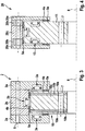
- Die Erfindung wird anhand der beigefügten
Fig. 1 - 5 beispielsweise näher erläutert, wobei jeweils Innenring 1, 10, 11 und Außenring 2, 12, 20 ausschnittsweise im Querschnitt dargestellt sind. - Es zeigen im Einzelnen:
- Fig. 1
- Die Anordnung mit den im Außenring 2 angeordneten Elektromagneten 3a, 3b.
- Fig. 2
- Die Anordnung mit im Innenring 11 angeordneten Elektromagneten 13a, 13b.
- Fig. 3
- Eine Anordnung entsprechend
Fig. 1 mit einem mehrteiligen Innenring 10. - Fig. 4
- Eine Anordnung entsprechend
Fig. 2 mit einem mehrteiligen Außenring 20. - Fig. 5
- Einen Schnitt nach Linie I-I von
Fig. 2 . - Nach
Fig. 1 ist der Außenring 2 als Stator ausgebildet, wobei in den einzelnen Außenringen 2a und 2c die Elektromagnete 3a und im Außenring 2b die Elektromagnete 3b angeordnet sind, die den beiden Axialflächen und der Radialfläche des als Rotor dienenden Innenringes 1 gegenüberliegen. Mit Hilfe dieser Elektromagnete 3a, 3b werden Innenring 1 und Außenring 2 während der Rotation um die gemeinsame Drehachse 8 in einem gleichmäßigem Abstand zueinander gehalten, so dass im Betrieb kein metallischer Kontakt zwischen beiden Lagerringen vorliegt. Zur Kontrolle und Steuerung des Spaltabstandes sind in der Nähe der Elektromagnete 3a, 3b jeweils Abstandssensoren 4a, 4b vorgesehen. Die Fanglager 5a - 5e sind entweder am Außenring 2, 12, 20 oder am Innenring 1, 10, 11 befestigt und besitzen im normalen Betrieb einen geringen Abstand gegenüber der gegenüberliegenden Fläche. Bei Ausfall der Stromversorgung für die Elektromagnete 3a, 3b können diese Fanglager 5a - 5e den jeweils rotierenden Ring tragen. Die Bohrungen 6 und 7 dienen zur Befestigung des jeweiligen Ringes an den nicht dargestellten Anschlusskonstruktionen. - Bei
Fig. 2 ist der Innenring 11 als Stator ausgebildet, an dem die Elektromagnete 13a, 13b angeordnet sind. Der Außenring 12 umschließt mit den einzelnen Ringen 12a, 12b u-förmig das äußere Ende des Innenringes 11, wobei in gleicher Weise die Fanglager 5a, 5c und die Abstandssensoren 4a, 4b im Spalt zwischen den beiden Ringen 11 und 12 angeordnet sind. - In
Fig. 3 ist der Innenring 10 mehrteilig ausgebildet, wobei zwischen den beiden magnetischen Innenringen 10a, 10c ein amagnetischer Innenring 10b angeordnet ist. Am äußeren Umfang kann dieser Innenring 10b als Gleitelement gegenüber dem Fanglager 5e fungieren, wobei als Gleitlagerwerkstoff Kunststoff oder Bronze verwendet wird. - Bei der
Fig. 4 ist der Außenring 20 mehrteilig ausgebildet, wobei zwischen den magnetischen Außenringen 20a und 20c der amagnetische Außenring 20b sich befindet. Die amagnetischen Ringe 10b, 20b dienen zur magnetischen Isolierung zwischen den benachbarten Ringen 10a, 10c bzw. 20a, 20c. Auch der amagnetischen Außenring 20b kann als Gleitelemente gegenüber dem Fanglager 5d genutzt werden. - In
Fig. 5 ist in vergrößerter Darstellung die Anordnung eines Kugellagers mit Kugeln 9 zu sehen, wobei die Kugeln umlaufend in einem Käfig 21 geführt werden. Mit Hilfe der Feder 22 ist ein vorgespannter Käfig 21 vorhanden. Das hat den Vorteil, dass sichergestellt ist, dass das als Wälzlager ausgebildete Fanglager 5c nur dann bewegt wird, wenn das Fanglager 5c tatsächlich belastet wird. Für diesen Fall der Verwendung eines Kugellagers bei der Ausführung nachFig. 2 kann dort auf das Fanglager 5a verzichtet werden. Von Bedeutung ist hierbei auch, dass zwischen dem Außenring 12b und den Kugeln 9 ein Abstand 23 im normalen Betriebszustand des Lagers eingehalten wird. Falls es zu einem Kontakt in diesem Bereich kommt, verhindert das Kugellager eine übermäßige Reibung. -
- 1
- Innenring (als Rotor)
- 2, 2a, 2b, 2c
- Außenring (als Stator)
- 3a, 3b
- Elektromagnet (an 2a, 2b)
- 4a, 4b
- Abstandssensor
- 5a, 5b, 5c, 5d, 5e
- Fanglager
- 6
- Bohrung (für Befestigung von 2 an Anschlusskonstruktion)
- 7
- Bohrung (für Befestigung von 1 an Anschlusskonstruktion)
- 8
- Drehachse (von 1, 2 etc.)
- 9
- Kugel (von 5c)
- 10
- Innenring (mehrteilig, als Rotor)
- 10a, 10c
- Innenring (magnetisch)
- 10b
- Innenring (amagnetisch)
- 11
- Innenring (als Stator)
- 12, 12a, 12b
- Außenring (als Rotor)
- 13a, 13b
- Elektromagnet (an 11)
- 20
- Außenring (mehrteilig, als Rotor)
- 20a, 20c
- Außenring (magnetisch)
- 20b
- Außenring (amagnetisch)
- 21
- Käfig (für 9)
- 22
- Feder
- 23
- Abstand (zwischen 12b und 9)
Claims (9)
- Lager für drehbare Geräte, insbesondere für einen medizinischen Scanner mit einem Innenring (1, 11) und einem Außenring (2, 12), wobei- Innenring (1, 11) und Außenring (2, 12) durch das magnetische Feld von Elektromagneten (3a, 3b) in axialer und/oder radialer Richtung berührungslos geführt sind,- der Abstand zwischen ihnen mit Hilfe von Abstandssensoren (4a, 4b) kontrolliert und gesteuert wird,- der Außenring (2, 12) mehrteilig ausgeführt ist und im zusammengebauten Zustand einen u-förmigen nach innen offenen Querschnitt besitzt,- in den Außenring (2, 12) der Innenring (1, 11) hinein ragt,- in den axial und radial gegenüberliegenden Bereichen von Innenring (1, 11) oder Außenring (2, 12) jeweils Elektromagnete (3a, 3b) und Abstandssensoren (4a, 4b) angeordnet sind,
dadurch gekennzeichnet, dass- neben oder im Bereich der Elektromagnete (3a, 3b) jeweils wenigstens ein Fanglager (5a, 5b, 5c, 5d, 5e) angeordnet ist, das den rotierenden Ring bei Ausfall der Stromversorgung für die Elektromagnete (3a, 3b) trägt und dass- wenigstens eines der Fanglager (5c) als zwischen den radial gegenüberliegenden Bereichen von Innenring (1, 11) und Außenring (2, 12) angeordnetes Radialwälzlager mit Kugeln (9) oder Rollen, die in einem mit mindestens einer Feder (22) vorgespannten Käfig (21) gehalten werden, ausgebildet ist. - Lager für drehbare Geräte, insbesondere für einen medizinischen Scanner mit einem Innenring (10) und einem Außenring (20), wobei- Innenring (10) und Außenring (20) durch das magnetische Feld von Elektromagneten (3a, 3b) in axialer und/oder radialer Richtung berührungslos geführt sind,- der Abstand zwischen ihnen mit Hilfe von Abstandssensoren (4a, 4b) kontrolliert und gesteuert wird,- der Außenring (20) mehrteilig ausgeführt ist und im zusammengebauten Zustand einen u-förmigen nach innen offenen Querschnitt besitzt,- in den Außenring (20) der Innenring (10) hinein ragt,- in den axial und radial gegenüberliegenden Bereichen von Innenring (10) oder Außenring (20) jeweils Elektromagnete (3a, 3b) und Abstandssensoren (4a, 4b) angeordnet sind,
dadurch gekennzeichnet, dass- neben oder im Bereich der Elektromagnete (3a, 3b) jeweils wenigstens ein Fanglager (5a, 5b, 5c, 5d, 5e) angeordnet ist, das den rotierenden Ring bei Ausfall der Stromversorgung für die Elektromagnete (3a, 3b) trägt und dass- wenigstens eines der Fanglager (5d, 5e) als Radialgleitlager ausgebildet ist,- und der Innenring (10) oder Außenring (20), der keinen Elektromagneten (3a, 3b) trägt, aus mehreren magnetischen Ringen (10a, 10c, 20a, 20c) besteht, die durch amagnetische Ringe (10b, 20b) voneinander getrennt sind, und die amagnetischen Ringe (10b, 20b) als Gleitelemente des als Radialgleitlager ausgebildeten Fanglagers (5d, 5e) fungieren. - Lager nach Anspruch 1 oder 2, dadurch gekennzeichnet, dass die Elektromagnete (3a, 3b) in zum gegenüberliegenden Ring offenen Aussparungen entweder im Außenring (2) oder im Innenring (11) angeordnet sind.
- Lager nach Anspruch 1 oder 3, dadurch gekennzeichnet, dass neben oder im Bereich der Elektromagnete (3a, 3b) jeweils ein oder mehrere Abstandssensoren (4a, 4b) angeordnet sind, die optisch, induktiv oder in ähnlicher Weise arbeiten.
- Lager nach Anspruch 1 oder 2 dadurch gekennzeichnet, dass die Abstandssensoren (4a, 4b) und die Elektromagnete (3a, 3b) redundant im Lager angeordnet sind.
- Lager nach Anspruch 1 oder 2, dadurch gekennzeichnet, dass die Abstandssensoren (4a, 4b) und die Elektromagnete (3a, 3b) und die Steuerung mit einer unterbrechungsfreien Stromversorgung verbunden sind.
- Lager nach Anspruch 1 oder 2, dadurch gekennzeichnet, dass der Außenring (2, 12, 20) auf seinem Außendurchmesser mit Eingriffsmöglichkeiten für einen Zahn- oder Keilriemen versehen ist.
- Lager nach Anspruch 1 oder 2, dadurch gekennzeichnet, dass die Abstandssensoren (4a, 4b) und die Elektromagnete (3a, 3b) geschützt eingebaut sind und so geformt sind, dass auch ein Einsatz des Lagers in flüssigen Medien, insbesondere Wasser möglich ist.
- Lager nach Anspruch 2, dadurch gekennzeichnet, dass die amagnetischen Ringe (10b, 20b) aus Kunststoff oder Bronze bestehen.
Applications Claiming Priority (2)
| Application Number | Priority Date | Filing Date | Title |
|---|---|---|---|
| DE102007038489 | 2007-08-14 | ||
| PCT/EP2008/006644 WO2009021721A2 (de) | 2007-08-14 | 2008-08-13 | Verfahren und lager zur lagerung von drehbaren geräten, insbesondere eines medizinischen scanners |
Publications (2)
| Publication Number | Publication Date |
|---|---|
| EP2188541A2 EP2188541A2 (de) | 2010-05-26 |
| EP2188541B1 true EP2188541B1 (de) | 2012-04-18 |
Family
ID=40254412
Family Applications (1)
| Application Number | Title | Priority Date | Filing Date |
|---|---|---|---|
| EP08785520A Not-in-force EP2188541B1 (de) | 2007-08-14 | 2008-08-13 | Verfahren und lager zur lagerung von drehbaren geräten, insbesondere eines medizinischen scanners |
Country Status (5)
| Country | Link |
|---|---|
| US (1) | US8319385B2 (de) |
| EP (1) | EP2188541B1 (de) |
| AT (1) | ATE554298T1 (de) |
| DE (1) | DE102008038978A1 (de) |
| WO (1) | WO2009021721A2 (de) |
Families Citing this family (21)
| Publication number | Priority date | Publication date | Assignee | Title |
|---|---|---|---|---|
| JP5783723B2 (ja) | 2007-12-21 | 2015-09-24 | フォールブルック インテレクチュアル プロパティー カンパニー エルエルシー | 自動変速機及びその方法 |
| DE102008017984A1 (de) * | 2008-04-07 | 2009-10-08 | Rothe Erde Gmbh | Magnetlager sowie Verfahren zur Herstellung eines dafür geeigneten Lagerrings |
| US8317651B2 (en) | 2008-05-07 | 2012-11-27 | Fallbrook Intellectual Property Company Llc | Assemblies and methods for clamping force generation |
| DE102009058354A1 (de) * | 2009-12-15 | 2011-06-16 | Aktiebolaget Skf | Wälzlageranordnung |
| US8270563B2 (en) * | 2010-02-09 | 2012-09-18 | Aktiebolaget Skf | Diagnostic scanning apparatus |
| DE102010022000A1 (de) | 2010-05-29 | 2012-06-14 | Schaeffler Technologies Gmbh & Co. Kg | Fanglager zur Sicherung eines Magnetlagersystems sowie Magnetlagersystem mit dem Fanglager |
| DE102011075768A1 (de) * | 2011-05-12 | 2012-11-15 | Schaeffler Technologies AG & Co. KG | Fanglager |
| CN103244557A (zh) * | 2012-02-08 | 2013-08-14 | 张玉宝 | 一种径轴向磁悬浮轴承 |
| KR101408060B1 (ko) * | 2012-06-19 | 2014-06-18 | 한국기계연구원 | 보조 베어링이 결합된 복합 자기 베어링 |
| US9590468B2 (en) * | 2012-10-08 | 2017-03-07 | Exro Technologies Inc. | Electrical machines such as generators and motors |
| CN104179801A (zh) * | 2013-05-26 | 2014-12-03 | 张玉宝 | 一种径轴向磁悬浮复合单元 |
| US9638249B2 (en) * | 2015-05-12 | 2017-05-02 | Schaeffler Technologies AG & Co. KG | Bearing cage with resilient inserts between pockets |
| DE102015108081A1 (de) * | 2015-05-21 | 2016-11-24 | Thyssenkrupp Ag | Magnetlager und Verfahren zum Betrieb eines Magnetlagers |
| DE102015218626A1 (de) | 2015-09-28 | 2017-03-30 | Aktiebolaget Skf | Signalübertragungsvorrichtung für Lager |
| DE102016116113A1 (de) | 2016-08-30 | 2018-03-01 | Thyssenkrupp Ag | Lager und Verfahren zur Verschleißüberwachung und/oder Lastmessung |
| US20180087516A1 (en) * | 2016-09-27 | 2018-03-29 | General Electric Company | Turbomachine with active magnetic bearings |
| DE102019119727B4 (de) * | 2019-07-22 | 2026-03-19 | Schaeffler Technologies AG & Co. KG | Wellgetriebe |
| DE102019216422A1 (de) * | 2019-10-24 | 2021-04-29 | Aktiebolaget Skf | Wälzlager mit einem Ultraschallabstandssensor |
| CN114198395B (zh) * | 2021-12-09 | 2023-05-23 | 珠海格力电器股份有限公司 | 轴承结构以及具有其的电机 |
| DE102022209410A1 (de) * | 2022-09-09 | 2024-03-14 | Aktiebolaget Skf | Wälzlager mit Abstandssensor |
| DE102022209408A1 (de) * | 2022-09-09 | 2024-03-14 | Aktiebolaget Skf | Wälzlager mit Abstandssensor |
Family Cites Families (16)
| Publication number | Priority date | Publication date | Assignee | Title |
|---|---|---|---|---|
| DE2163199B1 (de) * | 1971-12-20 | 1973-11-22 | Hoesch Werke Ag, 4600 Dortmund | Mittenfreies grosslager |
| DE8122258U1 (de) | 1981-07-29 | 1981-11-05 | Estel Hoesch Werke Ag, 4600 Dortmund | Wälzlager mit Dämpfungsmaterial. |
| JPS58149899A (ja) * | 1982-02-26 | 1983-09-06 | 三菱電機株式会社 | 人口衛星姿勢制御用磁気軸受ホイ−ル |
| US4683111A (en) * | 1986-01-23 | 1987-07-28 | Proto-Power Corporation | Gas circulator for a nuclear reactor and a method for use thereof |
| JPH05122896A (ja) * | 1991-10-30 | 1993-05-18 | Toshiba Corp | スラスト磁気軸受装置 |
| DE4227013A1 (de) * | 1992-08-14 | 1994-02-17 | Budig Peter Klaus Prof Dr Sc T | Aktives magnetisches Axiallager für Rotoren mit Notlauflager |
| JP4024382B2 (ja) * | 1998-05-15 | 2007-12-19 | 株式会社東芝 | 磁気軸受装置 |
| JP2000291655A (ja) * | 1999-04-09 | 2000-10-20 | Nsk Ltd | 磁気軸受の保護用転がり軸受 |
| JP4427938B2 (ja) | 1999-09-30 | 2010-03-10 | 三菱電機株式会社 | スラスト磁気軸受装置 |
| JP2001304258A (ja) * | 2000-04-26 | 2001-10-31 | Ebara Corp | 磁気軸受及び磁気浮上装置 |
| JP3919436B2 (ja) * | 2000-09-13 | 2007-05-23 | 株式会社荏原製作所 | 磁気浮上回転機械 |
| FR2817088B1 (fr) * | 2000-11-17 | 2003-02-21 | Mecanique Magnetique Sa | Machine tournante a butee axiale magnetique integrant une generatrice de courant |
| DE10129160A1 (de) * | 2001-06-16 | 2002-12-19 | W I T Wiemers Innovative Techn | Magnetlager |
| DE10331150B4 (de) | 2003-07-09 | 2007-07-19 | Franke & Heydrich Kg | Wälzlager in Form einer Dreh- und/oder Linearführung |
| DE10338222A1 (de) * | 2003-08-20 | 2005-03-10 | Leybold Vakuum Gmbh | Kombinierter Antrieb mit Lagerung |
| DE102005000754B3 (de) | 2005-01-05 | 2006-10-19 | Rothe Erde Gmbh | Verfahren zur Herstellung von insbesondere geräuschgedämpften Wälzlagern für Schnelllaufanwendungen und zugehöriges Wälzlager |
-
2008
- 2008-08-13 EP EP08785520A patent/EP2188541B1/de not_active Not-in-force
- 2008-08-13 US US12/664,538 patent/US8319385B2/en active Active
- 2008-08-13 AT AT08785520T patent/ATE554298T1/de active
- 2008-08-13 DE DE102008038978A patent/DE102008038978A1/de not_active Ceased
- 2008-08-13 WO PCT/EP2008/006644 patent/WO2009021721A2/de not_active Ceased
Also Published As
| Publication number | Publication date |
|---|---|
| WO2009021721A3 (de) | 2009-07-09 |
| DE102008038978A1 (de) | 2009-04-30 |
| US20100181854A1 (en) | 2010-07-22 |
| EP2188541A2 (de) | 2010-05-26 |
| ATE554298T1 (de) | 2012-05-15 |
| WO2009021721A2 (de) | 2009-02-19 |
| US8319385B2 (en) | 2012-11-27 |
Similar Documents
| Publication | Publication Date | Title |
|---|---|---|
| EP2188541A2 (de) | Verfahren und lager zur lagerung von drehbaren geräten, insbesondere eines medizinischen scanners | |
| EP1972794B1 (de) | Vakuumpumpe | |
| EP2171297B1 (de) | Schrägkugellager in tandemanordnung sowie lageranordnung mit dem schrägkugellager | |
| EP2373457B1 (de) | Lageranordnung mit magnetlagerabschnitt sowie verfahren zur regelung einer oder der lageranordnung | |
| WO2012139830A1 (de) | Lagereinheit für einen turbolader | |
| EP2600005B1 (de) | Vakuumpumpe mit einem käfiglosen Wälzlager | |
| EP2212572A1 (de) | Radial-axial-wälzlager | |
| DE102010054926A1 (de) | Lagereinheit für einen Turbolader | |
| EP0414127A1 (de) | Magnetgelagerte Vakuumpumpe | |
| DE3725027A1 (de) | Drahtwaelzlager mit flachdraht | |
| DE102010054966A1 (de) | Wälzlager | |
| DE102016211569A1 (de) | Lageranordnung für einen Turbolader | |
| EP2286100A1 (de) | Radlageranordnung mit fettverteilerring | |
| DE102009037420A1 (de) | Käfigsegment für einen Kunststoffkäfig eines Wälzlagers und Wälzlager mit einem solchen Käfigsegment | |
| DE102008016798B4 (de) | Wälzlager sowie Lenkgetriebe mit einem derartigen Wälzlager | |
| DE102011087435A1 (de) | Toroidallager | |
| DE102010035785A1 (de) | Wälzlager | |
| DE10260904A1 (de) | Vorrichtung mit einem sich drehenden Element im Umfeld einer Kolbenmaschine, insbesondere eine elektromagnetisch betätigte Reibscheibenkupplung, eine Spannrolle oder ein Schwingungsdämpfer | |
| DE102006042675A1 (de) | Pendelrollenlager | |
| WO2011018490A1 (de) | Käfigsegment für einen kunststoffkäfig eines wälzlagers und wälzlager mit einem solchen käfigsegment | |
| DE102007048669A1 (de) | Lageranordnung zur Aufnahme radialer und axialer Belastungen | |
| DE102012207071A1 (de) | Lagerstelle zur drehbaren Lagerung eines Pumpenrades eines Drehmomentwandlers, Rollenlager der Lagerstelle und Getriebe mit einem Drehmomentwandler und der Lagerstelle | |
| DE102007010716A1 (de) | Vorrichtung zur Lagerung eines Flyerflügels | |
| DE102010033450B4 (de) | Verfahren zum Herstellen von Varianten einer Baureihe von Lageranordnungen, Lageranordnung und Elektromotor | |
| WO2017202404A1 (de) | Wälzlager für anwendungen mit wechselnden hohen und niedrigen lasten |
Legal Events
| Date | Code | Title | Description |
|---|---|---|---|
| PUAI | Public reference made under article 153(3) epc to a published international application that has entered the european phase |
Free format text: ORIGINAL CODE: 0009012 |
|
| 17P | Request for examination filed |
Effective date: 20100315 |
|
| AK | Designated contracting states |
Kind code of ref document: A2 Designated state(s): AT BE BG CH CY CZ DE DK EE ES FI FR GB GR HR HU IE IS IT LI LT LU LV MC MT NL NO PL PT RO SE SI SK TR |
|
| AX | Request for extension of the european patent |
Extension state: AL BA MK RS |
|
| 17Q | First examination report despatched |
Effective date: 20110203 |
|
| GRAC | Information related to communication of intention to grant a patent modified |
Free format text: ORIGINAL CODE: EPIDOSCIGR1 |
|
| GRAP | Despatch of communication of intention to grant a patent |
Free format text: ORIGINAL CODE: EPIDOSNIGR1 |
|
| DAX | Request for extension of the european patent (deleted) | ||
| GRAS | Grant fee paid |
Free format text: ORIGINAL CODE: EPIDOSNIGR3 |
|
| GRAA | (expected) grant |
Free format text: ORIGINAL CODE: 0009210 |
|
| AK | Designated contracting states |
Kind code of ref document: B1 Designated state(s): AT BE BG CH CY CZ DE DK EE ES FI FR GB GR HR HU IE IS IT LI LT LU LV MC MT NL NO PL PT RO SE SI SK TR |
|
| REG | Reference to a national code |
Ref country code: GB Ref legal event code: FG4D Free format text: NOT ENGLISH |
|
| REG | Reference to a national code |
Ref country code: CH Ref legal event code: EP |
|
| REG | Reference to a national code |
Ref country code: IE Ref legal event code: FG4D Free format text: LANGUAGE OF EP DOCUMENT: GERMAN |
|
| REG | Reference to a national code |
Ref country code: AT Ref legal event code: REF Ref document number: 554298 Country of ref document: AT Kind code of ref document: T Effective date: 20120515 |
|
| REG | Reference to a national code |
Ref country code: DE Ref legal event code: R096 Ref document number: 502008007006 Country of ref document: DE Effective date: 20120614 |
|
| REG | Reference to a national code |
Ref country code: NL Ref legal event code: T3 |
|
| REG | Reference to a national code |
Ref country code: SE Ref legal event code: TRGR |
|
| LTIE | Lt: invalidation of european patent or patent extension |
Effective date: 20120418 |
|
| PG25 | Lapsed in a contracting state [announced via postgrant information from national office to epo] |
Ref country code: NO Free format text: LAPSE BECAUSE OF FAILURE TO SUBMIT A TRANSLATION OF THE DESCRIPTION OR TO PAY THE FEE WITHIN THE PRESCRIBED TIME-LIMIT Effective date: 20120718 Ref country code: CY Free format text: LAPSE BECAUSE OF FAILURE TO SUBMIT A TRANSLATION OF THE DESCRIPTION OR TO PAY THE FEE WITHIN THE PRESCRIBED TIME-LIMIT Effective date: 20120418 Ref country code: PL Free format text: LAPSE BECAUSE OF FAILURE TO SUBMIT A TRANSLATION OF THE DESCRIPTION OR TO PAY THE FEE WITHIN THE PRESCRIBED TIME-LIMIT Effective date: 20120418 Ref country code: IS Free format text: LAPSE BECAUSE OF FAILURE TO SUBMIT A TRANSLATION OF THE DESCRIPTION OR TO PAY THE FEE WITHIN THE PRESCRIBED TIME-LIMIT Effective date: 20120818 Ref country code: LT Free format text: LAPSE BECAUSE OF FAILURE TO SUBMIT A TRANSLATION OF THE DESCRIPTION OR TO PAY THE FEE WITHIN THE PRESCRIBED TIME-LIMIT Effective date: 20120418 Ref country code: FI Free format text: LAPSE BECAUSE OF FAILURE TO SUBMIT A TRANSLATION OF THE DESCRIPTION OR TO PAY THE FEE WITHIN THE PRESCRIBED TIME-LIMIT Effective date: 20120418 |
|
| PG25 | Lapsed in a contracting state [announced via postgrant information from national office to epo] |
Ref country code: LV Free format text: LAPSE BECAUSE OF FAILURE TO SUBMIT A TRANSLATION OF THE DESCRIPTION OR TO PAY THE FEE WITHIN THE PRESCRIBED TIME-LIMIT Effective date: 20120418 Ref country code: SI Free format text: LAPSE BECAUSE OF FAILURE TO SUBMIT A TRANSLATION OF THE DESCRIPTION OR TO PAY THE FEE WITHIN THE PRESCRIBED TIME-LIMIT Effective date: 20120418 Ref country code: PT Free format text: LAPSE BECAUSE OF FAILURE TO SUBMIT A TRANSLATION OF THE DESCRIPTION OR TO PAY THE FEE WITHIN THE PRESCRIBED TIME-LIMIT Effective date: 20120820 Ref country code: GR Free format text: LAPSE BECAUSE OF FAILURE TO SUBMIT A TRANSLATION OF THE DESCRIPTION OR TO PAY THE FEE WITHIN THE PRESCRIBED TIME-LIMIT Effective date: 20120719 Ref country code: HR Free format text: LAPSE BECAUSE OF FAILURE TO SUBMIT A TRANSLATION OF THE DESCRIPTION OR TO PAY THE FEE WITHIN THE PRESCRIBED TIME-LIMIT Effective date: 20120418 |
|
| PG25 | Lapsed in a contracting state [announced via postgrant information from national office to epo] |
Ref country code: SK Free format text: LAPSE BECAUSE OF FAILURE TO SUBMIT A TRANSLATION OF THE DESCRIPTION OR TO PAY THE FEE WITHIN THE PRESCRIBED TIME-LIMIT Effective date: 20120418 Ref country code: RO Free format text: LAPSE BECAUSE OF FAILURE TO SUBMIT A TRANSLATION OF THE DESCRIPTION OR TO PAY THE FEE WITHIN THE PRESCRIBED TIME-LIMIT Effective date: 20120418 Ref country code: CZ Free format text: LAPSE BECAUSE OF FAILURE TO SUBMIT A TRANSLATION OF THE DESCRIPTION OR TO PAY THE FEE WITHIN THE PRESCRIBED TIME-LIMIT Effective date: 20120418 Ref country code: DK Free format text: LAPSE BECAUSE OF FAILURE TO SUBMIT A TRANSLATION OF THE DESCRIPTION OR TO PAY THE FEE WITHIN THE PRESCRIBED TIME-LIMIT Effective date: 20120418 Ref country code: EE Free format text: LAPSE BECAUSE OF FAILURE TO SUBMIT A TRANSLATION OF THE DESCRIPTION OR TO PAY THE FEE WITHIN THE PRESCRIBED TIME-LIMIT Effective date: 20120418 |
|
| PLBE | No opposition filed within time limit |
Free format text: ORIGINAL CODE: 0009261 |
|
| STAA | Information on the status of an ep patent application or granted ep patent |
Free format text: STATUS: NO OPPOSITION FILED WITHIN TIME LIMIT |
|
| BERE | Be: lapsed |
Owner name: THYSSENKRUPP TRANSRAPID G.M.B.H. Effective date: 20120831 Owner name: ROTHE ERDE G.M.B.H. Effective date: 20120831 |
|
| PG25 | Lapsed in a contracting state [announced via postgrant information from national office to epo] |
Ref country code: IT Free format text: LAPSE BECAUSE OF FAILURE TO SUBMIT A TRANSLATION OF THE DESCRIPTION OR TO PAY THE FEE WITHIN THE PRESCRIBED TIME-LIMIT Effective date: 20120418 |
|
| 26N | No opposition filed |
Effective date: 20130121 |
|
| REG | Reference to a national code |
Ref country code: CH Ref legal event code: PL |
|
| PG25 | Lapsed in a contracting state [announced via postgrant information from national office to epo] |
Ref country code: MC Free format text: LAPSE BECAUSE OF NON-PAYMENT OF DUE FEES Effective date: 20120831 |
|
| PG25 | Lapsed in a contracting state [announced via postgrant information from national office to epo] |
Ref country code: LI Free format text: LAPSE BECAUSE OF NON-PAYMENT OF DUE FEES Effective date: 20120831 Ref country code: ES Free format text: LAPSE BECAUSE OF FAILURE TO SUBMIT A TRANSLATION OF THE DESCRIPTION OR TO PAY THE FEE WITHIN THE PRESCRIBED TIME-LIMIT Effective date: 20120729 Ref country code: CH Free format text: LAPSE BECAUSE OF NON-PAYMENT OF DUE FEES Effective date: 20120831 |
|
| REG | Reference to a national code |
Ref country code: DE Ref legal event code: R097 Ref document number: 502008007006 Country of ref document: DE Effective date: 20130121 |
|
| REG | Reference to a national code |
Ref country code: IE Ref legal event code: MM4A |
|
| PG25 | Lapsed in a contracting state [announced via postgrant information from national office to epo] |
Ref country code: BE Free format text: LAPSE BECAUSE OF NON-PAYMENT OF DUE FEES Effective date: 20120831 |
|
| PG25 | Lapsed in a contracting state [announced via postgrant information from national office to epo] |
Ref country code: IE Free format text: LAPSE BECAUSE OF NON-PAYMENT OF DUE FEES Effective date: 20120813 Ref country code: BG Free format text: LAPSE BECAUSE OF FAILURE TO SUBMIT A TRANSLATION OF THE DESCRIPTION OR TO PAY THE FEE WITHIN THE PRESCRIBED TIME-LIMIT Effective date: 20120718 |
|
| PG25 | Lapsed in a contracting state [announced via postgrant information from national office to epo] |
Ref country code: MT Free format text: LAPSE BECAUSE OF FAILURE TO SUBMIT A TRANSLATION OF THE DESCRIPTION OR TO PAY THE FEE WITHIN THE PRESCRIBED TIME-LIMIT Effective date: 20120418 |
|
| PG25 | Lapsed in a contracting state [announced via postgrant information from national office to epo] |
Ref country code: TR Free format text: LAPSE BECAUSE OF FAILURE TO SUBMIT A TRANSLATION OF THE DESCRIPTION OR TO PAY THE FEE WITHIN THE PRESCRIBED TIME-LIMIT Effective date: 20120418 |
|
| PG25 | Lapsed in a contracting state [announced via postgrant information from national office to epo] |
Ref country code: LU Free format text: LAPSE BECAUSE OF NON-PAYMENT OF DUE FEES Effective date: 20120813 |
|
| PG25 | Lapsed in a contracting state [announced via postgrant information from national office to epo] |
Ref country code: HU Free format text: LAPSE BECAUSE OF FAILURE TO SUBMIT A TRANSLATION OF THE DESCRIPTION OR TO PAY THE FEE WITHIN THE PRESCRIBED TIME-LIMIT Effective date: 20080813 |
|
| REG | Reference to a national code |
Ref country code: AT Ref legal event code: MM01 Ref document number: 554298 Country of ref document: AT Kind code of ref document: T Effective date: 20130813 |
|
| PG25 | Lapsed in a contracting state [announced via postgrant information from national office to epo] |
Ref country code: AT Free format text: LAPSE BECAUSE OF NON-PAYMENT OF DUE FEES Effective date: 20130813 |
|
| REG | Reference to a national code |
Ref country code: FR Ref legal event code: PLFP Year of fee payment: 9 |
|
| REG | Reference to a national code |
Ref country code: DE Ref legal event code: R081 Ref document number: 502008007006 Country of ref document: DE Owner name: THYSSENKRUPP ROTHE ERDE GERMANY GMBH, DE Free format text: FORMER OWNERS: ROTHE ERDE GMBH, 44137 DORTMUND, DE; THYSSENKRUPP TRANSRAPID GMBH, 34127 KASSEL, DE Ref country code: DE Ref legal event code: R082 Ref document number: 502008007006 Country of ref document: DE Ref country code: DE Ref legal event code: R081 Ref document number: 502008007006 Country of ref document: DE Owner name: THYSSENKRUPP TRANSRAPID GMBH, DE Free format text: FORMER OWNERS: ROTHE ERDE GMBH, 44137 DORTMUND, DE; THYSSENKRUPP TRANSRAPID GMBH, 34127 KASSEL, DE Ref country code: DE Ref legal event code: R081 Ref document number: 502008007006 Country of ref document: DE Owner name: THYSSENKRUPP ROTHE ERDE GMBH, DE Free format text: FORMER OWNERS: ROTHE ERDE GMBH, 44137 DORTMUND, DE; THYSSENKRUPP TRANSRAPID GMBH, 34127 KASSEL, DE |
|
| REG | Reference to a national code |
Ref country code: DE Ref legal event code: R081 Ref document number: 502008007006 Country of ref document: DE Owner name: THYSSENKRUPP ROTHE ERDE GERMANY GMBH, DE Free format text: FORMER OWNERS: THYSSENKRUPP ROTHE ERDE GMBH, 44137 DORTMUND, DE; THYSSENKRUPP TRANSRAPID GMBH, 34127 KASSEL, DE Ref country code: DE Ref legal event code: R081 Ref document number: 502008007006 Country of ref document: DE Owner name: THYSSENKRUPP TRANSRAPID GMBH, DE Free format text: FORMER OWNERS: THYSSENKRUPP ROTHE ERDE GMBH, 44137 DORTMUND, DE; THYSSENKRUPP TRANSRAPID GMBH, 34127 KASSEL, DE Ref country code: DE Ref legal event code: R081 Ref document number: 502008007006 Country of ref document: DE Owner name: THYSSENKRUPP ROTHE ERDE GMBH, DE Free format text: FORMER OWNERS: THYSSENKRUPP ROTHE ERDE GMBH, 44137 DORTMUND, DE; THYSSENKRUPP TRANSRAPID GMBH, 34127 KASSEL, DE |
|
| REG | Reference to a national code |
Ref country code: FR Ref legal event code: PLFP Year of fee payment: 10 |
|
| REG | Reference to a national code |
Ref country code: DE Ref legal event code: R083 Ref document number: 502008007006 Country of ref document: DE |
|
| REG | Reference to a national code |
Ref country code: FR Ref legal event code: PLFP Year of fee payment: 11 |
|
| PGFP | Annual fee paid to national office [announced via postgrant information from national office to epo] |
Ref country code: NL Payment date: 20180821 Year of fee payment: 11 Ref country code: FR Payment date: 20180827 Year of fee payment: 11 |
|
| PGFP | Annual fee paid to national office [announced via postgrant information from national office to epo] |
Ref country code: GB Payment date: 20180822 Year of fee payment: 11 Ref country code: SE Payment date: 20180823 Year of fee payment: 11 |
|
| REG | Reference to a national code |
Ref country code: DE Ref legal event code: R081 Ref document number: 502008007006 Country of ref document: DE Owner name: THYSSENKRUPP ROTHE ERDE GERMANY GMBH, DE Free format text: FORMER OWNERS: THYSSENKRUPP ROTHE ERDE GMBH, 44137 DORTMUND, DE; THYSSENKRUPP TRANSRAPID GMBH, 34127 KASSEL, DE Ref country code: DE Ref legal event code: R081 Ref document number: 502008007006 Country of ref document: DE Owner name: THYSSENKRUPP TRANSRAPID GMBH, DE Free format text: FORMER OWNERS: THYSSENKRUPP ROTHE ERDE GMBH, 44137 DORTMUND, DE; THYSSENKRUPP TRANSRAPID GMBH, 34127 KASSEL, DE |
|
| REG | Reference to a national code |
Ref country code: NL Ref legal event code: MM Effective date: 20190901 |
|
| REG | Reference to a national code |
Ref country code: SE Ref legal event code: EUG |
|
| GBPC | Gb: european patent ceased through non-payment of renewal fee |
Effective date: 20190813 |
|
| PG25 | Lapsed in a contracting state [announced via postgrant information from national office to epo] |
Ref country code: SE Free format text: LAPSE BECAUSE OF NON-PAYMENT OF DUE FEES Effective date: 20190814 |
|
| PG25 | Lapsed in a contracting state [announced via postgrant information from national office to epo] |
Ref country code: FR Free format text: LAPSE BECAUSE OF NON-PAYMENT OF DUE FEES Effective date: 20190831 Ref country code: NL Free format text: LAPSE BECAUSE OF NON-PAYMENT OF DUE FEES Effective date: 20190901 |
|
| PG25 | Lapsed in a contracting state [announced via postgrant information from national office to epo] |
Ref country code: GB Free format text: LAPSE BECAUSE OF NON-PAYMENT OF DUE FEES Effective date: 20190813 |
|
| PGFP | Annual fee paid to national office [announced via postgrant information from national office to epo] |
Ref country code: DE Payment date: 20200819 Year of fee payment: 13 |
|
| REG | Reference to a national code |
Ref country code: DE Ref legal event code: R119 Ref document number: 502008007006 Country of ref document: DE |
|
| PG25 | Lapsed in a contracting state [announced via postgrant information from national office to epo] |
Ref country code: DE Free format text: LAPSE BECAUSE OF NON-PAYMENT OF DUE FEES Effective date: 20220301 |