EP2188411B1 - Sputtersystem - Google Patents
Sputtersystem Download PDFInfo
- Publication number
- EP2188411B1 EP2188411B1 EP08807390A EP08807390A EP2188411B1 EP 2188411 B1 EP2188411 B1 EP 2188411B1 EP 08807390 A EP08807390 A EP 08807390A EP 08807390 A EP08807390 A EP 08807390A EP 2188411 B1 EP2188411 B1 EP 2188411B1
- Authority
- EP
- European Patent Office
- Prior art keywords
- plasma
- sputtering
- substrate
- magnets
- magnetic
- Prior art date
- Legal status (The legal status is an assumption and is not a legal conclusion. Google has not performed a legal analysis and makes no representation as to the accuracy of the status listed.)
- Not-in-force
Links
Images


Classifications
-
- H—ELECTRICITY
- H01—ELECTRIC ELEMENTS
- H01J—ELECTRIC DISCHARGE TUBES OR DISCHARGE LAMPS
- H01J37/00—Discharge tubes with provision for introducing objects or material to be exposed to the discharge, e.g. for the purpose of examination or processing thereof
- H01J37/32—Gas-filled discharge tubes
- H01J37/34—Gas-filled discharge tubes operating with cathodic sputtering
- H01J37/3402—Gas-filled discharge tubes operating with cathodic sputtering using supplementary magnetic fields
- H01J37/3405—Magnetron sputtering
- H01J37/3408—Planar magnetron sputtering
-
- H—ELECTRICITY
- H01—ELECTRIC ELEMENTS
- H01J—ELECTRIC DISCHARGE TUBES OR DISCHARGE LAMPS
- H01J37/00—Discharge tubes with provision for introducing objects or material to be exposed to the discharge, e.g. for the purpose of examination or processing thereof
- H01J37/32—Gas-filled discharge tubes
- H01J37/32431—Constructional details of the reactor
- H01J37/3266—Magnetic control means
- H01J37/32678—Electron cyclotron resonance
Definitions
- the invention relates to a device for sputtering at least one selected material onto a substrate and bringing about a reaction of this material, comprising a vacuum chamber, in which a substrate holder is arranged, at least one magnetron sputtering mechanism, which is arranged in a workstation close to the substrate holder and which has a target of the selected material which is suitable for producing a first plasma for sputtering at least one material onto the substrate, as well as a secondary plasma mechanism for producing a secondary plasma, which is arranged in the workstation close to the magnetron sputtering mechanism and close to the substrate holder, the sputtering mechanism and the secondary plasma mechanism forming a sputtering zone and an activation zone.
- the invention also relates to a method for coating a substrate, in which firstly material is deposited on a substrate by means of a sputtering process and the deposited material then reacts in plasma, which contains the necessary reactive species, to form a compound.
- reactive magnetron sputtering is known for applying thin films of metal compounds.
- a reactive sputtering is carried out in this connection such that the substrate is fastened over the metallic target and a compounding of the applied metal film takes place at the same time and at the same location as the depositing of the metal atoms.
- careful balancing of the conditions is necessary, so the film is completely composed or compounded on the substrate, but the sputtering target surface is not "poisoned" by excessive reaction, as a state such as this leads to lower sputtering rates and often to arc formation on the target surface.
- the substrate on which the metal compound is to be deposited, alternatingly over the sputtering target and through a reactive atmosphere.
- the depositing of the metal atoms is in each case partially separated, with respect to time and space, from the compounding of the film.
- the depositing of an oxide layer can be improved in that oxygen in the compounding zone is activated by a plasma, as excited oxygen species react more easily with the metal layer.
- a magnetron sputtering device in which a sputtering mechanism and a secondary plasma mechanism are arranged, which in each case form sputtering and activation zones, which are atmospherically and physically adjacent, and are suitable for improving the plasma of the sputtering mechanism to bring about a reaction of the ions of the reactive gas with the sputtering material with a comparatively low ambient part pressure of the reactive gas.
- a substrate holder is provided, which guides the substrates past the associated selected workstations.
- a device is provided by the invention, in which the reaction rate in the activation zone is increased, so the process times can be reduced.
- all the magnets arranged to produce the magnetic field are arranged outside the vacuum chamber. This facilitates the mechanical arrangement. Furthermore, the outlay for cooling the magnetic components is reduced.
- all the magnets arranged to produce the magnetic field are arranged inside the vacuum chamber. This reduces the installation size of the device.
- At least one electromagnet is preferably connected to an alternating voltage source to produce a magnetic alternating field.
- at least one of the electromagnets producing a magnetic alternating field is arranged in front of the substrate holder. As a result, the ion flow inside the plasma is further concentrated on the substrate.
- At least one electromagnet is connected to a direct voltage source to produce a constant magnetic field.
- At least one electromagnet is preferably operated in such a way that a superimposed constant and alternating field is produced, so that a change in the magnetic field strength is implemented without a polarity reversal of the magnetic field. As a result, an effective compression of the plasma and a release of the ions necessary for the reaction on the substrate is brought about.
- the secondary plasma mechanism is a microwave generator. Generators of this type have been successful in producing the required plasma.
- the arranged magnets advantageously generate magnetic fields with a maximum magnetic flux density, which is above the necessary magnetic flux density depending on the microwave frequency that is necessary to produce electron cyclotron resonance (ECR) in microwave plasma.
- ECR electron cyclotron resonance
- a magnetic flux density of 875 Gauss is produced from this for a typical microwave frequency of 2.45 GHz, so that ECR conditions are present.
- a potential is applied at the substrate holder, which is different from the potential of the vacuum chamber.
- a further acceleration of the plasma ions is brought about in the direction of the substrate.
- the invention is further based on an object of providing a method for coating a substrate, in which the reaction rate of the reaction to be brought about of the metal deposited on the substrate, for example an oxidation, is increased.
- this object is achieved in that the density and the degree of ionization of the plasma is increased with the aid of magnetic fields, which are produced by at least two electromagnets and/or radially magnetized toric magnets as well as at least one magnetic multipole, which is formed from a plurality of permanent magnets.
- a method for coating a substrate is provided by the invention, in which the reaction rate of the reaction to be brought about of the deposited metal on the substrate is increased.
- the sputtering device selected as an embodiment is a development of the sputtering system as described in EP 0 516 436 B1 , reference being made here to the disclosure of this document.
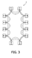
- a sputtering system 10 has a housing 11, the periphery of which forms a vacuum chamber.
- the housing 11 may itself be connected to a vacuum system, not shown.
- a magnetron sputtering device 15 is arranged on the periphery of the vacuum housing of the housing 11, which is also designated hereinafter as the chamber 11, closely adjacent to the plasma production device 16.
- the plasma production device 16 is a microwave generator.
- an inert sputtering gas such as, for example, argon
- a reaction gas such as, for example, oxygen
- the substrates are rotated into the region 19 of the larger plasma 111, a metal film sputtered from the target 15 is deposited.
- the reaction of this film with the reaction gas begins directly when the film is deposited in the region 19 below the target 15. If the substrate 5 is guided into the region 18 of the plasma under the microwave generator 16, this reaction is continued and the conversion of the film into a dielectric with the desired stoichiometry is brought to an end.
- this sequence can be repeated by rotating the drum 12.
- multi-layer films of various materials can be applied to the substrates 5.
- the oxidation rate - arranged in the activation zone in the region 18 is a magnetic field arrangement, consisting of two electromagnets 1, 3 and a magnetic multipole 2, which is constructed from a plurality of permanent magnets.
- the magnetic fields are used to include the electrons.
- the microwave generator 16 operates at 2.45 gigahertz and the magnetic fields initiated by the magnetic field arrangement have a maximum magnetic flux density of more than 875 Gauss, so a resonance state (ECR state) is brought about.
- ECR state resonance state
- an electromagnet is arranged inside the drum 12.
- the multipole magnet 2 and a second electromagnet 3 are arranged with respect to the electromagnet 1 outside the vacuum chamber on the housing 11.
- the substrates 5 fastened to the drum 12 are moved on the rotating drum 12 by the magnetic field configuration.
- a magnetic double mirror is constructed, which is used for the axial inclusion of the electrons.
- radially magnetized toric magnets can also be used here. Owing to the curvature of the magnetic mirror field, a drift of the electrons radially outwardly takes place. This drift movement leads to plasma instabilities.
- a radial magnetic inclusion of the electrons is implemented with the aid of the multipole magnet 2, which is arranged between the two electromagnets 1, 3.
- ECR conditions leads to an increase in the absorption of microwave energy in the plasma by means of the resonant excitation of the electrons when passing through the ECR surfaces.
- increased ionization processes occur and therefore an increase in the charge carrier density (plasma excitation).
- the ions are included by the plasma potential distribution forming (electrostatic inclusion).
- the cause of the plasma potential distribution is large gradients in the electron density and electron temperature. These gradients are produced from the ECR conditions occurring locally to a limited extent (location of the maximum electron excitation by the microwaves).
- this microwave window 4 should be positioned in such a way that no ECR conditions are present on the vacuum side directly in front of the microwave window 4. An excessive thermal stressing of the microwave window 4 is thus prevented.
- the ECR surface of the electromagnet 3 remote from the drum should preferably be arranged on the atmosphere side. Furthermore, the microwave window 4 is protected by keeping away the plasma via the magnetic plasma inclusion.
Landscapes
- Physics & Mathematics (AREA)
- Engineering & Computer Science (AREA)
- Plasma & Fusion (AREA)
- Chemical & Material Sciences (AREA)
- Analytical Chemistry (AREA)
- Physical Vapour Deposition (AREA)
Claims (15)
- Einrichtung (10), um mindestens ein ausgewähltes Material auf ein Substrat (5) aufzusputtern und eine Reaktion dieses Materials zu bewirken, wobei die Einrichtung eine Vakuumkammer (11), in der ein Substrathalter (12) angeordnet ist, mindestens einen Magnetron-Sputtermechanismus (15), der in einer Arbeitsstation in der Nähe des Substrathalters (12) angeordnet ist und der ein Targetmaterial des ausgewählten Materials aufweist, das sich zur Erzeugung eines ersten Plasmas eignet, um mindestens ein Material auf das Substrat (5) aufzusputtern, sowie einen sekundären Plasmamechanismus (16) zur Erzeugung eines sekundären Plasmas, der in der Arbeitsstation in der Nähe des Magnetron-Sputtermechanismus (15) und in der Nähe des Substrathalters (12) angeordnet ist, umfasst, wobei der Magnetron-Sputtermechanismus (15) und der sekundäre Plasmamechanismus (16) eine Sputterzone und eine Aktivierungszone bilden, dadurch gekennzeichnet, dass mindestens zwei Elektromagnete (1, 3) und/oder radial magnetisierte Ringmagnete sowie mindestens ein magnetischer Multipol (2), der aus mehreren Permanentmagneten gebildet wird, so angeordnet sind, dass sie Magnetfelder erzeugen, um das sekundäre Plasma einzuschließen.
- Einrichtung nach Anspruch 1, dadurch gekennzeichnet, dass es sich bei dem Substrathalter (12) um eine Trommel handelt, und dass mindestens ein Elektromagnet (1) und/oder ein radial magnetisierter Ringmagnet innerhalb der Trommel (12) angeordnet sind/ist.
- Einrichtung nach Anspruch 1, dadurch gekennzeichnet, dass sämtliche zur Erzeugung der Magnetfelder angeordnete Magnete (1, 2, 3) außerhalb der Vakuumkammer (11) angeordnet sind.
- Einrichtung nach Anspruch 1 oder 2, dadurch gekennzeichnet, dass sämtliche zur Erzeugung der Magnetfelder angeordnete Magnete (1, 2, 3) innerhalb der Vakuumkammer angeordnet sind.
- Einrichtung nach einem der vorangegangenen Ansprüche, dadurch gekennzeichnet, dass mindestens ein Elektromagnet zur Erzeugung eines magnetischen Wechselfeldes an eine Wechselspannungsquelle angeschlossen ist.
- Einrichtung nach einem der vorangegangenen Ansprüche, dadurch gekennzeichnet, dass mindestens ein Elektromagnet zur Erzeugung eines konstanten Magnetfeldes an eine Gleichspannungsquelle angeschlossen ist.
- Einrichtung nach einem der vorangegangenen Ansprüche, dadurch gekennzeichnet, dass mindestens ein Elektromagnet so betrieben wird, dass ein überlagertes konstantes und Wechselfeld erzeugt wird.
- Einrichtung nach einem der vorangegangenen Ansprüche, dadurch gekennzeichnet, dass es sich bei dem sekundären Plasmamechanismus (16) um einen Mikrowellengenerator handelt.
- Einrichtung nach Anspruch 8, dadurch gekennzeichnet, dass der Mikrowellengenerator (16) so eingerichtet ist, dass er eine gepulste Mikrowelle erzeugt.
- Einrichtung nach den Ansprüchen 8 und 9, dadurch gekennzeichnet, dass die maximale Magnetflussdichte der durch die angeordneten Magneten (1, 2, 3) erzeugten Magnetfelder zumindest der erforderlichen Magnetflussdichte entspricht, die auf die zur Erzeugung von ECR (Electron Cyclotron Resonance) verwendete Mikrowellenfrequenz abgestimmt ist.
- Einrichtung nach einem der vorangegangenen Ansprüche, dadurch gekennzeichnet, dass an den Substrathalter (12) ein Potential angelegt wird, das sich von dem Potential der Vakuumkammer (11) unterscheidet.
- Einrichtung nach einem der vorangegangenen Ansprüche, dadurch gekennzeichnet, dass das sekundäre Plasma eine Reaktion bewirkt, um das ausgewählte Material in ein Oxid, Nitrid, Carbid, Hydrid, Sulfid, Oxynitrid oder Mischungen daraus umzuwandeln.
- Einrichtung nach einem der vorangegangenen Ansprüche, dadurch gekennzeichnet, dass das sekundäre Plasma ein sauerstoffreiches Plasma ist, und dass die hervorgerufene Reaktion eine Oxidation ist.
- Verfahren zur Beschichtung eines Substrats, wobei zuerst Material auf ein Substrat mittels eines Sputterprozesses aufgebracht wird und das aufgebrachte Material sodann in einem Plasma reagiert, das die erforderliche reaktive Spezies enthält, um eine Verbindung herzustellen, dadurch gekennzeichnet, dass die Plasmadichte und der Grad der Ionisierung des Plasmas mit Hilfe von Magnetfeldern erhöht werden, die durch die Einrichtung nach einem der vorangegangenen Ansprüche erzeugt werden.
- Verfahren nach Anspruch 14, dadurch gekennzeichnet, dass die maximale Magnetflussdichte der durch die angeordneten Magneten (1, 2, 3) erzeugten Magnetfelder zumindest der erforderlichen Magnetflussdichte entspricht, die auf die zur Erzeugung von ECR (Electron Cyclotron Resonance) verwendete Mikrowellenfrequenz abgestimmt ist.
Priority Applications (1)
| Application Number | Priority Date | Filing Date | Title |
|---|---|---|---|
| EP08807390A EP2188411B1 (de) | 2007-08-30 | 2008-08-21 | Sputtersystem |
Applications Claiming Priority (3)
| Application Number | Priority Date | Filing Date | Title |
|---|---|---|---|
| EP07115308 | 2007-08-30 | ||
| EP08807390A EP2188411B1 (de) | 2007-08-30 | 2008-08-21 | Sputtersystem |
| PCT/IB2008/053354 WO2009027905A2 (en) | 2007-08-30 | 2008-08-21 | Sputtering system |
Publications (2)
| Publication Number | Publication Date |
|---|---|
| EP2188411A2 EP2188411A2 (de) | 2010-05-26 |
| EP2188411B1 true EP2188411B1 (de) | 2011-10-26 |
Family
ID=40280797
Family Applications (1)
| Application Number | Title | Priority Date | Filing Date |
|---|---|---|---|
| EP08807390A Not-in-force EP2188411B1 (de) | 2007-08-30 | 2008-08-21 | Sputtersystem |
Country Status (6)
| Country | Link |
|---|---|
| US (1) | US20110233049A1 (de) |
| EP (1) | EP2188411B1 (de) |
| JP (1) | JP2010538157A (de) |
| CN (1) | CN101796213B (de) |
| AT (1) | ATE530679T1 (de) |
| WO (1) | WO2009027905A2 (de) |
Families Citing this family (3)
| Publication number | Priority date | Publication date | Assignee | Title |
|---|---|---|---|---|
| CN104505327B (zh) * | 2014-12-19 | 2018-03-27 | 中国科学院嘉兴微电子仪器与设备工程中心 | 一种应用于等离子体设备的腔室结构及等离子体设备 |
| US10153133B2 (en) * | 2015-03-23 | 2018-12-11 | Applied Materials, Inc. | Plasma reactor having digital control over rotation frequency of a microwave field with direct up-conversion |
| CN105624624B (zh) * | 2016-02-25 | 2018-02-13 | 深圳大学 | 一种ecr等离子体溅射装置及其溅射方法 |
Family Cites Families (21)
| Publication number | Priority date | Publication date | Assignee | Title |
|---|---|---|---|---|
| US4876983A (en) * | 1987-01-19 | 1989-10-31 | Hitachi, Ltd. | Plasma operation apparatus |
| DE3727901A1 (de) * | 1987-08-21 | 1989-03-02 | Leybold Ag | Zerstaeubungskathode nach dem magnetronprinzip |
| DE3803355A1 (de) * | 1988-02-05 | 1989-08-17 | Leybold Ag | Teilchenquelle fuer eine reaktive ionenstrahlaetz- oder plasmadepositionsanlage |
| DE3920835C2 (de) * | 1989-06-24 | 1997-12-18 | Leybold Ag | Einrichtung zum Beschichten von Substraten |
| DE69216685T2 (de) * | 1991-05-31 | 1997-05-28 | Deposition Sciences Inc | Sputteranlage |
| US5198725A (en) * | 1991-07-12 | 1993-03-30 | Lam Research Corporation | Method of producing flat ecr layer in microwave plasma device and apparatus therefor |
| US5306985A (en) * | 1992-07-17 | 1994-04-26 | Sematech, Inc. | ECR apparatus with magnetic coil for plasma refractive index control |
| JPH08511830A (ja) * | 1993-06-17 | 1996-12-10 | デポジション・サイエンシス,インコーポレイテッド | スパッタリング装置 |
| US6402902B1 (en) * | 1995-02-13 | 2002-06-11 | Deposition Sciences, Inc. | Apparatus and method for a reliable return current path for sputtering processes |
| DK0908535T3 (da) * | 1997-10-08 | 2003-11-10 | Cockerill Rech & Dev | Fremgangsmåde til at dekapere et substrat og anlæg til at udføre fremgangsmåden |
| JP3735461B2 (ja) * | 1998-03-27 | 2006-01-18 | 株式会社シンクロン | 複合金属の化合物薄膜形成方法及びその薄膜形成装置 |
| DE19824364A1 (de) * | 1998-05-30 | 1999-12-02 | Bosch Gmbh Robert | Verfahren zum Aufbringen eines Verschleißschutz-Schichtsystems mit optischen Eigenschaften auf Oberflächen |
| JP2001176698A (ja) * | 1999-12-21 | 2001-06-29 | Hitachi Ltd | プラズマ処理装置 |
| JP3774353B2 (ja) * | 2000-02-25 | 2006-05-10 | 株式会社シンクロン | 金属化合物薄膜の形成方法およびその形成装置 |
| SE525231C2 (sv) * | 2001-06-14 | 2005-01-11 | Chemfilt R & D Ab | Förfarande och anordning för att alstra plasma |
| US6635124B1 (en) * | 2002-08-29 | 2003-10-21 | General Electric Company | Method of depositing a thermal barrier coating |
| AU2003299015A1 (en) * | 2002-09-19 | 2004-04-08 | Applied Process Technologies, Inc. | Beam plasma source |
| WO2005035822A1 (en) * | 2003-10-07 | 2005-04-21 | Deposition Sciences, Inc. | Apparatus and process for high rate deposition of rutile titanium dioxide |
| US7095179B2 (en) * | 2004-02-22 | 2006-08-22 | Zond, Inc. | Methods and apparatus for generating strongly-ionized plasmas with ionizational instabilities |
| WO2006025336A1 (ja) * | 2004-08-30 | 2006-03-09 | Ulvac, Inc. | 成膜装置 |
| US8192597B2 (en) * | 2006-03-28 | 2012-06-05 | Nv Bekaert Sa | Coating apparatus |
-
2008
- 2008-08-21 AT AT08807390T patent/ATE530679T1/de not_active IP Right Cessation
- 2008-08-21 EP EP08807390A patent/EP2188411B1/de not_active Not-in-force
- 2008-08-21 JP JP2010522488A patent/JP2010538157A/ja active Pending
- 2008-08-21 WO PCT/IB2008/053354 patent/WO2009027905A2/en active Application Filing
- 2008-08-21 CN CN2008801050481A patent/CN101796213B/zh not_active Expired - Fee Related
- 2008-08-21 US US12/674,182 patent/US20110233049A1/en not_active Abandoned
Also Published As
| Publication number | Publication date |
|---|---|
| CN101796213A (zh) | 2010-08-04 |
| JP2010538157A (ja) | 2010-12-09 |
| CN101796213B (zh) | 2012-07-11 |
| WO2009027905A3 (en) | 2009-04-30 |
| ATE530679T1 (de) | 2011-11-15 |
| EP2188411A2 (de) | 2010-05-26 |
| WO2009027905A2 (en) | 2009-03-05 |
| US20110233049A1 (en) | 2011-09-29 |
Similar Documents
| Publication | Publication Date | Title |
|---|---|---|
| CN1800441B (zh) | 等离子体增强薄膜沉积方法及装置 | |
| JP3775689B2 (ja) | 材料をイオン化スパッタリングする方法と装置 | |
| EP0115119B1 (de) | Gestaltete Feld-Magnetronelektrode | |
| EP0379828B1 (de) | Radiofrequenzinduktion/Mehrpolplasma-Bearbeitungsvorrichtung | |
| US6117279A (en) | Method and apparatus for increasing the metal ion fraction in ionized physical vapor deposition | |
| US5178743A (en) | Cylindrical magnetron sputtering system | |
| EP0103461A2 (de) | Vorrichtung und Verfahren zum Auftragen mittels Plasma | |
| EP2695969B1 (de) | Beschichtungsvorrichtung und Verfahren zur Beschichtung eines Dünnfilms | |
| EP1978127A1 (de) | Spritzvorrichtung und folienformungsverfahren | |
| KR20070014992A (ko) | 스퍼터링 장치 및 스퍼터링 방법 | |
| EP2188411B1 (de) | Sputtersystem | |
| US5397448A (en) | Device for generating a plasma by means of cathode sputtering and microwave-irradiation | |
| EP0084971B2 (de) | Verfahren zur reaktiven vorgespannten Zerstäubung | |
| JP2008053116A (ja) | イオンガン、及び成膜装置 | |
| EP2509100B1 (de) | Integrierte Anode und aktivierte reaktive Gasquelle zur Verwendung in einer Magnetron-Sputtervorrichtung | |
| Peng et al. | Plasma-based processes and thin film equipment for nano-scale device fabrication | |
| WO2000003055A1 (en) | Shield for ionized physical vapor deposition apparatus | |
| EP3719833B1 (de) | Oberflächenverarbeitungsvorrichtung | |
| WO1998005057A1 (en) | Magnetron | |
| JPS62224686A (ja) | イオン源 | |
| KR102560323B1 (ko) | 플라스마 처리 장치 및 플라스마 처리 방법 | |
| EP0790328A1 (de) | Dünnschichtabscheidung | |
| JP2009030133A (ja) | 薄膜形成装置並びに薄膜形成方法 | |
| JPS5992995A (ja) | 高融点金属シリサイド膜の形成方法 | |
| JP2009249710A (ja) | 薄膜形成装置 |
Legal Events
| Date | Code | Title | Description |
|---|---|---|---|
| PUAI | Public reference made under article 153(3) epc to a published international application that has entered the european phase |
Free format text: ORIGINAL CODE: 0009012 |
|
| 17P | Request for examination filed |
Effective date: 20100330 |
|
| AK | Designated contracting states |
Kind code of ref document: A2 Designated state(s): AT BE BG CH CY CZ DE DK EE ES FI FR GB GR HR HU IE IS IT LI LT LU LV MC MT NL NO PL PT RO SE SI SK TR |
|
| AX | Request for extension of the european patent |
Extension state: AL BA MK RS |
|
| GRAP | Despatch of communication of intention to grant a patent |
Free format text: ORIGINAL CODE: EPIDOSNIGR1 |
|
| GRAS | Grant fee paid |
Free format text: ORIGINAL CODE: EPIDOSNIGR3 |
|
| GRAA | (expected) grant |
Free format text: ORIGINAL CODE: 0009210 |
|
| AK | Designated contracting states |
Kind code of ref document: B1 Designated state(s): AT BE BG CH CY CZ DE DK EE ES FI FR GB GR HR HU IE IS IT LI LT LU LV MC MT NL NO PL PT RO SE SI SK TR |
|
| DAX | Request for extension of the european patent (deleted) | ||
| REG | Reference to a national code |
Ref country code: GB Ref legal event code: FG4D |
|
| REG | Reference to a national code |
Ref country code: CH Ref legal event code: EP |
|
| REG | Reference to a national code |
Ref country code: IE Ref legal event code: FG4D |
|
| REG | Reference to a national code |
Ref country code: DE Ref legal event code: R096 Ref document number: 602008010932 Country of ref document: DE Effective date: 20111229 |
|
| REG | Reference to a national code |
Ref country code: DE Ref legal event code: R084 Ref document number: 602008010932 Country of ref document: DE Effective date: 20111029 |
|
| REG | Reference to a national code |
Ref country code: GB Ref legal event code: 746 Effective date: 20120109 |
|
| REG | Reference to a national code |
Ref country code: NL Ref legal event code: VDEP Effective date: 20111026 |
|
| LTIE | Lt: invalidation of european patent or patent extension |
Effective date: 20111026 |
|
| REG | Reference to a national code |
Ref country code: AT Ref legal event code: MK05 Ref document number: 530679 Country of ref document: AT Kind code of ref document: T Effective date: 20111026 |
|
| PG25 | Lapsed in a contracting state [announced via postgrant information from national office to epo] |
Ref country code: IS Free format text: LAPSE BECAUSE OF FAILURE TO SUBMIT A TRANSLATION OF THE DESCRIPTION OR TO PAY THE FEE WITHIN THE PRESCRIBED TIME-LIMIT Effective date: 20120226 Ref country code: BE Free format text: LAPSE BECAUSE OF FAILURE TO SUBMIT A TRANSLATION OF THE DESCRIPTION OR TO PAY THE FEE WITHIN THE PRESCRIBED TIME-LIMIT Effective date: 20111026 Ref country code: NO Free format text: LAPSE BECAUSE OF FAILURE TO SUBMIT A TRANSLATION OF THE DESCRIPTION OR TO PAY THE FEE WITHIN THE PRESCRIBED TIME-LIMIT Effective date: 20120126 Ref country code: LT Free format text: LAPSE BECAUSE OF FAILURE TO SUBMIT A TRANSLATION OF THE DESCRIPTION OR TO PAY THE FEE WITHIN THE PRESCRIBED TIME-LIMIT Effective date: 20111026 |
|
| PG25 | Lapsed in a contracting state [announced via postgrant information from national office to epo] |
Ref country code: GR Free format text: LAPSE BECAUSE OF FAILURE TO SUBMIT A TRANSLATION OF THE DESCRIPTION OR TO PAY THE FEE WITHIN THE PRESCRIBED TIME-LIMIT Effective date: 20120127 Ref country code: SI Free format text: LAPSE BECAUSE OF FAILURE TO SUBMIT A TRANSLATION OF THE DESCRIPTION OR TO PAY THE FEE WITHIN THE PRESCRIBED TIME-LIMIT Effective date: 20111026 Ref country code: NL Free format text: LAPSE BECAUSE OF FAILURE TO SUBMIT A TRANSLATION OF THE DESCRIPTION OR TO PAY THE FEE WITHIN THE PRESCRIBED TIME-LIMIT Effective date: 20111026 Ref country code: SE Free format text: LAPSE BECAUSE OF FAILURE TO SUBMIT A TRANSLATION OF THE DESCRIPTION OR TO PAY THE FEE WITHIN THE PRESCRIBED TIME-LIMIT Effective date: 20111026 Ref country code: HR Free format text: LAPSE BECAUSE OF FAILURE TO SUBMIT A TRANSLATION OF THE DESCRIPTION OR TO PAY THE FEE WITHIN THE PRESCRIBED TIME-LIMIT Effective date: 20111026 Ref country code: PT Free format text: LAPSE BECAUSE OF FAILURE TO SUBMIT A TRANSLATION OF THE DESCRIPTION OR TO PAY THE FEE WITHIN THE PRESCRIBED TIME-LIMIT Effective date: 20120227 Ref country code: PL Free format text: LAPSE BECAUSE OF FAILURE TO SUBMIT A TRANSLATION OF THE DESCRIPTION OR TO PAY THE FEE WITHIN THE PRESCRIBED TIME-LIMIT Effective date: 20111026 Ref country code: LV Free format text: LAPSE BECAUSE OF FAILURE TO SUBMIT A TRANSLATION OF THE DESCRIPTION OR TO PAY THE FEE WITHIN THE PRESCRIBED TIME-LIMIT Effective date: 20111026 |
|
| PG25 | Lapsed in a contracting state [announced via postgrant information from national office to epo] |
Ref country code: CY Free format text: LAPSE BECAUSE OF FAILURE TO SUBMIT A TRANSLATION OF THE DESCRIPTION OR TO PAY THE FEE WITHIN THE PRESCRIBED TIME-LIMIT Effective date: 20111026 |
|
| PG25 | Lapsed in a contracting state [announced via postgrant information from national office to epo] |
Ref country code: BG Free format text: LAPSE BECAUSE OF FAILURE TO SUBMIT A TRANSLATION OF THE DESCRIPTION OR TO PAY THE FEE WITHIN THE PRESCRIBED TIME-LIMIT Effective date: 20120126 Ref country code: SK Free format text: LAPSE BECAUSE OF FAILURE TO SUBMIT A TRANSLATION OF THE DESCRIPTION OR TO PAY THE FEE WITHIN THE PRESCRIBED TIME-LIMIT Effective date: 20111026 Ref country code: CZ Free format text: LAPSE BECAUSE OF FAILURE TO SUBMIT A TRANSLATION OF THE DESCRIPTION OR TO PAY THE FEE WITHIN THE PRESCRIBED TIME-LIMIT Effective date: 20111026 Ref country code: EE Free format text: LAPSE BECAUSE OF FAILURE TO SUBMIT A TRANSLATION OF THE DESCRIPTION OR TO PAY THE FEE WITHIN THE PRESCRIBED TIME-LIMIT Effective date: 20111026 Ref country code: DK Free format text: LAPSE BECAUSE OF FAILURE TO SUBMIT A TRANSLATION OF THE DESCRIPTION OR TO PAY THE FEE WITHIN THE PRESCRIBED TIME-LIMIT Effective date: 20111026 |
|
| PG25 | Lapsed in a contracting state [announced via postgrant information from national office to epo] |
Ref country code: RO Free format text: LAPSE BECAUSE OF FAILURE TO SUBMIT A TRANSLATION OF THE DESCRIPTION OR TO PAY THE FEE WITHIN THE PRESCRIBED TIME-LIMIT Effective date: 20111026 Ref country code: IT Free format text: LAPSE BECAUSE OF FAILURE TO SUBMIT A TRANSLATION OF THE DESCRIPTION OR TO PAY THE FEE WITHIN THE PRESCRIBED TIME-LIMIT Effective date: 20111026 |
|
| PLBE | No opposition filed within time limit |
Free format text: ORIGINAL CODE: 0009261 |
|
| STAA | Information on the status of an ep patent application or granted ep patent |
Free format text: STATUS: NO OPPOSITION FILED WITHIN TIME LIMIT |
|
| 26N | No opposition filed |
Effective date: 20120727 |
|
| PGFP | Annual fee paid to national office [announced via postgrant information from national office to epo] |
Ref country code: GB Payment date: 20120831 Year of fee payment: 5 |
|
| REG | Reference to a national code |
Ref country code: DE Ref legal event code: R097 Ref document number: 602008010932 Country of ref document: DE Effective date: 20120727 |
|
| PGFP | Annual fee paid to national office [announced via postgrant information from national office to epo] |
Ref country code: FR Payment date: 20120913 Year of fee payment: 5 |
|
| PG25 | Lapsed in a contracting state [announced via postgrant information from national office to epo] |
Ref country code: AT Free format text: LAPSE BECAUSE OF FAILURE TO SUBMIT A TRANSLATION OF THE DESCRIPTION OR TO PAY THE FEE WITHIN THE PRESCRIBED TIME-LIMIT Effective date: 20111026 |
|
| REG | Reference to a national code |
Ref country code: CH Ref legal event code: PL |
|
| PG25 | Lapsed in a contracting state [announced via postgrant information from national office to epo] |
Ref country code: MC Free format text: LAPSE BECAUSE OF NON-PAYMENT OF DUE FEES Effective date: 20120831 |
|
| PG25 | Lapsed in a contracting state [announced via postgrant information from national office to epo] |
Ref country code: LI Free format text: LAPSE BECAUSE OF NON-PAYMENT OF DUE FEES Effective date: 20120831 Ref country code: ES Free format text: LAPSE BECAUSE OF FAILURE TO SUBMIT A TRANSLATION OF THE DESCRIPTION OR TO PAY THE FEE WITHIN THE PRESCRIBED TIME-LIMIT Effective date: 20120206 Ref country code: CH Free format text: LAPSE BECAUSE OF NON-PAYMENT OF DUE FEES Effective date: 20120831 |
|
| REG | Reference to a national code |
Ref country code: IE Ref legal event code: MM4A |
|
| PG25 | Lapsed in a contracting state [announced via postgrant information from national office to epo] |
Ref country code: FI Free format text: LAPSE BECAUSE OF FAILURE TO SUBMIT A TRANSLATION OF THE DESCRIPTION OR TO PAY THE FEE WITHIN THE PRESCRIBED TIME-LIMIT Effective date: 20111026 |
|
| PG25 | Lapsed in a contracting state [announced via postgrant information from national office to epo] |
Ref country code: IE Free format text: LAPSE BECAUSE OF NON-PAYMENT OF DUE FEES Effective date: 20120821 Ref country code: DE Free format text: LAPSE BECAUSE OF NON-PAYMENT OF DUE FEES Effective date: 20130301 |
|
| REG | Reference to a national code |
Ref country code: DE Ref legal event code: R119 Ref document number: 602008010932 Country of ref document: DE Effective date: 20130301 |
|
| PG25 | Lapsed in a contracting state [announced via postgrant information from national office to epo] |
Ref country code: MT Free format text: LAPSE BECAUSE OF FAILURE TO SUBMIT A TRANSLATION OF THE DESCRIPTION OR TO PAY THE FEE WITHIN THE PRESCRIBED TIME-LIMIT Effective date: 20111026 |
|
| GBPC | Gb: european patent ceased through non-payment of renewal fee |
Effective date: 20130821 |
|
| PG25 | Lapsed in a contracting state [announced via postgrant information from national office to epo] |
Ref country code: TR Free format text: LAPSE BECAUSE OF FAILURE TO SUBMIT A TRANSLATION OF THE DESCRIPTION OR TO PAY THE FEE WITHIN THE PRESCRIBED TIME-LIMIT Effective date: 20111026 |
|
| REG | Reference to a national code |
Ref country code: FR Ref legal event code: ST Effective date: 20140430 |
|
| PG25 | Lapsed in a contracting state [announced via postgrant information from national office to epo] |
Ref country code: LU Free format text: LAPSE BECAUSE OF NON-PAYMENT OF DUE FEES Effective date: 20120821 |
|
| PG25 | Lapsed in a contracting state [announced via postgrant information from national office to epo] |
Ref country code: HU Free format text: LAPSE BECAUSE OF FAILURE TO SUBMIT A TRANSLATION OF THE DESCRIPTION OR TO PAY THE FEE WITHIN THE PRESCRIBED TIME-LIMIT Effective date: 20080821 Ref country code: GB Free format text: LAPSE BECAUSE OF NON-PAYMENT OF DUE FEES Effective date: 20130821 |
|
| PG25 | Lapsed in a contracting state [announced via postgrant information from national office to epo] |
Ref country code: FR Free format text: LAPSE BECAUSE OF NON-PAYMENT OF DUE FEES Effective date: 20130902 |