EP2187659A2 - Lautsprechereinheit - Google Patents
Lautsprechereinheit Download PDFInfo
- Publication number
- EP2187659A2 EP2187659A2 EP09175670A EP09175670A EP2187659A2 EP 2187659 A2 EP2187659 A2 EP 2187659A2 EP 09175670 A EP09175670 A EP 09175670A EP 09175670 A EP09175670 A EP 09175670A EP 2187659 A2 EP2187659 A2 EP 2187659A2
- Authority
- EP
- European Patent Office
- Prior art keywords
- unit
- tweeter
- woofer
- recesses
- baffle
- Prior art date
- Legal status (The legal status is an assumption and is not a legal conclusion. Google has not performed a legal analysis and makes no representation as to the accuracy of the status listed.)
- Granted
Links
Images



Classifications
-
- H—ELECTRICITY
- H04—ELECTRIC COMMUNICATION TECHNIQUE
- H04R—LOUDSPEAKERS, MICROPHONES, GRAMOPHONE PICK-UPS OR LIKE ACOUSTIC ELECTROMECHANICAL TRANSDUCERS; ELECTRIC HEARING AIDS; PUBLIC ADDRESS SYSTEMS
- H04R1/00—Details of transducers, loudspeakers or microphones
- H04R1/02—Casings; Cabinets ; Supports therefor; Mountings therein
- H04R1/025—Arrangements for fixing loudspeaker transducers, e.g. in a box, furniture
-
- H—ELECTRICITY
- H04—ELECTRIC COMMUNICATION TECHNIQUE
- H04R—LOUDSPEAKERS, MICROPHONES, GRAMOPHONE PICK-UPS OR LIKE ACOUSTIC ELECTROMECHANICAL TRANSDUCERS; ELECTRIC HEARING AIDS; PUBLIC ADDRESS SYSTEMS
- H04R1/00—Details of transducers, loudspeakers or microphones
- H04R1/20—Arrangements for obtaining desired frequency or directional characteristics
- H04R1/22—Arrangements for obtaining desired frequency or directional characteristics for obtaining desired frequency characteristic only
- H04R1/24—Structural combinations of separate transducers or of two parts of the same transducer and responsive respectively to two or more frequency ranges
-
- H—ELECTRICITY
- H04—ELECTRIC COMMUNICATION TECHNIQUE
- H04R—LOUDSPEAKERS, MICROPHONES, GRAMOPHONE PICK-UPS OR LIKE ACOUSTIC ELECTROMECHANICAL TRANSDUCERS; ELECTRIC HEARING AIDS; PUBLIC ADDRESS SYSTEMS
- H04R1/00—Details of transducers, loudspeakers or microphones
- H04R1/20—Arrangements for obtaining desired frequency or directional characteristics
- H04R1/32—Arrangements for obtaining desired frequency or directional characteristics for obtaining desired directional characteristic only
- H04R1/34—Arrangements for obtaining desired frequency or directional characteristics for obtaining desired directional characteristic only by using a single transducer with sound reflecting, diffracting, directing or guiding means
- H04R1/345—Arrangements for obtaining desired frequency or directional characteristics for obtaining desired directional characteristic only by using a single transducer with sound reflecting, diffracting, directing or guiding means for loudspeakers
-
- H—ELECTRICITY
- H04—ELECTRIC COMMUNICATION TECHNIQUE
- H04R—LOUDSPEAKERS, MICROPHONES, GRAMOPHONE PICK-UPS OR LIKE ACOUSTIC ELECTROMECHANICAL TRANSDUCERS; ELECTRIC HEARING AIDS; PUBLIC ADDRESS SYSTEMS
- H04R1/00—Details of transducers, loudspeakers or microphones
- H04R1/20—Arrangements for obtaining desired frequency or directional characteristics
- H04R1/22—Arrangements for obtaining desired frequency or directional characteristics for obtaining desired frequency characteristic only
- H04R1/26—Spatial arrangements of separate transducers responsive to two or more frequency ranges
-
- H—ELECTRICITY
- H04—ELECTRIC COMMUNICATION TECHNIQUE
- H04R—LOUDSPEAKERS, MICROPHONES, GRAMOPHONE PICK-UPS OR LIKE ACOUSTIC ELECTROMECHANICAL TRANSDUCERS; ELECTRIC HEARING AIDS; PUBLIC ADDRESS SYSTEMS
- H04R2201/00—Details of transducers, loudspeakers or microphones covered by H04R1/00 but not provided for in any of its subgroups
- H04R2201/02—Details casings, cabinets or mounting therein for transducers covered by H04R1/02 but not provided for in any of its subgroups
- H04R2201/021—Transducers or their casings adapted for mounting in or to a wall or ceiling
-
- H—ELECTRICITY
- H04—ELECTRIC COMMUNICATION TECHNIQUE
- H04R—LOUDSPEAKERS, MICROPHONES, GRAMOPHONE PICK-UPS OR LIKE ACOUSTIC ELECTROMECHANICAL TRANSDUCERS; ELECTRIC HEARING AIDS; PUBLIC ADDRESS SYSTEMS
- H04R5/00—Stereophonic arrangements
- H04R5/02—Spatial or constructional arrangements of loudspeakers
Definitions
- the present invention relates to a speaker unit, in particular a ceiling speaker unit.
- Ceiling speakers are typically designed as a 2-way coaxial system.
- a tweeter is provided on the same axis as a woofer in front of the woofer. In such speakers, however, it can come in the middle and high range to a relatively tightly focused radiation. This can result in that a sound impression relative to the position of the listener to the position of the ceiling speaker can be perceived as different.
- a ceiling loudspeaker typically has an opening angle of 40-50 °. Wider beam angles often cause interference between the woofer and tweeter, which can further worsen the sound impression.
- DE 102 30 409 C1 shows a speaker assembly with a woofer and a tweeter speaker that protrudes from the speaker assembly.
- a speaker unit in particular a ceiling speaker unit, which has a housing with a front housing section.
- a woofer unit, a baffle and a tweeter unit are arranged in a 2-way coaxial system.
- the tweeter unit has a plurality of ridges and a plurality of recesses at the edge of the tweeter unit.
- the proportion of the areas of the recesses relative to a reference surface is 30% to 70% and in particular 40% to 50%.
- the reference surface is defined by an inner diameter and an outer diameter of the Hochtonhornes.
- the inner diameter is limited by the depth of the recesses and the outer diameter is limited by the free-standing ends of the webs.
- the webs of the tweeter unit extend substantially to the edge of the baffle.
- the woofer unit is recessed in the baffle.
- the invention is based on the idea of arranging a tweeter unit in front of a recessed woofer, wherein the tweeter unit has openings at its edge.
- the low-frequency component of the low-frequency unit located behind the tweeter unit can be radiated in an improved manner.
- Fig. 1 shows a perspective view of a speaker unit according to a first embodiment.
- the speaker unit 100 has a front first housing section 60 and a rear housing 50, or a second housing section.
- the front first housing section 60 comprises a woofer unit 10, a tweeter unit 30 and a baffle 70, the woofer unit 10 and the tweeter unit 30 being constructed as a 2-way coaxial system.
- the tweeter unit 30 is arranged axially in front of the woofer unit 10.
- the woofer unit 10 is arranged offset or sunk in a baffle 70.
- the tweeter unit 30 may also include a waveguide or tweeter 30. At the edge of the tweeter unit 30 and the Hochtonhorns recesses, recesses or holes 31 are provided.
- the tweeter unit 30, 45 has a hole 32 in the middle, into which the tweeter 45 can be inserted.
- the high frequency horn 30 is thus attached to the tweeter 45.
- the webs 33 are not attached to the baffle 70, but extend freely in space.
- the woofer unit 10 is substantially covered. An exception here are only the recesses 31, which allow the woofer unit 10 to radiate low frequencies largely unhindered.
- the woofer unit 10 is sunk provided in the baffle 70. It should be noted that the sound of the bass unit can escape through the recesses, recesses or holes on the edge of the tweeter unit or radiated.
- Fig. 1 circular section or oval recesses are shown, the recesses may also assume another shape such as rectangular, triangular or the like.
- the unit 40 represents a spacer unit with attached tweeter 45, which can be mounted on the pole core of the woofer.
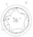
- Fig. 2 shows a plan view of the speaker unit according to the first embodiment of Fig. 1 ,
- the speaker unit 100 has a front first housing portion 60 of the housing, in which a woofer unit and a baffle 70 is received.
- a tweeter unit 30 is held by the tweeter 45.
- the tweeter unit 30 has webs 33 and recesses or recesses 31.
- Fig. 3 shows a schematic perspective view of the speaker unit according to the first embodiment.
- the speaker unit 100 has a rear housing 50 and a front, first housing section 60.
- the front first housing section 60 has a woofer unit 10 which is sunk in a baffle 70.
- a spacer unit 40 is provided in the middle of the woofer unit 10 and serves to receive a tweeter unit 30, wherein the tweeter 45 can be received in a hole 32 of the tweeter unit 30.
- the tweeter unit 30 or the tweeter horn has webs 33 and recesses or recesses 31.
- Fig. 4 shows a sectional view of a speaker unit according to the first embodiment.
- the loudspeaker unit has a front first housing section 60 with a baffle 70 and a recessed low-frequency unit 10.
- a spacer unit 40 is provided which can receive a tweeter unit 30.
- the tweeter unit 30 has a central opening 32.
- the tweeter unit 30 further includes a plurality of webs 33 and recesses 31.
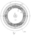
- Fig. 5 shows a schematic plan view of a speaker unit according to the first embodiment.
- the Hochtonhorn 30 has recesses 31 and webs 33 at the edge.
- an inner circle 100 is shown, which adjoins with its circumference 100 at the lower ends of the recesses 31, ie, the inner diameter of the reference surface is defined by the depth of the recesses.
- an outer circle 200 for limiting the reference surface can be provided, which corresponds to the outer diameter of the webs 33, ie the outer diameter of the reference surface.
- the outer circle 200 corresponds to the circumference of the Hochtonhornes 30.
- the ratio between the surface 300 of the recesses 31 with respect to the reference surface 400 between the inner and outer diameter 100, 200 is between 30% and 70%, in particular between 40% and 50% and 46% are preferred.
- the high frequency horn 30 has an inner diameter 100, which is defined by the depth of the recesses 31.
- the high frequency horn 30 also has an outer diameter 200, which is defined by the length of the webs 33.
- a reference surface 400 represents the area between the inner diameter 100 and the outer diameter 200.
- the design of the tweeter unit with the high-frequency horn is advantageous, because thus a broader beam angle can be achieved with low interference between the woofer unit and the tweeter unit.
- a spacer unit 40 for receiving the high-frequency unit 30 is located in front of the low-frequency unit 10, so that the high-frequency unit 30 is provided in the sound exit direction behind the low-frequency unit 10.
- the cross section of the free end of the tweeter unit 30 is greater than the cross section of the free end of the woofer unit 10.
- the area of the tweeter unit 30 is larger than the area of the woofer unit 10.
- a tweeter 45 may be arranged in front of the woofer unit 10, ie the tweeter 45 is disposed opposite to the sound exit direction in front of the woofer unit 10.
Landscapes
- Health & Medical Sciences (AREA)
- Otolaryngology (AREA)
- Physics & Mathematics (AREA)
- Engineering & Computer Science (AREA)
- Acoustics & Sound (AREA)
- Signal Processing (AREA)
- Obtaining Desirable Characteristics In Audible-Bandwidth Transducers (AREA)
Abstract
Description
- Die vorliegende Erfindung betrifft eine Lautsprechereinheit, insbesondere eine Deckenlautsprechereinheit.
- Deckenlautsprecher sind typischerweise als 2-Weg-Koaxial-System aufgebaut. Ein Hochtöner wird auf der gleichen Achse wie ein Tieftöner vor dem Tieftöner vorgesehen. Bei derartigen Lautsprechern kann es jedoch im Mitten- und Höhenbereich zu einer relativ eng gebündelten Abstrahlung kommen. Dies kann zur Folge haben, dass ein Klangeindruck relativ zu der Position des Hörers zu der Position des Deckenlautsprechers als unterschiedlich empfunden werden kann. Ein Deckenlautsprecher weist typischerweise einen Öffnungswinkel von 40 - 50° auf. Breitere Abstrahlwinkel führen oftmals zu Störungen zwischen Tief- und Hochtöner, die den Klangeindruck zusätzlich verschlechtern können.
-
DE 102 30 409 C1 zeigt eine Lautsprecheranordnung mit einem Tiefton-Lautsprecher und einem Hochton-Lautsprecher, der aus der Lautsprecheranordnung herausragt. - Es ist eine Aufgabe der vorliegenden Erfindung, eine Lautsprechereinheit mit einem 2-Weg-System vorzusehen, welche einen breiteren Öffnungswinkel aufweist und dabei Störungen zwischen beiden Lautsprechersystemen reduziert.
- Diese Aufgabe wird durch eine Lautsprechereinheit gemäß Anspruch 1 gelöst.
- Somit wird eine Lautsprechereinheit, insbesondere eine Deckenlautsprechereinheit, vorgesehen, welche ein Gehäuse mit einem vorderen Gehäuseabschnitt aufweist. In dem vorderen Gehäuseabschnitt ist eine Tieftoneinheit, eine Schallwand und eine Hochtoneinheit in einem 2-Wege-Koaxial-System angeordnet. Die Hochtoneinheit weist eine Mehrzahl von Stegen und eine Mehrzahl von Ausnehmungen am Rand der Hochtoneinheit auf.
- Gemäß einem Aspekt der vorliegenden Erfindung ist der Anteil der Flächen der Ausnehmungen bezogen auf eine Referenzfläche 30 % bis 70 % und insbesondere 40 % bis 50 %. Die Referenzfläche wird durch einen Innendurchmesser und einen Aussendurchmesser des Hochtonhornes definiert. Der Innendurchmesser wird durch die Tiefe der Ausnehmungen begrenzt und der Aussendurchmesser wird durch die freistehenden Enden der Stege begrenzt.
- Gemäß einem weiteren Aspekt der vorliegenden Erfindung erstrecken sich die Stege der Hochtoneinheit im Wesentlichen bis zum Rand der Schallwand.
- Gemäß einem weiteren Aspekt der vorliegenden Erfindung ist die Tieftoneinheit versenkt in der Schallwand angeordnet.
- Die Erfindung beruht auf dem Gedanken, eine Hochtoneinheit vor einem vertieft angeordneten Tieftöner anzuordnen, wobei die Hochtoneinheit Öffnungen an ihrem Rand aufweist.
- Durch die Ausgestaltungen der Öffnungen oder Ausnehmungen am Rand der Hochtoneinheit kann der Tieftonanteil der hinter der Hochtoneinheit liegenden Tieftoneinheit verbessert abgestrahlt werden.
- Weitere Ausgestaltungen der Erfindung sind Gegenstand der Unteransprüche.
- Vorteile und Ausführungsbeispiele der Erfindung werden nachstehend unter Bezugnahme auf die Zeichnung näher erläutert.
- Fig. 1
- zeigt eine perspektivische Ansicht einer Lautsprechereinheit gemäß einem ersten Ausführungsbeispiel,
- Fig. 2
- zeigt eine Draufsicht auf eine Lautsprechereinheit gemäß einem ersten Ausführungsbeispiel,
- Fig. 3
- zeigt eine perspektivische Ansicht einer Lautsprechereinheit gemäß dem ersten Ausführungsbeispiel,
- Fig. 4
- zeigt eine Schnittansicht einer Lautsprechereinheit gemäß dem ersten Ausführungsbeispiel und
- Fig. 5
- zeigt eine perspektivische Draufsicht auf eine Lautsprechereinheit gemäß dem ersten Ausführungsbeispiel.
-
Fig. 1 zeigt eine perspektivische Ansicht einer Lautsprechereinheit gemäß einem ersten Ausführungsbeispiel. Die Lautsprechereinheit 100 weist einen vorderen ersten Gehäuseabschnitt 60 und ein rückwärtiges Gehäuse 50, bzw. einen zweiten Gehäuseabschnitt auf. Der vordere erste Gehäuseabschnitt 60 weist eine Tieftoneinheit 10, eine Hochtoneinheit 30 und eine Schallwand 70 auf, wobei die Tieftoneinheit 10 und die Hochtoneinheit 30 als ein 2-Weg-Koaxial-System aufgebaut ist. Die Hochtoneinheit 30 ist dabei axial vor der Tieftoneinheit 10 angeordnet. Vorzugsweise ist die Tieftoneinheit 10 versetzt bzw. versenkt in einer Schallwand 70 angeordnet. Die Hochtoneinheit 30 kann auch ein Waveguide oder ein Hochtonhorn 30 aufweisen. Am Rand der Hochtoneinheit 30 bzw. des Hochtonhorns sind Ausnehmungen, Aussparungen oder Löcher 31 vorgesehen. Zwischen den Ausnehmungen 31 sind Stege 33 vorgesehen. Die Hochtoneinheit 30, 45 weist in der Mitte ein Loch 32 auf, in welches der Hochtöner 45 eingeführt werden kann. Das Hochtonhorn 30 wird somit an dem Hochtöner 45 befestigt. Die Stege 33 werden dabei nicht an der Schallwand 70 befestigt, sondern erstrecken sich frei im Raum. - Durch die Ausgestaltung der Hochtoneinheit 30 wird die Tieftoneinheit 10 im Wesentlichen abgedeckt. Eine Ausnahme dabei stellen lediglich die Ausnehmungen 31 dar, welche es der Tieftoneinheit 10 ermöglichen, tiefe Frequenzen weitgehend ungehindert abzustrahlen.
- Dies hat den Vorteil, dass die gegenseitige Beeinflussung zwischen der Tieftoneinheit 10 und der Hochtoneinheit 30 sehr gering ist. Vorzugsweise wird die Tieftoneinheit 10 versenkt in der Schallwand 70 vorgesehen. Es sei darauf hingewiesen, dass der Schall der Tieftoneinheit über die Ausnehmungen, Aussparungen oder Löcher am Rand der Hochtoneinheit entweichen bzw. abgestrahlt werden kann.
- Obwohl in
Fig. 1 kreisabschnittförmige oder ovale Ausnehmungen gezeigt sind, können die Ausnehmungen auch eine andere Form wie beispielsweise rechteckig, dreieckig oder dergleichen annehmen. - Die Einheit 40 stellt eine Abstandshalteeinheit mit aufgesetztem Hochtöner 45 dar, welche auf dem Polkern des Tieftöners befestigt werden kann.
-
Fig. 2 zeigt eine Draufsicht auf die Lautsprechereinheit gemäß dem ersten Ausführungsbeispiel vonFig. 1 . Die Lautsprechereinheit 100 weist einen vorderen ersten Gehäuseabschnitt 60 des Gehäuses auf, in welchem eine Tieftoneinheit und eine Schallwand 70 aufgenommen wird. Eine Hochtoneinheit 30 wird mittels des Hochtöners 45 gehalten. Die Hochtoneinheit 30 weist Stege 33 sowie Ausnehmungen bzw. Aussparungen 31 auf. -
Fig. 3 zeigt eine schematische perspektivische Ansicht der Lautsprechereinheit gemäß dem ersten Ausführungsbeispiel. Die Lautsprechereinheit 100 weist ein hinteres Gehäuse 50 sowie einen vorderen, ersten Gehäuseabschnitt 60 auf. Der vordere erste Gehäuseabschnitt 60 weist eine Tieftoneinheit 10 auf, welche versenkt in einer Schallwand 70 angeordnet ist. Eine Abstandshalteeinheit 40 ist in der Mitte der Tieftoneinheit 10 vorgesehen und dient dazu, eine Hochtoneinheit 30 aufzunehmen, wobei der Hochtöner 45 in einem Loch 32 der Hochtoneinheit 30 aufgenommen werden kann. Die Hochtoneinheit 30 bzw. das Hochtonhorn weist Stege 33 und Ausnehmungen bzw. Aussparungen 31 auf. -
Fig. 4 zeigt eine Schnittansicht einer Lautsprechereinheit gemäß dem ersten Ausführungsbeispiel. Die Lautsprechereinheit weist einen vorderen ersten Gehäuseabschnitt 60 mit einer Schallwand 70 sowie einer versenkt angeordneten Tieftoneinheit 10 auf. In der Mitte der Tieftoneinheit 10 ist eine Abstandshalteeinheit 40 vorgesehen, welche eine Hochtoneinheit 30 aufnehmen kann. Dazu weist die Hochtoneinheit 30 eine zentrale Öffnung 32 auf. Die Hochtoneinheit 30 weist ferner eine Vielzahl von Stegen 33 sowie Ausnehmungen 31 auf. -
Fig. 5 zeigt eine schematische Draufsicht auf eine Lautsprechereinheit gemäß dem ersten Ausführungsbeispiel. Das Hochtonhorn 30 weist Ausnehmungen 31 und Stege 33 am Rand auf. Zur Definition der Flächen 300 der Ausnehmungen bezogen auf eine Vergleichsfläche bzw. Referenzfläche 400 wird ein innerer Kreis 100 dargestellt, welcher mit seinem Umfang 100 an die unteren Enden der Ausnehmungen 31 angrenzt d. h. der Innendurchmesser der Referenzfläche wird durch die Tiefe der Ausnehmungen definiert. Ferner kann ein äußerer Kreis 200 zur Begrenzung der Referenzfläche vorgesehen werden, welcher dem Aussendurchmesser der Stege 33 entspricht, d. h. dem Aussendurchmesser der Referenzfläche. Der äußere Kreis 200 entspricht dem Umfang des Hochtonhornes 30. Das Verhältnis zwischen der Fläche 300 der Ausnehmungen 31 bezogen auf die Referenzfläche 400 zwischen dem inneren und äußeren Durchmesser 100, 200 beträgt zwischen 30 % und 70 %, insbesondere zwischen 40 % und 50 % und bevorzugt werden 46 %. Mit anderen Worten, das Hochtonhorn 30 weist einen Innendurchmesser 100 auf, welcher durch die Tiefe der Ausnehmungen 31 definiert ist. Das Hochtonhorn 30 weist ferner einen Aussendurchmesser 200 auf, welcher durch die Länge der Stege 33 definiert ist. Eine Referenzfläche 400 stellt dabei die Fläche zwischen dem Innendurchmesser 100 und dem Aussendurchmesser 200 dar. - Die Ausgestaltung der Hochtoneinheit mit dem Hochtonhorn ist vorteilhaft, weil somit ein breiterer Abstrahlwinkel bei geringen Störungen zwischen der Tieftoneinheit und der Hochtoneinheit erreicht werden kann.
- Wie in
Fig. 4 gezeigt, befindet sich eine Abstandshalteeinheit 40 zur Aufnahme der Hochtoneinheit 30 vor der Tieftoneinheit 10, so dass die Hochtoneinheit 30 in Schallaustrittsrichtung hinter der Tieftoneinheit 10 vorgesehen ist. Der Querschnitt des freien Endes der Hochtoneinheit 30 ist größer als der Querschnitt des freien Endes der Tieftoneinheit 10. Mit anderen Worten, die Fläche der Hochtoneinheit 30 ist größer als die Fläche der Tieftoneinheit 10. Ferner kann ein Hochtöner 45 vor der Tieftoneinheit 10 angeordnet sein, d.h. der Hochtöner 45 ist entgegen der Schallaustrittsrichtung vor der Tieftoneinheit 10 angeordnet.
Claims (5)
- Lautsprechereinheit, insbesondere Deckenlautsprechereinheit, mit
einem Gehäuse (50) mit einem ersten Gehäuseabschnitt (60), wobei in dem ersten Gehäuseabschnitt (60) eine Tieftoneinheit (10), eine Schallwand (70) und eine Hochtoneinheit (30) in einem 2-Wege-Koaxial-System vorgesehen sind,
wobei die Hochtoneinheit (30) ein Hochtonhorn mit einer Mehrzahl von Stegen (33) und einer Mehrzahl von Ausnehmungen (31) am Rand des Hochtonhorns (30) aufweist,
wobei die Tieftoneinheit (10) und die Hochtoneinheit (30) versenkt in der Schallwand (70) angeordnet sind. - Lautsprechereinheit nach Anspruch 1, wobei der Anteil der Flächen (300) der Ausnehmungen (31) bezogen auf eine Referenzfläche (400) 30 % bis 70 %, insbesondere 40 % bis 50 % beträgt,
wobei die Referenzfläche (400) durch einen Innendurchmesser (100) und einen Aussendurchmesser (200) des Hochtonhornes definiert wird,
wobei der Innendurchmesser (100) durch die Tiefe der Ausnehmungen (31) begrenzt wird,
wobei der Aussendurchmesser (200) durch die freistehenden Enden der Stege (33) begrenzt wird. - Lautsprechereinheit nach Anspruch 1 oder 2, wobei die Stege (33) der Hochtoneinheit (30) sich im Wesentlichen bis zum Rand der Schallwand (70) erstrecken.
- Lautsprechereinheit nach einem der Ansprüche 1 bis 3, wobei der Querschnitt der Hochtoneinheit (30) größer ist als der Querschnitt der Tieftoneinheit (10).
- Lautsprechereinheit nach einem der Ansprüche 1 bis 4, wobei ein Hochtöner (45) vor der Tieftoneinheit (10) angeordnet ist.
Applications Claiming Priority (1)
| Application Number | Priority Date | Filing Date | Title |
|---|---|---|---|
| DE102008058028A DE102008058028A1 (de) | 2008-11-18 | 2008-11-18 | Lautsprechereinheit |
Publications (3)
| Publication Number | Publication Date |
|---|---|
| EP2187659A2 true EP2187659A2 (de) | 2010-05-19 |
| EP2187659A3 EP2187659A3 (de) | 2012-10-03 |
| EP2187659B1 EP2187659B1 (de) | 2015-05-13 |
Family
ID=41691582
Family Applications (1)
| Application Number | Title | Priority Date | Filing Date |
|---|---|---|---|
| EP20090175670 Active EP2187659B1 (de) | 2008-11-18 | 2009-11-11 | Lautsprechereinheit |
Country Status (3)
| Country | Link |
|---|---|
| US (1) | US8503690B2 (de) |
| EP (1) | EP2187659B1 (de) |
| DE (1) | DE102008058028A1 (de) |
Cited By (1)
| Publication number | Priority date | Publication date | Assignee | Title |
|---|---|---|---|---|
| CN104378717A (zh) * | 2014-10-30 | 2015-02-25 | 歌尔声学股份有限公司 | 一种高音扬声器及一种实现全指向高音声场的方法 |
Families Citing this family (9)
| Publication number | Priority date | Publication date | Assignee | Title |
|---|---|---|---|---|
| US8467557B2 (en) * | 2009-09-24 | 2013-06-18 | MS Electronics LLC | Coaxial speaker system with improved transition between individual speakers |
| JP1526064S (de) * | 2014-12-25 | 2015-06-15 | ||
| US9800968B2 (en) * | 2015-05-13 | 2017-10-24 | Paradigm Electronics Inc. | Low diffraction tweeter housing |
| DK201770717A1 (en) | 2016-09-23 | 2018-04-03 | Tymphany Hk Ltd | Loudspeaker assembly |
| US10341761B2 (en) * | 2017-02-17 | 2019-07-02 | Tymphany Hk Limited | Acoustic waveguide for audio speaker |
| USD873795S1 (en) * | 2017-08-02 | 2020-01-28 | Spirit, LLC | Speaker |
| US11490194B1 (en) * | 2021-08-18 | 2022-11-01 | Harman Professional, Inc. | Omnidirectional speaker with an inverted dome diaphragm and asymmetric vertical directivity response |
| JP7704001B2 (ja) * | 2021-10-26 | 2025-07-08 | ヤマハ株式会社 | 同軸スピーカ用のホーン、及び、同軸スピーカ |
| CN119383501A (zh) * | 2024-10-17 | 2025-01-28 | 浙江未来精灵人工智能科技有限公司 | 音箱 |
Citations (1)
| Publication number | Priority date | Publication date | Assignee | Title |
|---|---|---|---|---|
| DE10230409C1 (de) | 2002-07-05 | 2003-10-09 | D & B Audiotechnik Ag | Koaxiale Lautsprecheranordnung mit rotierbarem Horn |
Family Cites Families (11)
| Publication number | Priority date | Publication date | Assignee | Title |
|---|---|---|---|---|
| BE366478A (de) * | 1929-07-26 | |||
| US5193119A (en) * | 1985-09-02 | 1993-03-09 | Franco Tontini | Multiple loudspeaker |
| US5143339A (en) * | 1991-03-01 | 1992-09-01 | Jbl, Incorporated | Speaker mounting assembly |
| CA2048954C (en) * | 1991-08-12 | 2002-07-16 | Leopold A. Lewis | Speaker box |
| US6792125B1 (en) * | 2000-08-23 | 2004-09-14 | Boston Acoustics, Inc. | Pivotable speaker mounting apparatus |
| US7142680B2 (en) * | 2003-03-31 | 2006-11-28 | Telex | Multiple waveguide coaxial ceiling loudspeaker |
| US7570778B2 (en) * | 2003-08-26 | 2009-08-04 | Wright Doug S | Angled speaker assembly |
| DE10341213B4 (de) * | 2003-09-04 | 2006-04-13 | Don't Panic Die Case-Manufactur Gmbh | Schalldiffusoranordnung für ein Lautsprechersystem |
| JP2005184040A (ja) * | 2003-12-15 | 2005-07-07 | Sony Corp | 音声信号処理装置及び音声信号再生システム |
| US7684585B2 (en) * | 2006-01-31 | 2010-03-23 | Alpine Electronics, Inc. | Thermal management system for speaker system having vented frame for establishing air passages |
| JP4839890B2 (ja) * | 2006-02-28 | 2011-12-21 | ヤマハ株式会社 | 広指向性スピーカシステム |
-
2008
- 2008-11-18 DE DE102008058028A patent/DE102008058028A1/de not_active Withdrawn
-
2009
- 2009-11-11 EP EP20090175670 patent/EP2187659B1/de active Active
- 2009-11-17 US US12/620,193 patent/US8503690B2/en not_active Expired - Fee Related
Patent Citations (1)
| Publication number | Priority date | Publication date | Assignee | Title |
|---|---|---|---|---|
| DE10230409C1 (de) | 2002-07-05 | 2003-10-09 | D & B Audiotechnik Ag | Koaxiale Lautsprecheranordnung mit rotierbarem Horn |
Cited By (2)
| Publication number | Priority date | Publication date | Assignee | Title |
|---|---|---|---|---|
| CN104378717A (zh) * | 2014-10-30 | 2015-02-25 | 歌尔声学股份有限公司 | 一种高音扬声器及一种实现全指向高音声场的方法 |
| CN104378717B (zh) * | 2014-10-30 | 2016-09-28 | 歌尔股份有限公司 | 一种高音扬声器及一种实现全指向高音声场的方法 |
Also Published As
| Publication number | Publication date |
|---|---|
| DE102008058028A1 (de) | 2010-05-20 |
| EP2187659A3 (de) | 2012-10-03 |
| EP2187659B1 (de) | 2015-05-13 |
| US20100124340A1 (en) | 2010-05-20 |
| US8503690B2 (en) | 2013-08-06 |
Similar Documents
| Publication | Publication Date | Title |
|---|---|---|
| EP2187659B1 (de) | Lautsprechereinheit | |
| EP3025394B1 (de) | Breitbandige omnidirektionale antenne | |
| DE102008010524B4 (de) | Lautsprecherbox mit variabler Abstrahlcharakteristik | |
| DE202013104388U1 (de) | Einsteckkopfhörer | |
| DE102016119005A1 (de) | Elektroakustischer Wandler | |
| EP3610478B1 (de) | Körperschallaktuator für ein kraftfahrzeug und kraftfahrzeug | |
| DE102021104847B4 (de) | Lautsprecherhorn mit drehbarem abstrahlverhalten, lautsprecheranordnung und lautsprecherbox | |
| DE3637910C2 (de) | ||
| EP0152926A2 (de) | Elektrodynamischer Lautsprecher mit Rundum-Schallabstrahlung | |
| EP0615398B1 (de) | Elektroakustischer Wandler mit einer Maske | |
| DE212013000301U1 (de) | Hornförmige Multipoint-Anregungslautsprecherbox | |
| EP2792161A1 (de) | Lautsprechergehäuse | |
| DE102021103379B3 (de) | Resonatoreinsatz zum Einsetzen in einen Ansaugstutzen eines Turboladers, Turbolader und Resonator | |
| DE102018116681A1 (de) | Vorrichtung sowie Verfahren zur Reduktion einer Schallleistung einer Schallquelle | |
| EP4123205B1 (de) | Leitungsdurchführung | |
| EP1125471B1 (de) | Mikrofon | |
| DE102019120140B3 (de) | Elektrodynamischer Lautsprecher | |
| WO2000038474A2 (de) | Tiefton-membranlautsprecher | |
| EP3217085B1 (de) | Leuchtenrahmen | |
| DE102006051613B4 (de) | Lautsprechergehäuse | |
| DE202010015807U1 (de) | Verbindung einer insbesondere mit einem Ritzel versehenen Hohlwelle mit einer in sie einsetzbaren Welle oder Achse | |
| DE19650522C2 (de) | Kegelförmiger Lautsprechervorsatz | |
| DE10052657C2 (de) | Korbspule für Draht, insbesondere für Schweißdraht | |
| DE102011056710A1 (de) | Koaxiales elektrisches Übertragungselement | |
| DE4022370A1 (de) | Integrierte fernsehlautsprecherbox |
Legal Events
| Date | Code | Title | Description |
|---|---|---|---|
| PUAI | Public reference made under article 153(3) epc to a published international application that has entered the european phase |
Free format text: ORIGINAL CODE: 0009012 |
|
| AK | Designated contracting states |
Kind code of ref document: A2 Designated state(s): AT BE BG CH CY CZ DE DK EE ES FI FR GB GR HR HU IE IS IT LI LT LU LV MC MK MT NL NO PL PT RO SE SI SK SM TR |
|
| AX | Request for extension of the european patent |
Extension state: AL BA RS |
|
| RAP1 | Party data changed (applicant data changed or rights of an application transferred) |
Owner name: SENNHEISER ELECTRONIC GMBH & CO. KG |
|
| REG | Reference to a national code |
Ref country code: DE Ref legal event code: R079 Ref document number: 502009011022 Country of ref document: DE Free format text: PREVIOUS MAIN CLASS: H04R0009060000 Ipc: H04R0001240000 |
|
| PUAL | Search report despatched |
Free format text: ORIGINAL CODE: 0009013 |
|
| AK | Designated contracting states |
Kind code of ref document: A3 Designated state(s): AT BE BG CH CY CZ DE DK EE ES FI FR GB GR HR HU IE IS IT LI LT LU LV MC MK MT NL NO PL PT RO SE SI SK SM TR |
|
| AX | Request for extension of the european patent |
Extension state: AL BA RS |
|
| RIC1 | Information provided on ipc code assigned before grant |
Ipc: H04R 1/24 20060101AFI20120829BHEP Ipc: H04R 1/34 20060101ALI20120829BHEP |
|
| 17P | Request for examination filed |
Effective date: 20121113 |
|
| 17Q | First examination report despatched |
Effective date: 20130114 |
|
| GRAP | Despatch of communication of intention to grant a patent |
Free format text: ORIGINAL CODE: EPIDOSNIGR1 |
|
| INTG | Intention to grant announced |
Effective date: 20150108 |
|
| GRAS | Grant fee paid |
Free format text: ORIGINAL CODE: EPIDOSNIGR3 |
|
| GRAA | (expected) grant |
Free format text: ORIGINAL CODE: 0009210 |
|
| AK | Designated contracting states |
Kind code of ref document: B1 Designated state(s): AT BE BG CH CY CZ DE DK EE ES FI FR GB GR HR HU IE IS IT LI LT LU LV MC MK MT NL NO PL PT RO SE SI SK SM TR |
|
| REG | Reference to a national code |
Ref country code: GB Ref legal event code: FG4D Free format text: NOT ENGLISH |
|
| REG | Reference to a national code |
Ref country code: CH Ref legal event code: EP |
|
| REG | Reference to a national code |
Ref country code: IE Ref legal event code: FG4D Free format text: LANGUAGE OF EP DOCUMENT: GERMAN |
|
| REG | Reference to a national code |
Ref country code: AT Ref legal event code: REF Ref document number: 727193 Country of ref document: AT Kind code of ref document: T Effective date: 20150615 |
|
| REG | Reference to a national code |
Ref country code: DE Ref legal event code: R096 Ref document number: 502009011022 Country of ref document: DE Effective date: 20150625 |
|
| REG | Reference to a national code |
Ref country code: NL Ref legal event code: MP Effective date: 20150513 |
|
| REG | Reference to a national code |
Ref country code: LT Ref legal event code: MG4D |
|
| PG25 | Lapsed in a contracting state [announced via postgrant information from national office to epo] |
Ref country code: FI Free format text: LAPSE BECAUSE OF FAILURE TO SUBMIT A TRANSLATION OF THE DESCRIPTION OR TO PAY THE FEE WITHIN THE PRESCRIBED TIME-LIMIT Effective date: 20150513 Ref country code: PT Free format text: LAPSE BECAUSE OF FAILURE TO SUBMIT A TRANSLATION OF THE DESCRIPTION OR TO PAY THE FEE WITHIN THE PRESCRIBED TIME-LIMIT Effective date: 20150914 Ref country code: NO Free format text: LAPSE BECAUSE OF FAILURE TO SUBMIT A TRANSLATION OF THE DESCRIPTION OR TO PAY THE FEE WITHIN THE PRESCRIBED TIME-LIMIT Effective date: 20150813 Ref country code: ES Free format text: LAPSE BECAUSE OF FAILURE TO SUBMIT A TRANSLATION OF THE DESCRIPTION OR TO PAY THE FEE WITHIN THE PRESCRIBED TIME-LIMIT Effective date: 20150513 Ref country code: HR Free format text: LAPSE BECAUSE OF FAILURE TO SUBMIT A TRANSLATION OF THE DESCRIPTION OR TO PAY THE FEE WITHIN THE PRESCRIBED TIME-LIMIT Effective date: 20150513 Ref country code: LT Free format text: LAPSE BECAUSE OF FAILURE TO SUBMIT A TRANSLATION OF THE DESCRIPTION OR TO PAY THE FEE WITHIN THE PRESCRIBED TIME-LIMIT Effective date: 20150513 |
|
| REG | Reference to a national code |
Ref country code: FR Ref legal event code: PLFP Year of fee payment: 7 |
|
| PG25 | Lapsed in a contracting state [announced via postgrant information from national office to epo] |
Ref country code: LV Free format text: LAPSE BECAUSE OF FAILURE TO SUBMIT A TRANSLATION OF THE DESCRIPTION OR TO PAY THE FEE WITHIN THE PRESCRIBED TIME-LIMIT Effective date: 20150513 Ref country code: BG Free format text: LAPSE BECAUSE OF FAILURE TO SUBMIT A TRANSLATION OF THE DESCRIPTION OR TO PAY THE FEE WITHIN THE PRESCRIBED TIME-LIMIT Effective date: 20150813 Ref country code: IS Free format text: LAPSE BECAUSE OF FAILURE TO SUBMIT A TRANSLATION OF THE DESCRIPTION OR TO PAY THE FEE WITHIN THE PRESCRIBED TIME-LIMIT Effective date: 20150913 Ref country code: GR Free format text: LAPSE BECAUSE OF FAILURE TO SUBMIT A TRANSLATION OF THE DESCRIPTION OR TO PAY THE FEE WITHIN THE PRESCRIBED TIME-LIMIT Effective date: 20150814 |
|
| PG25 | Lapsed in a contracting state [announced via postgrant information from national office to epo] |
Ref country code: DK Free format text: LAPSE BECAUSE OF FAILURE TO SUBMIT A TRANSLATION OF THE DESCRIPTION OR TO PAY THE FEE WITHIN THE PRESCRIBED TIME-LIMIT Effective date: 20150513 Ref country code: EE Free format text: LAPSE BECAUSE OF FAILURE TO SUBMIT A TRANSLATION OF THE DESCRIPTION OR TO PAY THE FEE WITHIN THE PRESCRIBED TIME-LIMIT Effective date: 20150513 |
|
| REG | Reference to a national code |
Ref country code: DE Ref legal event code: R097 Ref document number: 502009011022 Country of ref document: DE |
|
| PG25 | Lapsed in a contracting state [announced via postgrant information from national office to epo] |
Ref country code: PL Free format text: LAPSE BECAUSE OF FAILURE TO SUBMIT A TRANSLATION OF THE DESCRIPTION OR TO PAY THE FEE WITHIN THE PRESCRIBED TIME-LIMIT Effective date: 20150513 Ref country code: RO Free format text: LAPSE BECAUSE OF NON-PAYMENT OF DUE FEES Effective date: 20150513 Ref country code: CZ Free format text: LAPSE BECAUSE OF FAILURE TO SUBMIT A TRANSLATION OF THE DESCRIPTION OR TO PAY THE FEE WITHIN THE PRESCRIBED TIME-LIMIT Effective date: 20150513 Ref country code: SK Free format text: LAPSE BECAUSE OF FAILURE TO SUBMIT A TRANSLATION OF THE DESCRIPTION OR TO PAY THE FEE WITHIN THE PRESCRIBED TIME-LIMIT Effective date: 20150513 |
|
| PLBE | No opposition filed within time limit |
Free format text: ORIGINAL CODE: 0009261 |
|
| STAA | Information on the status of an ep patent application or granted ep patent |
Free format text: STATUS: NO OPPOSITION FILED WITHIN TIME LIMIT |
|
| 26N | No opposition filed |
Effective date: 20160216 |
|
| PG25 | Lapsed in a contracting state [announced via postgrant information from national office to epo] |
Ref country code: IT Free format text: LAPSE BECAUSE OF FAILURE TO SUBMIT A TRANSLATION OF THE DESCRIPTION OR TO PAY THE FEE WITHIN THE PRESCRIBED TIME-LIMIT Effective date: 20150513 |
|
| PG25 | Lapsed in a contracting state [announced via postgrant information from national office to epo] |
Ref country code: SI Free format text: LAPSE BECAUSE OF FAILURE TO SUBMIT A TRANSLATION OF THE DESCRIPTION OR TO PAY THE FEE WITHIN THE PRESCRIBED TIME-LIMIT Effective date: 20150513 |
|
| PG25 | Lapsed in a contracting state [announced via postgrant information from national office to epo] |
Ref country code: LU Free format text: LAPSE BECAUSE OF FAILURE TO SUBMIT A TRANSLATION OF THE DESCRIPTION OR TO PAY THE FEE WITHIN THE PRESCRIBED TIME-LIMIT Effective date: 20151111 Ref country code: MC Free format text: LAPSE BECAUSE OF FAILURE TO SUBMIT A TRANSLATION OF THE DESCRIPTION OR TO PAY THE FEE WITHIN THE PRESCRIBED TIME-LIMIT Effective date: 20150513 |
|
| REG | Reference to a national code |
Ref country code: CH Ref legal event code: PL |
|
| PG25 | Lapsed in a contracting state [announced via postgrant information from national office to epo] |
Ref country code: CH Free format text: LAPSE BECAUSE OF NON-PAYMENT OF DUE FEES Effective date: 20151130 Ref country code: LI Free format text: LAPSE BECAUSE OF NON-PAYMENT OF DUE FEES Effective date: 20151130 |
|
| REG | Reference to a national code |
Ref country code: IE Ref legal event code: MM4A |
|
| PG25 | Lapsed in a contracting state [announced via postgrant information from national office to epo] |
Ref country code: IE Free format text: LAPSE BECAUSE OF NON-PAYMENT OF DUE FEES Effective date: 20151111 |
|
| REG | Reference to a national code |
Ref country code: FR Ref legal event code: PLFP Year of fee payment: 8 |
|
| REG | Reference to a national code |
Ref country code: AT Ref legal event code: MM01 Ref document number: 727193 Country of ref document: AT Kind code of ref document: T Effective date: 20151111 |
|
| PG25 | Lapsed in a contracting state [announced via postgrant information from national office to epo] |
Ref country code: AT Free format text: LAPSE BECAUSE OF NON-PAYMENT OF DUE FEES Effective date: 20151111 |
|
| PG25 | Lapsed in a contracting state [announced via postgrant information from national office to epo] |
Ref country code: SM Free format text: LAPSE BECAUSE OF FAILURE TO SUBMIT A TRANSLATION OF THE DESCRIPTION OR TO PAY THE FEE WITHIN THE PRESCRIBED TIME-LIMIT Effective date: 20150513 Ref country code: HU Free format text: LAPSE BECAUSE OF FAILURE TO SUBMIT A TRANSLATION OF THE DESCRIPTION OR TO PAY THE FEE WITHIN THE PRESCRIBED TIME-LIMIT; INVALID AB INITIO Effective date: 20091111 |
|
| PG25 | Lapsed in a contracting state [announced via postgrant information from national office to epo] |
Ref country code: CY Free format text: LAPSE BECAUSE OF FAILURE TO SUBMIT A TRANSLATION OF THE DESCRIPTION OR TO PAY THE FEE WITHIN THE PRESCRIBED TIME-LIMIT Effective date: 20150513 Ref country code: SE Free format text: LAPSE BECAUSE OF FAILURE TO SUBMIT A TRANSLATION OF THE DESCRIPTION OR TO PAY THE FEE WITHIN THE PRESCRIBED TIME-LIMIT Effective date: 20150513 Ref country code: NL Free format text: LAPSE BECAUSE OF FAILURE TO SUBMIT A TRANSLATION OF THE DESCRIPTION OR TO PAY THE FEE WITHIN THE PRESCRIBED TIME-LIMIT Effective date: 20150513 |
|
| PG25 | Lapsed in a contracting state [announced via postgrant information from national office to epo] |
Ref country code: BE Free format text: LAPSE BECAUSE OF NON-PAYMENT OF DUE FEES Effective date: 20151130 |
|
| PG25 | Lapsed in a contracting state [announced via postgrant information from national office to epo] |
Ref country code: TR Free format text: LAPSE BECAUSE OF FAILURE TO SUBMIT A TRANSLATION OF THE DESCRIPTION OR TO PAY THE FEE WITHIN THE PRESCRIBED TIME-LIMIT Effective date: 20150513 Ref country code: MT Free format text: LAPSE BECAUSE OF FAILURE TO SUBMIT A TRANSLATION OF THE DESCRIPTION OR TO PAY THE FEE WITHIN THE PRESCRIBED TIME-LIMIT Effective date: 20150513 |
|
| REG | Reference to a national code |
Ref country code: FR Ref legal event code: PLFP Year of fee payment: 9 |
|
| PG25 | Lapsed in a contracting state [announced via postgrant information from national office to epo] |
Ref country code: MK Free format text: LAPSE BECAUSE OF FAILURE TO SUBMIT A TRANSLATION OF THE DESCRIPTION OR TO PAY THE FEE WITHIN THE PRESCRIBED TIME-LIMIT Effective date: 20150513 |
|
| REG | Reference to a national code |
Ref country code: DE Ref legal event code: R081 Ref document number: 502009011022 Country of ref document: DE Owner name: SENNHEISER ELECTRONIC SE & CO. KG, DE Free format text: FORMER OWNER: SENNHEISER ELECTRONIC GMBH & CO. KG, 30900 WEDEMARK, DE |
|
| PGFP | Annual fee paid to national office [announced via postgrant information from national office to epo] |
Ref country code: DE Payment date: 20251107 Year of fee payment: 17 |
|
| PGFP | Annual fee paid to national office [announced via postgrant information from national office to epo] |
Ref country code: GB Payment date: 20251120 Year of fee payment: 17 |
|
| PGFP | Annual fee paid to national office [announced via postgrant information from national office to epo] |
Ref country code: FR Payment date: 20251120 Year of fee payment: 17 |