EP2187397A1 - Method and apparatus for erasure decoding an ECC coded bitstream - Google Patents
Method and apparatus for erasure decoding an ECC coded bitstream Download PDFInfo
- Publication number
- EP2187397A1 EP2187397A1 EP08305774A EP08305774A EP2187397A1 EP 2187397 A1 EP2187397 A1 EP 2187397A1 EP 08305774 A EP08305774 A EP 08305774A EP 08305774 A EP08305774 A EP 08305774A EP 2187397 A1 EP2187397 A1 EP 2187397A1
- Authority
- EP
- European Patent Office
- Prior art keywords
- clues
- error
- erasure
- positive
- clue
- Prior art date
- Legal status (The legal status is an assumption and is not a legal conclusion. Google has not performed a legal analysis and makes no representation as to the accuracy of the status listed.)
- Withdrawn
Links
Images


Classifications
-
- G—PHYSICS
- G11—INFORMATION STORAGE
- G11B—INFORMATION STORAGE BASED ON RELATIVE MOVEMENT BETWEEN RECORD CARRIER AND TRANSDUCER
- G11B20/00—Signal processing not specific to the method of recording or reproducing; Circuits therefor
- G11B20/10—Digital recording or reproducing
- G11B20/18—Error detection or correction; Testing, e.g. of drop-outs
-
- H—ELECTRICITY
- H03—ELECTRONIC CIRCUITRY
- H03M—CODING; DECODING; CODE CONVERSION IN GENERAL
- H03M5/00—Conversion of the form of the representation of individual digits
- H03M5/02—Conversion to or from representation by pulses
- H03M5/04—Conversion to or from representation by pulses the pulses having two levels
- H03M5/14—Code representation, e.g. transition, for a given bit cell depending on the information in one or more adjacent bit cells, e.g. delay modulation code, double density code
- H03M5/145—Conversion to or from block codes or representations thereof
-
- G—PHYSICS
- G11—INFORMATION STORAGE
- G11B—INFORMATION STORAGE BASED ON RELATIVE MOVEMENT BETWEEN RECORD CARRIER AND TRANSDUCER
- G11B20/00—Signal processing not specific to the method of recording or reproducing; Circuits therefor
- G11B20/10—Digital recording or reproducing
- G11B20/10009—Improvement or modification of read or write signals
- G11B20/10046—Improvement or modification of read or write signals filtering or equalising, e.g. setting the tap weights of an FIR filter
-
- G—PHYSICS
- G11—INFORMATION STORAGE
- G11B—INFORMATION STORAGE BASED ON RELATIVE MOVEMENT BETWEEN RECORD CARRIER AND TRANSDUCER
- G11B20/00—Signal processing not specific to the method of recording or reproducing; Circuits therefor
- G11B20/10—Digital recording or reproducing
- G11B20/14—Digital recording or reproducing using self-clocking codes
- G11B20/1403—Digital recording or reproducing using self-clocking codes characterised by the use of two levels
- G11B20/1423—Code representation depending on subsequent bits, e.g. delay modulation, double density code, Miller code
- G11B20/1426—Code representation depending on subsequent bits, e.g. delay modulation, double density code, Miller code conversion to or from block codes or representations thereof
-
- H—ELECTRICITY
- H03—ELECTRONIC CIRCUITRY
- H03M—CODING; DECODING; CODE CONVERSION IN GENERAL
- H03M13/00—Coding, decoding or code conversion, for error detection or error correction; Coding theory basic assumptions; Coding bounds; Error probability evaluation methods; Channel models; Simulation or testing of codes
- H03M13/03—Error detection or forward error correction by redundancy in data representation, i.e. code words containing more digits than the source words
- H03M13/05—Error detection or forward error correction by redundancy in data representation, i.e. code words containing more digits than the source words using block codes, i.e. a predetermined number of check bits joined to a predetermined number of information bits
-
- H—ELECTRICITY
- H03—ELECTRONIC CIRCUITRY
- H03M—CODING; DECODING; CODE CONVERSION IN GENERAL
- H03M13/00—Coding, decoding or code conversion, for error detection or error correction; Coding theory basic assumptions; Coding bounds; Error probability evaluation methods; Channel models; Simulation or testing of codes
- H03M13/29—Coding, decoding or code conversion, for error detection or error correction; Coding theory basic assumptions; Coding bounds; Error probability evaluation methods; Channel models; Simulation or testing of codes combining two or more codes or code structures, e.g. product codes, generalised product codes, concatenated codes, inner and outer codes
- H03M13/2954—Coding, decoding or code conversion, for error detection or error correction; Coding theory basic assumptions; Coding bounds; Error probability evaluation methods; Channel models; Simulation or testing of codes combining two or more codes or code structures, e.g. product codes, generalised product codes, concatenated codes, inner and outer codes using Picket codes or other codes providing error burst detection capabilities, e.g. burst indicator codes and long distance codes [LDC]
-
- G—PHYSICS
- G11—INFORMATION STORAGE
- G11B—INFORMATION STORAGE BASED ON RELATIVE MOVEMENT BETWEEN RECORD CARRIER AND TRANSDUCER
- G11B20/00—Signal processing not specific to the method of recording or reproducing; Circuits therefor
- G11B20/10—Digital recording or reproducing
- G11B20/14—Digital recording or reproducing using self-clocking codes
- G11B20/1403—Digital recording or reproducing using self-clocking codes characterised by the use of two levels
- G11B20/1423—Code representation depending on subsequent bits, e.g. delay modulation, double density code, Miller code
- G11B20/1426—Code representation depending on subsequent bits, e.g. delay modulation, double density code, Miller code conversion to or from block codes or representations thereof
- G11B2020/1457—Code representation depending on subsequent bits, e.g. delay modulation, double density code, Miller code conversion to or from block codes or representations thereof wherein DC control is performed by calculating a digital sum value [DSV]
Definitions
- the present invention relates to the technical field of error correction coding and decoding of digital data in a burst error environment, in particular to erasure decoding of digital data which comprise low frequency reduction data.
- error correction encoding is applied before channel coding on the recording side, and correspondingly error correction decoding is performed after channel decoding on the readout side.
- So-called block codes are one widely used class of error correction codes.
- Reed-Solomon codes are one example of block codes.
- This invention proposes to use, as the basis of erasure detection, redundancy which is present in a channel encoded data stream.
- erasure information is derived from redundancy contained in the bitstream.
- redundancy is meant to denote any form of constrainedness of data, in the sense of dependencies of some data from others. This kind of dependencies, when violated, allows to conclude at the readback side that a data error must be present, from which erasure information can be deducted or estimated, so that erasure detection is enabled.
- this invention describes a "bridging strategy", which can be interpreted as a nonlinear median filter-like postprocessing on the sequence of positive/negative clues viewed as a sequence of bits.
- the invention allows to generate erasure information without spending any additional redundancy for error detection. It does so by exploiting inherent redundancy of DC-control bits periodically inserted into the RLL modulated bitstream by a method proposed in EP 07107630 .
- the erasure information generated according to this invention can be used in a system where it constitutes the only kind of erasure information being used.
- the exemplary embodiment described in the following is such a system.
- the erasure information generated according to this invention can be used as a complement to other kinds of erasure information, derived from other sources. Having two kinds of erasure information stemming from different sources, or being generated in different ways, offers the advantage that by consolidating the two kinds of erasure information, e.g. by uniting them with some kind of majority vote, misclassifications can potentially be detected and eliminated.
- the erasure information generated according to this invention is particularly apt for being used as an additional or complementing erasure information, because its generation does not need any redundancy insertion, with other words there is no rate loss incurred.
- channel coding In digital data storage, channel coding, also denoted as channel modulation, is used to transform the digital data into a signal that is appropriate for the requirements of the storage channel.
- DC control One concept used in channel coding is denoted as “DC control” and comprises signal processing steps that influence the low frequency end of the spectrum of the signal.
- Signal regeneration on the storage readout side is facilitated if the signal being written onto a storage medium is “DC free”, with other words, if, at least on average, this signal contains as much of "pit” as of "space” in case of optical data storage, or as much of "plus” as of "minus” in the magnetic data storage case.
- the low frequency content of a signal is measured in that context by a so-called running digital sum, RDS.
- EP 07107630 describes methods and apparatuses for controlling the DC-content while channel encoding a sequence of digital data blocks.
- the data blocks are individually subdivided into a head part, a body part, and a tail part, each of varying length.
- Each tail part of a specific one of the data blocks, together with some inserted control bits and the head part of the subsequent one of the data blocks are grouped into a so-called control block.
- the sizes of the head and tail parts are dynamically chosen in such a way as to enable independent runlength limited encoding of the data block's body parts and of the control blocks.
- Control bit insertion comprizes a choice between a so-called “inverting" control bit pattern and a "preserving" control bit pattern, by which choice the RDS contribution of the body part can be inverted.
- EP 07107630 describes to exercise the choice in such a way as to minimize the DC content.
- Blu-ray disc uses a picket code scheme that locates erroneous symbols within the pickets. This information can be exploited in a certain way to declare erasure between erroneous pickets.
- the pickets are therefore also referred to as burst indicating subcode or BIS.
- each ECC frame consists of 4 pickets where the first picket is given by the sync words.
- erasure information within a stream of read out channel data bits is generated by checking the integrity of periodically inserted error locating clues between blocks of channel data bits. Blocks between error indicating (positive) clues within a certain distance are then declared to be erased.
- a clue consists of a number of channel data bits or other subchannel data bits provided with additional redundancy.
- Redundancy can be induced by parity checks, CRC, or any other error detection code or method. Also inherent redundancy, not primarily intended for error detection, induced by any other method, like DC-control bit insertion, might be used for integrity checks.
- a stream of channel data bits is assumed to be separated into blocks through periodically inserted sync patterns. It is further assumed that corruption of the sync patterns by error bursts will likely be detected.
- the preceding assumptions will allow erasure intervals to be declared within each sync block independently, but the principles of the invention will also be applicable if any of the assumptions does not hold.
- a sync block is separated into n channel data blocks through (n-1) erasure clues or clues.
- n-1 erasure clues or clues.
- the number of channel data bits per block will be much greater than the number of clue bits. This is symbolically illustrated in Fig. 2 by the broken lines. With other words: the number of clue bits is small against the number of channel data bits between any two consecutive clues.
- the invention aims at identifying bursts of errors through checking the integrity of the clues. Positive clues indicating integrity check failure are used to declare intervals of erasure. It is required that the clues can be self checkable, i.e. no other information than the clue itself is needed to tell if the clue has been corrupted or not. This is in contrast to the method described in US 6,378,100 , where clues are extracted from a multi-symbol codeword. US 6,378,100 derives error locative clues from the encoded clue words, hence some error locating process has to be involved. In the present invention, no error locating process is needed since clue locations are known.
- This invention uses a different approach, in that self checking clues are constructed without the use of extra redundancy, instead using inherent redundancy of periodically inserted subchannel or control structures as a clue.
- the redundancy induced by the method of DC-control bit insertion as given in EP 07107630 is exploited as self checking clue.
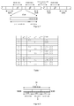
- Table 1 illustrates the DC-control bit insertion into a (1,7) RLL code according to EP 07107630 .
- the need to spend 2 DC-control bits to guarantee inversion or preservation of the differential RDS of the DC-control block a rose from only a few special combinations of data bits.
- every two DC control bits chosen according to EP 07107630 contain a redundancy of slightly less than one bit.
- the two DC-control bits shown in Table 1 as c i , at least in some cases depend on the two tail bits u i - 1 tail preceding them and on the subsequent two head bits u i head .
- the two tail bits, the two DC-control bits and the two head bits are concatenated in this order to yield a 6 bit clue.
- the specific dependency of the DC control bits as prescribed by EP 07107630 and as illustrated in Table 1, and individually listing the cases summarized in the "don't care" cells thereof, it turns out that among the 64 distinct values that exist for 6 bit words, 37 are negative clues indicating validity, and 27 are positive clues indicating invalidity. This means that the probability of finding any error is low. With other words, the redundancy is spread across the clue.
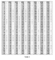
- Table 2 illustrates which of the 64 distinct values that exist for 6 bit erasure clues constitute valid clues, and which constitute invalid clues.
- the error detection probability can be further increased if, instead of two preceding data bits, four preceding data bits are taken into account.
- Figure 4 illustrates this variant of erasure clue construction.
- 133 constitute negative clues
- 123 constitute positive clues.
- Table 3 shows the resulting lookup table, i.e. it illustrates which of the 256 distinct values that exist for 8 bit erasure clues constitute valid clues, and which constitute invalid clues.
- Valid, i.e. negative clues are indicated by "1", invalid i.e. positive clues by "0".
- Sync patterns might serve as boundary clues with high burst error detection potential and high reliability. This will allow declaring erasure within a sync block without regarding clues in adjacent sync blocks. Otherwise a sliding window approach has to be followed.
- Figures 5 to 9 illustrate an example of how the bridging strategy is applied.
- a single random error and a burst error are assumed as denoted. It is assumed that, because of these errors, three positive - i.e. error indicating - clues have been identified in a channel bit stream, shown as "+" in Fig. 5 , in the 2nd, 6th, and 9th clue from left.
- the threshold distance of the above step 1 is assumed to be 3 channel data blocks, including 2 clues in-between.
- the margin of above step 3 is assumed to be 1 channel data block.
- the general idea of the invention might be applied to any transmission or storage system, where errors are likely to occur in long bursts, and/or where the receiver or readpath can take advantage of low latency erasure information.
- the invention allows to advantageously generate low latency erasure information before error correction decoding within a burst error environment.
- Low latency erasure information can be useful for the following reasons or purposes:
- the invention presents a strategy for generating erasure intervals from error indicating clues. Error bursts of any length can be detected.
- the error correction capability of block codes can be doubled if error locations are known.
- Prior art approaches for error location detection always involve adding dedicated redundant data which then are evaluated to yield error location information.
- the present invention proposes and describes how given DC control bits 32 that are anyway present in a data stream are used and error location information in the form of clues 31 is derived therefrom.
Landscapes
- Engineering & Computer Science (AREA)
- Signal Processing (AREA)
- Theoretical Computer Science (AREA)
- Physics & Mathematics (AREA)
- Probability & Statistics with Applications (AREA)
- Error Detection And Correction (AREA)
- Signal Processing For Digital Recording And Reproducing (AREA)
- Detection And Correction Of Errors (AREA)
Priority Applications (7)
| Application Number | Priority Date | Filing Date | Title |
|---|---|---|---|
| EP08305774A EP2187397A1 (en) | 2008-11-05 | 2008-11-05 | Method and apparatus for erasure decoding an ECC coded bitstream |
| CN200980144125.9A CN102203863B (zh) | 2008-11-05 | 2009-10-28 | 擦除解码纠错编码的比特流的方法及装置 |
| EP09740702.7A EP2345033B1 (en) | 2008-11-05 | 2009-10-28 | Method and apparatus for erasure decoding an ecc coded bitstream |
| US12/998,542 US8560912B2 (en) | 2008-11-05 | 2009-10-28 | Method and apparatus for erasure decoding an ECC coded bitstream |
| KR1020117010246A KR101639090B1 (ko) | 2008-11-05 | 2009-10-28 | Ecc 코딩된 비트스트림 삭제 디코딩 방법 및 장치 |
| JP2011535076A JP5713912B2 (ja) | 2008-11-05 | 2009-10-28 | Ecc符号化されたビットストリームのイレージャー復号化のための方法および装置 |
| PCT/EP2009/064207 WO2010052159A2 (en) | 2008-11-05 | 2009-10-28 | Method and apparatus for erasure decoding an ecc coded bitstream |
Applications Claiming Priority (1)
| Application Number | Priority Date | Filing Date | Title |
|---|---|---|---|
| EP08305774A EP2187397A1 (en) | 2008-11-05 | 2008-11-05 | Method and apparatus for erasure decoding an ECC coded bitstream |
Publications (1)
| Publication Number | Publication Date |
|---|---|
| EP2187397A1 true EP2187397A1 (en) | 2010-05-19 |
Family
ID=40677853
Family Applications (2)
| Application Number | Title | Priority Date | Filing Date |
|---|---|---|---|
| EP08305774A Withdrawn EP2187397A1 (en) | 2008-11-05 | 2008-11-05 | Method and apparatus for erasure decoding an ECC coded bitstream |
| EP09740702.7A Not-in-force EP2345033B1 (en) | 2008-11-05 | 2009-10-28 | Method and apparatus for erasure decoding an ecc coded bitstream |
Family Applications After (1)
| Application Number | Title | Priority Date | Filing Date |
|---|---|---|---|
| EP09740702.7A Not-in-force EP2345033B1 (en) | 2008-11-05 | 2009-10-28 | Method and apparatus for erasure decoding an ecc coded bitstream |
Country Status (6)
| Country | Link |
|---|---|
| US (1) | US8560912B2 (ko) |
| EP (2) | EP2187397A1 (ko) |
| JP (1) | JP5713912B2 (ko) |
| KR (1) | KR101639090B1 (ko) |
| CN (1) | CN102203863B (ko) |
| WO (1) | WO2010052159A2 (ko) |
Families Citing this family (1)
| Publication number | Priority date | Publication date | Assignee | Title |
|---|---|---|---|---|
| US9354991B2 (en) | 2013-06-25 | 2016-05-31 | Microsoft Technology Licensing, Llc | Locally generated simple erasure codes |
Citations (3)
| Publication number | Priority date | Publication date | Assignee | Title |
|---|---|---|---|---|
| US6378100B1 (en) | 1997-12-29 | 2002-04-23 | U.S. Philips Corporation | Method and apparatus for encoding multiword information with error locative clues directed to low protectivity words |
| EP1940033A1 (en) * | 1998-07-27 | 2008-07-02 | Koninklijke Philips Electronics N.V. | Error correction using picket codes for bursty channel such as optical recording medium |
| EP1990918A1 (en) * | 2007-05-07 | 2008-11-12 | Deutsche Thomson OHG | Method and apparatus for channel coding |
Family Cites Families (6)
| Publication number | Priority date | Publication date | Assignee | Title |
|---|---|---|---|---|
| JPS6292178A (ja) * | 1985-10-17 | 1987-04-27 | Matsushita Electric Ind Co Ltd | 誤り検出方法 |
| KR100914640B1 (ko) * | 1998-04-29 | 2009-08-28 | 코닌클리케 필립스 일렉트로닉스 엔.브이. | 다중워드 정보를 인코딩 및 디코딩하는 방법, 장치 및기록매체 |
| JP2003036608A (ja) * | 2001-07-19 | 2003-02-07 | Matsushita Electric Ind Co Ltd | 光ディスク、光ディスク装置、エラー訂正フォーマットおよびデータ記録再生方法 |
| US7281193B2 (en) * | 2004-09-27 | 2007-10-09 | Mediatek Inc. | Method and apparatus for decoding multiword information |
| WO2006043228A1 (en) * | 2004-10-20 | 2006-04-27 | Koninklijke Philips Electronics N.V. | Device and method for embedding a secondary signal in a primary data bit stream on an optical disc |
| US7284183B2 (en) * | 2004-11-04 | 2007-10-16 | Mediatek Inc. | Method and apparatus for decoding multiword information |
-
2008
- 2008-11-05 EP EP08305774A patent/EP2187397A1/en not_active Withdrawn
-
2009
- 2009-10-28 CN CN200980144125.9A patent/CN102203863B/zh not_active Expired - Fee Related
- 2009-10-28 WO PCT/EP2009/064207 patent/WO2010052159A2/en active Application Filing
- 2009-10-28 US US12/998,542 patent/US8560912B2/en not_active Expired - Fee Related
- 2009-10-28 EP EP09740702.7A patent/EP2345033B1/en not_active Not-in-force
- 2009-10-28 JP JP2011535076A patent/JP5713912B2/ja not_active Expired - Fee Related
- 2009-10-28 KR KR1020117010246A patent/KR101639090B1/ko active IP Right Grant
Patent Citations (3)
| Publication number | Priority date | Publication date | Assignee | Title |
|---|---|---|---|---|
| US6378100B1 (en) | 1997-12-29 | 2002-04-23 | U.S. Philips Corporation | Method and apparatus for encoding multiword information with error locative clues directed to low protectivity words |
| EP1940033A1 (en) * | 1998-07-27 | 2008-07-02 | Koninklijke Philips Electronics N.V. | Error correction using picket codes for bursty channel such as optical recording medium |
| EP1990918A1 (en) * | 2007-05-07 | 2008-11-12 | Deutsche Thomson OHG | Method and apparatus for channel coding |
Non-Patent Citations (1)
| Title |
|---|
| YOUNGKI KIM, JUN LEE AND JAEJIN LEE*: "A New Error Correction Algorithm for High-Density Optical Storage Systems", JAPANESE JOURNAL OF APPLIED PHYSICS, vol. 43, no. 7B, 2004, pages 4867 - 4869, XP002531335, Retrieved from the Internet <URL:http://jjap.ipap.jp/link?JJAP/43/4867/pdf> [retrieved on 20090608] * |
Also Published As
| Publication number | Publication date |
|---|---|
| CN102203863B (zh) | 2014-07-09 |
| EP2345033B1 (en) | 2017-07-26 |
| US20110225474A1 (en) | 2011-09-15 |
| KR20110091506A (ko) | 2011-08-11 |
| KR101639090B1 (ko) | 2016-07-12 |
| CN102203863A (zh) | 2011-09-28 |
| EP2345033A2 (en) | 2011-07-20 |
| JP5713912B2 (ja) | 2015-05-07 |
| JP2012507821A (ja) | 2012-03-29 |
| WO2010052159A3 (en) | 2011-01-20 |
| US8560912B2 (en) | 2013-10-15 |
| WO2010052159A2 (en) | 2010-05-14 |
Similar Documents
| Publication | Publication Date | Title |
|---|---|---|
| US7231578B2 (en) | Techniques for detecting and correcting errors using multiple interleave erasure pointers | |
| KR920006998B1 (ko) | 다수 바이트 에러 교정 방법 | |
| EP1500200B1 (en) | Method and apparatus for embedding an additional layer of error correction into an error correcting code | |
| KR101311607B1 (ko) | 순차적인 데이터 스토리지 매체 및 순차적인 데이터 스토리지 매체에서의 정보 인코딩 방법 | |
| US7178086B2 (en) | Direct partial update of CRC/ECC check bytes | |
| JPH11508712A (ja) | ディスクドライブバッファ内のデータを保護するための方法および装置 | |
| US8196011B2 (en) | Error detection and correction circuit and semiconductor memory | |
| JP2006517048A (ja) | エラー訂正ブロックをエンコーディング及びデコーディングする方法 | |
| KR100233969B1 (ko) | 에러 정정회로 | |
| CN101236766B (zh) | 提供纠错编码的方法以及用于纠错的方法和系统 | |
| WO2004114052A2 (en) | Error correction encoding apparatus and method and error correction decoding apparatus and method | |
| EP1382125B1 (en) | Method and device for encoding information words, method and device for decoding information words, storage medium and signal | |
| EP2345033B1 (en) | Method and apparatus for erasure decoding an ecc coded bitstream | |
| AU733663B2 (en) | Encoder for digital data storage | |
| JP4674371B2 (ja) | エラー訂正デコーディング方法およびその装置 | |
| US20040078746A1 (en) | Error correction method and reproduction apparatus | |
| EP2270790A2 (en) | Method and apparatus for decoding multiword information | |
| KR100259296B1 (ko) | 오류정정 방법 | |
| KR20040067103A (ko) | 고밀도 광디스크의 에러정정 블록 엔코딩 및 디코딩 방법 | |
| KR20040067102A (ko) | 고밀도 광디스크의 에러정정 블록 엔코딩 및 디코딩 방법 | |
| KR20070012928A (ko) | 광 데이터 저장 장치를 위한 변조 복호기의 오류 검출 방법및 오류 제어 방법 | |
| JP2004140816A (ja) | 誤り訂正方法および再生装置 |
Legal Events
| Date | Code | Title | Description |
|---|---|---|---|
| PUAI | Public reference made under article 153(3) epc to a published international application that has entered the european phase |
Free format text: ORIGINAL CODE: 0009012 |
|
| AK | Designated contracting states |
Kind code of ref document: A1 Designated state(s): AT BE BG CH CY CZ DE DK EE ES FI FR GB GR HR HU IE IS IT LI LT LU LV MC MT NL NO PL PT RO SE SI SK TR |
|
| AX | Request for extension of the european patent |
Extension state: AL BA MK RS |
|
| AKY | No designation fees paid | ||
| STAA | Information on the status of an ep patent application or granted ep patent |
Free format text: STATUS: THE APPLICATION IS DEEMED TO BE WITHDRAWN |
|
| 18D | Application deemed to be withdrawn |
Effective date: 20101120 |
|
| REG | Reference to a national code |
Ref country code: DE Ref legal event code: R108 Effective date: 20110510 |