EP2186764A2 - Take-up winding facility - Google Patents
Take-up winding facility Download PDFInfo
- Publication number
- EP2186764A2 EP2186764A2 EP09013948A EP09013948A EP2186764A2 EP 2186764 A2 EP2186764 A2 EP 2186764A2 EP 09013948 A EP09013948 A EP 09013948A EP 09013948 A EP09013948 A EP 09013948A EP 2186764 A2 EP2186764 A2 EP 2186764A2
- Authority
- EP
- European Patent Office
- Prior art keywords
- yarn
- take
- yarn feeding
- feeding roller
- winding
- Prior art date
- Legal status (The legal status is an assumption and is not a legal conclusion. Google has not performed a legal analysis and makes no representation as to the accuracy of the status listed.)
- Granted
Links
Images






Classifications
-
- B—PERFORMING OPERATIONS; TRANSPORTING
- B65—CONVEYING; PACKING; STORING; HANDLING THIN OR FILAMENTARY MATERIAL
- B65H—HANDLING THIN OR FILAMENTARY MATERIAL, e.g. SHEETS, WEBS, CABLES
- B65H71/00—Moistening, sizing, oiling, waxing, colouring or drying filamentary material as additional measures during package formation
- B65H71/007—Oiling, waxing by applying liquid during spooling
-
- B—PERFORMING OPERATIONS; TRANSPORTING
- B65—CONVEYING; PACKING; STORING; HANDLING THIN OR FILAMENTARY MATERIAL
- B65H—HANDLING THIN OR FILAMENTARY MATERIAL, e.g. SHEETS, WEBS, CABLES
- B65H51/00—Forwarding filamentary material
- B65H51/005—Separating a bundle of forwarding filamentary materials into a plurality of groups
-
- B—PERFORMING OPERATIONS; TRANSPORTING
- B65—CONVEYING; PACKING; STORING; HANDLING THIN OR FILAMENTARY MATERIAL
- B65H—HANDLING THIN OR FILAMENTARY MATERIAL, e.g. SHEETS, WEBS, CABLES
- B65H51/00—Forwarding filamentary material
- B65H51/02—Rotary devices, e.g. with helical forwarding surfaces
- B65H51/04—Rollers, pulleys, capstans, or intermeshing rotary elements
- B65H51/08—Rollers, pulleys, capstans, or intermeshing rotary elements arranged to operate in groups or in co-operation with other elements
- B65H51/12—Rollers, pulleys, capstans, or intermeshing rotary elements arranged to operate in groups or in co-operation with other elements in spaced relation to provide a series of independent forwarding surfaces around which material is passed or wound
-
- B—PERFORMING OPERATIONS; TRANSPORTING
- B65—CONVEYING; PACKING; STORING; HANDLING THIN OR FILAMENTARY MATERIAL
- B65H—HANDLING THIN OR FILAMENTARY MATERIAL, e.g. SHEETS, WEBS, CABLES
- B65H54/00—Winding, coiling, or depositing filamentary material
- B65H54/02—Winding and traversing material on to reels, bobbins, tubes, or like package cores or formers
- B65H54/10—Winding and traversing material on to reels, bobbins, tubes, or like package cores or formers for making packages of specified shapes or on specified types of bobbins, tubes, cores, or formers
- B65H54/20—Winding and traversing material on to reels, bobbins, tubes, or like package cores or formers for making packages of specified shapes or on specified types of bobbins, tubes, cores, or formers forming multiple packages
-
- B—PERFORMING OPERATIONS; TRANSPORTING
- B65—CONVEYING; PACKING; STORING; HANDLING THIN OR FILAMENTARY MATERIAL
- B65H—HANDLING THIN OR FILAMENTARY MATERIAL, e.g. SHEETS, WEBS, CABLES
- B65H54/00—Winding, coiling, or depositing filamentary material
- B65H54/02—Winding and traversing material on to reels, bobbins, tubes, or like package cores or formers
- B65H54/28—Traversing devices; Package-shaping arrangements
- B65H54/2881—Traversing devices with a plurality of guides for winding on a plurality of bobbins
-
- B—PERFORMING OPERATIONS; TRANSPORTING
- B65—CONVEYING; PACKING; STORING; HANDLING THIN OR FILAMENTARY MATERIAL
- B65H—HANDLING THIN OR FILAMENTARY MATERIAL, e.g. SHEETS, WEBS, CABLES
- B65H2701/00—Handled material; Storage means
- B65H2701/30—Handled filamentary material
- B65H2701/31—Textiles threads or artificial strands of filaments
- B65H2701/313—Synthetic polymer threads
- B65H2701/3132—Synthetic polymer threads extruded from spinnerets
Definitions
- the present invention relates to a take-up winding facility in which a winding machine winds a plurality of filament yarns(hereinafter simply referred to as yarns) spun out by a spinning machine, via a plurality of rollers.
- one yarn feeding roller is located immediately before each take-up winding machine so that all of a plurality of spun-out yarns are spread by the yarn feeding roller located immediately before the take-up winding machine and are then wound around a plurality of bobbins installed in the take-up winding machine (see the Unexamined Japanese Patent Application Publication (Tokkai) No. 2003-285972 ).
- the spread angle of the yarns between the yarn feeding roller located immediately before the take-up winding machine and each of the bobbins installed in the take-up winding machine (the spread angle is the angle between the yarn path from the yarn feeding roller to the bobbin and the vertical direction) is set to at most a predetermined value. This is because when the spread angle is larger than the predetermined value, the friction between the yarns and a guide configured to spread the yarns becomes more serious, varying yarn quality among the plurality of bobbins.
- a plurality of yarn feeding rollers arranged immediately before a take-up winding machine are provided for each take-up winding machine.
- a plurality of yarns spun out by the spinning machine are distributively guided from the yarn feeding rollers to bobbins installed in the take-up winding machine and the number of which is the same as that of the plurality of yarns, and are then wound around the bobbins (see PCT National Publication No. 2005-534825 ).
- take-up winding device height increases, resulting in a larger take-up winding facility.
- the larger take-up winding facility disadvantageously contributes to increasing the costs of a building in which the take-up winding facility is installed, degrading the operability of yarn hooking and the like, and increasing costs for air conditioning in the building in which the take-up winding facility is installed.
- the operation of spreading the yarns is shared by the plurality of yarn feeding rollers.
- the spread angle of the yarns can be set to at most the predetermined value even with an increase in the number of bobbins installed in one take-up winding machine.
- the take-up winding facility can therefore be miniaturized.
- a separate yarn feeding roller needs to be provided which takes off the yarns spun out by the spinning machine.
- the yarn feeding rollers are densely arranged close to the take-up winding machine, thereby complicating the take-up winding facility.
- An object of the present invention is to provide a take-up winding facility which is miniaturized by reducing the take-up winding device height and which is simplified by simplifying the layout of vicinity of the take-up winding machine.
- a first invention provides a take-up winding facility configured to feed a plurality of yarns spun out by a spinning machine, from above to below to simultaneously wind the plurality of yarns around respective plural bobbins installed on a bobbin holder shaft in one take-up winding machine, wherein a plurality of yarn feeding rollers are arranged immediately before the take-up winding machine, and the plurality of yarns spun out by the spinning machine are divided into a plurality of groups which are then fed to the respective plural yarn feeding rollers arranged immediately before the take-up winding machine, and the groups of yarns are distributively wound around respective bobbins via the plurality of yarn feeding rollers.
- a second invention corresponds to the take-up winding facility according to the first invention, wherein the plurality of yarn feeding rollers arranged immediately before the take-up winding machine include at least a first yarn feeding roller and a second yarn feeding roller arranged at a distance from each other in an axial direction of the bobbin holder shaft to feed out a first yarn group and a second yarn group including all or a part of the plurality of yarns, to the take-up winding machine, the first yarn feeding roller rotates so as to take off the first yarn group from the spinning machine to feed out the first yarn group to the second yarn feeding roller and to take off the second yarn group fed out from the second yarn feeding roller to feed out the second yarn group to the take-up winding machine, the second yarn feeding roller rotates so as to take off the second yarn group from the spinning machine to feed out the second yarn group to the first yarn feeding roller and to take off the first yarn group fed out from the first yarn feeding roller to feed out the first yarn group to the take-up winding machine, and the take-up winding machine winds
- a third invention corresponds to the take-up winding facility according to the second invention, wherein the first yarn feeding roller and the second yarn feeding roller rotate in opposite directions, the first yarn feeding roller rotates so as to feed out the first yarn group taken off from the spinning machine, to the second yarn feeding roller while allowing the first yarn group to be guided around a lower portion of the first yarn feeding roller and to feed out the second yarn group taken off from the second yarn feeding roller, to the take-up winding machine while allowing the second yarn group to be guided around an upper portion of the first yarn feeding roller, and the second yarn feeding roller rotates so as to feed out the second yarn group taken off from the spinning machine, to the first yarn feeding roller while allowing the second yarn group to be guided around a lower portion of the second yarn feeding roller and to feed out the first yarn group taken off from the first yarn feeding roller, to the take-up winding machine while allowing the first yarn group to be guided around an upper portion of the second yarn feeding roller.
- a fourth invention corresponds to the take-up winding facility according to the second or third invention, wherein in each of the first yarn feeding roller and the second yarn feeding roller, a friction coefficient of a yarn contact portion that comes into contact with the first yarn group is relatively different from a friction coefficient of a yarn contact portion that comes into contact with the second yarn group.
- a fifth invention corresponds to the take-up winding facility according to any one of the second to fourth inventions, wherein in each of the first yarn feeding roller and the second yarn feeding roller, a roller diameter of the yarn contact portion that comes into contact with the first yarn group is relatively different from a roller diameter of the yarn contact portion that comes into contact with the second yarn group.
- a sixth invention corresponds to the take-up winding facility according to any one of the second to fifth inventions, Claims 2 to 5, further including a yarn hooking assisting guide configured to temporarily hold the first yarn group or the second yarn group when the first yarn group or the second yarn group is hooked on the first yarn feeding roller and the second yarn feeding roller.
- a seventh invention corresponds to the take-up winding facility according to any one of the second to sixth inventions, further including an interlace provided between the first yarn feeding roller and the second yarn feeding roller or between the first yarn feeding roller and the take-up winding machine, and between the second yarn feeding roller and the take-up winding machine to form a interlaced portion on the yarns.
- An eighth invention corresponds to the take-up winding facility according to any one of the second to seventh inventions, further including an oiling device provided below a spin-out section of the spinning machine to apply lubricant to the yarns.
- a ninth invention corresponds to the take-up winding facility according to the eighth invention, further including a migration nozzle provided downstream side of the oiling device in a yarn feeding direction to eject gas onto the yarns.
- a tenth invention corresponds to the take-up winding facility according to any one of the second to ninth inventions, further including a shutter provided below the spin-out section of the spinning machine to prevent a broken yarn from falling.
- An eleventh invention corresponds to the take-up winding facility according to any one of the second to tenth inventions, wherein a common inverter is used to drive the first yarn feeding roller and the second yarn feeding roller.
- a twelfth invention corresponds to the take-up winding facility according to any one of the second to eleventh inventions, wherein the spinning machine includes the spin-out section located along the axial direction of the bobbin holder shaft, and the first yarn feeing roller and the second yarn feeding roller feed out the first yarn group and second yarn group including all or a part of the plurality of yarns spun out by the spin-out section, to the take-up winding machine.
- the present invention exerts the following effects.
- the operation of spreading the yarns is shared by the plurality of yarn feeding rollers arranged immediately before the take-up winding machine. This reduces the number of yarns to be spread by one yarn feeding roller and thus the distance over which the yarns are spread by one yarn feeding roller. As a result, the spread angle of the yarns can be set to at most a predetermined value even with an increase in the number of bobbins installed in one take-up winding machine. Thus, a variation in yarn quality among the plurality of bobbins can be reduced to ensure yarn quality.
- the first invention also eliminates the need to increase the distance from the take-up winding machine to the yarn feeding roller located immediately before the take-up winding machine.
- the take-up winding device height decreases, resulting in a smaller take-up winding facility. This serves to reduce the costs of a building in which the take-up winding facility is installed, improve the operability of yarn hooking and the like, and reduce costs for air conditioning in the building in which the take-up winding facility is installed.
- each of the yarn feeding rollers provides both the function of taking off the yarns spun out by the spinning machine and the function of feeding out the yarns to the take-up winding machine. This eliminates the need to provide a separate yarn feeding roller configured to take off the yarns spun out by the spinning machine, between the spinning machine and the yarn feeding roller located immediately before the take-up winding machine. This in turn prevents the yarn feeding rollers from being densely arranged close to the take-up winding machine, thus allowing the take-up winding facility to be simplified.
- each of the yarn feeding rollers can reliably take off the yarns spun out by the spinning machine.
- the yarn feeding roller can also take off the yarns fed out from the other yarn feeding rollers to reliably feed out the yarns to the take-up winding machine.
- the friction coefficient of the yarn contact portion corresponding to a yarn group take-off portion is different from that of the yarn contact portion corresponding to a yarn group feed-out portion.
- the roller diameter of the yarn group take-off portion is different from that of the yarn group feed-out portion.
- the yarns can be temporarily held before being hooked on each of the yarn feeding rollers.
- a yarn hooking operation is facilitated.
- the interlace located between the yarn feeding rollers, or between each of the yarn feeding rollers and the take-up winding machine allows the yarn path to be fixed. This enables stable yarn winding.
- the oiling device can be installed away from the take-up winding machine.
- the layout of vicinity of the take-up winding machine can be simplified.
- the migration nozzle can be installed away from the take-up winding machine.
- the layout of vicinity of the take-up winding machine can be simplified.
- the shutter can be installed away from the take-up winding machine.
- the layout of vicinity of the take-up winding machine can be simplified.
- the yarn feeding rollers can be easily controlled. This enables a reduction in the number of components required and thus in costs.
- the spinning machine can be located below the yarn feeding rollers with the same level of yarn quality maintained. Furthermore, the plurality of yarns spun out by the spinning machine can be fed to the yarn feeding rollers so as to be evenly distributed between the yarn feeding rollers.
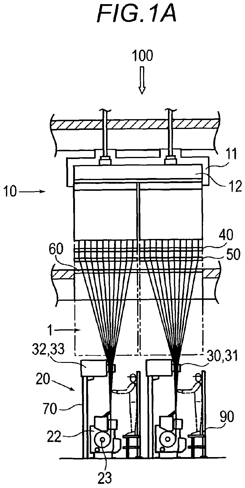
- Figure 1A is a front view of the take-up winding facility 100 according to the first embodiment of the present invention.
- Figure 1B is a side view of the take-up winding facility 100 according to the first embodiment of the present invention.
- Figure 2 is a perspective view of a take-up winding device 20.
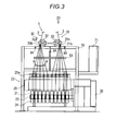
- Figure 3 is a side view of the take-up winding device 20.
- the direction in which gravity acts is defined as the vertical direction.
- the axial direction of a bobbin holder shaft 23 provided in a take-up winding machine 22 described below is defined as a front-back direction.
- a side of the bobbin holder shaft 23 coupled to a driving device 26 is defined as a back side.
- the other side of the bobbin holder shaft 23 is defined as a front side.
- a direction orthogonal to the vertical direction and the front-back direction is defined as a lateral direction.
- the take-up winding facility 100 is composed mainly of a spinning machine 10 spinning a plurality of yarns 1 and a take-up winding device 20 winding the yarns 1 spun out by the spinning machine 10.
- a synthetic filament yarn material from a chip hopper (not shown in the drawings) is introduced into the spinning machine 10.
- the spinning machine 10 then feeds the introduced synthetic filament yarn material to a spin-out section 11 via an extruder (not shown in the drawings) and a prefilter (not shown in the drawings).
- a spinning head 12 included in the spin-out section 11 spins out and feeds a plurality of yarns (filament yarns), 1 to a take-up winding device 20.
- the take-up winding device 20 is composed mainly of the take-up winding machine 22, a first yarn feeding roller 30, and a second yarn feeding roller 31.
- the take-up winding machine 22 winds the yarns 1 spun out by the spinning machine 10, around a plurality of bobbins 21.
- the take-up winding mach i ne 22 includes a bobb i n holder shaft 23 on wh i ch the plurality of bobbins 21 are installed, a contact roller (not shown in the drawings) configured to rotate in contact with packages 24 formed on the respective bobbins 21, a plurality of traverse devices 25, 25, ... configured to traverse the yarns 1 being wound around the respective bobbins 21, and the driving device 26 configured to drive the bobbin holder shaft 23 and the traverse devices 25, 25, ...
- the yarn feeding rollers 30, 31 are arranged above and immediately before the take-up winding machine 22 at a distance from each other in the axial direction of the bobbin holder shaft 23.
- the yarn feeding rollers 30, 31 take off a first yarn group 2 and a second yarn group 3 including the plurality of spun yarns 1 spun out by the spinning head 12 and feed out the taken-off yarn groups 2, 3 to the take-up winding machine 22. That is, each of the yarn feeding rollers 30, 31 provides the function of taking off the yarn groups 2, 3 and the function of feeding out the yarn groups 2, 3.
- the first yarn feeding roller 30 includes a first roller section 30b having a yarn contact portion that comes into contact with the yarn groups 2, 3, and a first roller shaft 30a corresponding to a rotating shaft to which the first roller section 30a is fixed.
- the first yarn feeding roller 30 takes off the first yarn group 2 spun out by the spinning machine 10 and also takes off the second yarn group 3 fed out from the second yarn feeding roller 31 and also feeds out the second yarn groups to the take-up winding machine 22.
- the second yarn feeding 31 includes a second roller section 31b having a yarn contact portion that comes into contact with the yarn groups 2, 3, and a second roller shaft 31a corresponding to a rotating shaft to which the second roller section 31b is fixed.
- the second yarn feeding roller 31 takes off the second yarn group 3 spun out by the spinning machine 10 and also takes off the first yarn group 2 fed out from the first yarn feeding roller 30 and also feeds out the first yarn groups to the take-up winding machine 22.
- the roller shafts 30a, 31b of the yarn feeding rollers 30, 31 are provided so as to extend orthogonally to the bobbin holder shaft 23 of the take-up winding machine 22 and in the horizontal direction. Furthermore, the roller shafts 30a, 31b of the yarn feeding rollers 30, 31 have substantially the same axial length. The yarn feeding rollers 30, 31 are positioned such that the peripheral surfaces thereof lie opposite each other.
- the yarn feeding rollers 30, 31 rotate in the opposite directions.
- the first yarn feeding roller 30 is rotationally driven by a first motor unit 32.
- the first motor unit 32 is fixedly supported on a frame 70.
- the first yarn feeding roller 30 is indirectly supported on the frame 70 by the first motor unit 30.
- the second yarn feeding roller 31 is rotationally driven by a second motor unit 33.
- the second motor unit 33 is fixedly supported on the frame 70.
- the second yarn feeding roller 31 is indirectly supported on the frame 70 by the second motor unit 33.
- the motor units 32, 33 are connected to an inverter 71 and supplied with power by the inverter 71. That is, the inverter 71 is shared by the motor units 32, 33 configured to rotationally drive the yarn feeding rollers 30, 31, respectively.
- the inverter 71 controllably drives the motor units 32, 33 in the same manner so as to allow the yarn feeding rollers 30, 31 to rotate at the same rotation speed.
- the spinning machine 10 is located above the take-up winding device 20.
- the spinning machine 10 includes a spin-out section 11 configured to spin out the plurality of yarns 1.
- the spin-out section 11 includes the spinning head 12 including spinnerets (not shown in the drawings) corresponding to a plurality of holes through which the yarns 1 are spun out.
- the spinning head 12 is located in a direction (the lateral direction of the take-up winding facility 100) orthogonal to the axial direction of the bobbin holder shaft 23 of the take-up winding device 20.
- the spinning head 12 is located such that the spinnerets formed in the bottom surface of the spinning head 12 are arranged substantially linearly in the direction orthogonal to the axial direction of the bobbin holder shaft 23.
- an oiling device 40, a migration nozzle 50, and a shutter 60 are provided below the spinning section 11 included in the spinning machine 10.
- the oiling device 40 supplies lubricant to the yarns 1 in order to reduce the friction between the yarns and a guide and the like, thus preventing possible charging and providing the yarns 1 with flexibility and the like.
- the migration nozzle 50 appropriately disturbs the flow of the yarns 1 in order to uniformly migrate the lubricant applied to the yarns 1 by the oiling device 40.
- the shutter 60 is moved to prevent any broken yarn 1 from falling.
- the shutter 60 may push the broken yarn away to an admission port formed close to the shutter 60 for removal or the opening of the shutter may be adjusted according to a variation in outside air temperature to control the temperature of the spin-out section 11.
- the oiling device 40, the migration nozzle 50, and the shutter 60 are provided below the spinning head 12 included in the spin-out section of the spinning machine 10.
- the vicinity of the take-up winding machine 22 of the take-up winding device 20 can be simplified.
- the arrangement of the oiling device 40, the migration nozzle 50, and the shutter 60 is not limited to this order. For functional reasons, it is only necessary that the migration nozzle 50 is located downstream side of the oiling device 40 in the yarn feeding direction. Furthermore, not all of the oiling device 40, the migration nozzle 50, and the shutter 60 are provided below the spin-out section 11. For example, with only the shutter 60 located below the spin-out section 11, the remaining oiling device 40 and migration nozzle 50 may be arranged immediately before the yarn feeding rollers 30, 31.
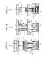
- Figure 4A is a plan view of the yarn feeding rollers 30, 31.
- Figure 4B is a side view of the yarn path of the first yarn group 2 and the yarn feeding rollers 30, 31.
- Figure 4C is a side view of the yarn path of the second yarn group 3 and the yarn feeding rollers 30, 31.
- the plurality of yarns 1 spun out by the spinning head 12 of the spinning machine 10 are divided into the first yarn group 2 and the second yarn group 3 between the spinning machine 10 and the yarn feeding rollers 30, 31.
- the first yarn group 2 and the second yarn group 3 are spun out in a line in the lateral direction.
- the first yarn group 2 is taken off from the spinning machine 10 by the first yarn feeding roller 30.
- the second yarn group 3 is taken off from the spinning machine 10 by the second yarn feeding roller 31. That is, as shown in Figures 1A, 1B , and 2 , after spun out by the spinning head 12, the first yarn group 2 is guided along the rotating direction of the first yarn feeding roller 30, and the second yarn group 3 is guided along the rotation direction of the second yarn feeding roller 31, respectively, with the distances between the yarns 1 gradually reduced.
- the first yarn group 2 to be guided to the first yarn feeding roller 30 is guided to a base end side portion 30c of the first roller section 30b of the first yarn feeding roller 30 (to the first motor unit 32 side of the first roller section 30b) and then to a base end side portion 31c of the second roller section 31b of the second yarn feeding roller 31 (to the second motor unit 33 side of the second roller section 31b).
- the first yarn group 2 travels from the left side, in the figures, of the first yarn feeding roller 30 to the base end side portion 30c of the first yarn feeding roller 30.
- the first yarn group 2 then passes around the lower portion of the first yarn feeding roller 30 along the rotating direction (counterclockwise in the figures) of the first yarn feeding roller 30.
- the first yarn group 2 then approaches the base end side portion 31c of the second yarn feeding roller 31.
- the first yarn group 2 further passes around the upper portion of the second yarn feeding roller 31 along the rotating direction (clockwise in the figures) of the second yarn feeding roller 31.
- the first yarn group 2 is then spread on the right side, in the figures, of the second yarn feeding rotter 31.
- the yarns 1 are guided to the take-up winding machine 22 located below.
- the second yarn group 3 to be guided to the second yarn feeding roller 31 passes through a leading end side portion 31d of the second roller portion 31b of the second yarn feeding roller 31 and a leading end side portion 30d of the first roller section 30b of the first yarn feeding roller 30.
- the second yarn group 3 travels from the right side, in the figures, of the second yarn feeding roller 31 to the leading end side portion 31d of the second yarn feeding roller 31.
- the second yarn group 3 then passes around the lower portion of the second yarn feeding roller 31 along the rotating direction (clockwise in the figures) of the second yarn feeding roller 31.
- the second yarn group 3 then approaches the leading end side portion 30d of the first yarn feeding roller 30.
- the second yarn group 3 further passes around the upper portion of the first yarn feeding roller 30 along the rotating direction (clockwise in the figures) of the first yarn feeding roller 30.
- the second yarn group 3 is then spread on the left side, in the figures, of the first yarn feeding roller 30.
- the yarns 1 are guided to the take-up winding machine 22 located below.
- the first yarn group 2 is taken off and fed out on the base end side portions 30c, 31c of the yarn feeding rollers 30, 31.
- the second yarn group 3 is taken off and fed out on the leading end side portions 30d, 31d of the yarn feeding rollers 30, 31.
- the yarn groups 2, 3 are prevented from interfering with each other on the roller sections 30b, 31b of the yarn feeding rollers 30, 31.
- the yarns 1 fed from the yarn feeding rollers 30, 31 to the take-up winding machine 22 are interlaced before being fed to the take-up winding machine 22.
- An interlace 63 is provided between the first yarn feeding roller 30 and the take-up winding machine 22, and between the second yarn feeding roller 31 and the take-up winding machine 22.
- Interface nozzles (not shown in the drawings) eject air to form a partial interlaced portion on the yarns 1.
- yarns included in the yarns 1 are entangled with one another so as to converge.
- the interlace 63 has only to process the tensed yarns 1. Consequently, the interlace 63 need not be located between the first yarn feeding roller 30 and the take-up winding machine 22, and the second yarn feeding roller 31 and the take-up winding machine 22 but on the yarn paths of the yarns 1 between the yarn feeding rollers 30, 31.
- the yarns 1 having passed through the interlace 63 are fed to the traverse device 25 via a traverse support point guide 25a. Thereafter, the yarns 1 are traversed by the traverse device 25 and then wound around the bobbins 21 installed on the bobbin holder shaft 23.
- Figure 5 is a plan view of yarn feeding rollers 30, 31 in the take-up winding facility 100 according to the second embodiment of the present invention.
- the roller peripheral surface of a first roller section 30b is surface-treated such that the friction coefficient of a yarn contact portion that comes into contact with a first yarn group 2 is relatively different from that of a yarn contact portion that comes into contact with a second yarn group 3.
- first roller section 30b of the first yarn feeding roller 30 mirror finish is applied to a base end side portion 30c of the first roller section 30b corresponding to the yarn contact portion that comes into contact with the first yarn group 2 and to the portion (take-off portion) on which the first yarn group 2 taken off from the spinning machine 10 is placed so that the base end side portion 30c has a large friction coefficient with respect to the yarns 1.
- Satin finish is applied to a leading end side portion 30d of the first roller section 30b corresponding to the yarn contact portion that comes into contact with the second yarn group 3 and to the portion (feed-out portion) from which the second yarn group 3 is fed out so that the leading end side portion 30d has a small friction coefficient with respect to the yarns 1.
- the roller peripheral surface of a second roller section 31b is surface-treated such that the friction coefficient of a yarn contact portion that comes into contact with the first yarn group 2 is relatively different from that of a yarn contact portion that comes into contact with the second yarn group 3.
- mirror finish is applied to a leading end side portion 31d of the second roller section 31b corresponding to the yarn contact portion that comes into contact with the second yarn group 3 and to the portion (take-off portion) on which the second yarn group 3 taken off from the spinning machine 10 is placed so that the leading end side portion 31d has a large friction coefficient with respect to yarns 1.
- Satin finish is applied to a base end side portion 31c of the second roller section 31b corresponding to the yarn contact portion that comes into contact with the first yarn group 2 and to the portion (feed-out portion) from which the first yarn group 2 is fed out so that the base end side portion 31c has a small friction coefficient with respect to the yarns 1.
- the take-off portion is subjected to mirror finish so as to have an increased friction coefficient as described above.
- the roller peripheral surfaces of the roller sections 30b, 31b are treated so as to prevent the yarns 1 from slipping easily over the roller peripheral surfaces. This allows the rotational driving force of the yarn feeding rollers 30, 31 to be reliably transmitted to the yarns 1.
- the feed-out portion is subjected to satin finish so as to have a reduced friction coefficient. This reduces a variation in the tension of the yarns 1 in the take-up winding machine 22.
- the surface treatment of the roller peripheral surfaces of the roller sections 30b, 31b is not limited to mirror finish and satin finish.
- the surface treatment method is not particularly limited provided that the roller peripheral surfaces of the roller sections 30b, 31b are surface-treated as follows: for the first yarn feeding roller 30, the friction coefficient of the roller peripheral surface of the portion that comes into contact with the first yarn group 2 is larger than that of the roller peripheral surface of the portion that comes into contact with the second yarn group 3, and for the second yarn feeding roller 31, the friction coefficient of the roller peripheral surface of the portion that comes into contact with the second yarn group 3 is larger than that of the roller peripheral surface of the portion that comes into contact with the first yarn group 2. Furthermore, the friction coefficient has the opposite relationship depending on the yarn type.
- Figure 6A is a plan view of yarn feeding rollers 30, 31 in the take-up winding facility 100 according to the third embodiment of the present invention.
- Figure 6B is a side view of the yarn path of a first yarn group 2 and the yarn feeding rollers 30, 31 in the take-up winding facility according to the third embodiment of the present invention.
- Figure 6C is a side view of the yarn path of a second yarn group 3 and the yarn feeding rollers 30, 31 in the take-up winding facility 100 according to the third embodiment of the present invention.
- the roller diameter of a yarn contact portion that comes into contact with a first yarn group 2 is relatively different from that of a yarn contact portion that comes into contact with a second yarn group 3.
- the roller diameter of a leading end side portion 30d of the first yarn feeding roller 30 is larger than that of a base end side portion 30c of the first yarn feeding roller 30: the leading end side portion 30d corresponds to the yarn contact portion that comes into contact with the second yarn group 3 and to a portion (feed-out portion) from which the second yarn group 3 is fed out to a take-up winding machine 22, and the base end side portion 30c corresponds to the yarn contact portion that comes into contact with the first yarn group 2 and to a portion (take-off portion) on which the first yarn group 2 taken off from a spinning machine 10 is placed.
- the roller diameter of a yarn contact portion that comes into contact with the first yarn group 2 is different from that of a yarn contact portion that comes into contact with a second yarn group 3.
- the roller diameter of a base end side portion 31c of the second yarn feeding roller 31 is larger than that of a leading end side portion 31d of the second yarn feeding roller 31: the base end side portion 31c corresponds to the yarn contact portion that comes into contact with the first yarn group 2 and to a portion (feed-out portion) from which the first yarn group 2 is fed out to the take-up winding machine 22, and the leading end side portion 31d corresponds to the yarn contact portion that comes into contact with the second yarn group 3 and to a portion (take-off portion) on which the second yarn group 3 taken off from the spinning machine 10 is placed.
- the roller diameter of the feed-out portion is set to be larger than that of the take-off portion as described above. This makes the peripheral speed of the yarn feeding rollers 30, 31 at the yarn group 2, 3 feed-out portion higher than that of the yarn feeding rollers 30, 31 at the yarn group 2, 3 take-off portion.
- the yarn feeding rollers 30, 31 in the take-up winding facility 100 according to the fourth embodiment may be processed as follows. As is the case with the yarn feeding rollers 30, 31 in the take-up winding facility according to the third embodiment, the yarn group 2, 3 take-off portion of the roller peripheral surface of each of the roller sections 30b, 31b is subjected to mirror finish, whereas the yarn group 2, 3 feed-out portion of the roller peripheral surface of each of the roller sections 30b, 31b is subjected to satin finish. Furthermore, the roller diameter of the portion subjected to satin finish is set to be larger than that of the portion subjected to mirror finish.
- Figure 7A is a front view of the take-up winding facility 100 according to the first embodiment of the present invention (the take-up winding facility 100 in which the spinning head 12 is located in the direction orthogonal to the axial direction of the bobbin holder shaft 23).
- Figure 7B is a front view of the take-up winding facility 100 according to the fourth embodiment of the present invention.
- Figure 7C is a side view of the take-up winding facility 100 according to the fourth embodiment of the present invention.
- Figure 8 is a side view of yarn feeding rollers 30, 31 in the take-up winding facility 100 according to the fourth embodiment of the present invention.
- a spinning head 12 included in a spin-out section 11 of a spinning machine 10 is located along the axial direction (the front-back direction of the take-up winding facility 100) of a bobbin holder shaft 23 provided in a take-up winding machine 22 in a take-up winding device 20.
- the spinning head 12 is located such that spinnerets formed in the bottom surface of the spinning head 12 are arranged substantially linearly in the axial direction of the bobbin holder shaft 23.
- the yarn group 2, 3 when being fed from the spinning head 12 to each of the yarn feeding rollers 30,31, the yarn group 2, 3 approaches the yarn feeding roller 30, 31 at an approach angle B to the yarn feeding roller 30, 31.
- the approach angle B refers to the angle between the yarn path from the spinning head 12 to each of the yarn feeding rollers 30, 31 and the horizontal direction.
- the approach angle B is larger than that obtained in the case where the spinning head 12 is located in the direction orthogonal to the axial direction of the bobbin holder shaft 23 ( Figure 7A ).
- tension applied to the yarn group 2, 3 approaching the yarn feeding roller 30, 31 is optimized. Consequently, the quality of yarns 1 can be maintained at the same level.
- the spinning machine 10 can be placed, with respect to a take-up winding device 20, at a lower position than in the case where the spinning head 12 is located in the direction orthogonal to the axial direction of the bobbin holder shaft 23 ( Figure 7A ). Additionally, the yarns 1 spun out by the spinning head 12 can be fed to the yarn feeding rollers 30, 31 so as to be evenly distributed between the yarn feeding rollers 30, 31.
- Figure 9 is a side view of a take-up winding facility 100 according to a fifth embodiment of the present invention.
- At least two, plural yarn feeding rollers are arranged above and immediately before a take-up winding machine 22 at intervals along the axial direction of a bobbin holder shaft 23.
- four yarn feeding rollers, a first yarn feeding roller 30, a second yarn feeding roller 31, a third yarn feeding roller 35, and a fourth yarn feeding roller 36 are arranged above and immediately before the take-up winding machine 22 at intervals along the axial direction of the bobbin holder shaft 23.
- the yarn feeding rollers provided in the take-up winding facility 100 according to the fifth embodiment are arranged such that the first yarn feeding roller 30 is located on the front side of the bobbin holder shaft 23 (the leading end side of the bobbin holder shaft 23) and followed by the second yarn feeding roller 31, third yarn feeding roller 35, and fourth yarn feeding roller 36 arranged in this order at intervals.
- the yarn feeding rollers 30, 31, 35, 36 form yarn feeding roller groups each composed of every two yarn feeding rollers starting with the first yarn feeding roller 30 located on the front side of the bobbin holder shaft 23 (the leading end side of the bobbin holder shaft 23).
- the first yarn feeding roller 30 and the second yarn feeding roller 31, located opposite the first yarn feeding roller 30, form a first yarn feeding roller group 37.
- a plurality of yarns 1 spun out by a spinning head 12 are divided into four equal groups between a spinning machine 10 and the yarn feeding rollers 30, 31, 35, 36.
- a first yarn group 2 a second yarn group 3, a third yarn group 4, and a fourth yarn group 5 are formed.
- the yarn groups 2, 3, 4, 5 are further divided into two sets of yarn groups, that is, a set of the yarn groups 2, 3 and a set of the yarn groups 4, 5. Then, the set of the yarn groups 2, 3 is supplied to the first yarn feeding roller group 37. The set of the yarn groups 4, 5 is supplied to the second yarn feeding roller group 38.
- the first yarn group 2 is taken off from the spinning machine 10 by the first yarn feeding roller 30.
- the second yarn group 3 is taken off from the spinning machine 10 by the second yarn feeding roller 31.
- the third yarn group 4 is taken off from the spinning machine 10 by the third yarn feeding roller 35.
- the fourth yarn group 5 is taken off from the spinning machine 10 by the fourth yarn feeding roller 36.
- the yarn groups 2, 3, 4, 5 are divided into the yarn feeding roller groups 37, 38, which are then taken off from the spinning machine 10 by the corresponding yarn feeding rollers.
- the subsequent yarn paths in the first yarn feeding roller group 37 and the second yarn feeding roller group 38 are similar to those in the take-up winding facilities 100 according to the first to fourth embodiments, that is, those obtained when only the first yarn feeding roller 30 and the second yarn feeding roller 31 are provided.
- the yarn groups 2, 3, 4, 5 taken off by the yarn feeding rollers are spread, on the yarn feeding rollers 30, 31, 35, 36, into the yarns 1 in the front-back direction of the take-up winding facility 100.
- the spread yarns 1 are then supplied to the take-up winding machine 22.
- the spread angle of the yarn 1 is at most a predetermined angle (for example, at most 20 degrees) to the vertical line so as to maintain the same level of yarn quality.
- an operator stands on a working step 90.
- the operator allows a suction device to suck and hold the first yarn group 2 spun out by the spinning head 12.
- the operator then operates the suction device to hook the first yarn group 2 on the first yarn feeding roller 30.
- the operator passes the first yarn group 2 onto the second yarn feeding roller 31 so that the first yarn group 2 extends in S form.
- the operator places the first yarn group 2 onto a yarn hooking assisting guide 64 provided on the frame 70 located behind the second yarn feeding roller 31.
- the operator allows the second yarn group 3 spun out by the spinning head 12 to be sucked and held and then passed from the second yarn feeding roller 31 to the first yarn feeding roller 30 so that the second yarn group 3 extends in S form.
- the operator then allows the second yarn group 3 to be placed on a yarn hooking assisting guide 64 positioned in front of the first yarn feeding roller 30.
- the operator guides the yarns 1 in the first yarn group 2, via the interlace 63, to the traverse support point guide 25a included in the traverse device 25.
- the operator guides the yarns 1 in the second yarn group 3, via the interlace 63, to the traverse support point guide 25a included in the traverse device 25.
- the yarn hooking assisting guide 64 is provided such that with the first yarn group 2 or the second yarn group 3 temporarily hooked on the yarn hooking assisting guide 64, the yarns 1 are fed out from the yarn feeding rollers 30, 31 as in the case of the present embodiment. In this case, the yarn hooking operation can be easily achieved.
- Whether the yarn hooking assisting guide 64 is positioned close to each of the yarn feeding rollers 30, 31 or midway between the yarn feeding rollers 30, 31 is determined according to the shape of the suction device and the like.
- the specific position of the yarn hooking assisting guide 64 is not limited. While the present invention has been described with respect to preferred embodiments thereof, it will be apparent to those skilled in the art that the disclosed invention may be modified in numerous ways and may assume many embodiments other than those specifically set out and described above. Accordingly, it is intended by the appended claims to cover all modifications of the present invention that fall within the scope of the invention.
Landscapes
- Chemical & Material Sciences (AREA)
- Oil, Petroleum & Natural Gas (AREA)
- Spinning Methods And Devices For Manufacturing Artificial Fibers (AREA)
- Winding Filamentary Materials (AREA)
Abstract
Description
- The present invention relates to a take-up winding facility in which a winding machine winds a plurality of filament yarns(hereinafter simply referred to as yarns) spun out by a spinning machine, via a plurality of rollers.
- In a conventional take-up winding facility, one yarn feeding roller is located immediately before each take-up winding machine so that all of a plurality of spun-out yarns are spread by the yarn feeding roller located immediately before the take-up winding machine and are then wound around a plurality of bobbins installed in the take-up winding machine (see the Unexamined Japanese Patent Application Publication (Tokkai) No.
2003-285972 - In the take-up winding facility disclosed in the Unexamined Japanese Patent Application Publication (Tokkai) No.
2003-285972 - In another example of a conventional take-up winding facility, a plurality of yarn feeding rollers arranged immediately before a take-up winding machine are provided for each take-up winding machine. A plurality of yarns spun out by the spinning machine are distributively guided from the yarn feeding rollers to bobbins installed in the take-up winding machine and the number of which is the same as that of the plurality of yarns, and are then wound around the bobbins (see PCT National Publication No.
2005-534825 - However, in the take-up winding facility disclosed in the Unexamined Japanese Patent Application Publication (Tokkai) No.
2003-285972 2003-285972 - On the other hand, in the take-up winding facility disclosed in PCT National Publication No.
2005-534825 - The present invention has been developed in order to solve the above-described problems. An object of the present invention is to provide a take-up winding facility which is miniaturized by reducing the take-up winding device height and which is simplified by simplifying the layout of vicinity of the take-up winding machine.
- The problems to be solved by the present invention have been described. Now, means for solving the problems will be described.
- A first invention provides a take-up winding facility configured to feed a plurality of yarns spun out by a spinning machine, from above to below to simultaneously wind the plurality of yarns around respective plural bobbins installed on a bobbin holder shaft in one take-up winding machine,
wherein a plurality of yarn feeding rollers are arranged immediately before the take-up winding machine, and
the plurality of yarns spun out by the spinning machine are divided into a plurality of groups which are then fed to the respective plural yarn feeding rollers arranged immediately before the take-up winding machine, and the groups of yarns are distributively wound around respective bobbins via the plurality of yarn feeding rollers. - A second invention corresponds to the take-up winding facility according to the first invention, wherein the plurality of yarn feeding rollers arranged immediately before the take-up winding machine include at least a first yarn feeding roller and a second yarn feeding roller arranged at a distance from each other in an axial direction of the bobbin holder shaft to feed out a first yarn group and a second yarn group including all or a part of the plurality of yarns, to the take-up winding machine,
the first yarn feeding roller rotates so as to take off the first yarn group from the spinning machine to feed out the first yarn group to the second yarn feeding roller and to take off the second yarn group fed out from the second yarn feeding roller to feed out the second yarn group to the take-up winding machine,
the second yarn feeding roller rotates so as to take off the second yarn group from the spinning machine to feed out the second yarn group to the first yarn feeding roller and to take off the first yarn group fed out from the first yarn feeding roller to feed out the first yarn group to the take-up winding machine, and the take-up winding machine winds the second yarn group spreadingly fed out from the first yarn feeding roller and the first yarn group spreadingly fed out from the second yarn feeding roller, around the bobbins. - A third invention corresponds to the take-up winding facility according to the second invention, wherein the first yarn feeding roller and the second yarn feeding roller rotate in opposite directions,
the first yarn feeding roller rotates so as to feed out the first yarn group taken off from the spinning machine, to the second yarn feeding roller while allowing the first yarn group to be guided around a lower portion of the first yarn feeding roller and to feed out the second yarn group taken off from the second yarn feeding roller, to the take-up winding machine while allowing the second yarn group to be guided around an upper portion of the first yarn feeding roller, and the second yarn feeding roller rotates so as to feed out the second yarn group taken off from the spinning machine, to the first yarn feeding roller while allowing the second yarn group to be guided around a lower portion of the second yarn feeding roller and to feed out the first yarn group taken off from the first yarn feeding roller, to the take-up winding machine while allowing the first yarn group to be guided around an upper portion of the second yarn feeding roller. - A fourth invention corresponds to the take-up winding facility according to the second or third invention, wherein in each of the first yarn feeding roller and the second yarn feeding roller, a friction coefficient of a yarn contact portion that comes into contact with the first yarn group is relatively different from a friction coefficient of a yarn contact portion that comes into contact with the second yarn group.
- A fifth invention corresponds to the take-up winding facility according to any one of the second to fourth inventions, wherein in each of the first yarn feeding roller and the second yarn feeding roller, a roller diameter of the yarn contact portion that comes into contact with the first yarn group is relatively different from a roller diameter of the yarn contact portion that comes into contact with the second yarn group.
- A sixth invention corresponds to the take-up winding facility according to any one of the second to fifth inventions,
Claims 2 to 5, further including a yarn hooking assisting guide configured to temporarily hold the first yarn group or the second yarn group when the first yarn group or the second yarn group is hooked on the first yarn feeding roller and the second yarn feeding roller. - A seventh invention corresponds to the take-up winding facility according to any one of the second to sixth inventions, further including an interlace provided between the first yarn feeding roller and the second yarn feeding roller or between the first yarn feeding roller and the take-up winding machine, and between the second yarn feeding roller and the take-up winding machine to form a interlaced portion on the yarns.
- An eighth invention corresponds to the take-up winding facility according to any one of the second to seventh inventions, further including an oiling device provided below a spin-out section of the spinning machine to apply lubricant to the yarns.
- A ninth invention corresponds to the take-up winding facility according to the eighth invention, further including a migration nozzle provided downstream side of the oiling device in a yarn feeding direction to eject gas onto the yarns.
- A tenth invention corresponds to the take-up winding facility according to any one of the second to ninth inventions, further including a shutter provided below the spin-out section of the spinning machine to prevent a broken yarn from falling.
- An eleventh invention corresponds to the take-up winding facility according to any one of the second to tenth inventions, wherein a common inverter is used to drive the first yarn feeding roller and the second yarn feeding roller.
- A twelfth invention corresponds to the take-up winding facility according to any one of the second to eleventh inventions, wherein the spinning machine includes the spin-out section located along the axial direction of the bobbin holder shaft, and
the first yarn feeing roller and the second yarn feeding roller feed out the first yarn group and second yarn group including all or a part of the plurality of yarns spun out by the spin-out section, to the take-up winding machine. - The present invention exerts the following effects.
- In the first invention, the operation of spreading the yarns is shared by the plurality of yarn feeding rollers arranged immediately before the take-up winding machine. This reduces the number of yarns to be spread by one yarn feeding roller and thus the distance over which the yarns are spread by one yarn feeding roller. As a result, the spread angle of the yarns can be set to at most a predetermined value even with an increase in the number of bobbins installed in one take-up winding machine. Thus, a variation in yarn quality among the plurality of bobbins can be reduced to ensure yarn quality. The first invention also eliminates the need to increase the distance from the take-up winding machine to the yarn feeding roller located immediately before the take-up winding machine. Thus, the take-up winding device height decreases, resulting in a smaller take-up winding facility. This serves to reduce the costs of a building in which the take-up winding facility is installed, improve the operability of yarn hooking and the like, and reduce costs for air conditioning in the building in which the take-up winding facility is installed.
- In the second invention, each of the yarn feeding rollers provides both the function of taking off the yarns spun out by the spinning machine and the function of feeding out the yarns to the take-up winding machine. This eliminates the need to provide a separate yarn feeding roller configured to take off the yarns spun out by the spinning machine, between the spinning machine and the yarn feeding roller located immediately before the take-up winding machine. This in turn prevents the yarn feeding rollers from being densely arranged close to the take-up winding machine, thus allowing the take-up winding facility to be simplified.
- In the third invention, each of the yarn feeding rollers can reliably take off the yarns spun out by the spinning machine. The yarn feeding roller can also take off the yarns fed out from the other yarn feeding rollers to reliably feed out the yarns to the take-up winding machine.
- In the fourth invention, in each of the yarn feeding rollers, the friction coefficient of the yarn contact portion corresponding to a yarn group take-off portion is different from that of the yarn contact portion corresponding to a yarn group feed-out portion. Thus, tension applied to the yarns is optimized, ensuring appropriate yarn quality and enabling stable yarn winding.
- In the fifth invention, in each of the yarn feeding rollers, the roller diameter of the yarn group take-off portion is different from that of the yarn group feed-out portion. Thus, the tension applied to the yarns is optimized, ensuring the appropriate yarn quality and enabling stable yarn winding.
- In the sixth invention, the yarns can be temporarily held before being hooked on each of the yarn feeding rollers. Thus, a yarn hooking operation is facilitated.
- In the seventh invention, the interlace located between the yarn feeding rollers, or between each of the yarn feeding rollers and the take-up winding machine allows the yarn path to be fixed. This enables stable yarn winding.
- In the eighth invention, the oiling device can be installed away from the take-up winding machine. Thus, the layout of vicinity of the take-up winding machine can be simplified.
- In the ninth invention, the migration nozzle can be installed away from the take-up winding machine. Thus, the layout of vicinity of the take-up winding machine can be simplified.
- In the tenth invention, the shutter can be installed away from the take-up winding machine. Thus, the layout of vicinity of the take-up winding machine can be simplified.
- In the eleventh invention, the yarn feeding rollers can be easily controlled. This enables a reduction in the number of components required and thus in costs.
- In the twelfth invention, the spinning machine can be located below the yarn feeding rollers with the same level of yarn quality maintained. Furthermore, the plurality of yarns spun out by the spinning machine can be fed to the yarn feeding rollers so as to be evenly distributed between the yarn feeding rollers.
Other features, elements, processes, steps, characteristics and advantages of the present invention will become more apparent from the following detailed description of preferred embodiments of the present invention with reference to the attached drawings. -
-
Figure 1A is a front view of a take-up windingfacility 100 according to a first embodiment of the present invention, andFigure 1B is a side view of the take-up windingfacility 100 according to the first embodiment of the present invention. -
Figure 2 is a perspective view of a take-up windingdevice 20. -
Figure 3 is a side view of the take-up windingdevice 20. -
Figure 4A is a plan view ofyarn feeding rollers Figure 4B is a side view of the yarn path of afirst yarn group 2 and theyarn feeding rollers Figure 4C is a side view of the yarn path of asecond yarn group 3 and theyarn feeding rollers -
Figure 5 is a plan view ofyarn feeding rollers facility 100 according to a second embodiment of the present invention. -
Figure 6A is a plan view ofyarn feeding rollers facility 100 according to a third embodiment of the present invention,Figure 6B is a side view of theyarn feeding rollers facility 100 according to the third embodiment of the present invention, andFigure 6C is a side view of the yarn path of asecond yarn group 3 and theyarn feeding rollers facility 100 according to the third embodiment of the present invention. -
Figure 7A is a front view of the take-up windingfacility 100 according to the first embodiment of the present invention,Figure 7B is a front view of a take-up windingfacility 100 according to a fourth embodiment of the present invention, andFigure 7C is a side view of the take-up windingfacility 100 according to the fourth embodiment of the present invention. -
Figure 8 is a side view ofyarn feeding rollers facility 100 according to the fourth embodiment of the present invention. -
Figure 9 is a side view of a take-up windingfacility 100 according to a fifth embodiment of the present invention. - First, the general configuration of a take-up winding
facility 100 according to a first embodiment of the present invention will be described with reference to the drawings.Figure 1A is a front view of the take-up windingfacility 100 according to the first embodiment of the present invention.Figure 1B is a side view of the take-up windingfacility 100 according to the first embodiment of the present invention.Figure 2 is a perspective view of a take-up windingdevice 20.Figure 3 is a side view of the take-up windingdevice 20. In the description below, the direction in which gravity acts is defined as the vertical direction. The axial direction of abobbin holder shaft 23 provided in a take-up windingmachine 22 described below is defined as a front-back direction. A side of thebobbin holder shaft 23 coupled to adriving device 26 is defined as a back side. The other side of thebobbin holder shaft 23 is defined as a front side. Furthermore, when the take-up windingmachine 22 is viewed from the front thereof, a direction orthogonal to the vertical direction and the front-back direction is defined as a lateral direction. - As shown in
Figures 1A and 1B , the take-up windingfacility 100 is composed mainly of a spinningmachine 10 spinning a plurality ofyarns 1 and a take-up windingdevice 20 winding theyarns 1 spun out by the spinningmachine 10. - A synthetic filament yarn material from a chip hopper (not shown in the drawings) is introduced into the spinning
machine 10. The spinningmachine 10 then feeds the introduced synthetic filament yarn material to a spin-outsection 11 via an extruder (not shown in the drawings) and a prefilter (not shown in the drawings). A spinninghead 12 included in the spin-outsection 11 spins out and feeds a plurality of yarns (filament yarns), 1 to a take-up windingdevice 20. - As shown in
Figures 2 and3 , the take-up windingdevice 20 is composed mainly of the take-up windingmachine 22, a firstyarn feeding roller 30, and a secondyarn feeding roller 31. - As shown in
Figures 2 and3 , the take-up windingmachine 22 winds theyarns 1 spun out by the spinningmachine 10, around a plurality ofbobbins 21. The take-up winding mach ine 22 includes a bobb i nholder shaft 23 on wh i ch the plurality ofbobbins 21 are installed, a contact roller (not shown in the drawings) configured to rotate in contact withpackages 24 formed on therespective bobbins 21, a plurality oftraverse devices yarns 1 being wound around therespective bobbins 21, and the drivingdevice 26 configured to drive thebobbin holder shaft 23 and thetraverse devices - As shown in
Figures 1A, 1B ,2 , and3 , theyarn feeding rollers machine 22 at a distance from each other in the axial direction of thebobbin holder shaft 23. Theyarn feeding rollers first yarn group 2 and asecond yarn group 3 including the plurality of spunyarns 1 spun out by the spinninghead 12 and feed out the taken-offyarn groups machine 22. That is, each of theyarn feeding rollers yarn groups yarn groups - Specifically, the first
yarn feeding roller 30 includes afirst roller section 30b having a yarn contact portion that comes into contact with theyarn groups first roller shaft 30a corresponding to a rotating shaft to which thefirst roller section 30a is fixed. The firstyarn feeding roller 30 takes off thefirst yarn group 2 spun out by the spinningmachine 10 and also takes off thesecond yarn group 3 fed out from the secondyarn feeding roller 31 and also feeds out the second yarn groups to the take-up windingmachine 22. - On the other hand, the second yarn feeding 31 includes a
second roller section 31b having a yarn contact portion that comes into contact with theyarn groups second roller shaft 31a corresponding to a rotating shaft to which thesecond roller section 31b is fixed. The secondyarn feeding roller 31 takes off thesecond yarn group 3 spun out by the spinningmachine 10 and also takes off thefirst yarn group 2 fed out from the firstyarn feeding roller 30 and also feeds out the first yarn groups to the take-up windingmachine 22. - The
roller shafts yarn feeding rollers bobbin holder shaft 23 of the take-up windingmachine 22 and in the horizontal direction. Furthermore, theroller shafts yarn feeding rollers yarn feeding rollers - Furthermore, the
yarn feeding rollers yarn feeding roller 30 is rotationally driven by afirst motor unit 32. Thefirst motor unit 32 is fixedly supported on aframe 70. Thus, the firstyarn feeding roller 30 is indirectly supported on theframe 70 by thefirst motor unit 30. On the other hand, the secondyarn feeding roller 31 is rotationally driven by asecond motor unit 33. Thesecond motor unit 33 is fixedly supported on theframe 70. Thus, the secondyarn feeding roller 31 is indirectly supported on theframe 70 by thesecond motor unit 33. - The
motor units inverter 71 and supplied with power by theinverter 71. That is, theinverter 71 is shared by themotor units yarn feeding rollers inverter 71 controllably drives themotor units yarn feeding rollers - As shown in
Figures 1A and 1B , the spinningmachine 10 is located above the take-up windingdevice 20. The spinningmachine 10 includes a spin-outsection 11 configured to spin out the plurality ofyarns 1. The spin-outsection 11 includes the spinninghead 12 including spinnerets (not shown in the drawings) corresponding to a plurality of holes through which theyarns 1 are spun out. The spinninghead 12 is located in a direction (the lateral direction of the take-up winding facility 100) orthogonal to the axial direction of thebobbin holder shaft 23 of the take-up windingdevice 20. Specifically, the spinninghead 12 is located such that the spinnerets formed in the bottom surface of the spinninghead 12 are arranged substantially linearly in the direction orthogonal to the axial direction of thebobbin holder shaft 23. - Furthermore, as shown in
Figures 1A and 1B , anoiling device 40, amigration nozzle 50, and ashutter 60 are provided below thespinning section 11 included in the spinningmachine 10. - The oiling
device 40 supplies lubricant to theyarns 1 in order to reduce the friction between the yarns and a guide and the like, thus preventing possible charging and providing theyarns 1 with flexibility and the like. - The
migration nozzle 50 appropriately disturbs the flow of theyarns 1 in order to uniformly migrate the lubricant applied to theyarns 1 by the oilingdevice 40. - The
shutter 60 is moved to prevent anybroken yarn 1 from falling. Theshutter 60 may push the broken yarn away to an admission port formed close to theshutter 60 for removal or the opening of the shutter may be adjusted according to a variation in outside air temperature to control the temperature of the spin-outsection 11. - In this manner, the oiling
device 40, themigration nozzle 50, and theshutter 60 are provided below the spinninghead 12 included in the spin-out section of the spinningmachine 10. Thus, the vicinity of the take-up windingmachine 22 of the take-up windingdevice 20 can be simplified. - The arrangement of the
oiling device 40, themigration nozzle 50, and theshutter 60 is not limited to this order. For functional reasons, it is only necessary that themigration nozzle 50 is located downstream side of theoiling device 40 in the yarn feeding direction. Furthermore, not all of theoiling device 40, themigration nozzle 50, and theshutter 60 are provided below the spin-outsection 11. For example, with only theshutter 60 located below the spin-outsection 11, the remainingoiling device 40 andmigration nozzle 50 may be arranged immediately before theyarn feeding rollers - Now, the yarn paths of the
yarn groups machine 10 by theyarn feeding rollers machine 22 will be described.Figure 4A is a plan view of theyarn feeding rollers Figure 4B is a side view of the yarn path of thefirst yarn group 2 and theyarn feeding rollers Figure 4C is a side view of the yarn path of thesecond yarn group 3 and theyarn feeding rollers - The plurality of
yarns 1 spun out by the spinninghead 12 of the spinningmachine 10 are divided into thefirst yarn group 2 and thesecond yarn group 3 between the spinningmachine 10 and theyarn feeding rollers first yarn group 2 and thesecond yarn group 3 are spun out in a line in the lateral direction. Thefirst yarn group 2 is taken off from the spinningmachine 10 by the firstyarn feeding roller 30. Thesecond yarn group 3 is taken off from the spinningmachine 10 by the secondyarn feeding roller 31. That is, as shown inFigures 1A, 1B , and2 , after spun out by the spinninghead 12, thefirst yarn group 2 is guided along the rotating direction of the firstyarn feeding roller 30, and thesecond yarn group 3 is guided along the rotation direction of the secondyarn feeding roller 31, respectively, with the distances between theyarns 1 gradually reduced. - As shown in
Figures 4A and 4B , thefirst yarn group 2 to be guided to the firstyarn feeding roller 30 is guided to a baseend side portion 30c of thefirst roller section 30b of the first yarn feeding roller 30 (to thefirst motor unit 32 side of thefirst roller section 30b) and then to a baseend side portion 31c of thesecond roller section 31b of the second yarn feeding roller 31 (to thesecond motor unit 33 side of thesecond roller section 31b). - Specifically, the
first yarn group 2 travels from the left side, in the figures, of the firstyarn feeding roller 30 to the baseend side portion 30c of the firstyarn feeding roller 30. Thefirst yarn group 2 then passes around the lower portion of the firstyarn feeding roller 30 along the rotating direction (counterclockwise in the figures) of the firstyarn feeding roller 30. Thefirst yarn group 2 then approaches the baseend side portion 31c of the secondyarn feeding roller 31. Thefirst yarn group 2 further passes around the upper portion of the secondyarn feeding roller 31 along the rotating direction (clockwise in the figures) of the secondyarn feeding roller 31. Thefirst yarn group 2 is then spread on the right side, in the figures, of the secondyarn feeding rotter 31. Theyarns 1 are guided to the take-up windingmachine 22 located below. - On the other hand, as shown in
Figures 4A and 4C , thesecond yarn group 3 to be guided to the secondyarn feeding roller 31 passes through a leadingend side portion 31d of thesecond roller portion 31b of the secondyarn feeding roller 31 and a leadingend side portion 30d of thefirst roller section 30b of the firstyarn feeding roller 30. - Specifically, the
second yarn group 3 travels from the right side, in the figures, of the secondyarn feeding roller 31 to the leadingend side portion 31d of the secondyarn feeding roller 31. Thesecond yarn group 3 then passes around the lower portion of the secondyarn feeding roller 31 along the rotating direction (clockwise in the figures) of the secondyarn feeding roller 31. Thesecond yarn group 3 then approaches the leadingend side portion 30d of the firstyarn feeding roller 30. Thesecond yarn group 3 further passes around the upper portion of the firstyarn feeding roller 30 along the rotating direction (clockwise in the figures) of the firstyarn feeding roller 30. Thesecond yarn group 3 is then spread on the left side, in the figures, of the firstyarn feeding roller 30. Theyarns 1 are guided to the take-up windingmachine 22 located below. - As described above, the
first yarn group 2 is taken off and fed out on the baseend side portions yarn feeding rollers second yarn group 3 is taken off and fed out on the leadingend side portions yarn feeding rollers yarn groups roller sections yarn feeding rollers - The
yarns 1 fed from theyarn feeding rollers machine 22 are interlaced before being fed to the take-up windingmachine 22. Aninterlace 63 is provided between the firstyarn feeding roller 30 and the take-up windingmachine 22, and between the secondyarn feeding roller 31 and the take-up windingmachine 22. Interface nozzles (not shown in the drawings) eject air to form a partial interlaced portion on theyarns 1. Thus, yarns included in theyarns 1 are entangled with one another so as to converge. Theinterlace 63 has only to process the tensedyarns 1. Consequently, theinterlace 63 need not be located between the firstyarn feeding roller 30 and the take-up windingmachine 22, and the secondyarn feeding roller 31 and the take-up windingmachine 22 but on the yarn paths of theyarns 1 between theyarn feeding rollers - As shown in
Figures 2 and3 , theyarns 1 having passed through theinterlace 63 are fed to thetraverse device 25 via a traversesupport point guide 25a. Thereafter, theyarns 1 are traversed by thetraverse device 25 and then wound around thebobbins 21 installed on thebobbin holder shaft 23. - Now, a take-up winding
facility 100 according to a second embodiment of the present invention will be described below. In the description below, the same arrangements as those of the take-up windingfacility 100 according to the first embodiment are denoted by the same reference numerals and will not be described.Figure 5 is a plan view ofyarn feeding rollers facility 100 according to the second embodiment of the present invention. - As shown in
Figure 5 , in the firstyarn feeding roller 30, the roller peripheral surface of afirst roller section 30b is surface-treated such that the friction coefficient of a yarn contact portion that comes into contact with afirst yarn group 2 is relatively different from that of a yarn contact portion that comes into contact with asecond yarn group 3. - Specifically, on the roller peripheral surface of a
first roller section 30b of the firstyarn feeding roller 30, mirror finish is applied to a baseend side portion 30c of thefirst roller section 30b corresponding to the yarn contact portion that comes into contact with thefirst yarn group 2 and to the portion (take-off portion) on which thefirst yarn group 2 taken off from the spinningmachine 10 is placed so that the baseend side portion 30c has a large friction coefficient with respect to theyarns 1. Satin finish is applied to a leadingend side portion 30d of thefirst roller section 30b corresponding to the yarn contact portion that comes into contact with thesecond yarn group 3 and to the portion (feed-out portion) from which thesecond yarn group 3 is fed out so that the leadingend side portion 30d has a small friction coefficient with respect to theyarns 1. - Similarly, as shown in
Figure 5 , in the secondyarn feeding roller 30, the roller peripheral surface of asecond roller section 31b is surface-treated such that the friction coefficient of a yarn contact portion that comes into contact with thefirst yarn group 2 is relatively different from that of a yarn contact portion that comes into contact with thesecond yarn group 3. - Specifically, on the roller peripheral surface of the
second roller section 31b of the secondyarn feeding roller 31, mirror finish is applied to a leadingend side portion 31d of thesecond roller section 31b corresponding to the yarn contact portion that comes into contact with thesecond yarn group 3 and to the portion (take-off portion) on which thesecond yarn group 3 taken off from the spinningmachine 10 is placed so that the leadingend side portion 31d has a large friction coefficient with respect toyarns 1. Satin finish is applied to a baseend side portion 31c of thesecond roller section 31b corresponding to the yarn contact portion that comes into contact with thefirst yarn group 2 and to the portion (feed-out portion) from which thefirst yarn group 2 is fed out so that the baseend side portion 31c has a small friction coefficient with respect to theyarns 1. - The take-off portion is subjected to mirror finish so as to have an increased friction coefficient as described above. Thus, the roller peripheral surfaces of the
roller sections yarns 1 from slipping easily over the roller peripheral surfaces. This allows the rotational driving force of theyarn feeding rollers yarns 1. Furthermore, the feed-out portion is subjected to satin finish so as to have a reduced friction coefficient. This reduces a variation in the tension of theyarns 1 in the take-up windingmachine 22. - The surface treatment of the roller peripheral surfaces of the
roller sections roller sections yarn feeding roller 30, the friction coefficient of the roller peripheral surface of the portion that comes into contact with thefirst yarn group 2 is larger than that of the roller peripheral surface of the portion that comes into contact with thesecond yarn group 3, and for the secondyarn feeding roller 31, the friction coefficient of the roller peripheral surface of the portion that comes into contact with thesecond yarn group 3 is larger than that of the roller peripheral surface of the portion that comes into contact with thefirst yarn group 2. Furthermore, the friction coefficient has the opposite relationship depending on the yarn type. - Now, a take-up winding
facility 100 according to a third embodiment of the present invention will be described below. In the description below, the same arrangements as those of the take-up windingfacilities 100 according to the first and second embodiments are denoted by the same reference numerals and will not be described.Figure 6A is a plan view ofyarn feeding rollers facility 100 according to the third embodiment of the present invention.Figure 6B is a side view of the yarn path of afirst yarn group 2 and theyarn feeding rollers Figure 6C is a side view of the yarn path of asecond yarn group 3 and theyarn feeding rollers facility 100 according to the third embodiment of the present invention. - As shown in
Figures 6A and 6B , in the firstyarn feeding roller 30, the roller diameter of a yarn contact portion that comes into contact with afirst yarn group 2 is relatively different from that of a yarn contact portion that comes into contact with asecond yarn group 3. Specifically, the roller diameter of a leadingend side portion 30d of the firstyarn feeding roller 30 is larger than that of a baseend side portion 30c of the first yarn feeding roller 30: the leadingend side portion 30d corresponds to the yarn contact portion that comes into contact with thesecond yarn group 3 and to a portion (feed-out portion) from which thesecond yarn group 3 is fed out to a take-up windingmachine 22, and the baseend side portion 30c corresponds to the yarn contact portion that comes into contact with thefirst yarn group 2 and to a portion (take-off portion) on which thefirst yarn group 2 taken off from a spinningmachine 10 is placed. - Similarly, as shown in
Figures 6A and 6C , in the secondyarn feeding roller 31, the roller diameter of a yarn contact portion that comes into contact with thefirst yarn group 2 is different from that of a yarn contact portion that comes into contact with asecond yarn group 3. Specifically, the roller diameter of a baseend side portion 31c of the secondyarn feeding roller 31 is larger than that of a leadingend side portion 31d of the second yarn feeding roller 31: the baseend side portion 31c corresponds to the yarn contact portion that comes into contact with thefirst yarn group 2 and to a portion (feed-out portion) from which thefirst yarn group 2 is fed out to the take-up windingmachine 22, and the leadingend side portion 31d corresponds to the yarn contact portion that comes into contact with thesecond yarn group 3 and to a portion (take-off portion) on which thesecond yarn group 3 taken off from the spinningmachine 10 is placed. - The roller diameter of the feed-out portion is set to be larger than that of the take-off portion as described above. This makes the peripheral speed of the
yarn feeding rollers yarn group yarn feeding rollers yarn group - The
yarn feeding rollers facility 100 according to the fourth embodiment may be processed as follows. As is the case with theyarn feeding rollers yarn group roller sections yarn group roller sections - Now, a take-up winding
facility 100 according to a fourth embodiment of the present invention will be described below. In the description below, the same arrangements as those of the take-up windingfacilities 100 according to the first to third embodiments are denoted by the same reference numerals and will not be described.Figure 7A is a front view of the take-up windingfacility 100 according to the first embodiment of the present invention (the take-up windingfacility 100 in which the spinninghead 12 is located in the direction orthogonal to the axial direction of the bobbin holder shaft 23).Figure 7B is a front view of the take-up windingfacility 100 according to the fourth embodiment of the present invention.Figure 7C is a side view of the take-up windingfacility 100 according to the fourth embodiment of the present invention.Figure 8 is a side view ofyarn feeding rollers facility 100 according to the fourth embodiment of the present invention. - As shown in
Figures 7B and 7C , in the take-up windingfacility 100 according to the fourth embodiment, a spinninghead 12 included in a spin-outsection 11 of a spinningmachine 10 is located along the axial direction (the front-back direction of the take-up winding facility 100) of abobbin holder shaft 23 provided in a take-up windingmachine 22 in a take-up windingdevice 20. Specifically, the spinninghead 12 is located such that spinnerets formed in the bottom surface of the spinninghead 12 are arranged substantially linearly in the axial direction of thebobbin holder shaft 23. - As shown in
Figure 8 , when being fed from the spinninghead 12 to each of theyarn feeding rollers yarn group yarn feeding roller yarn feeding roller head 12 to each of theyarn feeding rollers - Since the spinning
head 12 is located along the axial direction of the bobbin holder shaft 23 (Figures 7B and 7C ), the approach angle B is larger than that obtained in the case where the spinninghead 12 is located in the direction orthogonal to the axial direction of the bobbin holder shaft 23 (Figure 7A ). Thus, when the spinninghead 12 is located along the axial direction of the bobbin holder shaft 23 (Figures 7B and 7C ), tension applied to theyarn group yarn feeding roller yarns 1 can be maintained at the same level. - Furthermore, since the spinning
head 12 is located along the axial direction of the bobbin holder shaft 23 (Figures 7B and 7C ), the spinningmachine 10 can be placed, with respect to a take-up windingdevice 20, at a lower position than in the case where the spinninghead 12 is located in the direction orthogonal to the axial direction of the bobbin holder shaft 23 (Figure 7A ). Additionally, theyarns 1 spun out by the spinninghead 12 can be fed to theyarn feeding rollers yarn feeding rollers - Now, a take-up winding
facility 100 according to a fifth embodiment of the present invention will be described below. In the description below, the same arrangements as those of the take-up windingfacilities 100 according to the first to fourth embodiments are denoted by the same reference numerals and will not be described.Figure 9 is a side view of a take-up windingfacility 100 according to a fifth embodiment of the present invention. - As shown in
Figure 9 , in the take-up windingfacility 100 according to the fifth embodiment, at least two, plural yarn feeding rollers are arranged above and immediately before a take-up windingmachine 22 at intervals along the axial direction of abobbin holder shaft 23. Specifically, four yarn feeding rollers, a firstyarn feeding roller 30, a secondyarn feeding roller 31, a thirdyarn feeding roller 35, and a fourthyarn feeding roller 36 are arranged above and immediately before the take-up windingmachine 22 at intervals along the axial direction of thebobbin holder shaft 23. - The yarn feeding rollers provided in the take-up winding
facility 100 according to the fifth embodiment are arranged such that the firstyarn feeding roller 30 is located on the front side of the bobbin holder shaft 23 (the leading end side of the bobbin holder shaft 23) and followed by the secondyarn feeding roller 31, thirdyarn feeding roller 35, and fourthyarn feeding roller 36 arranged in this order at intervals. - The
yarn feeding rollers yarn feeding roller 30 located on the front side of the bobbin holder shaft 23 (the leading end side of the bobbin holder shaft 23). Specifically, the firstyarn feeding roller 30 and the secondyarn feeding roller 31, located opposite the firstyarn feeding roller 30, form a first yarnfeeding roller group 37. The thirdyarn feeding roller 35, located opposite the secondyarn feeding roller 31, and the fourthyarn feeding roller 36, located opposite the thirdyarn feeding roller 35, form a second yarn feedingroller group 38. - Now, the yarn paths of the
yarns 1 in the take-up windingfacility 100 according to the fifth embodiment will be described. As shown inFigure 9 , a plurality ofyarns 1 spun out by a spinninghead 12 are divided into four equal groups between a spinningmachine 10 and theyarn feeding rollers first yarn group 2, asecond yarn group 3, a third yarn group 4, and a fourth yarn group 5 are formed. - The
yarn groups yarn groups yarn groups feeding roller group 37. The set of the yarn groups 4, 5 is supplied to the second yarn feedingroller group 38. - For the
yarn groups feeding roller group 37, thefirst yarn group 2 is taken off from the spinningmachine 10 by the firstyarn feeding roller 30. Thesecond yarn group 3 is taken off from the spinningmachine 10 by the secondyarn feeding roller 31. - Likewise, for the yarn groups 4, 5 supplied to the second yarn feeding
roller group 38, the third yarn group 4 is taken off from the spinningmachine 10 by the thirdyarn feeding roller 35. The fourth yarn group 5 is taken off from the spinningmachine 10 by the fourthyarn feeding roller 36. - As described above, the
yarn groups feeding roller groups machine 10 by the corresponding yarn feeding rollers. The subsequent yarn paths in the first yarnfeeding roller group 37 and the second yarn feedingroller group 38 are similar to those in the take-up windingfacilities 100 according to the first to fourth embodiments, that is, those obtained when only the firstyarn feeding roller 30 and the secondyarn feeding roller 31 are provided. - The
yarn groups yarn feeding rollers yarns 1 in the front-back direction of the take-up windingfacility 100. Thespread yarns 1 are then supplied to the take-up windingmachine 22. At this time, the spread angle of the yarn 1 (yarn spread angle A) is at most a predetermined angle (for example, at most 20 degrees) to the vertical line so as to maintain the same level of yarn quality. - Now, the operation of hooking each of the
yarns 1 from the take-up windingmachine 10 on a correspondingbobbin 21 will be described with reference to the first embodiment. - First, as shown in
Figure 1A , an operator stands on a workingstep 90. The operator allows a suction device to suck and hold thefirst yarn group 2 spun out by the spinninghead 12. The operator then operates the suction device to hook thefirst yarn group 2 on the firstyarn feeding roller 30. The operator then passes thefirst yarn group 2 onto the secondyarn feeding roller 31 so that thefirst yarn group 2 extends in S form. The operator then places thefirst yarn group 2 onto a yarn hooking assistingguide 64 provided on theframe 70 located behind the secondyarn feeding roller 31. - Thereafter, the operator allows the
second yarn group 3 spun out by the spinninghead 12 to be sucked and held and then passed from the secondyarn feeding roller 31 to the firstyarn feeding roller 30 so that thesecond yarn group 3 extends in S form. The operator then allows thesecond yarn group 3 to be placed on a yarn hooking assistingguide 64 positioned in front of the firstyarn feeding roller 30. Thereafter, the operator guides theyarns 1 in thefirst yarn group 2, via theinterlace 63, to the traversesupport point guide 25a included in thetraverse device 25. The operator then guides theyarns 1 in thesecond yarn group 3, via theinterlace 63, to the traversesupport point guide 25a included in thetraverse device 25. - As described above, the yarn hooking assisting
guide 64 is provided such that with thefirst yarn group 2 or thesecond yarn group 3 temporarily hooked on the yarn hooking assistingguide 64, theyarns 1 are fed out from theyarn feeding rollers - Whether the yarn hooking assisting
guide 64 is positioned close to each of theyarn feeding rollers yarn feeding rollers guide 64 is not limited.
While the present invention has been described with respect to preferred embodiments thereof, it will be apparent to those skilled in the art that the disclosed invention may be modified in numerous ways and may assume many embodiments other than those specifically set out and described above. Accordingly, it is intended by the appended claims to cover all modifications of the present invention that fall within the scope of the invention.
Claims (12)
- A take-up winding facility configured to feed a plurality of filament yarns spun out by a spinning machine, from above to below to simultaneously wind the plurality of filament yarns around respective plural bobbins installed on a bobbin holder shaft in one take-up winding machine, the facility being characterized in that:a plurality of yarn feeding rollers are arranged immediately before the take-up winding machine, andthe plurality of filament yarns spun out by the spinning machine are divided into a plurality of groups which are then fed to the respective plural yarn feeding rollers arranged immediately before the take-up winding machine, and the groups of filament yarns are distributively wound around respective bobbins via the plurality of yarn feeding rollers.
- The take-up winding facility according to Claim 1, characterized in that the plurality of yarn feeding rollers arranged immediately before the take-up winding machine include at least a first yarn feeding roller and a second yarn feeding roller arranged at a distance from each other in an axial direction of the bobbin holder shaft to feed out a first filament yarn group and a second filament yarn group including all or a part of the plurality of filament yarns, to the take-up winding machine,
the first yarn feeding roller rotates so as to take off the first filament yarn group from the spinning machine to feed out the first filament yarn group to the second yarn feeding roller and to take off the second filament yarn group fed out from the second yarn feeding roller to feed out the second filament yarn group to the take-up winding machine,
the second yarn feeding roller rotates so as to take off the second filament yarn group from the spinning machine to feed out the second filament yarn group to the first yarn feeding roller and to take off the first filament yarn group fed out from the first yarn feeding roller to feed out the first filament yarn group to the take-up winding machine, and
the take-up winding machine winds the second filament yarn group spreadingly fed out from the first yarn feeding roller and the first filament yarn group spreadingly fed out from the second yarn feeding roller, around the bobbins. - The take-up winding facility according to Claim 2, characterized in that:the first yarn feeding roller and the second yarn feeding roller rotate in opposite directions,the first yarn feeding roller rotates so as to feed out the first filament yarn group taken off from the spinning machine, to the second yarn feeding roller while allowing the first filament yarn group to be guided around a lower part of the first yarn feeding roller and to feed out the second filament yarn group taken off from the second yarn feeding roller, to the take-up winding machine while allowing the second filament yarn group to be guided around an upper part of the first yarn feeding roller, andthe second yarn feeding roller rotates so as to feed out the second filament yarn group taken off from the spinning machine, to the first yarn feeding roller while allowing the second filament yarn group to be guided around a lower part of the second yarn feeding roller and to feed out the first filament yarn group taken off from the first yarn feeding roller, to the take-up winding machine while allowing the first filament yarn group to be guided around an upper part of the second yarn feeding roller.
- The take-up winding facility according to Claim 2 or Claim 3, characterized in that in each of the first yarn feeding roller and the second yarn feeding roller, a friction coefficient of a yarn contact portion that comes into contact with the first filament yarn group is relatively different from a friction coefficient of a yarn contact portion that comes into contact with the second filament yarn group.
- The take-up winding facility according to any one of Claims 2 to 4, characterized in that in each of the first yarn feeding roller and the second yarn feeding roller, a roller diameter of the yarn contact portion that comes into contact with the first filament yarn group is relatively different from a roller diameter of the yarn contact portion that comes into contact with the second filament yarn group.
- The take-up winding facility according to any one of Claims 2 to 5, characterized by further including a yarn hooking assisting guide configured to temporarily hold the first filament yarn group or the second filament yarn group when the first filament yarn group or the second filament yarn group is hooked on the first yarn feeding roller and the second yarn feeding roller.
- The take-up winding facility according to any one of Claims 2 to 6, characterized by further including an interlace provided between the first yarn feeding roller and the second yarn feeding roller or between the first yarn feeding roller and the take-up winding machine, and between the second yarn feeding roller and the take-up winding machine to form a interlaced portion on the filament yarns.
- The take-up winding facility according to any one of Claims 2 to 7, characterized by further including an oiling device provided below a spin-out section of the spinning machine to apply lubricant to the filament yarns.
- The take-up winding facility according to Claim 8, characterized by further including a migration nozzle provided downstream side of the oiling device in a yarn feeding direction to eject gas onto the filament yarns.
- The take-up winding facility according to any one of Claims 2 to 9, characterized by further including a shutter provided below the spin-out section of the spinning machine to prevent a broken yarn from falling.
- The take-up winding facility according to any one of Claims 2 to 10, characterized in that a common inverter is used to drive the first yarn feeding roller and the second yarn feeding roller.
- The take-up winding facility according to any one of Claims 2 to 11, characterized in that the spinning machine includes the spin-out section located along the axial direction of the bobbin holder shaft, and
the first yarn feeing roller and the second yarn feeding roller feed out the first filament yarn group and second fi lament yarn group including all or a part of the plurality of filament yarns spun out by the spin-out section, to the take-up winding machine.
Applications Claiming Priority (1)
| Application Number | Priority Date | Filing Date | Title |
|---|---|---|---|
| JP2008291547A JP5107210B2 (en) | 2008-11-13 | 2008-11-13 | Spinning and winding equipment |
Publications (3)
| Publication Number | Publication Date |
|---|---|
| EP2186764A2 true EP2186764A2 (en) | 2010-05-19 |
| EP2186764A3 EP2186764A3 (en) | 2011-03-30 |
| EP2186764B1 EP2186764B1 (en) | 2013-09-18 |
Family
ID=41609807
Family Applications (1)
| Application Number | Title | Priority Date | Filing Date |
|---|---|---|---|
| EP20090013948 Active EP2186764B1 (en) | 2008-11-13 | 2009-11-06 | Take-up winding facility |
Country Status (3)
| Country | Link |
|---|---|
| EP (1) | EP2186764B1 (en) |
| JP (1) | JP5107210B2 (en) |
| CN (1) | CN101736425B (en) |
Cited By (4)
| Publication number | Priority date | Publication date | Assignee | Title |
|---|---|---|---|---|
| CN107310986A (en) * | 2017-07-24 | 2017-11-03 | 浙江正辉纺织有限公司 | A kind of yarn lubricates guider |
| CN109335844A (en) * | 2018-11-26 | 2019-02-15 | 无锡巨同创科技有限公司 | Enameled wire oiled wire support |
| CN115432505A (en) * | 2022-10-13 | 2022-12-06 | 福建恒捷实业有限公司 | Chinlon silk thread stranding traction process |
| CN118145402A (en) * | 2024-02-19 | 2024-06-07 | 张家港市昱荣新材料科技有限公司 | A collective routing device for a yarn production line |
Families Citing this family (6)
| Publication number | Priority date | Publication date | Assignee | Title |
|---|---|---|---|---|
| JP5519435B2 (en) * | 2010-07-13 | 2014-06-11 | Tmtマシナリー株式会社 | Spinning and winding device |
| CN103628155B (en) * | 2013-12-04 | 2016-02-10 | 宜宾丝丽雅集团有限公司 | Spinning process of high-speed spinning machine provided with novel single-spindle passive winding device |
| DE102017004193A1 (en) * | 2017-04-28 | 2018-10-31 | Oerlikon Textile Gmbh & Co. Kg | Method and device for applying a plurality of spun threads |
| CN107675300A (en) * | 2017-11-25 | 2018-02-09 | 湖北工程职业学院 | Yarn wrap-up when being processed for colour-spun yarns |
| CN108178015B (en) * | 2017-12-07 | 2020-06-02 | 丁年生 | Yarn feeding and winding device for colored spun yarns and using method thereof |
| CN112725987B (en) * | 2020-12-22 | 2022-07-01 | 江苏腾飞纺织品有限公司 | Denim high-speed air-jet loom yarn dividing device |
Citations (2)
| Publication number | Priority date | Publication date | Assignee | Title |
|---|---|---|---|---|
| JP2003285972A (en) | 2002-03-28 | 2003-10-07 | Murata Mach Ltd | Winding control and monitoring device for yarn winding machine |
| JP2005534825A (en) | 2002-08-06 | 2005-11-17 | ザウラー ゲゼルシャフト ミット ベシュレンクテル ハフツング ウント コンパニー コマンディートゲゼルシャフト | Spinning and winding device |
Family Cites Families (4)
| Publication number | Priority date | Publication date | Assignee | Title |
|---|---|---|---|---|
| US3844496A (en) * | 1965-10-27 | 1974-10-29 | Fischer K Apparate U Rohleitun | Spinning apparatus with means for winding up the filaments |
| DE7926583U1 (en) * | 1979-09-17 | 1980-11-27 | Karl Fischer Industrieanlagen Gmbh, 1000 Berlin | SPINNING DEVICE FOR SPINNING ENDLESS THREADS |
| DE10355293A1 (en) * | 2003-11-27 | 2005-06-23 | Saurer Gmbh & Co. Kg | Apparatus for melt spinning a plurality of filaments |
| JP4491017B2 (en) * | 2005-05-26 | 2010-06-30 | Tmtマシナリー株式会社 | Spinning take-up equipment |
-
2008
- 2008-11-13 JP JP2008291547A patent/JP5107210B2/en active Active
-
2009
- 2009-11-06 EP EP20090013948 patent/EP2186764B1/en active Active
- 2009-11-10 CN CN 200910212113 patent/CN101736425B/en active Active
Patent Citations (2)
| Publication number | Priority date | Publication date | Assignee | Title |
|---|---|---|---|---|
| JP2003285972A (en) | 2002-03-28 | 2003-10-07 | Murata Mach Ltd | Winding control and monitoring device for yarn winding machine |
| JP2005534825A (en) | 2002-08-06 | 2005-11-17 | ザウラー ゲゼルシャフト ミット ベシュレンクテル ハフツング ウント コンパニー コマンディートゲゼルシャフト | Spinning and winding device |
Cited By (5)
| Publication number | Priority date | Publication date | Assignee | Title |
|---|---|---|---|---|
| CN107310986A (en) * | 2017-07-24 | 2017-11-03 | 浙江正辉纺织有限公司 | A kind of yarn lubricates guider |
| CN109335844A (en) * | 2018-11-26 | 2019-02-15 | 无锡巨同创科技有限公司 | Enameled wire oiled wire support |
| CN109335844B (en) * | 2018-11-26 | 2024-01-30 | 无锡巨一同创科技有限公司 | Enameled wire oiling wire support |
| CN115432505A (en) * | 2022-10-13 | 2022-12-06 | 福建恒捷实业有限公司 | Chinlon silk thread stranding traction process |
| CN118145402A (en) * | 2024-02-19 | 2024-06-07 | 张家港市昱荣新材料科技有限公司 | A collective routing device for a yarn production line |
Also Published As
| Publication number | Publication date |
|---|---|
| CN101736425B (en) | 2013-10-09 |
| EP2186764A3 (en) | 2011-03-30 |
| JP2010116249A (en) | 2010-05-27 |
| JP5107210B2 (en) | 2012-12-26 |
| CN101736425A (en) | 2010-06-16 |
| EP2186764B1 (en) | 2013-09-18 |
Similar Documents
| Publication | Publication Date | Title |
|---|---|---|
| EP2186764B1 (en) | Take-up winding facility | |
| EP2186765A2 (en) | Take-up winding facility | |
| EP2407408B1 (en) | Filament yarn winding apparatus | |
| CN102452583B (en) | Doffer and the coner possessing this doffer | |
| EP2407407B1 (en) | Yarn threading method of take-up winding apparatus and take-up winding apparatus | |
| CN101657574B (en) | Open-end spinning machine | |
| CN104176558B (en) | yarn winding machine | |
| JP4491017B2 (en) | Spinning take-up equipment | |
| EP2075358A2 (en) | Spinning machine | |
| EP1457448A2 (en) | Spinning machine with a slack eliminating device | |
| EP2573019B1 (en) | Spinning unit with a yarn pooling device, and spinning machine | |
| EP2977493B1 (en) | Spinning machine and spinning method | |
| CN105645178A (en) | Yarn winding machine | |
| EP2573225A2 (en) | Spinning unit and spinning machine | |
| EP2636624A2 (en) | Take-up apparatus | |
| JP6027344B2 (en) | Textile machinery | |
| JP7130365B2 (en) | Yarn guide pulley for a mechanical yarn accumulator located in the traverse triangle area in a textile machine work station producing cross-wound packages | |
| CN112779636A (en) | Ring spinning machine and method for operating a spinning position of a spinning machine | |
| JP7698990B2 (en) | Spinning take-off device | |
| EP2184386B1 (en) | Device for melt-spinning and winding up synthetic filament yarns | |
| CN117361231A (en) | Spinning machinery, package forming method and package | |
| CN116119461A (en) | Paper tube supplementing device |
Legal Events
| Date | Code | Title | Description |
|---|---|---|---|
| PUAI | Public reference made under article 153(3) epc to a published international application that has entered the european phase |
Free format text: ORIGINAL CODE: 0009012 |
|
| AK | Designated contracting states |
Kind code of ref document: A2 Designated state(s): AT BE BG CH CY CZ DE DK EE ES FI FR GB GR HR HU IE IS IT LI LT LU LV MC MK MT NL NO PL PT RO SE SI SK SM TR |
|
| AX | Request for extension of the european patent |
Extension state: AL BA RS |
|
| PUAL | Search report despatched |
Free format text: ORIGINAL CODE: 0009013 |
|
| AK | Designated contracting states |
Kind code of ref document: A3 Designated state(s): AT BE BG CH CY CZ DE DK EE ES FI FR GB GR HR HU IE IS IT LI LT LU LV MC MK MT NL NO PL PT RO SE SI SK SM TR |
|
| AX | Request for extension of the european patent |
Extension state: AL BA RS |
|
| 17P | Request for examination filed |
Effective date: 20110525 |
|
| 17Q | First examination report despatched |
Effective date: 20120530 |
|
| GRAP | Despatch of communication of intention to grant a patent |
Free format text: ORIGINAL CODE: EPIDOSNIGR1 |
|
| INTG | Intention to grant announced |
Effective date: 20130417 |
|
| GRAS | Grant fee paid |
Free format text: ORIGINAL CODE: EPIDOSNIGR3 |
|
| GRAA | (expected) grant |
Free format text: ORIGINAL CODE: 0009210 |
|
| AK | Designated contracting states |
Kind code of ref document: B1 Designated state(s): AT BE BG CH CY CZ DE DK EE ES FI FR GB GR HR HU IE IS IT LI LT LU LV MC MK MT NL NO PL PT RO SE SI SK SM TR |
|
| REG | Reference to a national code |
Ref country code: GB Ref legal event code: FG4D |
|
| REG | Reference to a national code |
Ref country code: CH Ref legal event code: EP |
|
| REG | Reference to a national code |
Ref country code: IE Ref legal event code: FG4D |
|
| REG | Reference to a national code |
Ref country code: AT Ref legal event code: REF Ref document number: 632640 Country of ref document: AT Kind code of ref document: T Effective date: 20131015 |
|
| REG | Reference to a national code |
Ref country code: DE Ref legal event code: R096 Ref document number: 602009018828 Country of ref document: DE Effective date: 20131114 |
|
| PG25 | Lapsed in a contracting state [announced via postgrant information from national office to epo] |
Ref country code: HR Free format text: LAPSE BECAUSE OF FAILURE TO SUBMIT A TRANSLATION OF THE DESCRIPTION OR TO PAY THE FEE WITHIN THE PRESCRIBED TIME-LIMIT Effective date: 20130918 Ref country code: CY Free format text: LAPSE BECAUSE OF FAILURE TO SUBMIT A TRANSLATION OF THE DESCRIPTION OR TO PAY THE FEE WITHIN THE PRESCRIBED TIME-LIMIT Effective date: 20130828 Ref country code: SE Free format text: LAPSE BECAUSE OF FAILURE TO SUBMIT A TRANSLATION OF THE DESCRIPTION OR TO PAY THE FEE WITHIN THE PRESCRIBED TIME-LIMIT Effective date: 20130918 Ref country code: LT Free format text: LAPSE BECAUSE OF FAILURE TO SUBMIT A TRANSLATION OF THE DESCRIPTION OR TO PAY THE FEE WITHIN THE PRESCRIBED TIME-LIMIT Effective date: 20130918 Ref country code: NO Free format text: LAPSE BECAUSE OF FAILURE TO SUBMIT A TRANSLATION OF THE DESCRIPTION OR TO PAY THE FEE WITHIN THE PRESCRIBED TIME-LIMIT Effective date: 20131218 |
|
| REG | Reference to a national code |
Ref country code: NL Ref legal event code: VDEP Effective date: 20130918 |
|
| REG | Reference to a national code |
Ref country code: AT Ref legal event code: MK05 Ref document number: 632640 Country of ref document: AT Kind code of ref document: T Effective date: 20130918 |
|
| REG | Reference to a national code |
Ref country code: LT Ref legal event code: MG4D |
|
| PG25 | Lapsed in a contracting state [announced via postgrant information from national office to epo] |
Ref country code: LV Free format text: LAPSE BECAUSE OF FAILURE TO SUBMIT A TRANSLATION OF THE DESCRIPTION OR TO PAY THE FEE WITHIN THE PRESCRIBED TIME-LIMIT Effective date: 20130918 Ref country code: GR Free format text: LAPSE BECAUSE OF FAILURE TO SUBMIT A TRANSLATION OF THE DESCRIPTION OR TO PAY THE FEE WITHIN THE PRESCRIBED TIME-LIMIT Effective date: 20131219 Ref country code: FI Free format text: LAPSE BECAUSE OF FAILURE TO SUBMIT A TRANSLATION OF THE DESCRIPTION OR TO PAY THE FEE WITHIN THE PRESCRIBED TIME-LIMIT Effective date: 20130918 Ref country code: SI Free format text: LAPSE BECAUSE OF FAILURE TO SUBMIT A TRANSLATION OF THE DESCRIPTION OR TO PAY THE FEE WITHIN THE PRESCRIBED TIME-LIMIT Effective date: 20130918 |
|
| PG25 | Lapsed in a contracting state [announced via postgrant information from national office to epo] |
Ref country code: BE Free format text: LAPSE BECAUSE OF FAILURE TO SUBMIT A TRANSLATION OF THE DESCRIPTION OR TO PAY THE FEE WITHIN THE PRESCRIBED TIME-LIMIT Effective date: 20130918 Ref country code: CY Free format text: LAPSE BECAUSE OF FAILURE TO SUBMIT A TRANSLATION OF THE DESCRIPTION OR TO PAY THE FEE WITHIN THE PRESCRIBED TIME-LIMIT Effective date: 20130918 |
|
| PG25 | Lapsed in a contracting state [announced via postgrant information from national office to epo] |
Ref country code: SK Free format text: LAPSE BECAUSE OF FAILURE TO SUBMIT A TRANSLATION OF THE DESCRIPTION OR TO PAY THE FEE WITHIN THE PRESCRIBED TIME-LIMIT Effective date: 20130918 Ref country code: EE Free format text: LAPSE BECAUSE OF FAILURE TO SUBMIT A TRANSLATION OF THE DESCRIPTION OR TO PAY THE FEE WITHIN THE PRESCRIBED TIME-LIMIT Effective date: 20130918 Ref country code: RO Free format text: LAPSE BECAUSE OF FAILURE TO SUBMIT A TRANSLATION OF THE DESCRIPTION OR TO PAY THE FEE WITHIN THE PRESCRIBED TIME-LIMIT Effective date: 20130918 Ref country code: NL Free format text: LAPSE BECAUSE OF FAILURE TO SUBMIT A TRANSLATION OF THE DESCRIPTION OR TO PAY THE FEE WITHIN THE PRESCRIBED TIME-LIMIT Effective date: 20130918 Ref country code: CZ Free format text: LAPSE BECAUSE OF FAILURE TO SUBMIT A TRANSLATION OF THE DESCRIPTION OR TO PAY THE FEE WITHIN THE PRESCRIBED TIME-LIMIT Effective date: 20130918 Ref country code: IS Free format text: LAPSE BECAUSE OF FAILURE TO SUBMIT A TRANSLATION OF THE DESCRIPTION OR TO PAY THE FEE WITHIN THE PRESCRIBED TIME-LIMIT Effective date: 20140118 |
|
| PG25 | Lapsed in a contracting state [announced via postgrant information from national office to epo] |
Ref country code: AT Free format text: LAPSE BECAUSE OF FAILURE TO SUBMIT A TRANSLATION OF THE DESCRIPTION OR TO PAY THE FEE WITHIN THE PRESCRIBED TIME-LIMIT Effective date: 20130918 Ref country code: ES Free format text: LAPSE BECAUSE OF FAILURE TO SUBMIT A TRANSLATION OF THE DESCRIPTION OR TO PAY THE FEE WITHIN THE PRESCRIBED TIME-LIMIT Effective date: 20130918 Ref country code: PL Free format text: LAPSE BECAUSE OF FAILURE TO SUBMIT A TRANSLATION OF THE DESCRIPTION OR TO PAY THE FEE WITHIN THE PRESCRIBED TIME-LIMIT Effective date: 20130918 |
|
| REG | Reference to a national code |
Ref country code: DE Ref legal event code: R097 Ref document number: 602009018828 Country of ref document: DE |
|
| PG25 | Lapsed in a contracting state [announced via postgrant information from national office to epo] |
Ref country code: PT Free format text: LAPSE BECAUSE OF FAILURE TO SUBMIT A TRANSLATION OF THE DESCRIPTION OR TO PAY THE FEE WITHIN THE PRESCRIBED TIME-LIMIT Effective date: 20140120 |
|
| REG | Reference to a national code |
Ref country code: CH Ref legal event code: PL |
|
| PLBE | No opposition filed within time limit |
Free format text: ORIGINAL CODE: 0009261 |
|
| STAA | Information on the status of an ep patent application or granted ep patent |
Free format text: STATUS: NO OPPOSITION FILED WITHIN TIME LIMIT |
|
| PG25 | Lapsed in a contracting state [announced via postgrant information from national office to epo] |
Ref country code: MC Free format text: LAPSE BECAUSE OF FAILURE TO SUBMIT A TRANSLATION OF THE DESCRIPTION OR TO PAY THE FEE WITHIN THE PRESCRIBED TIME-LIMIT Effective date: 20130918 Ref country code: CH Free format text: LAPSE BECAUSE OF NON-PAYMENT OF DUE FEES Effective date: 20131130 Ref country code: LI Free format text: LAPSE BECAUSE OF NON-PAYMENT OF DUE FEES Effective date: 20131130 |
|
| REG | Reference to a national code |
Ref country code: FR Ref legal event code: ST Effective date: 20140731 |
|
| 26N | No opposition filed |
Effective date: 20140619 |
|
| GBPC | Gb: european patent ceased through non-payment of renewal fee |
Effective date: 20131218 |
|
| REG | Reference to a national code |
Ref country code: IE Ref legal event code: MM4A |
|
| PG25 | Lapsed in a contracting state [announced via postgrant information from national office to epo] |
Ref country code: IT Free format text: LAPSE BECAUSE OF FAILURE TO SUBMIT A TRANSLATION OF THE DESCRIPTION OR TO PAY THE FEE WITHIN THE PRESCRIBED TIME-LIMIT Effective date: 20130918 |
|
| REG | Reference to a national code |
Ref country code: DE Ref legal event code: R097 Ref document number: 602009018828 Country of ref document: DE Effective date: 20140619 |
|
| PG25 | Lapsed in a contracting state [announced via postgrant information from national office to epo] |
Ref country code: DK Free format text: LAPSE BECAUSE OF FAILURE TO SUBMIT A TRANSLATION OF THE DESCRIPTION OR TO PAY THE FEE WITHIN THE PRESCRIBED TIME-LIMIT Effective date: 20130918 |
|
| PG25 | Lapsed in a contracting state [announced via postgrant information from national office to epo] |
Ref country code: IE Free format text: LAPSE BECAUSE OF NON-PAYMENT OF DUE FEES Effective date: 20131106 |
|
| PG25 | Lapsed in a contracting state [announced via postgrant information from national office to epo] |
Ref country code: FR Free format text: LAPSE BECAUSE OF NON-PAYMENT OF DUE FEES Effective date: 20131202 Ref country code: GB Free format text: LAPSE BECAUSE OF NON-PAYMENT OF DUE FEES Effective date: 20131218 |
|
| PG25 | Lapsed in a contracting state [announced via postgrant information from national office to epo] |
Ref country code: SM Free format text: LAPSE BECAUSE OF FAILURE TO SUBMIT A TRANSLATION OF THE DESCRIPTION OR TO PAY THE FEE WITHIN THE PRESCRIBED TIME-LIMIT Effective date: 20130918 |
|
| PG25 | Lapsed in a contracting state [announced via postgrant information from national office to epo] |
Ref country code: TR Free format text: LAPSE BECAUSE OF FAILURE TO SUBMIT A TRANSLATION OF THE DESCRIPTION OR TO PAY THE FEE WITHIN THE PRESCRIBED TIME-LIMIT Effective date: 20130918 |
|
| PG25 | Lapsed in a contracting state [announced via postgrant information from national office to epo] |
Ref country code: LU Free format text: LAPSE BECAUSE OF NON-PAYMENT OF DUE FEES Effective date: 20131106 Ref country code: MK Free format text: LAPSE BECAUSE OF FAILURE TO SUBMIT A TRANSLATION OF THE DESCRIPTION OR TO PAY THE FEE WITHIN THE PRESCRIBED TIME-LIMIT Effective date: 20130918 Ref country code: BG Free format text: LAPSE BECAUSE OF FAILURE TO SUBMIT A TRANSLATION OF THE DESCRIPTION OR TO PAY THE FEE WITHIN THE PRESCRIBED TIME-LIMIT Effective date: 20130918 Ref country code: HU Free format text: LAPSE BECAUSE OF FAILURE TO SUBMIT A TRANSLATION OF THE DESCRIPTION OR TO PAY THE FEE WITHIN THE PRESCRIBED TIME-LIMIT; INVALID AB INITIO Effective date: 20091106 |
|
| PG25 | Lapsed in a contracting state [announced via postgrant information from national office to epo] |
Ref country code: MT Free format text: LAPSE BECAUSE OF FAILURE TO SUBMIT A TRANSLATION OF THE DESCRIPTION OR TO PAY THE FEE WITHIN THE PRESCRIBED TIME-LIMIT Effective date: 20130918 |
|
| P01 | Opt-out of the competence of the unified patent court (upc) registered |
Effective date: 20230426 |
|
| PGFP | Annual fee paid to national office [announced via postgrant information from national office to epo] |
Ref country code: DE Payment date: 20251124 Year of fee payment: 17 |