JP5519435B2 - Spinning and winding device - Google Patents
Spinning and winding device Download PDFInfo
- Publication number
- JP5519435B2 JP5519435B2 JP2010158892A JP2010158892A JP5519435B2 JP 5519435 B2 JP5519435 B2 JP 5519435B2 JP 2010158892 A JP2010158892 A JP 2010158892A JP 2010158892 A JP2010158892 A JP 2010158892A JP 5519435 B2 JP5519435 B2 JP 5519435B2
- Authority
- JP
- Japan
- Prior art keywords
- yarn
- roller
- winding
- spinning
- operation position
- Prior art date
- Legal status (The legal status is an assumption and is not a legal conclusion. Google has not performed a legal analysis and makes no representation as to the accuracy of the status listed.)
- Active
Links
- 238000004804 winding Methods 0.000 title claims description 114
- 238000009987 spinning Methods 0.000 title claims description 47
- 238000005452 bending Methods 0.000 claims description 47
- 239000000835 fiber Substances 0.000 claims description 2
- 230000000694 effects Effects 0.000 description 4
- 238000010586 diagram Methods 0.000 description 3
- 230000002349 favourable effect Effects 0.000 description 2
- 230000001771 impaired effect Effects 0.000 description 2
- 239000002994 raw material Substances 0.000 description 2
- 238000011144 upstream manufacturing Methods 0.000 description 2
- 230000008602 contraction Effects 0.000 description 1
- 230000003028 elevating effect Effects 0.000 description 1
- 239000012530 fluid Substances 0.000 description 1
- 238000000034 method Methods 0.000 description 1
- 238000012986 modification Methods 0.000 description 1
- 230000004048 modification Effects 0.000 description 1
- 229920000642 polymer Polymers 0.000 description 1
- 238000000926 separation method Methods 0.000 description 1
- 239000012209 synthetic fiber Substances 0.000 description 1
- 229920002994 synthetic fiber Polymers 0.000 description 1
- 229920005992 thermoplastic resin Polymers 0.000 description 1
Images


Classifications
-
- B—PERFORMING OPERATIONS; TRANSPORTING
- B65—CONVEYING; PACKING; STORING; HANDLING THIN OR FILAMENTARY MATERIAL
- B65H—HANDLING THIN OR FILAMENTARY MATERIAL, e.g. SHEETS, WEBS, CABLES
- B65H57/00—Guides for filamentary materials; Supports therefor
- B65H57/14—Pulleys, rollers, or rotary bars
-
- B—PERFORMING OPERATIONS; TRANSPORTING
- B65—CONVEYING; PACKING; STORING; HANDLING THIN OR FILAMENTARY MATERIAL
- B65H—HANDLING THIN OR FILAMENTARY MATERIAL, e.g. SHEETS, WEBS, CABLES
- B65H57/00—Guides for filamentary materials; Supports therefor
- B65H57/003—Arrangements for threading or unthreading the guide
-
- B—PERFORMING OPERATIONS; TRANSPORTING
- B65—CONVEYING; PACKING; STORING; HANDLING THIN OR FILAMENTARY MATERIAL
- B65H—HANDLING THIN OR FILAMENTARY MATERIAL, e.g. SHEETS, WEBS, CABLES
- B65H57/00—Guides for filamentary materials; Supports therefor
- B65H57/16—Guides for filamentary materials; Supports therefor formed to maintain a plurality of filaments in spaced relation
-
- B—PERFORMING OPERATIONS; TRANSPORTING
- B65—CONVEYING; PACKING; STORING; HANDLING THIN OR FILAMENTARY MATERIAL
- B65H—HANDLING THIN OR FILAMENTARY MATERIAL, e.g. SHEETS, WEBS, CABLES
- B65H57/00—Guides for filamentary materials; Supports therefor
- B65H57/26—Supports for guides
-
- B—PERFORMING OPERATIONS; TRANSPORTING
- B65—CONVEYING; PACKING; STORING; HANDLING THIN OR FILAMENTARY MATERIAL
- B65H—HANDLING THIN OR FILAMENTARY MATERIAL, e.g. SHEETS, WEBS, CABLES
- B65H2701/00—Handled material; Storage means
- B65H2701/30—Handled filamentary material
- B65H2701/31—Textiles threads or artificial strands of filaments
- B65H2701/313—Synthetic polymer threads
- B65H2701/3132—Synthetic polymer threads extruded from spinnerets
Landscapes
- Engineering & Computer Science (AREA)
- Guides For Winding Or Rewinding, Or Guides For Filamentary Materials (AREA)
- Mechanical Engineering (AREA)
- Textile Engineering (AREA)
- Spinning Methods And Devices For Manufacturing Artificial Fibers (AREA)
- Replacing, Conveying, And Pick-Finding For Filamentary Materials (AREA)
Description
本発明は、紡糸巻取装置に関する。 The present invention relates to a spinning winder.
複数の糸を紡糸し、紡糸した糸をそれぞれパッケージに巻き取る紡糸巻取装置には、糸道を規制する多数のローラや糸道ガイドが設けられている。紡糸装置から糸が供給され、巻取装置で糸の巻き取りを開始する前には、糸の走行方向の上流側から下流側に向けて各ローラ及び各糸道ガイドへ糸を供給するため、各ローラ及び各糸道ガイドに糸を掛ける糸掛け作業を順次行う必要がある。 A spinning winder that spins a plurality of yarns and winds each spun yarn around a package is provided with a number of rollers and yarn path guides that regulate the yarn path. Before the yarn is supplied from the spinning device and the winding device starts winding the yarn, the yarn is supplied to each roller and each yarn path guide from the upstream side to the downstream side in the traveling direction of the yarn. It is necessary to sequentially perform a threading operation for threading each roller and each yarn path guide.
ローラ及び糸道ガイドへの糸掛け作業では、複数の糸を纏めてハンドリングするためサクションガンを用いている。オペレーターはサクションガンを用いて複数の糸を纏めて吸引し、サクションガンの位置や方向を変えながら、手作業で各ローラ及び各糸道ガイドへ順次糸掛け作業を行っている。 In the threading operation on the roller and the yarn path guide, a suction gun is used to handle a plurality of yarns collectively. An operator collects and sucks a plurality of yarns using a suction gun, and manually performs threading work on each roller and each yarn path guide while changing the position and direction of the suction gun.
ところで、巻取装置はパッケージ形成部を備えており、パッケージ形成部にはボビンホルダが設けられている。ボビンホルダには糸を巻き取るための巻取ボビンが複数支持される。パッケージ形成部の上方には、複数の糸をパッケージ形成部に送糸するローラが設けられている。このローラとパッケージ形成部との間には、複数の糸を各巻取ボビンの方向に振り分ける糸道ガイドや、糸を各巻取ボビンに対して綾振りする際の支点となる糸道ガイドである綾振支点ガイドが設けられている。 By the way, the winding device includes a package forming unit, and a bobbin holder is provided in the package forming unit. A plurality of winding bobbins for winding the yarn are supported on the bobbin holder. Above the package forming unit, a roller for feeding a plurality of yarns to the package forming unit is provided. Between this roller and the package forming portion, a yarn path guide that distributes a plurality of yarns in the direction of each winding bobbin, and a yarn path guide that serves as a fulcrum when the yarn is traversed with respect to each winding bobbin. A pivot point guide is provided.
これらの糸道ガイドでは、糸を屈曲させて糸の方向を変えるのであるが、糸の屈曲角度が所定の角度(以下、上限屈曲角度とし、上限屈曲角度は例えば15度である。)より大きくなると糸品質を損なう。このため、糸道ガイドでの糸の屈曲角度を上限屈曲角度以下にすべく、前述した複数の糸をパッケージ形成部に送糸するローラは高所に設けられている。 In these yarn path guides, the direction of the yarn is changed by bending the yarn, but the bending angle of the yarn is larger than a predetermined angle (hereinafter referred to as an upper limit bending angle, and the upper limit bending angle is, for example, 15 degrees). Then, the yarn quality is impaired. For this reason, in order to make the bending angle of the yarn at the yarn path guide equal to or less than the upper limit bending angle, the roller for feeding the plurality of yarns to the package forming portion is provided at a high place.
その結果、低い位置にいるオペレーターのサクションガンが高所にあるローラに届かず、高い位置にいる別のオペレーターが高所にあるローラに糸掛け作業を行わなければならず、オペレーターが1人で糸掛け作業を行うことができないという問題があった。 As a result, the operator's suction gun in the lower position does not reach the high roller, and another operator in the higher position must perform the threading work on the high roller. There was a problem that the threading operation could not be performed.
その点、特許文献1に開示されている紡糸巻取装置は、ローラ及び糸道ガイドが低い位置に設けられている。ローラ及び糸道ガイドを低い位置に設けることが可能なのは、特許文献1では、引き出しゴデット8をパッケージスピンドル(ボビンホルダ)12.1〜12.2に対して直交させるとともに、引き出しゴデット8で振り分けた各糸を各巻取り位置(各巻取りボビン位置)11.1〜11.4に案内するのに、糸道ガイドを用いずに分割ローラ18.1〜18.4を用いているためである。分割ローラ18.1〜18.4では糸を屈曲させずに糸の方向を変えることができるため、糸の方向を90度近く変向させても糸の品質には影響が無い。このため、オペレーターは低い位置から1人で糸掛け作業を行うことができる。 In that respect, in the yarn winding device disclosed in Patent Document 1, the roller and the yarn path guide are provided at a low position. In Patent Document 1, it is possible to provide the roller and the yarn path guide at a low position. In the patent document 1, the drawer godet 8 is orthogonal to the package spindle (bobbin holder) 12.1 to 12.2 and is distributed by the drawer godet 8. This is because the dividing rollers 18.1 to 18.4 are used without guiding the yarn path guide to guide the yarn to each winding position (each winding bobbin position) 11.1 to 11.4. Since the dividing rollers 18.1 to 18.4 can change the direction of the yarn without bending the yarn, even if the direction of the yarn is changed by nearly 90 degrees, the quality of the yarn is not affected. For this reason, the operator can perform the threading operation alone from a low position.
しかしながら、特許文献1では、分割ローラ18.1〜18.4として、自由に回転可能な従動式ローラが用いられている。従動式ローラの回転抵抗が大きいと従動式ローラに接触する糸の品質を損なうため、従動式ローラは回転抵抗を限りなく小さくすべく回転支持部の構造は繊細な構造としなければならない。一方、紡糸巻取装置における糸の巻取り速度は高速であり、分割ローラ18.1〜18.4も高速で回転する。このように、分割ローラ18.1〜18.4として従動式ローラを用いた場合は、繊細な構造の従動式ローラを高速で回転させることになるので、分割ローラ18.1〜18.4の耐久性が低く、長期間に渡って使用できないという問題がある。 However, in Patent Document 1, a driven roller that can freely rotate is used as the split rollers 18.1 to 18.4. If the rotational resistance of the driven roller is large, the quality of the yarn contacting the driven roller is impaired. Therefore, the driven roller must have a delicate structure in order to minimize the rotational resistance. On the other hand, the yarn winding speed in the spinning winding device is high, and the dividing rollers 18.1 to 18.4 also rotate at high speed. As described above, when the driven roller is used as the divided rollers 18.1 to 18.4, the driven roller having a delicate structure is rotated at a high speed, so that the divided rollers 18.1 to 18.4 There is a problem that durability is low and it cannot be used for a long time.
これに対して、分割ローラ18.1〜18.4として、モータを用いた駆動式ローラを用いることも考えられる。この場合、耐久性に問題はないが、多数のモータを使用しなければならないため、コストが嵩むという問題がある。このように、巻取装置の各巻取り位置に各糸を案内するためローラを用いた場合には、従動式ローラ、駆動式ローラのいずれであっても問題が生じる。 On the other hand, it is also conceivable to use a driving roller using a motor as the dividing rollers 18.1 to 18.4. In this case, there is no problem in durability, but there is a problem that costs increase because a large number of motors must be used. As described above, when a roller is used to guide each yarn to each winding position of the winding device, a problem occurs regardless of whether the driven roller or the driven roller is used.
本発明は、上記課題を解決すべくなされたものである。第1の目的は、各糸を各巻取りボビン位置に案内するためにローラを用いることなく、糸掛け作業性が良好で、かつ耐久性の高い紡糸巻取装置を提供することである。第2の目的は、巻取装置の高さを低くした、低床の紡糸巻取装置を提供することである。 The present invention has been made to solve the above problems. The first object is to provide a yarn winding device having good threading workability and high durability without using a roller to guide each yarn to each winding bobbin position. A second object is to provide a low-floor spinning winder with a lower height of the winder.
本発明の解決しようとする課題は以上の如くであり、次にこの課題を解決するための手段を説明する。 The problem to be solved by the present invention is as described above. Next, means for solving the problem will be described.
即ち、第1の発明は、紡糸装置と巻取装置とを備えた紡糸巻取装置であって、巻取装置は、第1ローラと、ボビンホルダと、第2ローラと、綾振支点ガイドとを備える。前記第1ローラは、紡糸装置からの複数の糸を引き取る。前記ボビンホルダは紡糸装置からの複数の糸を巻き取るための巻取ボビンを複数支持する。前記第2ローラはボビンホルダの軸と直交するように配置され、第1ローラから送糸された複数の糸を各巻取ボビンに振り分ける。前記綾振支点ガイドは第2ローラから送糸される各糸を各巻取ボビンに対して綾振りする際の支点となる。そして、前記第2ローラは、複数の糸の糸道が巻取運転時における正規の糸道となる巻取運転位置と、巻取運転位置よりも低い位置である糸掛け作業位置と、の間で移動可能とする。 That is, the first invention is a spinning and winding device including a spinning device and a winding device, and the winding device includes a first roller, a bobbin holder, a second roller, and a traverse fulcrum guide. Prepare. The first roller picks up a plurality of yarns from a spinning device. The bobbin holder supports a plurality of winding bobbins for winding a plurality of yarns from the spinning device. The second roller is disposed so as to be orthogonal to the axis of the bobbin holder, and distributes a plurality of yarns fed from the first roller to the winding bobbins. The traverse fulcrum guide serves as a fulcrum when traversing each yarn fed from the second roller with respect to each winding bobbin. The second roller is provided between a winding operation position where the yarn paths of the plurality of yarns become regular yarn paths during the winding operation, and a threading work position that is lower than the winding operation position. It can be moved with.
第2の発明は、第1の発明であって、前記第2ローラと前記綾振支点ガイドとの間で、各巻取ボビンに振り分けた各糸を所定の角度以下で屈曲させる糸道ガイドを更に備える。そして、綾振支点ガイドと糸道ガイドとで各糸を多段階に屈曲させる。 2nd invention is 1st invention, Comprising: The yarn path guide which bends each thread | yarn distributed to each winding bobbin below a predetermined angle between the said 2nd roller and the said traverse fulcrum guide further Prepare. Then, each yarn is bent in multiple stages by the traverse fulcrum guide and the yarn path guide.
第3の発明は、第2の発明であって、前記綾振支点ガイドと前記糸道ガイドによる合計屈曲角度が、各糸間で等しくなるように、糸道ガイドを配置する。 3rd invention is 2nd invention, Comprising: A thread path guide is arrange | positioned so that the total bending angle by the said traverse fulcrum guide and the said thread path guide may become equal between each thread | yarn.
第4の発明は、第1の発明であって、前記綾振支点ガイドにおける糸の屈曲角は、前記ボビンホルダの両端側に対応する前記綾振支点ガイドにおいて略同一で、かつ最大となる。4th invention is 1st invention, Comprising: The bending angle of the thread | yarn in the said traverse fulcrum guide is substantially the same in the said traverse fulcrum guide corresponding to the both ends of the said bobbin holder, and becomes the maximum.
第5の発明は、第4の発明であって、前記第2ローラの前記巻取運転位置の高さは、前記振支点ガイドにおける糸の最大屈曲角が糸の品質を損なわない上限屈曲角度以下となるように設定されている。5th invention is 4th invention, Comprising: The height of the said winding operation position of the said 2nd roller is below the upper limit bending angle in which the maximum bending angle of the thread | yarn in the said fulcrum point guide does not impair the quality of a thread | yarn It is set to become.
第6の発明は、第1、4、5のいずれかの発明であって、前記第2ローラの移動を案内するレールを更に備え、前記レールは、前記巻取運転位置から前記糸掛け作業位置の方向に向かって設けられている。A sixth invention is any one of the first, fourth and fifth inventions, further comprising a rail for guiding the movement of the second roller, and the rail extends from the winding operation position to the yarn hooking work position. It is provided toward the direction.
第7の発明は、第6の発明であって、前記レールの上端部付近に設けられる保持部材を更に備え、前記保持部材は、前記レールに沿って移動した前記第2ローラを前記巻取運転位置で停止させるとともに、前記第2ローラを移動させるためのエネルギー供給を解除しても、前記第2ローラを前記巻取運転位置で静止させる。7th invention is 6th invention, Comprising: The holding member provided in the upper-end part vicinity of the said rail is further provided, The said holding member carries out the said winding operation | movement of the said 2nd roller which moved along the said rail The second roller is stopped at the winding operation position even when the energy supply for moving the second roller is released while stopping at the position.
第8の発明は、第1、4、5、6、7のいずれかの発明であって、前記第2ローラを前記糸掛け作業位置と前記巻取運転位置の間で移動させるための操作スイッチを更に備える。The eighth invention is any one of the first, fourth, fifth, sixth and seventh inventions, and is an operation switch for moving the second roller between the yarn hooking operation position and the winding operation position. Is further provided.
本発明の効果として、以下に示すような効果を奏する。 As effects of the present invention, the following effects can be obtained.
第1の発明によれば、第2ローラは、複数の糸の糸道が巻取運転時における正規の糸道となる巻取運転位置と、巻取運転位置よりも低い位置である糸掛け作業位置と、の間で移動可能であるため、糸掛け作業位置で第2ローラに糸を掛け、その後、巻取運転位置に移動させることにより、第2ローラに対して低い位置で糸掛け作業を行うことができる。しかも、大きい屈曲角度で糸を変向させる必要がないため、各糸を各巻取りボビン位置に案内するためにローラを用いる必要がない。このため、糸掛け作業性が良好で、かつ耐久性の高い紡糸巻取装置とすることができる。 According to the first invention, the second roller has a winding operation position in which the yarn paths of the plurality of yarns become normal yarn paths during the winding operation, and a yarn hooking operation at a position lower than the winding operation position. Since the second roller is threaded at the threading work position and then moved to the winding operation position, the threading work is performed at a lower position than the second roller. It can be carried out. In addition, since it is not necessary to change the direction of the yarn at a large bending angle, it is not necessary to use a roller to guide each yarn to each winding bobbin position. For this reason, it can be set as the spinning winding device with favorable threading workability and high durability.
第2の発明によれば、綾振支点ガイドと糸道ガイドとで各糸を多段階に屈曲させるため、第2ローラの高さを低く抑えることができる。このため、巻取装置の高さを低くした、低床の紡糸巻取装置とすることができる。 According to the second invention, each yarn is bent in multiple stages by the traverse fulcrum guide and the yarn path guide, so that the height of the second roller can be kept low. For this reason, it is possible to obtain a low-floor spinning winder in which the height of the winder is reduced.
第3の発明によれば、綾振支点ガイドと糸道ガイドによる合計屈曲角度が、各糸間で等しくなるように、糸道ガイドを配置したため、各糸間の糸品質を均質にすることができる。 According to the third invention, since the yarn path guide is arranged so that the total bending angle by the traverse fulcrum fulcrum guide and the yarn path guide is equal between the yarns, the yarn quality between the yarns can be made uniform. it can.
次に、発明の実施の形態について図を用いて説明する。 Next, embodiments of the invention will be described with reference to the drawings.
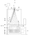
本発明の実施例1に係る紡糸巻取装置11について、図1から図4を用いて説明する。図1は実施例1に係る紡糸巻取装置11の正面図である。図1を参照して本実施例に係る紡糸巻取装置11の全体構成を説明する。紡糸巻取装置11は、主に紡糸装置12と巻取装置13とから構成されており、高温で溶解させた熱可塑性樹脂(ポリマー)を細いノズルから押し出し、冷却しながら巻き取って糸Yにする装置である。一般に紡糸巻取装置11には、POY(一部延伸糸)を巻取るPOY用紡糸巻取装置と、FDY(延伸糸)を巻取るFDY用紡糸巻取装置と、の2種類の装置がある。本発明に係る紡糸巻取装置11はPOY用紡糸巻取装置である。
A spinning and winding
紡糸装置12は、複数本のフィラメントを紡出し、紡出されたフィラメントを上方から下方に向けて供給するものである。紡糸装置12に投入された合繊原料(フィラメントの原料)は押出機を用いて圧送され、スピニングヘッド(図示略)に設けられた複数の紡出口から紡出する。スピニングヘッドの紡出口から紡出された複数のフィラメントは、所定の本数毎に束ねられて複数本の糸Yを構成し、巻取装置13へ導かれる。つまり、フィラメントを所定の本数束ねて成る糸Yが複数本構成されて、この複数本の糸Yが巻取装置13へ導かれるのである。
The
巻取装置13は、紡糸装置12からの複数本の糸Yを複数のボビンBで巻き取って、複数のパッケージPとするものである。巻取装置13は、糸Yの走行方向に沿って上流側から、第1糸道ガイド21、インターレース22、第1ローラ23、第2ローラ24、綾振支点ガイド25、及びパッケージ形成部15を備えている。
The winding
第1糸道ガイド21は、紡糸装置12からの複数本の糸Yの糸道を規定して、下流側のインターレース22に糸Yをガイドするものである。インターレース22は、流体噴射ノズルを用いることで糸Yを構成するフィラメントを相互に絡み合わせて集束性を付与し、繊維間の広がりや分離を抑制するものである。
The first yarn path guide 21 defines a plurality of yarn paths Y from the
第1ローラ23は紡糸装置12からの複数の糸Yを引き取るローラである。第1ローラ23の下流側には第2ローラ24が設けられている。第2ローラ24は、パッケージ形成部15に向けて糸Yを送り出すローラである。第2ローラ24は、昇降装置31により、複数の糸Yの糸道が巻取運転時における正規の糸道となる巻取運転位置aと、巻取運転位置aよりも低く、糸掛け作業を行い易い位置である糸掛け作業位置bとの間で移動可能である。昇降装置31については、後に詳しく説明する。
The
パッケージ形成部15は、第2ローラ24から綾振支点ガイド25を介して送り出された複数本の糸YをそれぞれのボビンBに巻き取るものである。パッケージ形成部15は、回転することによって糸Yを巻き取るボビンBと、複数のボビンBが装着されるボビンホルダ16と、ボビンBに巻き取られる糸Yを綾振するトラバース装置18と、ボビンBならびにボビンB上に形成されたパッケージPに圧接するタッチローラ(図示略)と、トラバース装置18やタッチローラを駆動する駆動装置17とから構成される。
The
第2ローラ24は、ボビンホルダ16の軸と直交するように配置されており、第1ローラ23から送糸された複数の糸Yを各巻取ボビンBに振り分ける際、各糸Yを第2ローラ24の接線方向に振り分ける。このため、第2ローラ24では糸Yは屈曲しない。第2ローラ24からパッケージ形成部15の方向に振り分けられた各糸Yは、綾振支点ガイド25を支点としてトラバース装置18によって左右方向(ボビンホルダ16の軸方向)に綾振されて回転するボビンBに巻き取られる。そして、ボビンBに巻き取られた糸Yは、ボビンB上にパッケージPを形成する。
The
ここで、昇降装置31について詳しく説明する。図1に示すように、昇降装置31は、本体フレーム14に固定されており、第2ローラ24を複数の糸Yの糸道が巻取運転時における正規の糸道となる巻取運転位置aと、巻取運転位置aよりも低く、オペレータが低い位置から糸掛け作業を行い易い位置である糸掛け作業位置bと、の間で移動させる装置である。第2ローラ24の巻取運転位置aは、綾振支点ガイド25における糸Yの屈曲角度が糸Yの品質を損なわない上限屈曲角度(例えば15度)以下となるように設定される。具体的には、各綾振支点ガイド25における糸Yの屈曲角はそれぞれ異なっており、ボビンホルダ16の両端側に対応する各綾振支点ガイド25における糸Yの屈曲角θが最大となる。この両端の綾振支点ガイド25における糸Yの屈曲角θが上限屈曲角度以下となるように第2ローラ24の巻取運転位置aが設定される。
Here, the lifting
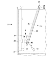
図2Aは昇降装置31の正面図、図2Bは図2AのB−B線における断面図を示している。昇降装置31は、プーリ32、33、ベルト34、及びレール35を備えている。プーリ32は、第2ローラ24の巻取運転位置aの上方に配置され、プーリ33は、第2ローラ24の糸掛け作業位置bの下方に配置されている。ベルト34はエンドレス帯であり、プーリ32、33に巻き掛けられている。ベルト34はチェーン等により構成されていてもよい。プーリ32には駆動源であるモータ36が取り付けられ、昇降装置31の下端にはモータ36の駆動の開始と停止、及びモータ36の駆動方向を切り換えるための操作スイッチ(図示せず)を配している。モータ36はプーリ33に取り付けてもよい。
2A is a front view of the
ベルト34には、連結部材37が固定されており、連結部材37には第2ローラ24の駆動源であるモータ24aが固定されている。従って、第2ローラ24は、ベルト34の駆動と共に移動する。レール35は巻取運転位置aから糸掛け作業位置bの方向に沿って設けられている。レール35の断面形状は略C字状であり、連結部材37に設けられた案内ローラ38がレール35の内側で案内されるように構成されている。これにより、ベルト34が上方又は下方に駆動すると、第2ローラ24はレール35に沿って移動する。レール35の上端部付近には、保持部材39が設けられている。保持部材39は、連結部材37に当接して第2ローラ24を巻取運転位置aで停止させるとともに、モータ36に対する電力供給を解除しても第2ローラ24が巻取運転位置aで静止するように連結部材37を保持する。レール35の下端部付近には停止部材40が設けられている。停止部材40は連結部材37に当接して第2ローラ24を糸掛け作業位置bで停止させる。
A connecting
続いて、昇降装置31を用いて第2ローラ24にオペレータが糸掛けを行う手順について図3、図4を用いて説明する。図3は、第2ローラ24を糸掛け作業位置bに移動させた状態を示す昇降装置31の拡大正面図、図4は、第2ローラ24を巻取運転位置aに移動させた状態を示す昇降装置31の拡大正面図である。紡糸装置12で紡糸された複数の糸Yは、サクションガン51を用いて第1ローラ23まで糸掛けが完了しているものとする。また、第2ローラ24への糸掛け作業に入る前に第2ローラ24を糸掛け作業位置bに移動させているものとする。第2ローラ24が糸掛け作業位置bにない場合は、オペレータは操作スイッチを操作してモータ36を駆動させ、第2ローラ24を糸掛け作業位置bに移動させる。
Next, a procedure for an operator to thread the
図3に示すように、糸掛け作業位置bにある第2ローラ24に対して、オペレータがサクションガン51を操作して糸Yを掛ける。糸掛け作業位置bにある第2ローラ24は低い位置にあり、第1糸道ガイド21、インターレース22、第1ローラ23に糸掛けを行ったオペレータは、同じ高さからサクションガン51を操作して第2ローラ24に糸を掛けることができる。
As shown in FIG. 3, the operator operates the
第2ローラ24に糸Yを掛けたら、次に図4に示すように、オペレータは操作スイッチを操作してモータ36を駆動させ、第2ローラ24を巻取運転位置aに移動させる。このとき、オペレータはサクションガン51を第2ローラ24に向けて保持しておく。第2ローラ24を巻取運転位置aに移動させているときは、紡糸装置12から供給される糸Yの走行速度と、サクションガン51で吸引される糸Yの速度、及び第2ローラ24が移動する速度とが釣り合っており、複数の糸Yのテンションが過度に変化することはない。このため、複数の糸Yが切断することなく、第2ローラ24を巻取運転位置aに移動させることができる。
When the yarn Y is applied to the
第2ローラ24が巻取運転位置aに到達すると、連結部材37が保持部材39に当接して第2ローラ24が巻取運転位置aで停止する。この状態でモータ36に対する電力供給を解除しても連結部材37は保持部材39に保持されているため、第2ローラ24は複数の糸Yが掛けられた状態で、巻取運転位置aで静止し、第2ローラ24への糸掛け作業が完了する。
When the
以上説明した実施例1に係る紡糸巻取装置11によれば、次のような効果を有する。
According to the
第2ローラ24は、昇降装置31により複数の糸Yの糸道が巻取運転時における正規の糸道となる巻取運転位置aと、巻取運転位置aよりも低い位置である糸掛け作業位置bとの間で移動可能であるため、糸掛け作業位置bで第2ローラ24に糸Yを掛け、その後、巻取運転位置aに移動させることにより、第2ローラ24に対して低い位置で糸掛け作業を行うことができる。しかも、糸Yを振り分けるために第2ローラ24を用いており、大きい屈曲角度で糸Yを変向させる必要がないため、各糸Yを各巻取りボビン位置に案内するためにローラを用いる必要がない。このため、糸掛け作業性が良好で、かつ耐久性の高い紡糸巻取装置とすることができる。
The
本発明の実施例2に係る紡糸巻取装置11について、図5と図6を用いて説明する。本実施例では第2糸道ガイド26を設けた点が実施例1とは大きく異なっている。
A
図5は、実施例2に係る紡糸巻取装置11の正面図である。実施例2の紡糸巻取装置11においても昇降装置31が設けられており、第2ローラ24は、昇降装置31により、複数の糸Yの糸道が巻取運転時における正規の糸道となる巻取運転位置aと、巻取運転位置aよりも低く、糸掛け作業を行い易い位置である糸掛け作業位置bとの間で移動可能である。昇降装置31の構成については実施例1と同様であるため、詳しい説明は省略する。
FIG. 5 is a front view of the
実施例1において説明したように、第2ローラ24の巻取運転位置aは、糸Yの屈曲角度が上限屈曲角度以下となるように設定される(図1参照)。実施例1では、糸Yが最大角度で屈曲するのはボビンホルダ16の両端に対応する綾振支点ガイド25であるため、この綾振支点ガイド25における糸Yの屈曲角が上限屈曲角度以下となるように第2ローラ24の巻取運転位置aは設定される。このため、第2ローラ24の巻取運転位置aは、ある高さ以下に設定することができず、巻取装置13の高さを低くできない原因となっていた。
As described in the first embodiment, the winding operation position a of the
本実施例では、第2ローラ24と綾振支点ガイド25との間に第2糸道ガイド26を設ける。第2糸道ガイド26は、第2ローラ24で各巻取ボビンに向けて振り分けた各糸を上限屈曲角度以下で屈曲させる糸道ガイドである。各糸Yを綾振支点ガイド25だけでなく第2糸道ガイド26でも屈曲させることで各糸を2段階に屈曲させ、合計の屈曲角度を綾振支点ガイド25のみによる糸Yの屈曲角度よりも大きくする。これにより、第2ローラ24の巻取運転位置aを低い位置に設定し、巻取装置の高さを低くすることができる。
In the present embodiment, a second yarn path guide 26 is provided between the
尚、第2ローラ24は、ボビンホルダ16の軸と直交するように配置されており、第1ローラ23から送糸された複数の糸Yを各巻取ボビンBに振り分ける際、各糸Yを第2ローラ24の接線方向に振り分ける。このため、第2ローラ24では糸Yは屈曲しておらず、第2ローラ24の巻取運転位置aを低い位置に設定する際に、第2ローラ24における屈曲角を考慮する必要はない。
The
また、実施例1において説明したように、各綾振支点ガイド25における糸Yの屈曲角はそれぞれ異なっている。この糸Yの屈曲角の相違は、各糸Yのテンションの差異となり、各糸Yの品質が微妙に異なる原因となる。そこで本実施例では、各糸Yが第2糸道ガイド26と綾振支点ガイド25とで屈曲する合計屈曲角度を各糸Y間で等しくなるように、第2糸道ガイド26を配置している。
Further, as described in the first embodiment, the bending angle of the yarn Y in each
図6Aは第2ローラ24から綾振支点ガイド25に到る糸Yの糸道を側方から見た図、図6Bは第2ローラ24から綾振支点ガイド25に到る糸Yの糸道を斜め上方から見た図である。第2糸道ガイド26は、図6A、図6Bに示すように、同一直線上ではなく、曲線上に配置されている。一方、綾振支点ガイド25はトラバース装置18に導かれる糸Yの支点であるため、同一直線上に配置されている。このとき、各第2糸道ガイド26において、各糸Yはそれぞれ異なる平面上で屈曲する。従って、各第2糸道ガイド26における各糸Yの屈曲角度は、図5の正面視において各糸Yが為す角度ではなく、図6Bに示すように、各糸Yの3次元的で実質的な屈曲角度θ11、θ12・・・θ110である。同様に、各綾振支点ガイド25における各糸Yの屈曲角度は、各糸Yの3次元的で実質的な屈曲角度θ21、θ22・・・θ210である。
6A is a side view of the yarn path of the yarn Y from the
そして、本実施例では、各糸Yの合計屈曲角度(θ11+θ21、θ12+θ22・・・θ110+θ210)が各糸Y間で等しくなり、かつ、各糸Yの合計屈曲角度(θ11+θ21、θ12+θ22・・・θ110+θ210)が上限屈曲角度より大きくなるように第2糸道ガイド26の位置を設定している。尚、各第2糸道ガイド26における各糸Yの屈曲角度θ11、θ12・・・θ110と、各綾振支点ガイド25における各糸Yの屈曲角度θ21、θ22・・・θ210がそれぞれ上限屈曲角度以下となるように第2糸道ガイド26の位置を設定するものとする。 In this embodiment, the total bending angle (θ11 + θ21, θ12 + θ22... Θ110 + θ210) of each yarn Y is equal between the yarns Y, and the total bending angle of each yarn Y (θ11 + θ21, θ12 + θ22... Θ110 + θ210). The position of the second yarn path guide 26 is set so that is larger than the upper limit bending angle. The bending angles θ11, θ12... Θ110 of each yarn Y in each second yarn path guide 26 and the bending angles θ21, θ22. The position of the second yarn path guide 26 is set so as to be as follows.
以上説明した実施例2に係る紡糸巻取装置11によれば、次のような効果を有する。
According to the
綾振支点ガイド25と糸道ガイドとで各糸Yを多段階に屈曲させ、合計屈曲角度(θ11+θ21、θ12+θ22・・・θ110+θ210)を上限屈曲角度より大きくできるため、第2ローラ24の高さを低く抑えることができる。このため、巻取装置13の高さを低くした、低床の紡糸巻取装置11とすることができる。
Since each yarn Y is bent in multiple stages by the
また、綾振支点ガイド25と第2糸道ガイド26による合計屈曲角度が、各糸Y間で等しくなるように、第2糸道ガイド26を配置したため、各糸Yのテンションを各糸Y間で等しくすることができ、各糸Y間の糸品質を均質にすることができる。
Further, since the second yarn path guide 26 is arranged so that the total bending angle by the
以上、本発明の実施の形態について説明したが、本発明は上記実施例に限定されるものではなく、様々な変更が可能である。例えば、昇降装置31はモータ36でプーリ32を駆動するものとしたが、手動でプーリ33を回転させるようにしてもよい。また、エアシリンダの伸縮駆動を用いて第2ローラ24を移動させるようにしてもよく、棒状の部材を用いて手動で第2ローラ24を移動させるようにしてもよい。
Although the embodiments of the present invention have been described above, the present invention is not limited to the above-described embodiments, and various modifications can be made. For example, although the
以上説明した本発明の技術的範囲は、上記実施例に限定されるものではなく、上記実施例の形状に限定されない。本発明の技術的範囲は、本明細書及び図面に記載した事項から明らかになる本発明が真に意図する技術的思想の範囲全体に、広く及ぶものである。 The technical scope of the present invention described above is not limited to the above embodiment, and is not limited to the shape of the above embodiment. The technical scope of the present invention broadly covers the entire scope of technical ideas that the present invention truly intends, as will be apparent from the matters described in the present specification and drawings.
11 紡糸巻取装置
12 紡糸装置
13 巻取装置
14 本体フレーム
15 パッケージ形成部
16 ボビンホルダ
17 駆動装置
18 トラバース装置
21 第1糸道ガイド
22 インターレース
23 第1ローラ
24 第2ローラ
24a モータ
25 綾振支点ガイド
26 第2糸道ガイド
31 昇降装置
32、33 プーリ
34 ベルト
35 レール
36 モータ
37 連結部材
38 案内ローラ
39 保持部材
40 停止部材
51 サクションガン
a 巻取運転位置
b 糸掛け作業位置
B ボビン
P パッケージ
Y 糸
DESCRIPTION OF
Claims (8)
前記巻取装置は、
前記紡糸装置からの複数の糸を引き取る第1ローラと、
前記紡糸装置からの複数の糸を巻き取るための巻取ボビンを複数支持するボビンホルダと、
前記ボビンホルダの軸と直交するように配置され、前記第1ローラから送糸された複数の糸を前記各巻取ボビンに振り分ける第2ローラと、
前記第2ローラから送糸される各糸を前記各巻取ボビンに対して綾振りする際の支点となる綾振支点ガイドと、
を備え、
前記第2ローラは、前記複数の糸の糸道が巻取運転時における正規の糸道となる巻取運転位置と、前記巻取運転位置よりも低い位置である糸掛け作業位置と、の間で移動可能であることを特徴とする紡糸巻取装置。 A spinning and winding device comprising a spinning device and a winding device,
The winding device
A first roller for picking up a plurality of yarns from the spinning device;
A bobbin holder for supporting a plurality of winding bobbins for winding a plurality of yarns from the spinning device;
A second roller that is arranged to be orthogonal to the axis of the bobbin holder and distributes the plurality of yarns fed from the first roller to the take-up bobbins;
A traverse fulcrum guide serving as a fulcrum when traversing each yarn fed from the second roller with respect to each winding bobbin;
With
The second roller includes a winding operation position where the yarn paths of the plurality of yarns become normal yarn paths during the winding operation, and a yarn hooking operation position that is lower than the winding operation position. Spinning and winding device characterized by being movable by
前記綾振支点ガイドと前記糸道ガイドとで前記各糸を多段階に屈曲させることを特徴とする請求項1に記載の紡糸巻取装置。 A yarn path guide that bends each yarn distributed to each take-up bobbin at a predetermined angle or less between the second roller and the traverse fulcrum guide;
The yarn winding device according to claim 1, wherein the yarn is bent in multiple stages by the traverse fulcrum guide and the yarn path guide.
前記レールは、前記巻取運転位置から前記糸掛け作業位置の方向に向かって設けられていることを特徴とする請求項1、4、5のいずれか1項に記載の紡糸巻取装置。The spinning winding device according to any one of claims 1, 4, and 5, wherein the rail is provided from the winding operation position toward the yarn hooking operation position.
前記保持部材は、前記レールに沿って移動した前記第2ローラを前記巻取運転位置で停止させるとともに、前記第2ローラを移動させるためのエネルギー供給を解除しても、前記第2ローラを前記巻取運転位置で静止させることを特徴とする請求項6に記載の紡糸巻取装置。The holding member stops the second roller moved along the rail at the winding operation position and releases the second roller even when the energy supply for moving the second roller is released. The spinning winding device according to claim 6, wherein the spinning winding device is stationary at a winding operation position.
Priority Applications (4)
| Application Number | Priority Date | Filing Date | Title |
|---|---|---|---|
| JP2010158892A JP5519435B2 (en) | 2010-07-13 | 2010-07-13 | Spinning and winding device |
| EP11169964.1A EP2407408B1 (en) | 2010-07-13 | 2011-06-15 | Filament yarn winding apparatus |
| CN201110180830.3A CN102330163B (en) | 2010-07-13 | 2011-06-30 | Filament yarn winding apparatus |
| CN201510161713.0A CN104711689B (en) | 2010-07-13 | 2011-06-30 | Filament yarn winding apparatus |
Applications Claiming Priority (1)
| Application Number | Priority Date | Filing Date | Title |
|---|---|---|---|
| JP2010158892A JP5519435B2 (en) | 2010-07-13 | 2010-07-13 | Spinning and winding device |
Publications (3)
| Publication Number | Publication Date |
|---|---|
| JP2012021241A JP2012021241A (en) | 2012-02-02 |
| JP2012021241A5 JP2012021241A5 (en) | 2013-07-11 |
| JP5519435B2 true JP5519435B2 (en) | 2014-06-11 |
Family
ID=44675436
Family Applications (1)
| Application Number | Title | Priority Date | Filing Date |
|---|---|---|---|
| JP2010158892A Active JP5519435B2 (en) | 2010-07-13 | 2010-07-13 | Spinning and winding device |
Country Status (3)
| Country | Link |
|---|---|
| EP (1) | EP2407408B1 (en) |
| JP (1) | JP5519435B2 (en) |
| CN (2) | CN102330163B (en) |
Cited By (1)
| Publication number | Priority date | Publication date | Assignee | Title |
|---|---|---|---|---|
| CN106917149A (en) * | 2015-10-30 | 2017-07-04 | 日本Tmt机械株式会社 | Automatic hanging wire device |
Families Citing this family (12)
| Publication number | Priority date | Publication date | Assignee | Title |
|---|---|---|---|---|
| JP2013184781A (en) * | 2012-03-07 | 2013-09-19 | Tmt Machinery Inc | Yarn take-up apparatus |
| JP5864338B2 (en) * | 2012-03-30 | 2016-02-17 | Tmtマシナリー株式会社 | Spinning and winding device and spinning and winding equipment |
| JP5860348B2 (en) * | 2012-06-19 | 2016-02-16 | Tmtマシナリー株式会社 | Spinning winder |
| JP6211379B2 (en) * | 2013-10-16 | 2017-10-11 | Tmtマシナリー株式会社 | Spinning winder |
| JP6393206B2 (en) * | 2014-02-05 | 2018-09-19 | Tmtマシナリー株式会社 | Yarn winding machine |
| CN105803550A (en) * | 2014-05-06 | 2016-07-27 | 福建锦江科技有限公司 | Silk yarn winding device |
| JP6681307B2 (en) * | 2015-10-30 | 2020-04-15 | Tmtマシナリー株式会社 | Spinning device |
| CN107130308B (en) * | 2016-02-29 | 2021-10-15 | 日本Tmt机械株式会社 | Spinning tractor |
| DE102017006689A1 (en) * | 2017-07-14 | 2019-01-17 | Oerlikon Textile Gmbh & Co. Kg | winding machine |
| CN107620130A (en) * | 2017-09-29 | 2018-01-23 | 北京中丽制机工程技术有限公司 | A kind of taking-up device for spinning |
| CN109733955A (en) * | 2019-02-25 | 2019-05-10 | 张家港锦亿化纤有限公司 | Dacron thread filar guide |
| DE102022112853B3 (en) * | 2021-06-04 | 2022-10-27 | Oerlikon Textile Gmbh & Co. Kg | Device for winding a bundle of threads |
Family Cites Families (16)
| Publication number | Priority date | Publication date | Assignee | Title |
|---|---|---|---|---|
| JPS5593778A (en) * | 1978-12-29 | 1980-07-16 | Toray Ind Inc | Thread winder |
| DE59209608D1 (en) * | 1991-10-26 | 1999-02-18 | Barmag Barmer Maschf | Process for pulling an endless synthetic thread |
| DE19581060D2 (en) * | 1994-09-21 | 1997-07-17 | Rieter Ag Maschf | Spinning machines |
| DE10235936A1 (en) | 2002-08-06 | 2004-02-19 | Barmag Ag | Synthetic textile spinning and spool winding assembly has line of spinning jets and a draw-down galette transverse to the line of winding stations |
| JP4128412B2 (en) * | 2002-08-20 | 2008-07-30 | Tstm株式会社 | Revolving type yarn winding machine |
| JP4176428B2 (en) * | 2002-09-17 | 2008-11-05 | Tstm株式会社 | Traverse device |
| CN1325357C (en) * | 2003-02-21 | 2007-07-11 | 苏拉有限及两合公司 | Apparatus for producing and winding synthetic multifilament yarns |
| JP2005067790A (en) * | 2003-08-22 | 2005-03-17 | Tmt Machinery Inc | Fiber machine |
| CN101336316B (en) * | 2006-01-26 | 2011-08-10 | 欧瑞康纺织有限及两合公司 | Apparatus for melt spinning and winding synthetic threads |
| EP2147137B1 (en) * | 2007-05-11 | 2013-01-16 | Oerlikon Textile GmbH & Co. KG | Device for melt-spinning and winding synthetic threads |
| JP4990681B2 (en) * | 2007-05-23 | 2012-08-01 | Tmtマシナリー株式会社 | Yarn winding machine |
| JP2008297078A (en) * | 2007-05-31 | 2008-12-11 | Tmt Machinery Inc | Thread winder |
| JP2010052930A (en) * | 2008-08-29 | 2010-03-11 | Tmt Machinery Inc | Thread winder |
| JP5356778B2 (en) * | 2008-11-06 | 2013-12-04 | Tmtマシナリー株式会社 | Spinning winder |
| JP5368061B2 (en) * | 2008-11-13 | 2013-12-18 | Tmtマシナリー株式会社 | Spinning and winding equipment |
| JP5107210B2 (en) * | 2008-11-13 | 2012-12-26 | Tmtマシナリー株式会社 | Spinning and winding equipment |
-
2010
- 2010-07-13 JP JP2010158892A patent/JP5519435B2/en active Active
-
2011
- 2011-06-15 EP EP11169964.1A patent/EP2407408B1/en active Active
- 2011-06-30 CN CN201110180830.3A patent/CN102330163B/en active Active
- 2011-06-30 CN CN201510161713.0A patent/CN104711689B/en active Active
Cited By (2)
| Publication number | Priority date | Publication date | Assignee | Title |
|---|---|---|---|---|
| CN106917149A (en) * | 2015-10-30 | 2017-07-04 | 日本Tmt机械株式会社 | Automatic hanging wire device |
| CN106917149B (en) * | 2015-10-30 | 2021-06-29 | 日本Tmt机械株式会社 | Automatic wire hanging device |
Also Published As
| Publication number | Publication date |
|---|---|
| CN102330163B (en) | 2015-05-13 |
| CN104711689A (en) | 2015-06-17 |
| CN102330163A (en) | 2012-01-25 |
| EP2407408B1 (en) | 2016-11-09 |
| EP2407408A2 (en) | 2012-01-18 |
| CN104711689B (en) | 2017-04-12 |
| EP2407408A3 (en) | 2015-09-16 |
| JP2012021241A (en) | 2012-02-02 |
Similar Documents
| Publication | Publication Date | Title |
|---|---|---|
| JP5519435B2 (en) | Spinning and winding device | |
| JP2012021241A5 (en) | ||
| JP4903226B2 (en) | Equipment for melt spinning and winding synthetic yarns | |
| EP2407407B1 (en) | Yarn threading method of take-up winding apparatus and take-up winding apparatus | |
| TWI324644B (en) | Apparatus for spinning and winding multifilament yarns | |
| JP5837064B2 (en) | Equipment for melt spinning, drawing and winding multiple multifilament yarns | |
| JP5479964B2 (en) | Spinning winding equipment and yarn winding method in spinning winding equipment | |
| JP2013067935A (en) | Spinning machine and method for interrupting yarn production on spinning machine | |
| JP2012214941A (en) | Spinning winder | |
| JP2013023787A (en) | Spinning winder | |
| JP2012097369A (en) | False-twist texturing machine | |
| JP2013067483A (en) | Spinning machine | |
| EP3153614A1 (en) | Spinning machine | |
| JP2013184781A (en) | Yarn take-up apparatus | |
| JP6133637B2 (en) | Spinning and drawing equipment | |
| JP2011144019A (en) | Yarn winder equipment | |
| CN104451924A (en) | Reeling device, spinning position and application of reeling device and spinning position in spandex fiber production | |
| JP2004323166A (en) | Yarn guide device for revolving type automatic winding machine | |
| EP2752512B1 (en) | Spinning machine | |
| JP2013519799A (en) | Device for drawing and winding a large number of synthetic yarns | |
| JP2017071870A (en) | Draft device, spinning machine, and spinning method | |
| JP2006348420A (en) | Method and apparatus for knotting fiber cord | |
| CN108411414A (en) | yarn winding machine | |
| CN210854757U (en) | Horizontal tension mechanism for polyester production | |
| EP2184386B1 (en) | Device for melt-spinning and winding up synthetic filament yarns |
Legal Events
| Date | Code | Title | Description |
|---|---|---|---|
| A521 | Request for written amendment filed |
Free format text: JAPANESE INTERMEDIATE CODE: A523 Effective date: 20130528 |
|
| A621 | Written request for application examination |
Free format text: JAPANESE INTERMEDIATE CODE: A621 Effective date: 20130528 |
|
| A977 | Report on retrieval |
Free format text: JAPANESE INTERMEDIATE CODE: A971007 Effective date: 20140311 |
|
| TRDD | Decision of grant or rejection written | ||
| A01 | Written decision to grant a patent or to grant a registration (utility model) |
Free format text: JAPANESE INTERMEDIATE CODE: A01 Effective date: 20140318 |
|
| A61 | First payment of annual fees (during grant procedure) |
Free format text: JAPANESE INTERMEDIATE CODE: A61 Effective date: 20140403 |
|
| R150 | Certificate of patent or registration of utility model |
Ref document number: 5519435 Country of ref document: JP Free format text: JAPANESE INTERMEDIATE CODE: R150 |
|
| R250 | Receipt of annual fees |
Free format text: JAPANESE INTERMEDIATE CODE: R250 |
|
| R250 | Receipt of annual fees |
Free format text: JAPANESE INTERMEDIATE CODE: R250 |
|
| R250 | Receipt of annual fees |
Free format text: JAPANESE INTERMEDIATE CODE: R250 |
|
| R250 | Receipt of annual fees |
Free format text: JAPANESE INTERMEDIATE CODE: R250 |
|
| R250 | Receipt of annual fees |
Free format text: JAPANESE INTERMEDIATE CODE: R250 |
|
| R250 | Receipt of annual fees |
Free format text: JAPANESE INTERMEDIATE CODE: R250 |
|
| R250 | Receipt of annual fees |
Free format text: JAPANESE INTERMEDIATE CODE: R250 |
|
| R250 | Receipt of annual fees |
Free format text: JAPANESE INTERMEDIATE CODE: R250 |