EP2573225A2 - Spinning unit and spinning machine - Google Patents
Spinning unit and spinning machine Download PDFInfo
- Publication number
- EP2573225A2 EP2573225A2 EP12180222A EP12180222A EP2573225A2 EP 2573225 A2 EP2573225 A2 EP 2573225A2 EP 12180222 A EP12180222 A EP 12180222A EP 12180222 A EP12180222 A EP 12180222A EP 2573225 A2 EP2573225 A2 EP 2573225A2
- Authority
- EP
- European Patent Office
- Prior art keywords
- yarn
- spun yarn
- pooling
- section
- spun
- Prior art date
- Legal status (The legal status is an assumption and is not a legal conclusion. Google has not performed a legal analysis and makes no representation as to the accuracy of the status listed.)
- Granted
Links
Images


Classifications
-
- D—TEXTILES; PAPER
- D01—NATURAL OR MAN-MADE THREADS OR FIBRES; SPINNING
- D01H—SPINNING OR TWISTING
- D01H4/00—Open-end spinning machines or arrangements for imparting twist to independently moving fibres separated from slivers; Piecing arrangements therefor; Covering endless core threads with fibres by open-end spinning techniques
- D01H4/48—Piecing arrangements; Control therefor
-
- B—PERFORMING OPERATIONS; TRANSPORTING
- B65—CONVEYING; PACKING; STORING; HANDLING THIN OR FILAMENTARY MATERIAL
- B65H—HANDLING THIN OR FILAMENTARY MATERIAL, e.g. SHEETS, WEBS, CABLES
- B65H51/00—Forwarding filamentary material
- B65H51/20—Devices for temporarily storing filamentary material during forwarding, e.g. for buffer storage
- B65H51/22—Reels or cages, e.g. cylindrical, with storing and forwarding surfaces provided by rollers or bars
-
- B—PERFORMING OPERATIONS; TRANSPORTING
- B65—CONVEYING; PACKING; STORING; HANDLING THIN OR FILAMENTARY MATERIAL
- B65H—HANDLING THIN OR FILAMENTARY MATERIAL, e.g. SHEETS, WEBS, CABLES
- B65H63/00—Warning or safety devices, e.g. automatic fault detectors, stop-motions ; Quality control of the package
- B65H63/06—Warning or safety devices, e.g. automatic fault detectors, stop-motions ; Quality control of the package responsive to presence of irregularities in running material, e.g. for severing the material at irregularities ; Control of the correct working of the yarn cleaner
- B65H63/062—Electronic slub detector
-
- B—PERFORMING OPERATIONS; TRANSPORTING
- B65—CONVEYING; PACKING; STORING; HANDLING THIN OR FILAMENTARY MATERIAL
- B65H—HANDLING THIN OR FILAMENTARY MATERIAL, e.g. SHEETS, WEBS, CABLES
- B65H67/00—Replacing or removing cores, receptacles, or completed packages at paying-out, winding, or depositing stations
- B65H67/08—Automatic end-finding and material-interconnecting arrangements
- B65H67/081—Automatic end-finding and material-interconnecting arrangements acting after interruption of the winding process, e.g. yarn breakage, yarn cut or package replacement
-
- B—PERFORMING OPERATIONS; TRANSPORTING
- B65—CONVEYING; PACKING; STORING; HANDLING THIN OR FILAMENTARY MATERIAL
- B65H—HANDLING THIN OR FILAMENTARY MATERIAL, e.g. SHEETS, WEBS, CABLES
- B65H2701/00—Handled material; Storage means
- B65H2701/30—Handled filamentary material
- B65H2701/31—Textiles threads or artificial strands of filaments
Definitions
- the present invention relates to a spinning unit that forms a spun yarn and winds the spun yarn to form a package, and a spinning machine that includes a plurality of such spinning units.
- Spinning units known to the inventor include a yarn supplying device that supplies a spun yarn, a winding device that winds the spun yarn to form a package, and a yarn pooling device that is arranged between the yarn supplying device and the winding device and that pools the spun yarn by winding the spun yarn on a yarn pooling roller.
- the inventors recognized that, in the spinning unit such as the one mentioned above, if an end of the spun yarn moves to an unanticipated region of the yarn pooling roller when a breakage in the spun yarn occurs, smooth operation of the spinning unit thereafter is likely to be adversely affected.
- a spinning unit includes a yarn supplying device that supplies a spun yarn; a winding device that winds the spun yarn to form a package; and a yarn pooling device that pools the spun yarn between the yarn supplying device and the winding device.
- the yarn pooling device includes a yarn pooling roller around which the spun yarn is wound, and a first regulating portion that is arranged facing a base end section on a winding start side of a yarn pooling section where the spun yarn is wound around the yarn pooling roller, and regulates a movement of an end of the spun yarn that sways about on the base end section side when a breakage of the spun yarn occurs on the yarn supplying device side, such that the swaying end of the spun yarn is prevented from moving to a tip end section side of the yarn pooling section before the spun yarn is orderly unwound from the tip end section side.
- a spinning machine includes a plurality of the above spinning units.
- a spinning machine 1 includes a plurality of spinning units 2, a yarn joining carrier 3, a blower box 4, and a motor box 5.
- the spinning units 2 are arranged side-by-side, and each spinning unit 2 forms a spun yarn Y and winds the spun yarn Y to form a package P.
- the yarn joining carrier 3 performs a yarn joining operation in the spinning unit 2 where a breakage of the spun yarn Y has occurred.
- the blower box 4 houses an air supplying source, and suchlike, that produces a suction flow, a swirling airflow, etc., in various parts of the spinning unit 2.
- the motor box 5 houses a motor, and suchlike, that supplies power to various parts of the spinning unit 2.
- upstream side refers to the side where the spun yarn Y is formed and the term “downstream side” refers to the side where the spun yarn Y is wound in a route in which the spun yarn Y runs (that is, a yarn path).
- front side is used for the side relative to the yarn joining carrier 3 where the yarn path is present and the term “backside” is used for the opposite side relative to the yarn joining carrier 3.
- each of the spinning units 2 includes, sequentially from the upstream side, a drafting device (yarn supplying device) 6, a spinning device (yarn supplying device) 7, a yarn clearer (yarn-defect detecting device) 8, a tension sensor (tension measuring device) 9, a yarn pooling device 50, a waxing device 11, and a winding device 12.
- a drafting device yarn supplying device
- a spinning device yarn supplying device
- yarn clearer yarn clearer
- tension sensor tension measuring device
- the yarn processing module 80 that is detachably mounted on the frame 13.
- the drafting device 6 drafts a sliver S to form a fiber bundle F (that is, drafts the fiber bundle F).
- the drafting device 6 includes a pair of back rollers 14, a pair of third rollers 15, a pair of middle rollers 17 with an apron belt 16 stretched over them, and a pair of front rollers 18.
- the bottom roller of each of the pairs of the rollers 14, 15, 17, and 18 is driven at different rotational speed by the power from the motor box 5 or a not shown electric motor arranged in each of the spinning units 2. Because of the rotation of the rollers 14, 15, 17, and 18, the drafting device 6 drafts the sliver S supplied from the upstream side to form the fiber bundle F, and supplies the fiber bundle F to the spinning device 7 located on the downstream side.
- the spinning device 7 is an air spinning device that twists the fiber bundle F using a swirling airflow to form the spun yarn Y. More specifically, the spinning device 7 includes the following not shown components: a spinning chamber, a fiber guiding section, a swirling-airflow producing nozzle, and a hollow guide shaft.
- the fiber guiding section guides the fiber bundle F supplied from the drafting device 6 on the upstream side into the spinning chamber.
- the swirling-airflow producing nozzle is arranged in the periphery of the route in which the fiber bundle F runs and produces the swirling airflow inside the spinning chamber.
- the swirling airflow causes yarn ends of the fiber bundle F guided into the spinning chamber to be reversed and whirled.
- the hollow guide shaft guides the spun yarn Y from inside the spinning chamber to outside of the spinning device 7.
- the yarn clearer 8 monitors the running spun yarn Y between the spinning device 7 and the yarn pooling device 50 for any yarn defect, and sends a yarn-defect detection signal to a unit controller 10 upon detection of the yarn defect. For example, an abnormality in a thickness of the spun yarn Y or a foreign matter that is included in the spun yarn Y is detected as a yarn defect by the yarn clearer 8.
- the tension sensor 9 measures a tension of the running spun yarn Y between the spinning device 7 and the yarn pooling device 50, and sends a tension signal indicative of the measured tension to the unit controller 10.
- the waxing device 11 applies wax to the running spun yarn Y between the yarn pooling device 50 and the winding device 12.
- One unit controller 10 is arranged in each of the spinning units 2 and controls operations of the spinning unit 2.
- the yarn pooling device 50 pools the running spun yarn Y between the spinning device 7 and the winding device 12.
- the yarn pooling device 50 has functions of stably drawing the spun yarn Y from the spinning device 7, preventing the spun yarn Y from slacking by pooling the spun yarn Y that is coming out of the spinning device 7 during the yarn joining operation by the yarn joining carrier 3, and preventing any variation in the tension of the spun yarn Y on the winding device 12 side from being conveyed to the spinning device 7 side by appropriately controlling the tension on the spun yarn Y on the winding device 12 side.
- the winding device 12 forms a fully wound package P by winding the spun yarn Y into a package P.
- the winding device 12 includes a cradle arm 21, a winding drum 22, and a traverse device 23.
- the cradle arm 21 is swingably supported by a support shaft 24.
- the cradle arm 21 causes a surface of a bobbin B, which is rotatably supported, or a surface of the package P (which is formed by winding the spun yarn Y on the bobbin B) to be in contact with a surface of the winding drum 22 with an appropriate pressure.
- the winding drum 22 is driven by the not shown electric motor included in each of the spinning units 2.
- the bobbin B and/or the package P that is in contact with the winding drum 22 also rotates.
- the traverse device 23 is driven by a shaft 25 that is common to a plurality of the spinning units 2, and causes the spun yarn Y to traverse a predetermined width on the rotating bobbin B and/or the package P.
- the yarn joining carrier 3 moves to the spinning unit 2 where a breakage of the spun yarn Y has occurred and performs the yarn joining operation at the particular spinning unit 2.
- the yarn joining carrier 3 includes a splicer (yarn joining device) 26, a suction pipe 27, and a suction mouth 28.
- the suction pipe 27 is pivotably supported by a support shaft 31.
- the suction pipe 27 holds the end of the spun yarn Y on the spinning device 7 side by suction and guides it to the splicer 26.
- the suction mouth 28 is pivotably supported by a support shaft 32.
- the suction mouth 28 holds the end of the spun yarn Y on the winding device 12 side by suction and guides it to the splicer 26.
- the splicer 26 joins two ends of the spun yarn Y that have been guided and brought together.
- the yarn pooling device 50 includes a yarn pooling roller 51, an electric motor (driving motor) 55, a pooled-yarn-amount lower limit sensor 56, a pooled-yarn-amount upper limit sensor 57, a yarn hooking member 61, a yarn taking-off member 64, a suction mechanism 65, and a regulating member 71.
- a first guiding member 78 and a yarn-operation control member 75 are arranged sequentially from the upstream side between the spinning device 7 and the yarn pooling roller 51.
- a second guiding member 79 is arranged between the yarn pooling roller 51 and the winding device 12.
- the yarn pooling roller 51 is fixed to a drive shaft of the electric motor 55 and is driven by the electric motor 55.
- the yarn pooling roller 51 includes a yarn pooling section 52, a base-end side tapering section 53, and a tip-end side tapering section 54.
- the yarn pooling section 52 is a cylindrical component around which the spun yarn Y is wound and tapers slightly towards the tip end.
- the base-end side tapering section 53 widens from a base end section 52a of the yarn pooling section 52 where winding starts towards the upstream side.
- the tip-end side tapering section 54 widens from a tip end section 52b of the yarn pooling section 52 towards the downstream side.
- the base-end side tapering section 53 receives the spun yarn Y being guided from the upstream side to the yarn pooling roller 51 and smoothly guides it to the base end section 52a of the yarn pooling section 52.
- the spun yarn Y is wound systematically from the base end side to the tip end side of the yarn pooling section 52.
- the tip-end side tapering section 54 prevents the occurrence of a phenomenon known as sloughing in which multiple coils of the spun yarn Y wound around the yarn pooling section 52 comes off all at once when the spun yarn Y is unwound from the yarn pooling roller 51 and smoothly guides the spun yarn Y from the yarn pooling roller 51 to the downstream side.
- the pooled-yarn-amount lower limit sensor 56 is a non-contact sensor that detects presence or absence of the spun yarn Y on the yarn pooling roller 51, and is arranged on the rear side of the yarn pooling roller 51 facing the yarn pooling section 52.
- the pooled-yarn-amount lower limit sensor 56 sends a pooled-amount lower limit detection signal to the unit controller 10 when an amount of the spun yarn Y wound around the yarn pooling roller 51 reaches a lower limit.
- the pooled-yarn-amount upper limit sensor 57 is a non-contact sensor that detects presence or absence of the spun yarn Y on the yarn pooling roller 51, and is arranged by the side of the yarn pooling roller 51 facing the tip end section 52b of the yarn pooling section 52.
- the pooled-yarn-amount upper limit sensor 57 sends a pooled-amount upper limit detection signal to the unit controller 10 when an amount of the spun yarn Y wound around the yarn pooling roller 51 reaches an upper limit.
- the yarn hooking member 61 is arranged on the winding device 12 side with respect to the yarn pooling roller 51, and engages with the spun yarn Y and winds it around the yarn pooling roller 51.
- the yarn hooking member 61 includes a flier shaft 62 and a flier 63.
- the flier shaft 62 is supported on the tip end side of the yarn pooling roller 51 so as to rotate relative to and coaxially with the yarn pooling roller 51.
- the flier 63 is fixed to the tip end of the flier shaft 62 and is bent over the tip-end side tapering section 54 of the yarn pooling roller 51 so as to be able to engage with the spun yarn Y.
- a magnetic force is caused to act between the yarn pooling roller 51 and the flier shaft 62.
- the yarn hooking member 61 produces a torque greater than or equal to a predetermined value.
- the yarn taking-off member 64 takes off the spun yarn Y from the yarn hooking member 61, and is arranged near the tip-end side tapering section 54 of the yarn pooling roller 51.
- the yarn taking-off member 64 is supported so as to be swingable between a descent position and an ascent position.
- the descent position is a position that is retracted from the yarn path.
- the ascent position is a position at which the spun yarn Y is pushed up in the yarn path and taken off from the yarn hooking member 61.
- the yarn taking-off member 64 is normally biased to be in the descent position side by a not shown spring. However, during the yarn joining operation, and suchlike, the yarn taking-off member 64 is moved to the ascent position by a not shown air pressure cylinder provided in the yarn joining carrier 3.
- the suction mechanism 65 produces a suction airflow in a suction vent 66a arranged facing the base-end side tapering section 53 of the yarn pooling roller 51.
- the suction vent 66a is provided at one end of a pipe-shaped member 66.
- the other end of the pipe-shaped member 66 is connected via a not shown pipe to a not shown fiber-waste collecting chamber, which is common to the suction pipe 27, and the suction mouth 28.
- the end of the spun yarn Y sways about on the base end section 52a side of the yarn pooling section 52.
- the swaying yarn end is subjected to the action of the suction airflow produced at the suction vent 66a.
- most fiber waste from the yarn end is removed by the suction mechanism 65 and is prevented from being scattered.
- the regulating member 71 is a plate member that is arranged beside the yarn pooling roller 51 (facing the yarn pooling section 52), and includes a first regulating portion 72, a second regulating portion 73, and a third regulating portion 74.
- the first regulating portion 72 and the second regulating portion 73 regulate the movement of the end of the spun yarn Y that sways about on the base end section 52a side of the yarn pooling section 52 when a breakage of the spun yarn Y occurs on the spinning device 7 side, such that the swaying end of the spun yarn Y is prevented from moving to the tip end section 52b side of the yarn pooling section 52 before the spun yarn Y is orderly unwound from the tip end section 52b of the yarn pooling section 52.
- the third regulating portion 74 regulates the movement of the end of the spun yarn Y that sways about on the tip end section 52b side of the yarn pooling section 52 when a breakage of the spun yarn Y occurs on the winding device 12 side, such that the swaying end of the spun yarn Y is prevented from moving to the base end section 52a side of the yarn pooling section 52 before the spun yarn Y is orderly unwound from the base end section 52a of the yarn pooling section 52.
- the yarn-operation control member 75 is a plate member mounted at the upstream of the yarn pooling roller 51 (in the present embodiment, on the bottom surface (end face on the downstream side) of the tension sensor 9), and includes a guiding component 76 and a regulating component 77.
- the guiding component 76 applies tension to the spun yarn Y and guides the spun yarn Y to the base-end side tapering section 53 of the yarn pooling roller 51, and prevents the twisting of the spun yarn Y coming from the spinning device 7 from being conveyed further downstream of the guiding component 76.
- the regulating component 77 prevents the end of the spun yarn Y from being displaced from the yarn path of the spun yarn Y guided to the yarn pooling device 50 and from moving to the yarn hooking member 61 side by passing over the yarn pooling roller 51.
- the first guiding member 78 is a plate member mounted at the upstream of the yarn pooling roller 51 (in the present embodiment, on the bottom surface (end face on the downstream side) of the tension sensor 9), and guides the spun yarn Y from a slit formed on a casing of the tension sensor 9 to a designated detection position inside the casing.
- the second guiding member 79 is a plate member mounted downstream of the yarn pooling roller 51 (in the present embodiment, on a module frame 81 of the yarn processing module 80).
- the second guiding member 79 guides the spun yarn Y to a designated position of the waxing device 11 and regulates a track of the spun yarn Y being swayed about by the rotating yarn hooking member 61, stabilizing the running of the spun yarn Y further downstream of the second guiding member 79.
- the electric motor 55 drives the yarn pooling roller 51 at a substantially constant rotational speed.
- the yarn hooking member 61 integrally rotates with the yarn pooling roller 51, and the flier 63 engages with the spun yarn Y.
- the yarn hooking member 61 which is rotating with the spun yarn Y engaged thereon, winds the spun yarn Y around the rotating yarn pooling roller 51.
- the unit controller 10 exerts control over the operation of the spinning unit 2.
- the unit controller 10 exerts this control based on the pooled-amount lower limit detection signal received from the pooled-yarn-amount lower limit sensor 56 and the pooled-amount upper limit detection signal received from the pooled-yarn-amount upper limit sensor 57, so that the pooled amount of the spun yarn Y that is wound around the yarn pooling roller 51 is greater than or equal to the lower limit and less than or equal to the upper limit.
- the yarn pooling device 50 can draw the spun yarn Y stably (that is, while maintaining a substantially constant quality and speed) from the spinning device 7 by the rotation of the yarn pooling roller 51.
- a force that causes the yarn hooking member 61 to rotate relative to the yarn pooling roller 51 acts on the flier 63.
- the torque produced in the yarn hooking member 61 increases to a value greater than or equal to a predetermined value as a consequence of the force, the yarn hooking member 61 rotates relative to the yarn pooling roller 51. Consequently, the spun yarn Y is unwound from the yarn pooling roller 51.
- the yarn hooking member 61 rotates integrally with the yarn pooling roller 51. Consequently, the spun yarn Y is wound around the yarn pooling roller 51. In this manner, the yarn pooling device 50 adjusts the tension on the spun yarn Y on the winding device 12 side and thereby prevents the variation in the tension on the spun yarn Y that occurs on the winding device 12 side from being conveyed to the spinning device 7 side.
- the yarn clearer 8 detects a defect while the spinning unit 2 is operating normally by forming the spun yarn Y and winding the spun yarn Y to form the package P, the yarn clearer 8 sends the yarn-defect detection signal to the unit controller 10.
- the unit controller 10 stops the operation of the drafting device 6, the spinning device 7, etc., immediately upon receiving the yarn-defect detection signal. Consequently, the fiber bundle F is not subjected to twisting, and the spun yarn Y is cut on the spinning device 7 side.
- the unit controller 10 causes the rotation of the yarn pooling roller 51 and the winding by the winding device 12 to be continued. Consequently, as shown in FIG. 4 , the cut end of the spun yarn Y is wound around the yarn pooling roller 51. While the spun yarn Y is unwound from the yarn pooling roller 51 to the winding device 12, the cut end of the spun yarn Y sways about on the base end section 52a side of the yarn pooling section 52. The swaying yarn end is prevented from moving to the tip end section 52b of the yarn pooling section 52 by the first regulating portion 72 of the regulating member 71, and is subjected to the suction airflow produced by the suction vent 66a.
- the spun yarn Y is smoothly unwound from the yarn pooling roller 51 to the winding device 12 side.
- the fiber waste from the yarn end on the upstream side is removed by the suction mechanism 65 and is prevented from being scattered.
- the unit controller 10 sends a control signal that specifies the spinning unit 2 in which the spun yarn Y has been cut to the yarn joining carrier 3. Consequently, the yarn joining carrier 3 moves to a position in front of the specified spinning unit 2, and commences the yarn joining operation.
- the suction mouth 28 turns to a position near the surface of the package P and produces the suction airflow while the winding device 12 causes a reverse rotation of the package P. Consequently, the suction mouth 28 draws and holds by suction the end of the spun yarn Y from the surface of the package P. Thereafter, as shown in FIG. 6 , the suction mouth 28 turns to its original position (standby position) and guides the end of the spun yarn Y on the winding device 12 side into the splicer 26. The winding device 12 stops the rotation of the package P.
- the suction pipe 27 pivots to a position at the downstream of the spinning device 7 and produces the suction airflow. Because during this operation the unit controller 10 restarts the operations of the drafting device 6, the spinning device 7, etc., the suction pipe 27 holds the end of the spun yarn Y that is formed. Thereafter, as shown in FIG. 6 , the suction pipe 27 pivots to the original position (standby position), and guides the end of the spun yarn Y on the spinning device 7 side to the splicer 26.
- the yarn hooking member 61 in the yarn pooling device 50 engages with the spun yarn Y on the spinning device 7 side and winds the spun yarn Y around the yarn pooling roller 51 with which the yarn hooking member 61 is integrally rotating. Consequently, almost no slack occurs in the spun yarn Y coming out of the spinning device 7, even if the winding by the winding device 12 is stopped.
- the yarn pooling device 50 pools the spun yarn Y coming out of the spinning device 7, thereby preventing the spun yarn Y from slacking.
- the unit controller 10 causes the yarn taking-off member 64 to move from the descent position to the ascent position where the yarn taking-off member 64 take off the spun yarn Y from the yarn hooking member 61.
- the unit controller 10 causes the yarn taking-off member 64 to move from the ascent position to the descent position. Consequently, the spun yarn Y on the spinning device 7 side is engaged by the yarn hooking member 61, and no unwinding of the spun yarn Y at the downstream of the yarn pooling roller 51 occurs.
- the splicer 26 joins the end of the spun yarn Y on the winding device 12 side and the end of the spun yarn Y on the spinning device 7 side. Unnecessary yarn ends cut by the splicer 26 are removed by the suction pipe 27 and the suction mouth 28. Once the yarn joining operation by the splicer 26 is completed, the unit controller 10 causes the winding operation by the winding device 12 to restart.
- the unit controller 10 causes the rotation of the yarn pooling roller 51 and the winding by the winding device 12 to be continued. Consequently, the cut end of the spun yarn Y is wound around the yarn pooling roller 51 and sways about on the base end section 52a side of the yarn pooling section 52. The yarn end is prevented from moving to the tip end section 52b side of the yarn pooling section 52 by the first regulating portion 72 of the regulating member 71, and is subjected to the suction airflow produced by the suction vent 66a. Consequently, the fiber waste from the yarn end on the upstream side is removed by the suction mechanism 65 and is prevented from being scattered.
- the unit controller 10 causes the yarn pooling roller 51 to stop positive rotation (rotation in the normal direction) and start reverse rotation.
- the upstream end of the spun yarn Y wound around the yarn pooling roller 51 is prevented from moving to the tip end section 52b side of the yarn pooling section 52 by the second regulating portion 73 of the regulating member 71. Consequently, as shown in FIG. 8 , the upstream yarn end is reliably held by suction by the suction vent 66a of the suction mechanism 65.
- the downstream end of the spun yarn Y wound around the yarn pooling roller 51 is prevented from moving to the base end section 52a side of the yarn pooling section 52 by the third regulating portion 74 of the regulating member 71. Therefore, the spun yarn Y wound around the yarn pooling roller 51 is smoothly unwound from the base end section 52a side of the yarn pooling section 52 and sucked in by the suction mechanism 65.
- the unit controller 10 causes the yarn pooling roller 51 to stop the reverse rotation and start the positive rotation.
- the unit controller 10 sends a control signal that specifies the spinning unit 2 in which the spun yarn Y has been cut to the yarn joining carrier 3. Consequently, the yarn joining carrier 3 moves to a position in front of the specified spinning unit 2, and performs the yarn joining operation.
- the first regulating portion 72, the second regulating portion 73, and the third regulating portion 74 of the regulating member 71 are integrally formed as parts of a rectangular plate member 70 made of, for example, metal.
- An upper edge 70a of the plate member 70 has a notch 70b.
- the suction vent 66a of the suction mechanism 65 faces the base-end side tapering section 53 of the yarn pooling roller 51 via the notch 70b.
- a lower edge 70c of the plate member 70 is bent toward the side opposite to that of the yarn pooling roller 51.
- the pooled-yarn-amount upper limit sensor 57 is mounted on the underside of the lower edge 70c.
- the first regulating portion 72 is located at the upstream of the notch 70b in a rotation direction A of the yarn pooling roller 51 during the winding of the spun yarn Y, that is, at the upstream of the suction vent 66a in the rotation direction A.
- the first regulating portion 72 is arranged facing the base end section 52a of the yarn pooling section 52.
- the first regulating portion 72 regulates the movement of the end of the spun yarn Y that sways about on the base end section 52a side of the yarn pooling section 52 when a breakage of the spun yarn Y occurs on the spinning device 7 side, such that the swaying end of the spun yarn Y is prevented from moving to the tip end section 52b side of the yarn pooling section 52 before the spun yarn Y is orderly unwound from the tip end section 52b of the yarn pooling section 52.
- the second regulating portion 73 is located downstream of the notch 70b in the rotation direction A of the yarn pooling roller 51 during the winding of the spun yarn Y, that is, at the downstream of the suction vent 66a in the rotation direction A.
- the second regulating portion 73 is arranged facing the base end section 52a of the yarn pooling section 52.
- the second regulating portion 73 regulates the movement of the end of the spun yarn Y that sways about on the base end section 52a side of the yarn pooling section 52 when a breakage of the spun yarn Y occurs on the spinning device 7 side, such that the swaying end of the spun yarn Y is prevented from moving to the tip end section 52b side of the yarn pooling section 52 before the spun yarn Y is orderly unwound from the tip end section 52b of the yarn pooling section 52.
- the location of the first regulating portion 72 at the upstream of the suction vent 66a in the rotation direction A implies that a distance from the suction vent 66a to the first regulating portion 72 is shorter when the yarn pooling roller 51 rotates in the direction opposite to the rotation direction A compared to when the yarn pooling roller 51 rotates in the rotation direction A.
- the location of the second regulating portion 73 at the downstream of the suction vent 66a in the rotation direction A implies that the distance from the suction vent 66a to the second regulating portion 73 is shorter when the yarn pooling roller 51 rotates in the rotation direction A compared to when the yarn pooling roller 51 rotates in the direction opposite to the rotation direction A.
- the third regulating portion 74 is located below the notch 70b (on the tip end section 52b side), that is, below the suction vent 66a (on the tip end section 52b side) and arranged facing the yarn pooling section 52.
- the third regulating portion 74 regulates the movement of the end of the spun yarn Y that sways about on the tip end section 52b side of the yarn pooling section 52 when a breakage of the spun yarn Y occurs on the winding device 12 side, such that the swaying end of the spun yarn Y is prevented from moving to the base end section 52a side of the yarn pooling section 52 before the spun yarn Y is orderly unwound from the base end section 52a of the yarn pooling section 52.
- the third regulating portion 74 is a part of the plate member 70 that is formed into a convex portion protruding towards the yarn pooling section 52 side.
- the third regulating portion 74 extends substantially parallel to a center line of rotation of the yarn pooling roller 51 along the yarn pooling section 52.
- the swaying end of the spun yarn Y on the base end section 52a side of the yarn pooling section 52 when a breakage in the spun yarn Y occurs on the spinning device 7 side (that is, on the side from where the spun yarn Y is guided-in to the yarn pooling roller 51) during yarn defect detection, etc., is prevented from moving to the tip end section 52b side of the yarn pooling section 52 by the first regulating portion 72 and the second regulating portion 73.
- the yarn pooling roller 51 when the yarn pooling roller 51 is reverse-rotated so as to unwind the spun yarn Y from the base end section 52a side of the yarn pooling section 52, the swaying end of the spun yarn Y on the tip end section 52b side of the yarn pooling section 52 when a breakage of the spun yarn Y occurs on the winding device 12 side (that is, on the side from where the spun yarn Y is guided-out from the yarn pooling roller 51) is prevented from moving to the base end section 52a side of the yarn pooling section 52 by the third regulating portion 74 that extends substantially parallel to the center line of rotation of the yarn pooling roller 51 along the yarn pooling section 52.
- the first regulating portion 72 is located at the upstream of the suction vent 66a of the suction mechanism 65 and the second regulating portion 73 is located downstream of the suction vent 66a of the suction mechanism 65 in the normal rotation direction of the yarn pooling roller 51. Consequently, because the end of the spun yarn Y that is swaying about on the base end section 52a side of the yarn pooling section 52 is subjected to the action of the suction airflow, the fiber waste at the end of the spun yarn Y can be reliably removed. Furthermore, the end of the spun yarn Y can be prevented from entangling around the suction vent 66a.
- the first regulating portion 72, the second regulating portion 73, and the third regulating portion 74 are integrally formed as parts of the plate member 70. Consequently, the number of parts required in the yarn pooling device 50 for providing the first regulating portion 72, the second regulating portion 73, and the third regulating portion 74 can be reduced, and simplification of the structure can be realized.
- One part of the plate member 70 that forms a convex portion protruding towards the yarn pooling section 52 side serves as the third regulating portion 74. Consequently, a narrower gap that needs to be maintained between the surface of the yarn pooling section 52 and the third regulating portion 74 can be easily and reliably ensured.
- the pooled-yarn-amount upper limit sensor 57 is mounted on the plate member 70. Consequently, the number of parts required for supporting the pooled-yarn-amount upper limit sensor 57 can be reduced, and simplification of the structure can be realized.
- the yarn supplying device that supplies the spun yarn Y includes the drafting device 6 and the spinning device 7.
- the spinning device 7 is an air spinning device that forms the spun yarn Y by twisting the fiber bundle F using a swirling airflow. Consequently, a high quality spun yarn Y can be efficiently supplied.
- the spinning machine 1 includes a plurality of the spinning units 2 that can operate smoothly as explained above even when a breakage occurs in the spun yarn Y, a high quality package P is efficiently formed.
- the present invention is not limited to these embodiments.
- the drafting device 6 and the spinning device 7 serve as the yarn supplying devices for supplying the spun yarn.
- any other yarn supplying device such as, a yarn supplying device that supplies the spun yarn from a bobbin having the spun yarn wound thereon, can be used.
- the spinning device is an air spinning device
- a needle that is held by a fiber guiding section to project into the spinning chamber can be further provided to prevent the twisting of the fiber bundle to be conveyed upstream of the spinning device.
- the twisting of the fiber bundle can be prevented from being conveyed upstream of the spinning device by a downstream end of a fiber guiding section instead of by the needle.
- the spinning device can include a pair of air-jet nozzles that produce airflows in mutually opposite directions, and can thus spin the fiber bundle in opposite directions at the same time.
- the yarn pooling device 50 has a function of drawing the spun yarn Y from the spinning device 7.
- the spun yarn can be drawn from a yarn supplying device that supplies the spun yarn by a delivery roller and a nip roller.
- the spun yarn Y is cut by a stoppage of the swirling airflow in the spinning device 7 during the yarn-defect detection operation.
- the spun yarn can be cut by a cutter during the yarn-defect detection operation.
- the devices are arranged so that the spun yarn Y supplied from above is wound below.
- the devices can be arranged so that the spun yarn supplied from below is wound above.
- the bottom rollers of the drafting device 6 and a traverse mechanism of the traverse device 23 are driven by the power of the motor box 5 (that is, concurrently driven in a plurality of the spinning units 2).
- each section (for example, the drafting device, the spinning device, the winding device, etc.) of the spinning unit can be driven independently in each spinning unit 2.
- the tension sensor 9 can be arranged at the upstream of the yarn clearer 8 in the running direction of the spun yarn Y.
- a common unit controller 10 can be provided for a plurality of the spinning units 2 instead of one unit controller 10 per spinning unit 2.
- the waxing device 11, the tension sensor 9, and the yarn clearer 8 need not be provided in the spinning unit 2.
- the winding device 12 can be driven by a common drive source provided for a plurality of the spinning units 2 instead of by a separate driving motor provided for each spinning unit 2. In this case, during the reverse rotation of the package P, the cradle arm 21 is moved by a not shown air cylinder so that the package P is separated from the winding drum 22, and thereafter the package P is reverse-rotated by a not shown reverse roller provided in the yarn joining carrier 3.
- the yarn clearer 8, the tension sensor 9, the yarn pooling device 50, and the waxing device 11 can be mounted individually on the frame 13 directly or indirectly.
- a spinning unit includes a yarn supplying device that supplies a spun yarn, a winding device that winds the spun yarn to form a package, and a yarn pooling device that pools the spun yarn between the yarn supplying device and the winding device.
- the yarn pooling device includes a yarn pooling roller around which the spun yarn is wound, and a first regulating portion. The first regulating portion is arranged facing a base end section on a winding start side of a yarn pooling section where the spun yarn is wound around the yarn pooling roller.
- the first regulating portion regulates a movement of an end of the spun yarn that sways about on the base end section side when a breakage of the spun yarn occurs on the yarn supplying device side, such that the swaying end of the spun yarn is prevented from moving to a tip end section side before the spun yarn is orderly unwound from the tip end section side of the yarn pooling section.
- the first regulating portion prevents the swaying end of the spun yarn on the base end section side of the yarn pooling section when a breakage of the spun yarn occurs on the yarn supplying device side from moving to the tip end section side of the yarn pooling section. Consequently, hindrance to a smooth unwinding of the spun yarn from the tip end section side of the yarn pooling section due to the entwining of the end of the spun yarn with the spun yarn wound on the tip end section side of the yarn pooling section is prevented.
- a smooth operation is realized by the spinning machine by regulating the end of the spun yarn in which breakage has occurred.
- the yarn pooling device can further include a suction mechanism that generates a suction airflow at a suction vent arranged facing the yarn pooling roller.
- the suction vent can be located downstream of the first regulating portion with respect to a rotation direction of the yarn pooling roller during the winding of the spun yarn. Consequently, because the end of the spun yarn that is swaying about on the base end section side of the yarn pooling section is subjected to the action of the suction airflow, fiber waste at the end of the spun yarn can be reliably removed. Furthermore, the end of the spun yarn can be prevented from entangling around the suction vent.
- the yarn pooling device can further include a second regulating portion.
- the second regulating portion is arranged facing the base end section of the yarn pooling section.
- the second regulating portion regulates a movement of the end of the spun yarn that sways about on the base end section side when a breakage of the spun yarn occurs on the yarn supplying device side, such that the swaying end of the spun yarn is prevented from moving to the tip end section side before the spun yarn is orderly unwound from the tip end section side.
- the second regulating portion is located downstream of the suction vent with respect to the rotation direction of the yarn pooling roller during the winding of the spun yarn.
- the yarn pooling device can further include a third regulating portion.
- the third regulating portion is arranged facing the yarn pooling section.
- the third regulating portion regulates a movement of the end of the spun yarn that sways about on the tip end section side when a breakage of the spun yarn occurs on the winding device side, such that the swaying end of the spun yarn is prevented from moving to the base end section side before the spun yarn is orderly unwound from the base end section side.
- the third regulating portion can extend substantially parallel to a center line of rotation of the yarn pooling roller along a surface of the yarn pooling section. Consequently, hindrance to a smooth unwinding of the spun yarn from the base end section side of the yarn pooling section due to the entwining of the end of the spun yarn with the spun yarn wound on the base end section side of the yarn pooling section is even more reliably prevented.
- the first regulating portion, the second regulating portion, and the third regulating portion can be integrally formed as parts of a plate member. Consequently, the number of parts required for providing the first regulating portion, the second regulating portion, and the third regulating portion can be reduced, and simplification of the structure can be realized.
- the third regulating portion can be a part of the plate member that is formed into a convex portion protruding towards the yarn pooling section side. Consequently, a narrower gap that needs to be maintained between the surface of the yarn pooling section and the third regulating portion can be easily and reliably ensured.
- the yarn pooling device can further include a pooled-yarn amount sensor that detects a pooled amount of the spun yarn wound around the yarn pooling roller and the pooled-yarn amount sensor can be mounted on the plate member. Consequently, the number of parts required for supporting the pooled-yarn amount sensor can be reduced, and simplification of the structure can be realized.
- the yarn supplying device can include a drafting device that drafts a fiber bundle and a spinning device that forms the spun yarn by twisting the fiber bundle. Consequently, a high quality spun yarn can be efficiently supplied.
- the spinning device can be an air spinning device that forms the spun yarn by twisting the fiber bundle using a swirling airflow. Consequently, a high quality spun yarn can be efficiently supplied.
- a spinning machine includes a plurality of the above-explained spinning units. Because the spinning machine includes the spinning units that can operate smoothly as explained above even when a breakage occurs in the spun yarn, a high quality package is efficiently formed.
Abstract
Description
- The present invention relates to a spinning unit that forms a spun yarn and winds the spun yarn to form a package, and a spinning machine that includes a plurality of such spinning units.
- Spinning units known to the inventor (for example, Japanese Patent Application Laid-open No.
2010-174421 - The inventors recognized that, in the spinning unit such as the one mentioned above, if an end of the spun yarn moves to an unanticipated region of the yarn pooling roller when a breakage in the spun yarn occurs, smooth operation of the spinning unit thereafter is likely to be adversely affected.
- It is an object of the present invention to provide a spinning unit that can operate smoothly by regulating movement of an end of a broken spun yarn, and a spinning machine that includes a plurality of such spinning units.
- A spinning unit according to an aspect includes a yarn supplying device that supplies a spun yarn; a winding device that winds the spun yarn to form a package; and a yarn pooling device that pools the spun yarn between the yarn supplying device and the winding device. The yarn pooling device includes a yarn pooling roller around which the spun yarn is wound, and a first regulating portion that is arranged facing a base end section on a winding start side of a yarn pooling section where the spun yarn is wound around the yarn pooling roller, and regulates a movement of an end of the spun yarn that sways about on the base end section side when a breakage of the spun yarn occurs on the yarn supplying device side, such that the swaying end of the spun yarn is prevented from moving to a tip end section side of the yarn pooling section before the spun yarn is orderly unwound from the tip end section side.
- A spinning machine according to an aspect includes a plurality of the above spinning units.
- The above and other objects, features, advantages and the technical and industrial significance of this invention will be better understood by reading the following detailed description of presently preferred embodiments of the invention, when considered in connection with the accompanying drawings.
-
-
FIG. 1 is a front view of a spinning machine according to an embodiment of the present invention; -
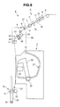
FIG. 2 is a side view of a spinning unit according to an embodiment of the present invention; -
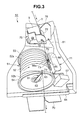
FIG. 3 is a perspective view of a yarn pooling device of the spinning unit shown inFIG. 2 ; -
FIG. 4 is a perspective view of the yarn pooling device during a yarn-defect detection operation; -
FIG. 5 is a side view of the spinning unit during the yarn-defect detection operation; -
FIG. 6 is another side view of the spinning unit during the yarn-defect detection operation; -
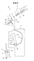
FIG. 7 is a side view of the spinning unit when a breakage of a yarn has occurred; -
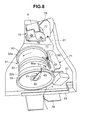
FIG. 8 is a perspective view of the yarn pooling device when a breakage of a yarn has occurred; -
FIG. 9 depicts a regulating member of the yarn pooling device shown inFIG. 3 from the side of a yarn pooling roller; and -
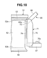
FIG. 10 is a front view of the regulating member of the yarn pooling device shown inFIG. 3 . - Exemplary embodiments of the present invention are explained in detail below with reference to the accompanying drawings. In the drawings, the parts that are identical or equivalent have been assigned the same reference numerals and the description thereof is not repeated.
- As shown in
FIG. 1 , a spinning machine 1 includes a plurality ofspinning units 2, ayarn joining carrier 3, ablower box 4, and amotor box 5. Thespinning units 2 are arranged side-by-side, and eachspinning unit 2 forms a spun yarn Y and winds the spun yarn Y to form a package P. Theyarn joining carrier 3 performs a yarn joining operation in thespinning unit 2 where a breakage of the spun yarn Y has occurred. Theblower box 4 houses an air supplying source, and suchlike, that produces a suction flow, a swirling airflow, etc., in various parts of thespinning unit 2. Themotor box 5 houses a motor, and suchlike, that supplies power to various parts of thespinning unit 2. - In the following explanation, the term "upstream side" refers to the side where the spun yarn Y is formed and the term "downstream side" refers to the side where the spun yarn Y is wound in a route in which the spun yarn Y runs (that is, a yarn path). The term "front side" is used for the side relative to the
yarn joining carrier 3 where the yarn path is present and the term "backside" is used for the opposite side relative to theyarn joining carrier 3. - As shown in
FIGS. 1 and2 , each of thespinning units 2 includes, sequentially from the upstream side, a drafting device (yarn supplying device) 6, a spinning device (yarn supplying device) 7, a yarn clearer (yarn-defect detecting device) 8, a tension sensor (tension measuring device) 9, ayarn pooling device 50, awaxing device 11, and awinding device 12. Each of the devices mentioned above is supported directly or indirectly by or on aframe 13 in such a way that the upstream side is located above (that is, the downstream side is located below). The yarn clearer 8, thetension sensor 9, theyarn pooling device 50, and thewaxing device 11 form ayarn processing module 80 that is detachably mounted on theframe 13. - The
drafting device 6 drafts a sliver S to form a fiber bundle F (that is, drafts the fiber bundle F). Thedrafting device 6 includes a pair ofback rollers 14, a pair ofthird rollers 15, a pair ofmiddle rollers 17 with anapron belt 16 stretched over them, and a pair offront rollers 18. The bottom roller of each of the pairs of therollers motor box 5 or a not shown electric motor arranged in each of thespinning units 2. Because of the rotation of therollers drafting device 6 drafts the sliver S supplied from the upstream side to form the fiber bundle F, and supplies the fiber bundle F to thespinning device 7 located on the downstream side. - The
spinning device 7 is an air spinning device that twists the fiber bundle F using a swirling airflow to form the spun yarn Y. More specifically, thespinning device 7 includes the following not shown components: a spinning chamber, a fiber guiding section, a swirling-airflow producing nozzle, and a hollow guide shaft. The fiber guiding section guides the fiber bundle F supplied from thedrafting device 6 on the upstream side into the spinning chamber. The swirling-airflow producing nozzle is arranged in the periphery of the route in which the fiber bundle F runs and produces the swirling airflow inside the spinning chamber. The swirling airflow causes yarn ends of the fiber bundle F guided into the spinning chamber to be reversed and whirled. The hollow guide shaft guides the spun yarn Y from inside the spinning chamber to outside of thespinning device 7. - The yarn clearer 8 monitors the running spun yarn Y between the
spinning device 7 and theyarn pooling device 50 for any yarn defect, and sends a yarn-defect detection signal to aunit controller 10 upon detection of the yarn defect. For example, an abnormality in a thickness of the spun yarn Y or a foreign matter that is included in the spun yarn Y is detected as a yarn defect by the yarn clearer 8. Thetension sensor 9 measures a tension of the running spun yarn Y between thespinning device 7 and theyarn pooling device 50, and sends a tension signal indicative of the measured tension to theunit controller 10. Thewaxing device 11 applies wax to the running spun yarn Y between theyarn pooling device 50 and thewinding device 12. Oneunit controller 10 is arranged in each of thespinning units 2 and controls operations of thespinning unit 2. - The
yarn pooling device 50 pools the running spun yarn Y between thespinning device 7 and thewinding device 12. Theyarn pooling device 50 has functions of stably drawing the spun yarn Y from thespinning device 7, preventing the spun yarn Y from slacking by pooling the spun yarn Y that is coming out of thespinning device 7 during the yarn joining operation by theyarn joining carrier 3, and preventing any variation in the tension of the spun yarn Y on thewinding device 12 side from being conveyed to thespinning device 7 side by appropriately controlling the tension on the spun yarn Y on thewinding device 12 side. - The
winding device 12 forms a fully wound package P by winding the spun yarn Y into a package P. Thewinding device 12 includes acradle arm 21, awinding drum 22, and atraverse device 23. Thecradle arm 21 is swingably supported by asupport shaft 24. Thecradle arm 21 causes a surface of a bobbin B, which is rotatably supported, or a surface of the package P (which is formed by winding the spun yarn Y on the bobbin B) to be in contact with a surface of the windingdrum 22 with an appropriate pressure. The windingdrum 22 is driven by the not shown electric motor included in each of thespinning units 2. As thewinding drum 22 rotates, the bobbin B and/or the package P that is in contact with thewinding drum 22 also rotates. Thetraverse device 23 is driven by ashaft 25 that is common to a plurality of thespinning units 2, and causes the spun yarn Y to traverse a predetermined width on the rotating bobbin B and/or the package P. - The
yarn joining carrier 3 moves to thespinning unit 2 where a breakage of the spun yarn Y has occurred and performs the yarn joining operation at theparticular spinning unit 2. Theyarn joining carrier 3 includes a splicer (yarn joining device) 26, asuction pipe 27, and asuction mouth 28. Thesuction pipe 27 is pivotably supported by asupport shaft 31. Thesuction pipe 27 holds the end of the spun yarn Y on thespinning device 7 side by suction and guides it to thesplicer 26. Thesuction mouth 28 is pivotably supported by asupport shaft 32. Thesuction mouth 28 holds the end of the spun yarn Y on the windingdevice 12 side by suction and guides it to thesplicer 26. Thesplicer 26 joins two ends of the spun yarn Y that have been guided and brought together. - A structure of the
yarn pooling device 50 is explained below. As shown inFIGS. 2 and3 , theyarn pooling device 50 includes ayarn pooling roller 51, an electric motor (driving motor) 55, a pooled-yarn-amountlower limit sensor 56, a pooled-yarn-amountupper limit sensor 57, ayarn hooking member 61, a yarn taking-off member 64, asuction mechanism 65, and a regulatingmember 71. A first guidingmember 78 and a yarn-operation control member 75 are arranged sequentially from the upstream side between the spinningdevice 7 and theyarn pooling roller 51. A second guidingmember 79 is arranged between theyarn pooling roller 51 and the windingdevice 12. - The
yarn pooling roller 51 is fixed to a drive shaft of theelectric motor 55 and is driven by theelectric motor 55. Theyarn pooling roller 51 includes ayarn pooling section 52, a base-endside tapering section 53, and a tip-endside tapering section 54. Theyarn pooling section 52 is a cylindrical component around which the spun yarn Y is wound and tapers slightly towards the tip end. The base-endside tapering section 53 widens from abase end section 52a of theyarn pooling section 52 where winding starts towards the upstream side. The tip-endside tapering section 54 widens from atip end section 52b of theyarn pooling section 52 towards the downstream side. - The base-end
side tapering section 53 receives the spun yarn Y being guided from the upstream side to theyarn pooling roller 51 and smoothly guides it to thebase end section 52a of theyarn pooling section 52. Thus, the spun yarn Y is wound systematically from the base end side to the tip end side of theyarn pooling section 52. The tip-endside tapering section 54 prevents the occurrence of a phenomenon known as sloughing in which multiple coils of the spun yarn Y wound around theyarn pooling section 52 comes off all at once when the spun yarn Y is unwound from theyarn pooling roller 51 and smoothly guides the spun yarn Y from theyarn pooling roller 51 to the downstream side. - The pooled-yarn-amount
lower limit sensor 56 is a non-contact sensor that detects presence or absence of the spun yarn Y on theyarn pooling roller 51, and is arranged on the rear side of theyarn pooling roller 51 facing theyarn pooling section 52. The pooled-yarn-amountlower limit sensor 56 sends a pooled-amount lower limit detection signal to theunit controller 10 when an amount of the spun yarn Y wound around theyarn pooling roller 51 reaches a lower limit. The pooled-yarn-amountupper limit sensor 57 is a non-contact sensor that detects presence or absence of the spun yarn Y on theyarn pooling roller 51, and is arranged by the side of theyarn pooling roller 51 facing thetip end section 52b of theyarn pooling section 52. The pooled-yarn-amountupper limit sensor 57 sends a pooled-amount upper limit detection signal to theunit controller 10 when an amount of the spun yarn Y wound around theyarn pooling roller 51 reaches an upper limit. - The
yarn hooking member 61 is arranged on the windingdevice 12 side with respect to theyarn pooling roller 51, and engages with the spun yarn Y and winds it around theyarn pooling roller 51. Theyarn hooking member 61 includes aflier shaft 62 and aflier 63. Theflier shaft 62 is supported on the tip end side of theyarn pooling roller 51 so as to rotate relative to and coaxially with theyarn pooling roller 51. Theflier 63 is fixed to the tip end of theflier shaft 62 and is bent over the tip-endside tapering section 54 of theyarn pooling roller 51 so as to be able to engage with the spun yarn Y. A magnetic force is caused to act between theyarn pooling roller 51 and theflier shaft 62. In order for theyarn hooking member 61 to rotate relative to theyarn pooling roller 51, theyarn hooking member 61 produces a torque greater than or equal to a predetermined value. - The yarn taking-
off member 64 takes off the spun yarn Y from theyarn hooking member 61, and is arranged near the tip-endside tapering section 54 of theyarn pooling roller 51. The yarn taking-off member 64 is supported so as to be swingable between a descent position and an ascent position. The descent position is a position that is retracted from the yarn path. The ascent position is a position at which the spun yarn Y is pushed up in the yarn path and taken off from theyarn hooking member 61. The yarn taking-off member 64 is normally biased to be in the descent position side by a not shown spring. However, during the yarn joining operation, and suchlike, the yarn taking-off member 64 is moved to the ascent position by a not shown air pressure cylinder provided in theyarn joining carrier 3. - The
suction mechanism 65 produces a suction airflow in asuction vent 66a arranged facing the base-endside tapering section 53 of theyarn pooling roller 51. Thesuction vent 66a is provided at one end of a pipe-shapedmember 66. The other end of the pipe-shapedmember 66 is connected via a not shown pipe to a not shown fiber-waste collecting chamber, which is common to thesuction pipe 27, and thesuction mouth 28. As explained later, when a breakage of the spun yarn Y occurs on thespinning device 7 side, the end of the spun yarn Y sways about on thebase end section 52a side of theyarn pooling section 52. The swaying yarn end is subjected to the action of the suction airflow produced at thesuction vent 66a. Thus, most fiber waste from the yarn end is removed by thesuction mechanism 65 and is prevented from being scattered. - The regulating
member 71 is a plate member that is arranged beside the yarn pooling roller 51 (facing the yarn pooling section 52), and includes afirst regulating portion 72, asecond regulating portion 73, and athird regulating portion 74. Thefirst regulating portion 72 and thesecond regulating portion 73 regulate the movement of the end of the spun yarn Y that sways about on thebase end section 52a side of theyarn pooling section 52 when a breakage of the spun yarn Y occurs on thespinning device 7 side, such that the swaying end of the spun yarn Y is prevented from moving to thetip end section 52b side of theyarn pooling section 52 before the spun yarn Y is orderly unwound from thetip end section 52b of theyarn pooling section 52. Thethird regulating portion 74 regulates the movement of the end of the spun yarn Y that sways about on thetip end section 52b side of theyarn pooling section 52 when a breakage of the spun yarn Y occurs on the windingdevice 12 side, such that the swaying end of the spun yarn Y is prevented from moving to thebase end section 52a side of theyarn pooling section 52 before the spun yarn Y is orderly unwound from thebase end section 52a of theyarn pooling section 52. - The yarn-
operation control member 75 is a plate member mounted at the upstream of the yarn pooling roller 51 (in the present embodiment, on the bottom surface (end face on the downstream side) of the tension sensor 9), and includes a guidingcomponent 76 and aregulating component 77. The guidingcomponent 76 applies tension to the spun yarn Y and guides the spun yarn Y to the base-endside tapering section 53 of theyarn pooling roller 51, and prevents the twisting of the spun yarn Y coming from thespinning device 7 from being conveyed further downstream of the guidingcomponent 76. When there is a breakage of the spun yarn Y on thespinning device 7 side, the regulatingcomponent 77 prevents the end of the spun yarn Y from being displaced from the yarn path of the spun yarn Y guided to theyarn pooling device 50 and from moving to theyarn hooking member 61 side by passing over theyarn pooling roller 51. - The first guiding
member 78 is a plate member mounted at the upstream of the yarn pooling roller 51 (in the present embodiment, on the bottom surface (end face on the downstream side) of the tension sensor 9), and guides the spun yarn Y from a slit formed on a casing of thetension sensor 9 to a designated detection position inside the casing. The second guidingmember 79 is a plate member mounted downstream of the yarn pooling roller 51 (in the present embodiment, on amodule frame 81 of the yarn processing module 80). The second guidingmember 79 guides the spun yarn Y to a designated position of thewaxing device 11 and regulates a track of the spun yarn Y being swayed about by the rotatingyarn hooking member 61, stabilizing the running of the spun yarn Y further downstream of the second guidingmember 79. - An operation of the
yarn pooling device 50 is explained below. When thespinning unit 2 is operating normally by forming the spun yarn Y and winding the spun yarn Y to form the package P, theelectric motor 55 drives theyarn pooling roller 51 at a substantially constant rotational speed. Theyarn hooking member 61 integrally rotates with theyarn pooling roller 51, and theflier 63 engages with the spun yarn Y. Theyarn hooking member 61, which is rotating with the spun yarn Y engaged thereon, winds the spun yarn Y around the rotatingyarn pooling roller 51. - Once the spun yarn Y is wound around the
yarn pooling roller 51, theunit controller 10 exerts control over the operation of thespinning unit 2. Theunit controller 10 exerts this control based on the pooled-amount lower limit detection signal received from the pooled-yarn-amountlower limit sensor 56 and the pooled-amount upper limit detection signal received from the pooled-yarn-amountupper limit sensor 57, so that the pooled amount of the spun yarn Y that is wound around theyarn pooling roller 51 is greater than or equal to the lower limit and less than or equal to the upper limit. When the pooled amount of the spun yarn Y wound around theyarn pooling roller 51 is greater than or equal to the lower limit, the surface area of a contact between theyarn pooling section 52 of theyarn pooling roller 51 and the spun yarn Y increases. Consequently, there is almost no slippage, and suchlike, between theyarn pooling section 52 and the spun yarn Y. Therefore, theyarn pooling device 50 can draw the spun yarn Y stably (that is, while maintaining a substantially constant quality and speed) from thespinning device 7 by the rotation of theyarn pooling roller 51. - When the tension on the spun yarn Y on the winding
device 12 side increases in the state where the spun yarn Y is wound around theyarn pooling roller 51, a force that causes theyarn hooking member 61 to rotate relative to the yarn pooling roller 51 (that is, a force that causes the rotation of theyarn hooking member 61 to stop) acts on theflier 63. When the torque produced in theyarn hooking member 61 increases to a value greater than or equal to a predetermined value as a consequence of the force, theyarn hooking member 61 rotates relative to theyarn pooling roller 51. Consequently, the spun yarn Y is unwound from theyarn pooling roller 51. When the tension on the spun yarn Y on the windingdevice 12 side decreases and the torque produced in theyarn hooking member 61 reduces to less than the predetermined value, theyarn hooking member 61 rotates integrally with theyarn pooling roller 51. Consequently, the spun yarn Y is wound around theyarn pooling roller 51. In this manner, theyarn pooling device 50 adjusts the tension on the spun yarn Y on the windingdevice 12 side and thereby prevents the variation in the tension on the spun yarn Y that occurs on the windingdevice 12 side from being conveyed to thespinning device 7 side. - An operation of the
spinning unit 2 during a yarn-defect detection operation is explained below. When theyarn clearer 8 detects a defect while thespinning unit 2 is operating normally by forming the spun yarn Y and winding the spun yarn Y to form the package P, theyarn clearer 8 sends the yarn-defect detection signal to theunit controller 10. Theunit controller 10 stops the operation of thedrafting device 6, thespinning device 7, etc., immediately upon receiving the yarn-defect detection signal. Consequently, the fiber bundle F is not subjected to twisting, and the spun yarn Y is cut on thespinning device 7 side. - Even if the spun yarn Y is cut on the
spinning device 7 side, theunit controller 10 causes the rotation of theyarn pooling roller 51 and the winding by the windingdevice 12 to be continued. Consequently, as shown inFIG. 4 , the cut end of the spun yarn Y is wound around theyarn pooling roller 51. While the spun yarn Y is unwound from theyarn pooling roller 51 to the windingdevice 12, the cut end of the spun yarn Y sways about on thebase end section 52a side of theyarn pooling section 52. The swaying yarn end is prevented from moving to thetip end section 52b of theyarn pooling section 52 by the first regulatingportion 72 of the regulatingmember 71, and is subjected to the suction airflow produced by thesuction vent 66a. Consequently, the spun yarn Y is smoothly unwound from theyarn pooling roller 51 to the windingdevice 12 side. In addition, while the unwinding of the spun yarn Y is taking place, the fiber waste from the yarn end on the upstream side is removed by thesuction mechanism 65 and is prevented from being scattered. - When the winding
device 12 winds the spun yarn Y up to the cut end into the package P, theunit controller 10 sends a control signal that specifies thespinning unit 2 in which the spun yarn Y has been cut to theyarn joining carrier 3. Consequently, theyarn joining carrier 3 moves to a position in front of the specifiedspinning unit 2, and commences the yarn joining operation. - As shown in
FIG. 5 , thesuction mouth 28 turns to a position near the surface of the package P and produces the suction airflow while the windingdevice 12 causes a reverse rotation of the package P. Consequently, thesuction mouth 28 draws and holds by suction the end of the spun yarn Y from the surface of the package P. Thereafter, as shown inFIG. 6 , thesuction mouth 28 turns to its original position (standby position) and guides the end of the spun yarn Y on the windingdevice 12 side into thesplicer 26. The windingdevice 12 stops the rotation of the package P. - As shown in
FIG. 5 , thesuction pipe 27 pivots to a position at the downstream of thespinning device 7 and produces the suction airflow. Because during this operation theunit controller 10 restarts the operations of thedrafting device 6, thespinning device 7, etc., thesuction pipe 27 holds the end of the spun yarn Y that is formed. Thereafter, as shown inFIG. 6 , thesuction pipe 27 pivots to the original position (standby position), and guides the end of the spun yarn Y on thespinning device 7 side to thesplicer 26. - When the end of the spun yarn Y on the winding
device 12 side and the end of the spun yarn Y on thespinning device 7 side are guided into thesplicer 26, theyarn hooking member 61 in theyarn pooling device 50 engages with the spun yarn Y on thespinning device 7 side and winds the spun yarn Y around theyarn pooling roller 51 with which theyarn hooking member 61 is integrally rotating. Consequently, almost no slack occurs in the spun yarn Y coming out of thespinning device 7, even if the winding by the windingdevice 12 is stopped. Thus, during the yarn joining operation, etc., by theyarn joining carrier 3, theyarn pooling device 50 pools the spun yarn Y coming out of thespinning device 7, thereby preventing the spun yarn Y from slacking. - When the pooled amount of the spun yarn Y wound around the
yarn pooling roller 51 reaches the lower limit, almost no slippage, and suchlike, takes place between theyarn pooling section 52 of theyarn pooling roller 51 and the spun yarn Y. Consequently, the spun yarn Y is drawn stably (that is, while maintaining a substantially constant quality and speed) from thespinning device 7. Theunit controller 10 causes the yarn taking-off member 64 to move from the descent position to the ascent position where the yarn taking-off member 64 take off the spun yarn Y from theyarn hooking member 61. - When the spun yarn Y is taken off from the
yarn hooking member 61 while theyarn pooling roller 51 is rotating as described above, there is almost no resistance to prevent the unwinding of the spun yarn Y from theyarn pooling roller 51. Consequently, the spun yarn Y that is wound around theyarn pooling roller 51 before the pooled amount of the spun yarn Y reaches the lower limit (that is, the spun yarn Y with an unstable quality) is unwound from theyarn pooling roller 51 and sucked into thesuction pipe 27. Even when the spun yarn Y is being sucked into thesuction pipe 27, the spun yarn Y is stably drawn from thespinning device 7 and wound around theyarn pooling roller 51. As a result, an amount of the pooled spun yarn Y that is greater than or equal to the lower limit can be attained. - Once the spun yarn Y with an unstable quality is removed by the
suction pipe 27, theunit controller 10 causes the yarn taking-off member 64 to move from the ascent position to the descent position. Consequently, the spun yarn Y on thespinning device 7 side is engaged by theyarn hooking member 61, and no unwinding of the spun yarn Y at the downstream of theyarn pooling roller 51 occurs. Thesplicer 26 joins the end of the spun yarn Y on the windingdevice 12 side and the end of the spun yarn Y on thespinning device 7 side. Unnecessary yarn ends cut by thesplicer 26 are removed by thesuction pipe 27 and thesuction mouth 28. Once the yarn joining operation by thesplicer 26 is completed, theunit controller 10 causes the winding operation by the windingdevice 12 to restart. - An operation of the
spinning unit 2 when a breakage of the spun yarn Y has occurred is explained next. As shown inFIG. 7 , when thespinning unit 2 is operating normally by forming the spun yarn Y and winding the spun yarn Y to form the package P, if a breakage in the spun yarn Y occurs further downstream of theyarn pooling device 50, no spun yarn Y is detected by a not shown yarn detecting sensor arranged at the downstream of theyarn pooling device 50. Based on this, theunit controller 10 judges that a breakage of the spun yarn Y has occurred between theyarn pooling device 50 and the windingdevice 12, and immediately stops the operations of thedrafting device 6, thespinning device 7, etc. Consequently, the fiber bundle F is not subjected to twisting and the spun yarn Y is cut on thespinning device 7 side as well. - Even if the spun yarn Y is cut on the
spinning device 7 side, theunit controller 10 causes the rotation of theyarn pooling roller 51 and the winding by the windingdevice 12 to be continued. Consequently, the cut end of the spun yarn Y is wound around theyarn pooling roller 51 and sways about on thebase end section 52a side of theyarn pooling section 52. The yarn end is prevented from moving to thetip end section 52b side of theyarn pooling section 52 by the first regulatingportion 72 of the regulatingmember 71, and is subjected to the suction airflow produced by thesuction vent 66a. Consequently, the fiber waste from the yarn end on the upstream side is removed by thesuction mechanism 65 and is prevented from being scattered. - Because the spun yarn Y that is wound around the
yarn pooling roller 51 is cut on the downstream side as well, the spun yarn Y is not unwound from theyarn pooling roller 51 towards the downstream side. Consequently, theunit controller 10 causes theyarn pooling roller 51 to stop positive rotation (rotation in the normal direction) and start reverse rotation. The upstream end of the spun yarn Y wound around theyarn pooling roller 51 is prevented from moving to thetip end section 52b side of theyarn pooling section 52 by thesecond regulating portion 73 of the regulatingmember 71. Consequently, as shown inFIG. 8 , the upstream yarn end is reliably held by suction by thesuction vent 66a of thesuction mechanism 65. Furthermore, the downstream end of the spun yarn Y wound around theyarn pooling roller 51 is prevented from moving to thebase end section 52a side of theyarn pooling section 52 by thethird regulating portion 74 of the regulatingmember 71. Therefore, the spun yarn Y wound around theyarn pooling roller 51 is smoothly unwound from thebase end section 52a side of theyarn pooling section 52 and sucked in by thesuction mechanism 65. - Once the spun yarn Y wound around the
yarn pooling roller 51 is removed by thesuction mechanism 65, theunit controller 10 causes theyarn pooling roller 51 to stop the reverse rotation and start the positive rotation. Theunit controller 10 sends a control signal that specifies thespinning unit 2 in which the spun yarn Y has been cut to theyarn joining carrier 3. Consequently, theyarn joining carrier 3 moves to a position in front of the specifiedspinning unit 2, and performs the yarn joining operation. - A structure of the regulating
member 71 of theyarn pooling device 50 is explained next in further detail. As shown inFIGS. 9 and10 , the first regulatingportion 72, thesecond regulating portion 73, and thethird regulating portion 74 of the regulatingmember 71 are integrally formed as parts of arectangular plate member 70 made of, for example, metal. Anupper edge 70a of theplate member 70 has anotch 70b. Thesuction vent 66a of thesuction mechanism 65 faces the base-endside tapering section 53 of theyarn pooling roller 51 via thenotch 70b. Alower edge 70c of theplate member 70 is bent toward the side opposite to that of theyarn pooling roller 51. The pooled-yarn-amountupper limit sensor 57 is mounted on the underside of thelower edge 70c. - The
first regulating portion 72 is located at the upstream of thenotch 70b in a rotation direction A of theyarn pooling roller 51 during the winding of the spun yarn Y, that is, at the upstream of thesuction vent 66a in the rotation direction A. Thefirst regulating portion 72 is arranged facing thebase end section 52a of theyarn pooling section 52. Thefirst regulating portion 72 regulates the movement of the end of the spun yarn Y that sways about on thebase end section 52a side of theyarn pooling section 52 when a breakage of the spun yarn Y occurs on thespinning device 7 side, such that the swaying end of the spun yarn Y is prevented from moving to thetip end section 52b side of theyarn pooling section 52 before the spun yarn Y is orderly unwound from thetip end section 52b of theyarn pooling section 52. - The
second regulating portion 73 is located downstream of thenotch 70b in the rotation direction A of theyarn pooling roller 51 during the winding of the spun yarn Y, that is, at the downstream of thesuction vent 66a in the rotation direction A. Thesecond regulating portion 73 is arranged facing thebase end section 52a of theyarn pooling section 52. Thesecond regulating portion 73 regulates the movement of the end of the spun yarn Y that sways about on thebase end section 52a side of theyarn pooling section 52 when a breakage of the spun yarn Y occurs on thespinning device 7 side, such that the swaying end of the spun yarn Y is prevented from moving to thetip end section 52b side of theyarn pooling section 52 before the spun yarn Y is orderly unwound from thetip end section 52b of theyarn pooling section 52. - The location of the first regulating
portion 72 at the upstream of thesuction vent 66a in the rotation direction A implies that a distance from thesuction vent 66a to the first regulatingportion 72 is shorter when theyarn pooling roller 51 rotates in the direction opposite to the rotation direction A compared to when theyarn pooling roller 51 rotates in the rotation direction A. Similarly, the location of thesecond regulating portion 73 at the downstream of thesuction vent 66a in the rotation direction A implies that the distance from thesuction vent 66a to thesecond regulating portion 73 is shorter when theyarn pooling roller 51 rotates in the rotation direction A compared to when theyarn pooling roller 51 rotates in the direction opposite to the rotation direction A. - The
third regulating portion 74 is located below thenotch 70b (on thetip end section 52b side), that is, below thesuction vent 66a (on thetip end section 52b side) and arranged facing theyarn pooling section 52. Thethird regulating portion 74 regulates the movement of the end of the spun yarn Y that sways about on thetip end section 52b side of theyarn pooling section 52 when a breakage of the spun yarn Y occurs on the windingdevice 12 side, such that the swaying end of the spun yarn Y is prevented from moving to thebase end section 52a side of theyarn pooling section 52 before the spun yarn Y is orderly unwound from thebase end section 52a of theyarn pooling section 52. Thethird regulating portion 74 is a part of theplate member 70 that is formed into a convex portion protruding towards theyarn pooling section 52 side. Thethird regulating portion 74 extends substantially parallel to a center line of rotation of theyarn pooling roller 51 along theyarn pooling section 52. - As explained above, in the
spinning unit 2, the swaying end of the spun yarn Y on thebase end section 52a side of theyarn pooling section 52 when a breakage in the spun yarn Y occurs on thespinning device 7 side (that is, on the side from where the spun yarn Y is guided-in to the yarn pooling roller 51) during yarn defect detection, etc., is prevented from moving to thetip end section 52b side of theyarn pooling section 52 by the first regulatingportion 72 and thesecond regulating portion 73. Consequently, hindrance to a smooth unwinding of the spun yarn Y from thetip end section 52b side of theyarn pooling section 52 due to the entwining of the end of the spun yarn Y on the upstream side with the spun yarn Y wound on thetip end section 52b side of theyarn pooling section 52 is prevented. - Furthermore, when the
yarn pooling roller 51 is reverse-rotated so as to unwind the spun yarn Y from thebase end section 52a side of theyarn pooling section 52, the swaying end of the spun yarn Y on thetip end section 52b side of theyarn pooling section 52 when a breakage of the spun yarn Y occurs on the windingdevice 12 side (that is, on the side from where the spun yarn Y is guided-out from the yarn pooling roller 51) is prevented from moving to thebase end section 52a side of theyarn pooling section 52 by thethird regulating portion 74 that extends substantially parallel to the center line of rotation of theyarn pooling roller 51 along theyarn pooling section 52. Consequently, hindrance to a smooth unwinding of the spun yarn Y from thebase end section 52a side of theyarn pooling section 52 due to the entwining of the end of the spun yarn Y on the downstream side with the spun yarn Y wound on thebase end section 52a side of theyarn pooling section 52 is prevented. - Thus, in the
spinning unit 2, a smooth operation is realized by regulating the movement of the ends of the broken spun yarn Y. - The
first regulating portion 72 is located at the upstream of thesuction vent 66a of thesuction mechanism 65 and thesecond regulating portion 73 is located downstream of thesuction vent 66a of thesuction mechanism 65 in the normal rotation direction of theyarn pooling roller 51. Consequently, because the end of the spun yarn Y that is swaying about on thebase end section 52a side of theyarn pooling section 52 is subjected to the action of the suction airflow, the fiber waste at the end of the spun yarn Y can be reliably removed. Furthermore, the end of the spun yarn Y can be prevented from entangling around thesuction vent 66a. - The
first regulating portion 72, thesecond regulating portion 73, and thethird regulating portion 74 are integrally formed as parts of theplate member 70. Consequently, the number of parts required in theyarn pooling device 50 for providing the first regulatingportion 72, thesecond regulating portion 73, and thethird regulating portion 74 can be reduced, and simplification of the structure can be realized. - One part of the
plate member 70 that forms a convex portion protruding towards theyarn pooling section 52 side serves as thethird regulating portion 74. Consequently, a narrower gap that needs to be maintained between the surface of theyarn pooling section 52 and thethird regulating portion 74 can be easily and reliably ensured. - The pooled-yarn-amount
upper limit sensor 57 is mounted on theplate member 70. Consequently, the number of parts required for supporting the pooled-yarn-amountupper limit sensor 57 can be reduced, and simplification of the structure can be realized. - The yarn supplying device that supplies the spun yarn Y includes the
drafting device 6 and thespinning device 7. Thespinning device 7 is an air spinning device that forms the spun yarn Y by twisting the fiber bundle F using a swirling airflow. Consequently, a high quality spun yarn Y can be efficiently supplied. - Because the spinning machine 1 includes a plurality of the
spinning units 2 that can operate smoothly as explained above even when a breakage occurs in the spun yarn Y, a high quality package P is efficiently formed. - Although exemplary embodiments of the present invention have been explained above, the present invention is not limited to these embodiments. For example, in the spinning machine 1 and the
spinning unit 2, thedrafting device 6 and thespinning device 7 serve as the yarn supplying devices for supplying the spun yarn. However, in the spinning machine and the spinning unit according to the present invention, any other yarn supplying device, such as, a yarn supplying device that supplies the spun yarn from a bobbin having the spun yarn wound thereon, can be used. - Assuming that the spinning device is an air spinning device, a needle that is held by a fiber guiding section to project into the spinning chamber can be further provided to prevent the twisting of the fiber bundle to be conveyed upstream of the spinning device. The twisting of the fiber bundle can be prevented from being conveyed upstream of the spinning device by a downstream end of a fiber guiding section instead of by the needle. Alternatively, the spinning device can include a pair of air-jet nozzles that produce airflows in mutually opposite directions, and can thus spin the fiber bundle in opposite directions at the same time.
- In the spinning machine 1 and the
spinning unit 2, theyarn pooling device 50 has a function of drawing the spun yarn Y from thespinning device 7. Alternatively, the spun yarn can be drawn from a yarn supplying device that supplies the spun yarn by a delivery roller and a nip roller. - In the spinning machine 1 and the
spinning unit 2, the spun yarn Y is cut by a stoppage of the swirling airflow in thespinning device 7 during the yarn-defect detection operation. Alternatively, in the spinning machine and the spinning unit according to the present invention, the spun yarn can be cut by a cutter during the yarn-defect detection operation. - In the spinning machine 1 and the
spinning unit 2, the devices are arranged so that the spun yarn Y supplied from above is wound below. Alternatively, the devices can be arranged so that the spun yarn supplied from below is wound above. - In the spinning machine 1 and the
spinning unit 2, the bottom rollers of thedrafting device 6 and a traverse mechanism of thetraverse device 23 are driven by the power of the motor box 5 (that is, concurrently driven in a plurality of the spinning units 2). Alternatively, each section (for example, the drafting device, the spinning device, the winding device, etc.) of the spinning unit can be driven independently in eachspinning unit 2. - The
tension sensor 9 can be arranged at the upstream of theyarn clearer 8 in the running direction of the spun yarn Y. Acommon unit controller 10 can be provided for a plurality of thespinning units 2 instead of oneunit controller 10 perspinning unit 2. The waxingdevice 11, thetension sensor 9, and theyarn clearer 8 need not be provided in thespinning unit 2. The windingdevice 12 can be driven by a common drive source provided for a plurality of thespinning units 2 instead of by a separate driving motor provided for eachspinning unit 2. In this case, during the reverse rotation of the package P, thecradle arm 21 is moved by a not shown air cylinder so that the package P is separated from the windingdrum 22, and thereafter the package P is reverse-rotated by a not shown reverse roller provided in theyarn joining carrier 3. Instead of providing theyarn processing module 80, theyarn clearer 8, thetension sensor 9, theyarn pooling device 50, and thewaxing device 11 can be mounted individually on theframe 13 directly or indirectly. - A spinning unit according to an aspect of the present invention includes a yarn supplying device that supplies a spun yarn, a winding device that winds the spun yarn to form a package, and a yarn pooling device that pools the spun yarn between the yarn supplying device and the winding device. The yarn pooling device includes a yarn pooling roller around which the spun yarn is wound, and a first regulating portion. The first regulating portion is arranged facing a base end section on a winding start side of a yarn pooling section where the spun yarn is wound around the yarn pooling roller. The first regulating portion regulates a movement of an end of the spun yarn that sways about on the base end section side when a breakage of the spun yarn occurs on the yarn supplying device side, such that the swaying end of the spun yarn is prevented from moving to a tip end section side before the spun yarn is orderly unwound from the tip end section side of the yarn pooling section.
- In the above spinning unit, the first regulating portion prevents the swaying end of the spun yarn on the base end section side of the yarn pooling section when a breakage of the spun yarn occurs on the yarn supplying device side from moving to the tip end section side of the yarn pooling section. Consequently, hindrance to a smooth unwinding of the spun yarn from the tip end section side of the yarn pooling section due to the entwining of the end of the spun yarn with the spun yarn wound on the tip end section side of the yarn pooling section is prevented. Thus, a smooth operation is realized by the spinning machine by regulating the end of the spun yarn in which breakage has occurred.
- The yarn pooling device can further include a suction mechanism that generates a suction airflow at a suction vent arranged facing the yarn pooling roller. The suction vent can be located downstream of the first regulating portion with respect to a rotation direction of the yarn pooling roller during the winding of the spun yarn. Consequently, because the end of the spun yarn that is swaying about on the base end section side of the yarn pooling section is subjected to the action of the suction airflow, fiber waste at the end of the spun yarn can be reliably removed. Furthermore, the end of the spun yarn can be prevented from entangling around the suction vent.
- The yarn pooling device can further include a second regulating portion. The second regulating portion is arranged facing the base end section of the yarn pooling section. The second regulating portion regulates a movement of the end of the spun yarn that sways about on the base end section side when a breakage of the spun yarn occurs on the yarn supplying device side, such that the swaying end of the spun yarn is prevented from moving to the tip end section side before the spun yarn is orderly unwound from the tip end section side. The second regulating portion is located downstream of the suction vent with respect to the rotation direction of the yarn pooling roller during the winding of the spun yarn. Consequently, because the end of the spun yarn that is swaying about on the base end section side of the yarn pooling section is subjected to the action of the suction airflow, fiber waste at the end of the spun yarn can be removed even more reliably. Furthermore, the end of the spun yarn can be more definitively prevented from entangling around the suction vent.
- The yarn pooling device can further include a third regulating portion. The third regulating portion is arranged facing the yarn pooling section. The third regulating portion regulates a movement of the end of the spun yarn that sways about on the tip end section side when a breakage of the spun yarn occurs on the winding device side, such that the swaying end of the spun yarn is prevented from moving to the base end section side before the spun yarn is orderly unwound from the base end section side. When the yarn pooling roller is rotated so as to unwind the spun yarn from the base end section side of the yarn pooling section, the swaying end of the spun yarn on the tip end section side of the yarn pooling section when a breakage in the spun yarn occurs on the winding device side is prevented from moving to the base end section side of the yarn pooling section by the third regulating portion. Consequently, hindrance to a smooth unwinding of the spun yarn from the base end section side of the yarn pooling section due to the entwining of the end of the spun yarn with the spun yarn wound on the base end section side of the yarn pooling section is prevented.
- The third regulating portion can extend substantially parallel to a center line of rotation of the yarn pooling roller along a surface of the yarn pooling section. Consequently, hindrance to a smooth unwinding of the spun yarn from the base end section side of the yarn pooling section due to the entwining of the end of the spun yarn with the spun yarn wound on the base end section side of the yarn pooling section is even more reliably prevented.
- The first regulating portion, the second regulating portion, and the third regulating portion can be integrally formed as parts of a plate member. Consequently, the number of parts required for providing the first regulating portion, the second regulating portion, and the third regulating portion can be reduced, and simplification of the structure can be realized.
- The third regulating portion can be a part of the plate member that is formed into a convex portion protruding towards the yarn pooling section side. Consequently, a narrower gap that needs to be maintained between the surface of the yarn pooling section and the third regulating portion can be easily and reliably ensured.
- The yarn pooling device can further include a pooled-yarn amount sensor that detects a pooled amount of the spun yarn wound around the yarn pooling roller and the pooled-yarn amount sensor can be mounted on the plate member. Consequently, the number of parts required for supporting the pooled-yarn amount sensor can be reduced, and simplification of the structure can be realized.
- The yarn supplying device can include a drafting device that drafts a fiber bundle and a spinning device that forms the spun yarn by twisting the fiber bundle. Consequently, a high quality spun yarn can be efficiently supplied.
- The spinning device can be an air spinning device that forms the spun yarn by twisting the fiber bundle using a swirling airflow. Consequently, a high quality spun yarn can be efficiently supplied.
- A spinning machine according to another aspect of the present invention includes a plurality of the above-explained spinning units. Because the spinning machine includes the spinning units that can operate smoothly as explained above even when a breakage occurs in the spun yarn, a high quality package is efficiently formed.
- Although the invention has been described with respect to specific embodiments for a complete and clear disclosure, the appended claims are not to be thus limited but are to be construed as embodying all modifications and alternative constructions that may occur to one skilled in the art that fairly fall within the basic teaching herein set forth.
Claims (11)
- A spinning unit comprising:a yarn supplying device (6, 7) adapted to supply a spun yarn (Y);a winding device (12) adapted to wind the spun yarn (Y) to form a package (P); anda yarn pooling device (50) adapted to pool the spun yarn (Y) between the yarn supplying device (6, 7) and the winding device (12),wherein the yarn pooling device (50) includes
a yarn pooling roller (51) adapted to be wound around with the spun yarn (Y), and
a first regulating portion (72) that is arranged facing a base end section (52a) on a winding start side of a yarn pooling section (52) where the spun yarn (Y) is wound around the yarn pooling roller (51), and adapted to regulate a movement of an end of the spun yarn (Y) that sways about on the base end section (52a) side when a breakage of the spun yarn (Y) occurs on the yarn supplying device (6, 7) side, to prevent the swaying end of the spun yarn (Y) from moving to a tip end section (52b) side of the yarn pooling section (52) before the spun yarn (Y) is orderly unwound from the tip end section (52b) side. - The spinning unit according to Claim 1, wherein
the yarn pooling device (50) further includes a suction mechanism (65) adapted to generate a suction airflow at a suction vent (66a) that is arranged facing the yarn pooling roller (51), and
the suction vent (66a) is located downstream of the first regulating portion (72) with respect to a rotation direction (A) of the yarn pooling roller (51) during the winding of the spun yarn (Y). - The spinning unit according to Claim 2, wherein
the yarn pooling device (50) further includes a second regulating portion (73) that is arranged facing the base end section (52a) and adapted to regulate a movement of the end of the spun yarn (Y) that sways about on the base end section (52a) side when a breakage of the spun yarn (Y) occurs on the yarn supplying device (6, 7) side, to prevent the swaying end of the spun yarn (Y) from moving to the tip end section (52b) side of the yarn pooling section (52) before the spun yarn (Y) is orderly unwound from the tip end section (52b) side, and
the second regulating portion (73) is located downstream of the suction vent (66a) with respect to the rotation direction (A) of the yarn pooling roller (51) during the winding of the spun yarn (Y). - The spinning unit according to Claim 3, wherein the yarn pooling device (50) further includes a third regulating portion (74) that is arranged facing the yarn pooling section (52), and adapted to regulate a movement of the end of the spun yarn (Y) that sways about on the tip end section (52b) side when a breakage of the spun yarn (Y) occurs on the winding device (12) side, to prevent the swaying end of the spun yarn (Y) from moving to the base end section (52a) side before the spun yarn (Y) is orderly unwound from the base end section (52a) side.
- The spinning unit according to Claim 4, wherein the third regulating portion (74) extends in a direction that is substantially parallel to a center line of rotation of the yarn pooling roller (51) along a surface of the yarn pooling section (52).
- The spinning unit according to Claim 4 or 5, wherein the first regulating portion (72), the second regulating portion (73), and the third regulating portion (74) are integrally formed as parts of a plate member.
- The spinning unit according to Claim 6, wherein the third regulating portion (74) is a part of the plate member that is formed into a convex portion protruding towards the yarn pooling section (52) side.
- The spinning unit according to Claim 6 or 7, wherein the yarn pooling device (50) further includes a pooled-yarn amount sensor (56, 57) adapted to detect a pooled amount of the spun yarn (Y) wound around the yarn pooling roller (51) and that is mounted on the plate member.
- The spinning unit according to any one of Claims 1 to 8, wherein the yarn supplying device includes
a drafting device (6) adapted to draft a fiber bundle (F); and
a spinning device (7) adapted to form the spun yarn (Y) by twisting the fiber bundle (F). - The spinning unit according to Claim 9, wherein the spinning device (7) is an air spinning device adapted to form the spun yarn (Y) by twisting the fiber bundle (F) by a swirling airflow.
- A spinning machine comprising a plurality of the spinning units (2) according to any one of Claims 1 to 10.
Applications Claiming Priority (1)
| Application Number | Priority Date | Filing Date | Title |
|---|---|---|---|
| JP2011205329A JP2013067873A (en) | 2011-09-20 | 2011-09-20 | Spinning unit and spinning machine |
Publications (3)
| Publication Number | Publication Date |
|---|---|
| EP2573225A2 true EP2573225A2 (en) | 2013-03-27 |
| EP2573225A3 EP2573225A3 (en) | 2016-07-06 |
| EP2573225B1 EP2573225B1 (en) | 2019-02-06 |
Family
ID=46750208
Family Applications (1)
| Application Number | Title | Priority Date | Filing Date |
|---|---|---|---|
| EP12180222.7A Not-in-force EP2573225B1 (en) | 2011-09-20 | 2012-08-13 | Spinning unit and spinning machine |
Country Status (3)
| Country | Link |
|---|---|
| EP (1) | EP2573225B1 (en) |
| JP (1) | JP2013067873A (en) |
| CN (1) | CN103014934B (en) |
Cited By (1)
| Publication number | Priority date | Publication date | Assignee | Title |
|---|---|---|---|---|
| CN109930260A (en) * | 2017-12-19 | 2019-06-25 | 村田机械株式会社 | Spinning machine and yarn method for catching |
Families Citing this family (4)
| Publication number | Priority date | Publication date | Assignee | Title |
|---|---|---|---|---|
| JP2019104596A (en) * | 2017-12-12 | 2019-06-27 | 村田機械株式会社 | Yarn winding machine and yarn winding method |
| JP2019123975A (en) | 2018-01-19 | 2019-07-25 | 村田機械株式会社 | Suction piping combining structure, yarn winder and spinning machine having the same |
| JP2019137944A (en) * | 2018-02-13 | 2019-08-22 | 村田機械株式会社 | Air spinning machine |
| JP2019196244A (en) * | 2018-05-09 | 2019-11-14 | 村田機械株式会社 | Yarn winding machine and yarn winding method |
Citations (1)
| Publication number | Priority date | Publication date | Assignee | Title |
|---|---|---|---|---|
| JP2010174421A (en) | 2009-01-30 | 2010-08-12 | Murata Machinery Ltd | Spinning machine |
Family Cites Families (6)
| Publication number | Priority date | Publication date | Assignee | Title |
|---|---|---|---|---|
| DE2558419A1 (en) * | 1975-12-23 | 1977-07-07 | Schubert & Salzer Maschinen | Stop motion for open end spinning device - includes roller to produce yarn reserve from which yarn can be fed back for piecing up |
| DE602004001410T2 (en) * | 2003-03-17 | 2007-07-05 | Murata Kikai K.K. | Winder for thread |
| JP2009155757A (en) * | 2007-12-26 | 2009-07-16 | Murata Mach Ltd | Spinning machine |
| JP2009155779A (en) * | 2007-12-27 | 2009-07-16 | Murata Mach Ltd | Loose yarn-tightening device and spinning machine equipped with the same |
| JP2011037572A (en) * | 2009-08-10 | 2011-02-24 | Murata Machinery Ltd | Spinning machine |
| JP2011157196A (en) * | 2010-02-02 | 2011-08-18 | Murata Machinery Ltd | Yarn winding machine |
-
2011
- 2011-09-20 JP JP2011205329A patent/JP2013067873A/en not_active Withdrawn
-
2012
- 2012-06-12 CN CN201210199292.7A patent/CN103014934B/en active Active
- 2012-08-13 EP EP12180222.7A patent/EP2573225B1/en not_active Not-in-force
Patent Citations (1)
| Publication number | Priority date | Publication date | Assignee | Title |
|---|---|---|---|---|
| JP2010174421A (en) | 2009-01-30 | 2010-08-12 | Murata Machinery Ltd | Spinning machine |
Cited By (1)
| Publication number | Priority date | Publication date | Assignee | Title |
|---|---|---|---|---|
| CN109930260A (en) * | 2017-12-19 | 2019-06-25 | 村田机械株式会社 | Spinning machine and yarn method for catching |
Also Published As
| Publication number | Publication date |
|---|---|
| CN103014934A (en) | 2013-04-03 |
| EP2573225A3 (en) | 2016-07-06 |
| EP2573225B1 (en) | 2019-02-06 |
| JP2013067873A (en) | 2013-04-18 |
| CN103014934B (en) | 2016-06-08 |
Similar Documents
| Publication | Publication Date | Title |
|---|---|---|
| EP2727870B1 (en) | Yarn winding machine and yarn winding method | |
| EP2298971B1 (en) | Spinning machine with yarn accumulating roller | |
| EP2284300B1 (en) | Spinning machine and yarn removing method for removing yarn remaining on yarn accumulating roller | |
| EP1889956B1 (en) | Method and device for detecting the presence of a core fiber in a core yarn during core yarn spinning | |
| EP2573217B1 (en) | Spinning unit, spinning machine and yarn processing method | |
| EP2441718B1 (en) | Yarn winding apparatus | |
| EP2573225B1 (en) | Spinning unit and spinning machine | |
| EP2573017A2 (en) | Yarn winding unit, yarn winding apparatus and spinning machine | |
| EP2573224B1 (en) | Spinning unit and spinning device | |
| EP2075358A2 (en) | Spinning machine | |
| EP2573019B1 (en) | Spinning unit with a yarn pooling device, and spinning machine | |
| EP3153614B1 (en) | Spinning machine | |
| JP2016016957A (en) | Yarn winder and yarn winding method | |
| EP2573018B1 (en) | Spinning unit and spinning machine | |
| JP2015148035A (en) | Yarn capture device and yarn winder | |
| EP1726695B1 (en) | Core yarn production method and apparatus | |
| EP2441719B1 (en) | Bobbin installation device and yarn winding apparatus including the same | |
| CN110158207B (en) | Air spinning machine and air spinning method | |
| JP2014125714A (en) | Spinning machine | |
| JP2014009409A (en) | Yarn storage apparatus, spinning unit, and spinning machine | |
| CN208008981U (en) | A kind of spinning machine | |
| JP2010076889A (en) | Yarn slackening-reducing device and textile machine equipped therewith | |
| JP2013057152A (en) | Yarn winder | |
| CN108286093A (en) | A kind of spinning machine | |
| CN218478842U (en) | Cotton blended yarn machine |
Legal Events
| Date | Code | Title | Description |
|---|---|---|---|
| PUAI | Public reference made under article 153(3) epc to a published international application that has entered the european phase |
Free format text: ORIGINAL CODE: 0009012 |
|
| AK | Designated contracting states |
Kind code of ref document: A2 Designated state(s): AL AT BE BG CH CY CZ DE DK EE ES FI FR GB GR HR HU IE IS IT LI LT LU LV MC MK MT NL NO PL PT RO RS SE SI SK SM TR |
|
| AX | Request for extension of the european patent |
Extension state: BA ME |
|
| PUAL | Search report despatched |
Free format text: ORIGINAL CODE: 0009013 |
|
| AK | Designated contracting states |
Kind code of ref document: A3 Designated state(s): AL AT BE BG CH CY CZ DE DK EE ES FI FR GB GR HR HU IE IS IT LI LT LU LV MC MK MT NL NO PL PT RO RS SE SI SK SM TR |
|
| AX | Request for extension of the european patent |
Extension state: BA ME |
|
| RIC1 | Information provided on ipc code assigned before grant |
Ipc: B65H 51/22 20060101ALI20160601BHEP Ipc: D01H 4/48 20060101AFI20160601BHEP |
|
| STAA | Information on the status of an ep patent application or granted ep patent |
Free format text: STATUS: REQUEST FOR EXAMINATION WAS MADE |
|
| 17P | Request for examination filed |
Effective date: 20170102 |
|
| RBV | Designated contracting states (corrected) |
Designated state(s): AL AT BE BG CH CY CZ DE DK EE ES FI FR GB GR HR HU IE IS IT LI LT LU LV MC MK MT NL NO PL PT RO RS SE SI SK SM TR |
|
| GRAP | Despatch of communication of intention to grant a patent |
Free format text: ORIGINAL CODE: EPIDOSNIGR1 |
|
| STAA | Information on the status of an ep patent application or granted ep patent |
Free format text: STATUS: GRANT OF PATENT IS INTENDED |
|
| INTG | Intention to grant announced |
Effective date: 20180830 |
|
| GRAS | Grant fee paid |
Free format text: ORIGINAL CODE: EPIDOSNIGR3 |
|
| GRAA | (expected) grant |
Free format text: ORIGINAL CODE: 0009210 |
|
| STAA | Information on the status of an ep patent application or granted ep patent |
Free format text: STATUS: THE PATENT HAS BEEN GRANTED |
|
| AK | Designated contracting states |
Kind code of ref document: B1 Designated state(s): AL AT BE BG CH CY CZ DE DK EE ES FI FR GB GR HR HU IE IS IT LI LT LU LV MC MK MT NL NO PL PT RO RS SE SI SK SM TR |
|
| REG | Reference to a national code |
Ref country code: GB Ref legal event code: FG4D |
|
| REG | Reference to a national code |
Ref country code: CH Ref legal event code: EP Ref country code: AT Ref legal event code: REF Ref document number: 1094967 Country of ref document: AT Kind code of ref document: T Effective date: 20190215 |
|
| REG | Reference to a national code |
Ref country code: DE Ref legal event code: R096 Ref document number: 602012056431 Country of ref document: DE |
|
| REG | Reference to a national code |
Ref country code: IE Ref legal event code: FG4D |
|
| REG | Reference to a national code |
Ref country code: CH Ref legal event code: NV Representative=s name: BOVARD AG PATENT- UND MARKENANWAELTE, CH |
|
| REG | Reference to a national code |
Ref country code: NL Ref legal event code: MP Effective date: 20190206 |
|
| REG | Reference to a national code |
Ref country code: LT Ref legal event code: MG4D |
|
| PG25 | Lapsed in a contracting state [announced via postgrant information from national office to epo] |
Ref country code: LT Free format text: LAPSE BECAUSE OF FAILURE TO SUBMIT A TRANSLATION OF THE DESCRIPTION OR TO PAY THE FEE WITHIN THE PRESCRIBED TIME-LIMIT Effective date: 20190206 Ref country code: NL Free format text: LAPSE BECAUSE OF FAILURE TO SUBMIT A TRANSLATION OF THE DESCRIPTION OR TO PAY THE FEE WITHIN THE PRESCRIBED TIME-LIMIT Effective date: 20190206 Ref country code: FI Free format text: LAPSE BECAUSE OF FAILURE TO SUBMIT A TRANSLATION OF THE DESCRIPTION OR TO PAY THE FEE WITHIN THE PRESCRIBED TIME-LIMIT Effective date: 20190206 Ref country code: SE Free format text: LAPSE BECAUSE OF FAILURE TO SUBMIT A TRANSLATION OF THE DESCRIPTION OR TO PAY THE FEE WITHIN THE PRESCRIBED TIME-LIMIT Effective date: 20190206 Ref country code: NO Free format text: LAPSE BECAUSE OF FAILURE TO SUBMIT A TRANSLATION OF THE DESCRIPTION OR TO PAY THE FEE WITHIN THE PRESCRIBED TIME-LIMIT Effective date: 20190506 Ref country code: PT Free format text: LAPSE BECAUSE OF FAILURE TO SUBMIT A TRANSLATION OF THE DESCRIPTION OR TO PAY THE FEE WITHIN THE PRESCRIBED TIME-LIMIT Effective date: 20190606 |
|
| REG | Reference to a national code |
Ref country code: AT Ref legal event code: MK05 Ref document number: 1094967 Country of ref document: AT Kind code of ref document: T Effective date: 20190206 |
|
| PG25 | Lapsed in a contracting state [announced via postgrant information from national office to epo] |
Ref country code: BG Free format text: LAPSE BECAUSE OF FAILURE TO SUBMIT A TRANSLATION OF THE DESCRIPTION OR TO PAY THE FEE WITHIN THE PRESCRIBED TIME-LIMIT Effective date: 20190506 Ref country code: RS Free format text: LAPSE BECAUSE OF FAILURE TO SUBMIT A TRANSLATION OF THE DESCRIPTION OR TO PAY THE FEE WITHIN THE PRESCRIBED TIME-LIMIT Effective date: 20190206 Ref country code: LV Free format text: LAPSE BECAUSE OF FAILURE TO SUBMIT A TRANSLATION OF THE DESCRIPTION OR TO PAY THE FEE WITHIN THE PRESCRIBED TIME-LIMIT Effective date: 20190206 Ref country code: IS Free format text: LAPSE BECAUSE OF FAILURE TO SUBMIT A TRANSLATION OF THE DESCRIPTION OR TO PAY THE FEE WITHIN THE PRESCRIBED TIME-LIMIT Effective date: 20190606 Ref country code: HR Free format text: LAPSE BECAUSE OF FAILURE TO SUBMIT A TRANSLATION OF THE DESCRIPTION OR TO PAY THE FEE WITHIN THE PRESCRIBED TIME-LIMIT Effective date: 20190206 Ref country code: GR Free format text: LAPSE BECAUSE OF FAILURE TO SUBMIT A TRANSLATION OF THE DESCRIPTION OR TO PAY THE FEE WITHIN THE PRESCRIBED TIME-LIMIT Effective date: 20190507 |
|
| PG25 | Lapsed in a contracting state [announced via postgrant information from national office to epo] |
Ref country code: SK Free format text: LAPSE BECAUSE OF FAILURE TO SUBMIT A TRANSLATION OF THE DESCRIPTION OR TO PAY THE FEE WITHIN THE PRESCRIBED TIME-LIMIT Effective date: 20190206 Ref country code: IT Free format text: LAPSE BECAUSE OF FAILURE TO SUBMIT A TRANSLATION OF THE DESCRIPTION OR TO PAY THE FEE WITHIN THE PRESCRIBED TIME-LIMIT Effective date: 20190206 Ref country code: EE Free format text: LAPSE BECAUSE OF FAILURE TO SUBMIT A TRANSLATION OF THE DESCRIPTION OR TO PAY THE FEE WITHIN THE PRESCRIBED TIME-LIMIT Effective date: 20190206 Ref country code: RO Free format text: LAPSE BECAUSE OF FAILURE TO SUBMIT A TRANSLATION OF THE DESCRIPTION OR TO PAY THE FEE WITHIN THE PRESCRIBED TIME-LIMIT Effective date: 20190206 Ref country code: ES Free format text: LAPSE BECAUSE OF FAILURE TO SUBMIT A TRANSLATION OF THE DESCRIPTION OR TO PAY THE FEE WITHIN THE PRESCRIBED TIME-LIMIT Effective date: 20190206 Ref country code: AL Free format text: LAPSE BECAUSE OF FAILURE TO SUBMIT A TRANSLATION OF THE DESCRIPTION OR TO PAY THE FEE WITHIN THE PRESCRIBED TIME-LIMIT Effective date: 20190206 Ref country code: DK Free format text: LAPSE BECAUSE OF FAILURE TO SUBMIT A TRANSLATION OF THE DESCRIPTION OR TO PAY THE FEE WITHIN THE PRESCRIBED TIME-LIMIT Effective date: 20190206 |
|
| PGFP | Annual fee paid to national office [announced via postgrant information from national office to epo] |
Ref country code: CZ Payment date: 20190724 Year of fee payment: 8 Ref country code: DE Payment date: 20190822 Year of fee payment: 8 |
|
| REG | Reference to a national code |
Ref country code: DE Ref legal event code: R097 Ref document number: 602012056431 Country of ref document: DE |
|
| PG25 | Lapsed in a contracting state [announced via postgrant information from national office to epo] |
Ref country code: PL Free format text: LAPSE BECAUSE OF FAILURE TO SUBMIT A TRANSLATION OF THE DESCRIPTION OR TO PAY THE FEE WITHIN THE PRESCRIBED TIME-LIMIT Effective date: 20190206 Ref country code: SM Free format text: LAPSE BECAUSE OF FAILURE TO SUBMIT A TRANSLATION OF THE DESCRIPTION OR TO PAY THE FEE WITHIN THE PRESCRIBED TIME-LIMIT Effective date: 20190206 |
|
| PLBE | No opposition filed within time limit |
Free format text: ORIGINAL CODE: 0009261 |
|
| STAA | Information on the status of an ep patent application or granted ep patent |
Free format text: STATUS: NO OPPOSITION FILED WITHIN TIME LIMIT |
|
| PG25 | Lapsed in a contracting state [announced via postgrant information from national office to epo] |
Ref country code: AT Free format text: LAPSE BECAUSE OF FAILURE TO SUBMIT A TRANSLATION OF THE DESCRIPTION OR TO PAY THE FEE WITHIN THE PRESCRIBED TIME-LIMIT Effective date: 20190206 |
|
| 26N | No opposition filed |
Effective date: 20191107 |
|
| PGFP | Annual fee paid to national office [announced via postgrant information from national office to epo] |
Ref country code: CH Payment date: 20190821 Year of fee payment: 8 |
|
| PG25 | Lapsed in a contracting state [announced via postgrant information from national office to epo] |
Ref country code: SI Free format text: LAPSE BECAUSE OF FAILURE TO SUBMIT A TRANSLATION OF THE DESCRIPTION OR TO PAY THE FEE WITHIN THE PRESCRIBED TIME-LIMIT Effective date: 20190206 |
|
| PG25 | Lapsed in a contracting state [announced via postgrant information from national office to epo] |
Ref country code: TR Free format text: LAPSE BECAUSE OF FAILURE TO SUBMIT A TRANSLATION OF THE DESCRIPTION OR TO PAY THE FEE WITHIN THE PRESCRIBED TIME-LIMIT Effective date: 20190206 |
|
| GBPC | Gb: european patent ceased through non-payment of renewal fee |
Effective date: 20190813 |
|
| PG25 | Lapsed in a contracting state [announced via postgrant information from national office to epo] |
Ref country code: LU Free format text: LAPSE BECAUSE OF NON-PAYMENT OF DUE FEES Effective date: 20190813 Ref country code: MC Free format text: LAPSE BECAUSE OF FAILURE TO SUBMIT A TRANSLATION OF THE DESCRIPTION OR TO PAY THE FEE WITHIN THE PRESCRIBED TIME-LIMIT Effective date: 20190206 |
|
| REG | Reference to a national code |
Ref country code: BE Ref legal event code: MM Effective date: 20190831 |
|
| PG25 | Lapsed in a contracting state [announced via postgrant information from national office to epo] |
Ref country code: IE Free format text: LAPSE BECAUSE OF NON-PAYMENT OF DUE FEES Effective date: 20190813 Ref country code: FR Free format text: LAPSE BECAUSE OF NON-PAYMENT OF DUE FEES Effective date: 20190831 |
|
| PG25 | Lapsed in a contracting state [announced via postgrant information from national office to epo] |
Ref country code: GB Free format text: LAPSE BECAUSE OF NON-PAYMENT OF DUE FEES Effective date: 20190813 Ref country code: BE Free format text: LAPSE BECAUSE OF NON-PAYMENT OF DUE FEES Effective date: 20190831 |
|
| REG | Reference to a national code |
Ref country code: DE Ref legal event code: R119 Ref document number: 602012056431 Country of ref document: DE |
|
| REG | Reference to a national code |
Ref country code: CH Ref legal event code: PL |
|
| PG25 | Lapsed in a contracting state [announced via postgrant information from national office to epo] |
Ref country code: LI Free format text: LAPSE BECAUSE OF NON-PAYMENT OF DUE FEES Effective date: 20200831 Ref country code: CH Free format text: LAPSE BECAUSE OF NON-PAYMENT OF DUE FEES Effective date: 20200831 Ref country code: CZ Free format text: LAPSE BECAUSE OF NON-PAYMENT OF DUE FEES Effective date: 20200813 |
|
| PG25 | Lapsed in a contracting state [announced via postgrant information from national office to epo] |
Ref country code: CY Free format text: LAPSE BECAUSE OF FAILURE TO SUBMIT A TRANSLATION OF THE DESCRIPTION OR TO PAY THE FEE WITHIN THE PRESCRIBED TIME-LIMIT Effective date: 20190206 |
|
| PG25 | Lapsed in a contracting state [announced via postgrant information from national office to epo] |
Ref country code: MT Free format text: LAPSE BECAUSE OF FAILURE TO SUBMIT A TRANSLATION OF THE DESCRIPTION OR TO PAY THE FEE WITHIN THE PRESCRIBED TIME-LIMIT Effective date: 20190206 Ref country code: HU Free format text: LAPSE BECAUSE OF FAILURE TO SUBMIT A TRANSLATION OF THE DESCRIPTION OR TO PAY THE FEE WITHIN THE PRESCRIBED TIME-LIMIT; INVALID AB INITIO Effective date: 20120813 Ref country code: DE Free format text: LAPSE BECAUSE OF NON-PAYMENT OF DUE FEES Effective date: 20210302 |
|
| PG25 | Lapsed in a contracting state [announced via postgrant information from national office to epo] |
Ref country code: MK Free format text: LAPSE BECAUSE OF FAILURE TO SUBMIT A TRANSLATION OF THE DESCRIPTION OR TO PAY THE FEE WITHIN THE PRESCRIBED TIME-LIMIT Effective date: 20190206 |