EP2186455A1 - Getränkeautomat - Google Patents
Getränkeautomat Download PDFInfo
- Publication number
- EP2186455A1 EP2186455A1 EP09173946A EP09173946A EP2186455A1 EP 2186455 A1 EP2186455 A1 EP 2186455A1 EP 09173946 A EP09173946 A EP 09173946A EP 09173946 A EP09173946 A EP 09173946A EP 2186455 A1 EP2186455 A1 EP 2186455A1
- Authority
- EP
- European Patent Office
- Prior art keywords
- beverage outlet
- vending machine
- height
- magnet
- machine according
- Prior art date
- Legal status (The legal status is an assumption and is not a legal conclusion. Google has not performed a legal analysis and makes no representation as to the accuracy of the status listed.)
- Granted
Links
Images
Classifications
-
- A—HUMAN NECESSITIES
- A47—FURNITURE; DOMESTIC ARTICLES OR APPLIANCES; COFFEE MILLS; SPICE MILLS; SUCTION CLEANERS IN GENERAL
- A47J—KITCHEN EQUIPMENT; COFFEE MILLS; SPICE MILLS; APPARATUS FOR MAKING BEVERAGES
- A47J31/00—Apparatus for making beverages
- A47J31/44—Parts or details or accessories of beverage-making apparatus
- A47J31/4482—Details allowing to adapt the beverage-making apparatus to the size of the brewing vessel or the beverage container, e.g. with adjustable support for the beverage container or adjustable hot water outlet
Definitions
- the present invention relates to a drinks vending machine, in particular a coffee machine, with a height-adjustable beverage outlet according to the preamble of claim 1.
- Such a vending machine with a height-adjustable spout is for example from the DE 20 2004 020 916 U1 known as well as from the DE 200 17 859 U1 .
- Both vending machines is common to be able to easily adjust a beverage spout to different sized beverage containers, such as glasses or cups.
- the height adjustment of the beverage outlet is also advantageous when it comes to avoid impurities in the filling of the beverage container, as these may occur, for example, in a too high-mounted static beverage outlet when filling a small espresso cup. Since the beverage outlet usually has its own weight, a holding mechanism must be so strong that the beverage outlet can not slide down by itself.
- mechanical locking devices can be used to avoid an arbitrary sliding down. However, such mechanical locking devices are structurally complex and produce when adjusting the height-adjustable beverage outlet an unpleasant noise.
- the present invention addresses the problem of providing for a beverage vending machine of the generic type, an improved or an alternative embodiment, with which in particular the customer satisfaction can be increased.
- the present invention is based on the general idea of using a magnetic latching device with at least two different latching positions for adjusting the height of a beverage outlet on a beverage dispenser.
- a magnetically operating locking device is a respective, the beverage outlet fixing Holding force, realized by magnetic fields whose magnetic forces must be overcome when adjusting the height-adjustable beverage outlet first.
- a mechanical detent device such a magnetic detent provides a sense of value and thus contributes significantly to increased customer satisfaction.
- the magnetic detent device has no mechanically interlocking parts, which are usually subject to wear. For this reason, a virtually maintenance-free adjustment / locking option for the height-adjustable beverage outlet can be created with the magnetic locking device.
- the height-adjustable beverage outlet is arranged on a movable carriage which slides on or in a drink machine side guide rail, wherein on the movable carriage at least one magnet is arranged, which cooperates with arranged on the guide rail magnet or magnetizable materials. It is conceivable that in the carriage, a permanent magnet is arranged, which cooperates with arranged in the guide rail magnet or magnetizable materials. By choosing a distance between the individual arranged on the guide rail magnet or magnetizable materials, different locking positions can be freely defined. In order to display an adjusting process between two locking positions haptically good, usually no magnetic materials are arranged between the respectively arranged on the guide rail magnet or magnetizable materials, whereby in this area the frictional force can be additionally reduced.
- a damper device for damping the adjustment of the beverage outlet is provided.
- Such a damper device additionally reinforces the feeling perceived by a user that he is facing a qualitatively particularly high-value asset.
- Such damper devices were used for quality improvement purposes in the mid-80's in cassette recorders for the first time to dampen an unfolding movement of a cassette compartment lid.
- an application was initially planned only in high-priced equipment, but the customer request for a wide use of such damper devices even with comparatively cheap cassette recorders meant that within a few years almost all on the market cassette tape recorder were equipped with such a damper device.
- the reason for the customer request here was also the subjective feeling to see due to the muted opening movement of the cassette compartment lid to a qualitatively very high-quality assets opposite.
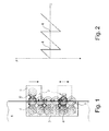
- An inventive beverage dispenser 1 which may be formed, for example, as a coffee machine, a height-adjustable beverage outlet 2, according to the Fig. 1 drawn with a solid line in an upper position and with broken line drawn in a lower position.
- a magnetic locking device 3 is provided with at least two locking layers 4 according to the invention.
- the Fig. 1 has the locking device 3 according to the invention even a total of six locking layers 4.
- the locking positions 4 of magnets 5 which may be formed for example as a permanent magnet or as an electromagnet, and which are opposite to a arranged in the height-adjustable beverage outlet 2 magnet 5 'at a captured detent position 4.
- a magnet 5, 5 ' is provided, while drinks machine side only magnetizable materials, such as metals, are arranged at defined distances from each other, of course, the effect of two opposite and reverse polarized magnets. 5 , 5 'is significantly larger.
- the height-adjustable beverage outlet 2 is arranged on a movable carriage 6, which slides on or in a not shown and drink machine side guide rail.
- a defined distance is provided between the drinks machine side magnets 5, in which no magnetizable materials, so for example plastic, are present, so that a locking of the height-adjustable beverage outlet 2 between two adjacent locking layers 4 not possible is.
- the beverage outlet 2 can be adjusted in a mechanically simple manner along the respective locking positions 4, wherein the achievement of the respective locking position 4 is displayed in each case haptically. If, accordingly, the carriage 6 is displaced along the individual locking positions 4, the force of the magnetic field of the first locking position must first be overcome in order to move the carriage 6 out of its detent position to move. In a further adjustment of the magnet 5 'is attracted to the nearest magnet 5 and thereby reaches the next detent position.
- the magnetically operating locking device 3 With the magnetically operating locking device 3 according to the invention, a sense of the user can be caused to see a qualitatively very high-quality asset compared. This feeling can additionally be reinforced by, for example, providing a damping device, not shown, which dampens the adjustment movement of the beverage outlet 2.
- Another great advantage of the magnetic detent device 3 according to the invention is that it does not have any mechanical parts subject to wear, such as latching lugs, and can thus operate over a long period of time without maintenance and wear.
- an adjustment of the beverage outlet 2 also no loud "clack" sound when taking a detent position 4, which is often perceived as disturbing in mechanical locking devices.
- Fig. 2 is a force-displacement diagram shown, which represents the adjustment of the height-adjustable beverage outlet 2, that is, the carriage 6, along the individual locking layers 4.
Landscapes
- Engineering & Computer Science (AREA)
- Food Science & Technology (AREA)
- Vending Machines For Individual Products (AREA)
- Control Of Vending Devices And Auxiliary Devices For Vending Devices (AREA)
- Apparatus For Making Beverages (AREA)
Abstract
Description
- Die vorliegende Erfindung betrifft einen Getränkeautomaten, insbesondere einen Kaffeeautomaten, mit einem höhenverstellbaren Getränkeauslauf gemäß dem Oberbegriff des Anspruchs 1.
- Ein derartiger Getränkeautomat mit einem höhenverstellbaren Auslauf ist beispielsweise aus der
DE 20 2004 020 916 U1 bekannt, ebenso wie aus derDE 200 17 859 U1 . Beiden Getränkeautomaten ist dabei gemein, einen Getränkeauslauf einfach an unterschiedlich große Getränkegefäße, wie beispielsweise Gläser oder Tassen, anpassen zu können. Die Höhenverstellung des Getränkeauslaufs ist dabei auch von Vorteil, wenn es darum geht, Verunreinigungen im Befüllbereich des Getränkebehälters zu vermeiden, wie diese beispielsweise bei einem zu hoch montierten statischen Getränkeauslauf beim Befüllen einer kleinen Espressotasse auftreten können. Da der Getränkeauslauf üblicherweise ein Eigengewicht aufweist, muss ein Haltemechanismus so stark sein, dass der Getränkeauslauf nicht von alleine nach unten rutschen kann. Hierfür können beispielsweise mechanische Rastvorrichtungen verwendet werden, die ein eigenmächtiges Herabrutschen vermeiden. Derartige mechanische Rastvorrichtungen sind jedoch konstruktiv aufwändig und erzeugen beim Verstellen des höhenverstellbaren Getränkeauslaufs ein unangenehmes Geräusch. - Die vorliegende Erfindung beschäftigt sich mit dem Problem, für einen Getränkeautomaten der gattungsgemäßen Art, eine verbesserte oder eine alternative Ausführungsform anzugeben, mit welcher insbesondere die Kundenzufriedenheit gesteigert werden kann.
- Dieses Problem wird erfindungsgemäß durch den Gegenstand des unabhängigen Anspruchs 1 gelöst. Vorteilhafte Ausführungsformen sind Gegenstand der abhängigen Ansprüche.
- Die vorliegende Erfindung beruht auf dem allgemeinen Gedanken, zur Höheneinstellung eines Getränkeauslaufes an einem Getränkeautomaten eine magnetische Rastvorrichtung mit zumindest zwei unterschiedlichen Rastlagen zu verwenden. Bei einer derartigen magnetisch arbeitenden Rastvorrichtung wird eine jeweilige, den Getränkeauslauf fixierende Haltekraft, über Magnetfelder realisiert, deren Magnetkräfte beim Verstellen des höhenverstellbaren Getränkeauslaufs zunächst überwunden werden müssen. Im Gegensatz zu einer mechanisch arbeitenden Rastvorrichtung, vermittelt eine derartige magnetische Rastvorrichtung ein Gefühl der Wertigkeit und trägt somit wesentlich zu einer gesteigerten Kundenzufriedenheit bei. Darüber hinaus weist die magnetische Rastvorrichtung keinerlei mechanisch ineinander greifende Teile auf, die üblicherweise einer Abnutzung unterliegen. Aus diesem Grund kann mit der magnetischen Rastvorrichtung eine nahezu wartungsfreie Verstell-/Arretiermöglichkeit für den höhenverstellbaren Getränkeauslauf geschaffen werden. Darüber hinaus ist durch eine entsprechende Wahl der Größe der magnetischen Feldkräfte eine Verstell- bzw. Haltekraft nahezu frei wählbar. Gleichzeitig kann die Reibung mit der erfindungsgemäßen magnetischen Rastvorrichtung reduziert und dadurch ein relativ leichtgängiges Verstellen des Getränkeauslaufs ermöglicht werden. Von wesentlichem Vorteil dürfte darüber hinaus sein, dass bei einem Verstellen des Getränkeauslaufs zwischen zwei Rastlagen kein störendes mechanisches Klappergeräusch auftritt, wodurch dem Benutzer stets das Gefühl eines besonders hochwertigen Wirtschaftsgutes vermittelt wird.
- Bei einer vorteilhaften Weiterbildung der erfindungsgemäßen Lösung, ist der höhenverstellbare Getränkeauslauf auf einem beweglichen Schlitten angeordnet, der an oder in einer getränkeautomatseitigen Führungsschiene gleitet, wobei an dem beweglichen Schlitten zumindest ein Magnet angeordnet ist, welcher mit an der Führungsschiene angeordneten Magneten oder magnetisierbaren Materialien zusammenwirkt. Denkbar ist hierbei, dass in dem Schlitten ein Permanentmagnet angeordnet ist, welcher mit in der Führungsschiene angeordneten Magneten oder magnetisierbaren Materialien zusammenwirkt. Durch die Wahl eines Abstandes zwischen den einzelnen an der Führungsschiene angeordneten Magneten bzw. magnetisierbaren Materialien, können unterschiedliche Rastlagen frei definiert werden. Um dabei einen Verstellvorgang zwischen zwei Rastlagen haptisch gut anzuzeigen, sind zwischen den jeweils an der Führungsschiene angeordneten Magneten oder magnetisierbaren Materialien üblicherweise keine magnetischen Materialien angeordnet, wodurch in diesem Bereich die Reibungskraft zusätzlich reduziert werden kann.
- Bei einer weiteren vorteilhaften Ausführungsform der erfindungsgemäßen Lösung, ist eine Dämpfereinrichtung zur Dämpfung der Verstellbewegung des Getränkeauslaufs vorgesehen. Eine derartige Dämpfereinrichtung verstärkt zusätzlich das von einem Nutzer empfundene Gefühl, sich einem qualitativ besonders hochwertigen Wirtschaftsgut gegenüber zu sehen. Derartige Dämpfereinrichtungen wurden zu Qualitätssteigerungszwecken erstmals Mitte der 80-iger Jahre in Kassettenrekordern eingesetzt, um eine Aufklappbewegung eines Kassettenfachdeckels zu dämpfen. Dabei war ein Einsatz zunächst nur in hochpreisigen Geräten geplant, wobei jedoch der Kundenwunsch nach einem breiten Einsatz derartiger Dämpfereinrichtungen auch bei vergleichsweise günstigen Kassettenrekordern dazu führte, dass innerhalb weniger Jahre nahezu sämtliche sich am Markt befindlichen Kassettenrekorder mit einer derartigen Dämpfereinrichtung ausgestattet wurden. Der Grund für das Kundenverlangen war hierbei ebenfalls das subjektive Empfinden, sich aufgrund der gedämpften Öffnungsbewegung des Kassettenfachdeckels einem qualitativ besonders hochwertigen Wirtschaftsgut gegenüber zu sehen.
- Weitere wichtige Merkmale und Vorteile der Erfindung ergeben sich aus den Unteransprüchen, aus den Zeichnungen und aus der zugehörigen Figurenbeschreibung anhand der Zeichnungen.
- Es versteht sich, dass die vorstehend genannten und die nachstehend noch zu erläuternden Merkmale nicht nur in der jeweils angegebenen Kombination, sondern auch in anderen Kombinationen oder in Alleinstellung verwendbar sind, ohne den Rahmen der vorliegenden Erfindung zu verlassen.
- Bevorzugte Ausführungsbeispiele der Erfindung sind in den Zeichnungen dargestellt und werden in der nachfolgenden Beschreibung näher erläutert, wobei sich gleiche Bezugszeichen auf gleiche oder ähnliche oder funktional gleiche Bauteile beziehen.
- Dabei zeigen, jeweils schematisch,
- Fig. 1
- eine Prinzipdarstellung einer erfindungsgemäß an einem höhenverstellbaren Getränkeauslauf eingesetzten magnetischen Rastvorrichtung,
- Fig. 2
- ein Kraft-Weg-Diagramm der in der
Fig. 1 dargestellten magnetischen Rastvorrichtung. - Entsprechend der
Fig. 1 , weist ein erfindungsgemäßer Getränkeautomat 1, welcher beispielsweise als Kaffeevollautomat ausgebildet sein kann, einen höhenverstellbaren Getränkeauslauf 2 dar, der gemäß derFig. 1 mit durchgezogener Linie in einer oberen Position und mit unterbrochen gezeichneter Linie in einer weiter unten gelegenen Position gezeichnet ist. Um dabei eine Höhenverstellung des höhenverstellbaren Getränkeauslasses 2 einerseits manuell möglichst einfach realisieren zu können, andererseits jedoch eine zuverlässige Fixierung des Getränkeauslasses 2 in unterschiedlichen Höhenlagen erreichen zu können, ist erfindungsgemäß eine magnetische Rastvorrichtung 3 mit zumindest zwei Rastlagen 4 vorgesehen. Gemäß derFig. 1 weist die erfindungsgemäße Rastvorrichtung 3 sogar insgesamt sechs Rastlagen 4 auf. Bestimmt werden dabei die Rastlagen 4 von Magneten 5, welche beispielsweise als Permanentmagneten oder als Elektromagneten ausgebildet sein können, und welche einem in dem höhenverstellbaren Getränkeauslass 2 angeordneten Magneten 5' bei einer eingenommenen Rastlage 4 gegenüberliegen. - Selbstverständlich ist dabei auch denkbar, dass lediglich im höhenverstellbaren Getränkeauslass 2 ein Magnet 5, 5' vorgesehen ist, während getränkeautomatenseitig lediglich magnetisierbare Materialien, beispielsweise Metalle, in definierten Abständen zueinander angeordnet sind, wobei selbstverständlich die Wirkung bei zwei sich gegenüberliegenden und umgekehrt gepolten Magneten 5, 5' deutlich größer ist. Der höhenverstellbare Getränkeauslauf 2 ist dabei auf einem beweglichen Schlitten 6 angeordnet, der an oder in einer nicht gezeigten und getränkeautomatenseitigen Führungsschiene gleitet. Um eine jeweilige Position unterschiedlicher Rastlagen 4 definieren zu können, ist zwischen den getränkeautomatenseitigen Magneten 5 jeweils ein definierter Abstand vorgesehen, in welchem keine magnetisierbaren Materialien, also beispielsweise Kunststoff, vorliegen, so dass ein Verrasten des höhenverstellbaren Getränkeauslaufs 2 zwischen zwei benachbarten Rastlagen 4 nicht möglich ist.
- Mit der erfindungsgemäßen Rastvorrichtung 3 lässt sich der Getränkeauslauf 2 in mechanisch einfacher Weise entlang der jeweiligen Rastlagen 4 verstellen, wobei das Erreichen der jeweiligen Rastlage 4 jeweils haptisch angezeigt wird. Wird demnach der Schlitten 6 entlang den einzelnen Rastlagen 4 verschoben, so muss zunächst die Kraft des Magnetfeldes der ersten Rastlage überwunden werden, um den Schlitten 6 aus seiner Raststellung zu bewegen. Bei einem weiteren Verstellen wird der Magnet 5' vom nächstgelegenen Magneten 5 angezogen und dadurch die nächste Raststellung erreicht.
- Mit der erfindungsgemäß magnetisch arbeitenden Rastvorrichtung 3 kann ein Gefühl beim Benutzer hervorgerufen werden, sich einem qualitativ besonders hochwertigen Wirtschaftsgut gegenüber zu sehen. Dieses Gefühl kann zusätzlich dadurch verstärkt werden, dass beispielsweise eine nicht gezeigte Dämpfereinrichtung vorgesehen ist, die die Verstellbewegung des Getränkeauslaufs 2 dämpft. Ein weiterer großer Vorteil der erfindungsgemäßen magnetischen Rastvorrichtung 3 liegt darin, dass diese keinerlei einem Verschleiß unterliegende mechanische Teile, wie beispielsweise Rastnasen, aufweist und dadurch wartungs- und verschleißfrei über lange Zeit arbeiten kann. Darüber hinaus entsteht bei einem Verstellen des Getränkeauslaufs 2 auch kein lautes "Klack"-Geräusch beim Einnehmen einer Raststellung 4, was bei mechanischen Rastvorrichtungen oftmals als störend empfunden wird.
- Gemäß der
Fig. 2 ist ein Kraft-Weg-Diagramm dargestellt, welches die Verstellbewegung des höhenverstellbaren Getränkeauslaufes 2, das heißt des Schlittens 6, entlang den einzelnen Rastlagen 4 darstellt. -
- 1
- Getränkeautomat
- 2
- Getränkeauslauf
- 3
- Rastvorrichtung
- 4
- Rastlage
- 5
- Magnet
- 6
- Schlitten
Claims (7)
- Getränkeautomat (1), insbesondere ein Kaffeevollautomat, mit einem höhenverstellbaren Getränkeauslauf (2), dadurch gekennzeichnet, dass zur Höheneinstellung des Getränkeauslaufs (2) eine magnetische Rastvorrichtung (3) mit zumindest zwei Rastlagen (4) vorgesehen ist.
- Getränkeautomat nach Anspruch 1,
dadurch gekennzeichnet,
dass der höhenverstellbare Getränkeauslauf (2) auf einem beweglichen Schlitten (6) angeordnet ist, der an oder in einer getränkeautomatenseitigen Führungsschiene gleitet. - Getränkeautomat nach Anspruch 2,
dadurch gekennzeichnet,
dass an dem beweglichen Schlitten (6) zumindest ein Magnet (5') angeordnet ist, welcher mit an der Führungsschiene angeordneten Magneten (5) oder magnetisierbaren Materialien (5) zusammenwirkt, oder umgekehrt. - Getränkeautomat nach Anspruch 2 oder 3,
dadurch gekennzeichnet,
dass die an der Führungsschiene angeordneten Magneten (5) oder magnetisierbaren Materialien (5) in definierten Abständen zueinander angeordnet sind. - Getränkeautomat nach Anspruch 4,
dadurch gekennzeichnet,
dass in Verschieberichtung des Getränkeauslaufs (2) zwischen den an der Führungsschiene angeordneten Magneten (5) oder magnetisierbaren Materialien (5) nicht magnetische Materialien, wie beispielsweise Kunststoff, vorgesehen sind. - Getränkeautomat nach einem der Ansprüche 1 bis 5,
dadurch gekennzeichnet,
dass zumindest ein Magnet (5,5') als Elektromagnet oder als Permanentmagnet ausgebildet ist. - Getränkeautomat nach einem der Ansprüche 1 bis 6,
dadurch gekennzeichnet,
dass eine Dämpfereinrichtung zur Dämpfung der Verstellbewegung des Getränkeauslaufs (2) vorgesehen ist.
Applications Claiming Priority (1)
| Application Number | Priority Date | Filing Date | Title |
|---|---|---|---|
| DE200810043571 DE102008043571A1 (de) | 2008-11-07 | 2008-11-07 | Getränkeautomat |
Publications (2)
| Publication Number | Publication Date |
|---|---|
| EP2186455A1 true EP2186455A1 (de) | 2010-05-19 |
| EP2186455B1 EP2186455B1 (de) | 2013-04-10 |
Family
ID=41616921
Family Applications (1)
| Application Number | Title | Priority Date | Filing Date |
|---|---|---|---|
| EP20090173946 Active EP2186455B1 (de) | 2008-11-07 | 2009-10-23 | Getränkeautomat |
Country Status (2)
| Country | Link |
|---|---|
| EP (1) | EP2186455B1 (de) |
| DE (1) | DE102008043571A1 (de) |
Cited By (2)
| Publication number | Priority date | Publication date | Assignee | Title |
|---|---|---|---|---|
| WO2013104643A1 (en) * | 2012-01-13 | 2013-07-18 | Nestec S.A. | Beverage machine with a removable module |
| EP2792283A1 (de) * | 2013-04-18 | 2014-10-22 | BSH Bosch und Siemens Hausgeräte GmbH | Getränkeautomat |
Citations (3)
| Publication number | Priority date | Publication date | Assignee | Title |
|---|---|---|---|---|
| DE29810291U1 (de) | 1998-06-09 | 1998-09-17 | Eugster/Frismag Ag, Romanshorn | Getränkespender, insbesondere Kaffee- oder Espressomaschine, mit einer Auslaufvorrichtung |
| DE20017859U1 (de) | 2000-10-18 | 2002-02-28 | WMF Württembergische Metallwarenfabrik AG, 73312 Geislingen | Kaffeemaschine |
| DE202004020916U1 (de) | 2004-01-30 | 2006-04-13 | BSH Bosch und Siemens Hausgeräte GmbH | Kaffeemaschine mit höhenverstellbarem Auslauf |
-
2008
- 2008-11-07 DE DE200810043571 patent/DE102008043571A1/de not_active Withdrawn
-
2009
- 2009-10-23 EP EP20090173946 patent/EP2186455B1/de active Active
Patent Citations (3)
| Publication number | Priority date | Publication date | Assignee | Title |
|---|---|---|---|---|
| DE29810291U1 (de) | 1998-06-09 | 1998-09-17 | Eugster/Frismag Ag, Romanshorn | Getränkespender, insbesondere Kaffee- oder Espressomaschine, mit einer Auslaufvorrichtung |
| DE20017859U1 (de) | 2000-10-18 | 2002-02-28 | WMF Württembergische Metallwarenfabrik AG, 73312 Geislingen | Kaffeemaschine |
| DE202004020916U1 (de) | 2004-01-30 | 2006-04-13 | BSH Bosch und Siemens Hausgeräte GmbH | Kaffeemaschine mit höhenverstellbarem Auslauf |
Cited By (3)
| Publication number | Priority date | Publication date | Assignee | Title |
|---|---|---|---|---|
| WO2013104643A1 (en) * | 2012-01-13 | 2013-07-18 | Nestec S.A. | Beverage machine with a removable module |
| CN104039206A (zh) * | 2012-01-13 | 2014-09-10 | 雀巢产品技术援助有限公司 | 具有可移除模块的饮料机 |
| EP2792283A1 (de) * | 2013-04-18 | 2014-10-22 | BSH Bosch und Siemens Hausgeräte GmbH | Getränkeautomat |
Also Published As
| Publication number | Publication date |
|---|---|
| EP2186455B1 (de) | 2013-04-10 |
| DE102008043571A1 (de) | 2010-05-12 |
Similar Documents
| Publication | Publication Date | Title |
|---|---|---|
| EP2770876B1 (de) | Synchronisierte verriegelung für ein bewegbares möbelteil | |
| EP3088646B1 (de) | Führungsvorrichtung für eine schiebetür | |
| DE102005012896B4 (de) | Fahrzeugsitz mit Kopfstütze | |
| EP3891351B1 (de) | Selbstjustierendes schliessstück für eine schliesseinheit | |
| EP2390448B1 (de) | Bidirektionale Einzugsvorrichtung für eine mittlere Schiebetür | |
| EP1874159B1 (de) | Dämpfungseinrichtung für bewegbare möbelteile | |
| DE202009013347U1 (de) | Selbsteinzugs- und Dämpfungsvorrichtung | |
| DE202014009636U1 (de) | Staufach für ein Fahrzeug und Fahrzeug mit dem Staufach | |
| EP2186455B1 (de) | Getränkeautomat | |
| EP3033464B1 (de) | Einrichtung mit einem "push-push"-mechanismus | |
| DE102013107562A1 (de) | Führungsvorrichtung für bewegbare Möbelteile | |
| DE2131120A1 (de) | Aus zwei Teilen bestehende teleskopische Vorrichtung | |
| WO2012123246A2 (de) | Kältegerät mit türen | |
| EP2781679B1 (de) | Beschleunigungs- und/oder Bremsvorrichtung | |
| EP2191753B1 (de) | Getränkeautomat | |
| DE102018104398A1 (de) | Möbel oder Haushaltsgerät und Verfahren zur Montage einer Funktionseinheit eines Schubelements in einem Möbel oder Haushaltsgerät | |
| EP2505744A2 (de) | Schließplatte für einen von einem Blendrahmen abstellbaren Fenster- oder Türflügel | |
| EP1649782B1 (de) | Ausziehführung | |
| DE102013211869A1 (de) | Verstellbare Ausgabeeinrichtung, insbesondere für eine Getränkemaschine | |
| EP4491838B1 (de) | Elektromagnetisches schloss und schliessfach | |
| DE10060655B4 (de) | Verschlußvorrichtung | |
| DE4327688A1 (de) | Auszugführung | |
| DE202013104627U1 (de) | Einrichtung zum Öffnen und Schließen eines Fachs | |
| EP3976916B1 (de) | Fahrzeugtürvorrichtung mit stromloser offenhaltefunktion | |
| EP3578737A1 (de) | Tür für ein haushaltsgerät mit einem zweiseitig an einem wandelement der tür bewegbar befestigten griff, sowie haushaltsgerät |
Legal Events
| Date | Code | Title | Description |
|---|---|---|---|
| PUAI | Public reference made under article 153(3) epc to a published international application that has entered the european phase |
Free format text: ORIGINAL CODE: 0009012 |
|
| AK | Designated contracting states |
Kind code of ref document: A1 Designated state(s): AT BE BG CH CY CZ DE DK EE ES FI FR GB GR HR HU IE IS IT LI LT LU LV MC MK MT NL NO PL PT RO SE SI SK SM TR |
|
| AX | Request for extension of the european patent |
Extension state: AL BA RS |
|
| 17P | Request for examination filed |
Effective date: 20101119 |
|
| 17Q | First examination report despatched |
Effective date: 20110126 |
|
| GRAP | Despatch of communication of intention to grant a patent |
Free format text: ORIGINAL CODE: EPIDOSNIGR1 |
|
| RIC1 | Information provided on ipc code assigned before grant |
Ipc: A47J 31/44 20060101AFI20121030BHEP |
|
| GRAS | Grant fee paid |
Free format text: ORIGINAL CODE: EPIDOSNIGR3 |
|
| GRAA | (expected) grant |
Free format text: ORIGINAL CODE: 0009210 |
|
| AK | Designated contracting states |
Kind code of ref document: B1 Designated state(s): AT BE BG CH CY CZ DE DK EE ES FI FR GB GR HR HU IE IS IT LI LT LU LV MC MK MT NL NO PL PT RO SE SI SK SM TR |
|
| REG | Reference to a national code |
Ref country code: GB Ref legal event code: FG4D Free format text: NOT ENGLISH |
|
| REG | Reference to a national code |
Ref country code: CH Ref legal event code: EP Ref country code: AT Ref legal event code: REF Ref document number: 605488 Country of ref document: AT Kind code of ref document: T Effective date: 20130415 |
|
| REG | Reference to a national code |
Ref country code: IE Ref legal event code: FG4D Free format text: LANGUAGE OF EP DOCUMENT: GERMAN |
|
| REG | Reference to a national code |
Ref country code: DE Ref legal event code: R096 Ref document number: 502009006792 Country of ref document: DE Effective date: 20130606 |
|
| PG25 | Lapsed in a contracting state [announced via postgrant information from national office to epo] |
Ref country code: SI Free format text: LAPSE BECAUSE OF FAILURE TO SUBMIT A TRANSLATION OF THE DESCRIPTION OR TO PAY THE FEE WITHIN THE PRESCRIBED TIME-LIMIT Effective date: 20130410 |
|
| REG | Reference to a national code |
Ref country code: LT Ref legal event code: MG4D Ref country code: NL Ref legal event code: VDEP Effective date: 20130410 |
|
| PG25 | Lapsed in a contracting state [announced via postgrant information from national office to epo] |
Ref country code: LT Free format text: LAPSE BECAUSE OF FAILURE TO SUBMIT A TRANSLATION OF THE DESCRIPTION OR TO PAY THE FEE WITHIN THE PRESCRIBED TIME-LIMIT Effective date: 20130410 Ref country code: NO Free format text: LAPSE BECAUSE OF FAILURE TO SUBMIT A TRANSLATION OF THE DESCRIPTION OR TO PAY THE FEE WITHIN THE PRESCRIBED TIME-LIMIT Effective date: 20130710 Ref country code: NL Free format text: LAPSE BECAUSE OF FAILURE TO SUBMIT A TRANSLATION OF THE DESCRIPTION OR TO PAY THE FEE WITHIN THE PRESCRIBED TIME-LIMIT Effective date: 20130410 Ref country code: IS Free format text: LAPSE BECAUSE OF FAILURE TO SUBMIT A TRANSLATION OF THE DESCRIPTION OR TO PAY THE FEE WITHIN THE PRESCRIBED TIME-LIMIT Effective date: 20130810 Ref country code: PT Free format text: LAPSE BECAUSE OF FAILURE TO SUBMIT A TRANSLATION OF THE DESCRIPTION OR TO PAY THE FEE WITHIN THE PRESCRIBED TIME-LIMIT Effective date: 20130812 Ref country code: ES Free format text: LAPSE BECAUSE OF FAILURE TO SUBMIT A TRANSLATION OF THE DESCRIPTION OR TO PAY THE FEE WITHIN THE PRESCRIBED TIME-LIMIT Effective date: 20130721 Ref country code: SE Free format text: LAPSE BECAUSE OF FAILURE TO SUBMIT A TRANSLATION OF THE DESCRIPTION OR TO PAY THE FEE WITHIN THE PRESCRIBED TIME-LIMIT Effective date: 20130410 Ref country code: FI Free format text: LAPSE BECAUSE OF FAILURE TO SUBMIT A TRANSLATION OF THE DESCRIPTION OR TO PAY THE FEE WITHIN THE PRESCRIBED TIME-LIMIT Effective date: 20130410 Ref country code: GR Free format text: LAPSE BECAUSE OF FAILURE TO SUBMIT A TRANSLATION OF THE DESCRIPTION OR TO PAY THE FEE WITHIN THE PRESCRIBED TIME-LIMIT Effective date: 20130711 |
|
| PG25 | Lapsed in a contracting state [announced via postgrant information from national office to epo] |
Ref country code: HR Free format text: LAPSE BECAUSE OF FAILURE TO SUBMIT A TRANSLATION OF THE DESCRIPTION OR TO PAY THE FEE WITHIN THE PRESCRIBED TIME-LIMIT Effective date: 20130410 Ref country code: PL Free format text: LAPSE BECAUSE OF FAILURE TO SUBMIT A TRANSLATION OF THE DESCRIPTION OR TO PAY THE FEE WITHIN THE PRESCRIBED TIME-LIMIT Effective date: 20130410 Ref country code: CY Free format text: LAPSE BECAUSE OF FAILURE TO SUBMIT A TRANSLATION OF THE DESCRIPTION OR TO PAY THE FEE WITHIN THE PRESCRIBED TIME-LIMIT Effective date: 20130410 Ref country code: LV Free format text: LAPSE BECAUSE OF FAILURE TO SUBMIT A TRANSLATION OF THE DESCRIPTION OR TO PAY THE FEE WITHIN THE PRESCRIBED TIME-LIMIT Effective date: 20130410 Ref country code: BG Free format text: LAPSE BECAUSE OF FAILURE TO SUBMIT A TRANSLATION OF THE DESCRIPTION OR TO PAY THE FEE WITHIN THE PRESCRIBED TIME-LIMIT Effective date: 20130710 |
|
| PG25 | Lapsed in a contracting state [announced via postgrant information from national office to epo] |
Ref country code: CZ Free format text: LAPSE BECAUSE OF FAILURE TO SUBMIT A TRANSLATION OF THE DESCRIPTION OR TO PAY THE FEE WITHIN THE PRESCRIBED TIME-LIMIT Effective date: 20130410 Ref country code: DK Free format text: LAPSE BECAUSE OF FAILURE TO SUBMIT A TRANSLATION OF THE DESCRIPTION OR TO PAY THE FEE WITHIN THE PRESCRIBED TIME-LIMIT Effective date: 20130410 Ref country code: EE Free format text: LAPSE BECAUSE OF FAILURE TO SUBMIT A TRANSLATION OF THE DESCRIPTION OR TO PAY THE FEE WITHIN THE PRESCRIBED TIME-LIMIT Effective date: 20130410 Ref country code: SK Free format text: LAPSE BECAUSE OF FAILURE TO SUBMIT A TRANSLATION OF THE DESCRIPTION OR TO PAY THE FEE WITHIN THE PRESCRIBED TIME-LIMIT Effective date: 20130410 |
|
| PLBE | No opposition filed within time limit |
Free format text: ORIGINAL CODE: 0009261 |
|
| STAA | Information on the status of an ep patent application or granted ep patent |
Free format text: STATUS: NO OPPOSITION FILED WITHIN TIME LIMIT |
|
| PG25 | Lapsed in a contracting state [announced via postgrant information from national office to epo] |
Ref country code: RO Free format text: LAPSE BECAUSE OF FAILURE TO SUBMIT A TRANSLATION OF THE DESCRIPTION OR TO PAY THE FEE WITHIN THE PRESCRIBED TIME-LIMIT Effective date: 20130410 Ref country code: IT Free format text: LAPSE BECAUSE OF FAILURE TO SUBMIT A TRANSLATION OF THE DESCRIPTION OR TO PAY THE FEE WITHIN THE PRESCRIBED TIME-LIMIT Effective date: 20130410 |
|
| 26N | No opposition filed |
Effective date: 20140113 |
|
| REG | Reference to a national code |
Ref country code: DE Ref legal event code: R097 Ref document number: 502009006792 Country of ref document: DE Effective date: 20140113 |
|
| BERE | Be: lapsed |
Owner name: BSH BOSCH UND SIEMENS HAUSGERATE G.M.B.H. Effective date: 20131031 |
|
| PG25 | Lapsed in a contracting state [announced via postgrant information from national office to epo] |
Ref country code: MC Free format text: LAPSE BECAUSE OF FAILURE TO SUBMIT A TRANSLATION OF THE DESCRIPTION OR TO PAY THE FEE WITHIN THE PRESCRIBED TIME-LIMIT Effective date: 20130410 |
|
| REG | Reference to a national code |
Ref country code: CH Ref legal event code: PL |
|
| REG | Reference to a national code |
Ref country code: IE Ref legal event code: MM4A |
|
| PG25 | Lapsed in a contracting state [announced via postgrant information from national office to epo] |
Ref country code: LI Free format text: LAPSE BECAUSE OF NON-PAYMENT OF DUE FEES Effective date: 20131031 Ref country code: CH Free format text: LAPSE BECAUSE OF NON-PAYMENT OF DUE FEES Effective date: 20131031 |
|
| PG25 | Lapsed in a contracting state [announced via postgrant information from national office to epo] |
Ref country code: BE Free format text: LAPSE BECAUSE OF NON-PAYMENT OF DUE FEES Effective date: 20131031 |
|
| PG25 | Lapsed in a contracting state [announced via postgrant information from national office to epo] |
Ref country code: IE Free format text: LAPSE BECAUSE OF NON-PAYMENT OF DUE FEES Effective date: 20131023 |
|
| REG | Reference to a national code |
Ref country code: DE Ref legal event code: R081 Ref document number: 502009006792 Country of ref document: DE Owner name: BSH HAUSGERAETE GMBH, DE Free format text: FORMER OWNER: BSH BOSCH UND SIEMENS HAUSGERAETE GMBH, 81739 MUENCHEN, DE Effective date: 20150409 |
|
| PG25 | Lapsed in a contracting state [announced via postgrant information from national office to epo] |
Ref country code: SM Free format text: LAPSE BECAUSE OF FAILURE TO SUBMIT A TRANSLATION OF THE DESCRIPTION OR TO PAY THE FEE WITHIN THE PRESCRIBED TIME-LIMIT Effective date: 20130410 |
|
| PG25 | Lapsed in a contracting state [announced via postgrant information from national office to epo] |
Ref country code: TR Free format text: LAPSE BECAUSE OF FAILURE TO SUBMIT A TRANSLATION OF THE DESCRIPTION OR TO PAY THE FEE WITHIN THE PRESCRIBED TIME-LIMIT Effective date: 20130410 |
|
| PG25 | Lapsed in a contracting state [announced via postgrant information from national office to epo] |
Ref country code: LU Free format text: LAPSE BECAUSE OF NON-PAYMENT OF DUE FEES Effective date: 20131023 Ref country code: MK Free format text: LAPSE BECAUSE OF FAILURE TO SUBMIT A TRANSLATION OF THE DESCRIPTION OR TO PAY THE FEE WITHIN THE PRESCRIBED TIME-LIMIT Effective date: 20130410 Ref country code: HU Free format text: LAPSE BECAUSE OF FAILURE TO SUBMIT A TRANSLATION OF THE DESCRIPTION OR TO PAY THE FEE WITHIN THE PRESCRIBED TIME-LIMIT; INVALID AB INITIO Effective date: 20091023 |
|
| PG25 | Lapsed in a contracting state [announced via postgrant information from national office to epo] |
Ref country code: MT Free format text: LAPSE BECAUSE OF FAILURE TO SUBMIT A TRANSLATION OF THE DESCRIPTION OR TO PAY THE FEE WITHIN THE PRESCRIBED TIME-LIMIT Effective date: 20130410 |
|
| REG | Reference to a national code |
Ref country code: FR Ref legal event code: PLFP Year of fee payment: 7 |
|
| REG | Reference to a national code |
Ref country code: FR Ref legal event code: CD Owner name: BSH HAUSGERATE GMBH, DE Effective date: 20151022 |
|
| REG | Reference to a national code |
Ref country code: AT Ref legal event code: MM01 Ref document number: 605488 Country of ref document: AT Kind code of ref document: T Effective date: 20141023 |
|
| PG25 | Lapsed in a contracting state [announced via postgrant information from national office to epo] |
Ref country code: AT Free format text: LAPSE BECAUSE OF NON-PAYMENT OF DUE FEES Effective date: 20141023 |
|
| REG | Reference to a national code |
Ref country code: FR Ref legal event code: PLFP Year of fee payment: 8 |
|
| REG | Reference to a national code |
Ref country code: FR Ref legal event code: PLFP Year of fee payment: 9 |
|
| REG | Reference to a national code |
Ref country code: FR Ref legal event code: PLFP Year of fee payment: 10 |
|
| PGFP | Annual fee paid to national office [announced via postgrant information from national office to epo] |
Ref country code: DE Payment date: 20251031 Year of fee payment: 17 |
|
| PGFP | Annual fee paid to national office [announced via postgrant information from national office to epo] |
Ref country code: GB Payment date: 20251024 Year of fee payment: 17 |
|
| PGFP | Annual fee paid to national office [announced via postgrant information from national office to epo] |
Ref country code: FR Payment date: 20251024 Year of fee payment: 17 |