EP2185451B1 - Vorrichtung zum fördern von bögen - Google Patents
Vorrichtung zum fördern von bögen Download PDFInfo
- Publication number
- EP2185451B1 EP2185451B1 EP08794148.0A EP08794148A EP2185451B1 EP 2185451 B1 EP2185451 B1 EP 2185451B1 EP 08794148 A EP08794148 A EP 08794148A EP 2185451 B1 EP2185451 B1 EP 2185451B1
- Authority
- EP
- European Patent Office
- Prior art keywords
- sheet
- sheets
- lifting means
- arrangement
- movement
- Prior art date
- Legal status (The legal status is an assumption and is not a legal conclusion. Google has not performed a legal analysis and makes no representation as to the accuracy of the status listed.)
- Active
Links
Images

Classifications
-
- B—PERFORMING OPERATIONS; TRANSPORTING
- B65—CONVEYING; PACKING; STORING; HANDLING THIN OR FILAMENTARY MATERIAL
- B65H—HANDLING THIN OR FILAMENTARY MATERIAL, e.g. SHEETS, WEBS, CABLES
- B65H29/00—Delivering or advancing articles from machines; Advancing articles to or into piles
- B65H29/66—Advancing articles in overlapping streams
- B65H29/6609—Advancing articles in overlapping streams forming an overlapping stream
- B65H29/6618—Advancing articles in overlapping streams forming an overlapping stream upon transfer from a first conveyor to a second conveyor advancing at slower speed
- B65H29/6627—Advancing articles in overlapping streams forming an overlapping stream upon transfer from a first conveyor to a second conveyor advancing at slower speed in combination with auxiliary means for overlapping articles
-
- B—PERFORMING OPERATIONS; TRANSPORTING
- B65—CONVEYING; PACKING; STORING; HANDLING THIN OR FILAMENTARY MATERIAL
- B65H—HANDLING THIN OR FILAMENTARY MATERIAL, e.g. SHEETS, WEBS, CABLES
- B65H29/00—Delivering or advancing articles from machines; Advancing articles to or into piles
- B65H29/66—Advancing articles in overlapping streams
-
- B—PERFORMING OPERATIONS; TRANSPORTING
- B65—CONVEYING; PACKING; STORING; HANDLING THIN OR FILAMENTARY MATERIAL
- B65H—HANDLING THIN OR FILAMENTARY MATERIAL, e.g. SHEETS, WEBS, CABLES
- B65H29/00—Delivering or advancing articles from machines; Advancing articles to or into piles
- B65H29/12—Delivering or advancing articles from machines; Advancing articles to or into piles by means of the nip between two, or between two sets of, moving tapes or bands or rollers
- B65H29/14—Delivering or advancing articles from machines; Advancing articles to or into piles by means of the nip between two, or between two sets of, moving tapes or bands or rollers and introducing into a pile
-
- B—PERFORMING OPERATIONS; TRANSPORTING
- B65—CONVEYING; PACKING; STORING; HANDLING THIN OR FILAMENTARY MATERIAL
- B65H—HANDLING THIN OR FILAMENTARY MATERIAL, e.g. SHEETS, WEBS, CABLES
- B65H29/00—Delivering or advancing articles from machines; Advancing articles to or into piles
- B65H29/68—Reducing the speed of articles as they advance
-
- B—PERFORMING OPERATIONS; TRANSPORTING
- B65—CONVEYING; PACKING; STORING; HANDLING THIN OR FILAMENTARY MATERIAL
- B65H—HANDLING THIN OR FILAMENTARY MATERIAL, e.g. SHEETS, WEBS, CABLES
- B65H29/00—Delivering or advancing articles from machines; Advancing articles to or into piles
- B65H29/70—Article bending or stiffening arrangements
-
- B—PERFORMING OPERATIONS; TRANSPORTING
- B65—CONVEYING; PACKING; STORING; HANDLING THIN OR FILAMENTARY MATERIAL
- B65H—HANDLING THIN OR FILAMENTARY MATERIAL, e.g. SHEETS, WEBS, CABLES
- B65H31/00—Pile receivers
- B65H31/04—Pile receivers with movable end support arranged to recede as pile accumulates
- B65H31/08—Pile receivers with movable end support arranged to recede as pile accumulates the articles being piled one above another
- B65H31/10—Pile receivers with movable end support arranged to recede as pile accumulates the articles being piled one above another and applied at the top of the pile
-
- B—PERFORMING OPERATIONS; TRANSPORTING
- B65—CONVEYING; PACKING; STORING; HANDLING THIN OR FILAMENTARY MATERIAL
- B65H—HANDLING THIN OR FILAMENTARY MATERIAL, e.g. SHEETS, WEBS, CABLES
- B65H31/00—Pile receivers
- B65H31/30—Arrangements for removing completed piles
- B65H31/3054—Arrangements for removing completed piles by moving the surface supporting the lowermost article of the pile, e.g. by using belts or rollers
-
- B—PERFORMING OPERATIONS; TRANSPORTING
- B65—CONVEYING; PACKING; STORING; HANDLING THIN OR FILAMENTARY MATERIAL
- B65H—HANDLING THIN OR FILAMENTARY MATERIAL, e.g. SHEETS, WEBS, CABLES
- B65H31/00—Pile receivers
- B65H31/34—Apparatus for squaring-up piled articles
- B65H31/36—Auxiliary devices for contacting each article with a front stop as it is piled
-
- B—PERFORMING OPERATIONS; TRANSPORTING
- B65—CONVEYING; PACKING; STORING; HANDLING THIN OR FILAMENTARY MATERIAL
- B65H—HANDLING THIN OR FILAMENTARY MATERIAL, e.g. SHEETS, WEBS, CABLES
- B65H2301/00—Handling processes for sheets or webs
- B65H2301/50—Auxiliary process performed during handling process
- B65H2301/51—Modifying a characteristic of handled material
- B65H2301/512—Changing form of handled material
- B65H2301/5121—Bending, buckling, curling, bringing a curvature
- B65H2301/51214—Bending, buckling, curling, bringing a curvature parallel to direction of displacement of handled material
-
- B—PERFORMING OPERATIONS; TRANSPORTING
- B65—CONVEYING; PACKING; STORING; HANDLING THIN OR FILAMENTARY MATERIAL
- B65H—HANDLING THIN OR FILAMENTARY MATERIAL, e.g. SHEETS, WEBS, CABLES
- B65H2404/00—Parts for transporting or guiding the handled material
- B65H2404/60—Other elements in face contact with handled material
- B65H2404/69—Other means designated for special purpose
- B65H2404/694—Non driven means for pressing the handled material on forwarding or guiding elements
- B65H2404/6942—Non driven means for pressing the handled material on forwarding or guiding elements in sliding contact with handled material
Definitions
- the present invention relates to an arrangement for conveying of sheets through said arrangement according to the preamble of claim 1.
- Such arrangements are commonly used, for example, in post-treatment equipment in paper printing.
- sheets for stacking in and to a pile are traditionally connected to one another and wound on a reel.
- the sheets in the form of a continuous web, are conveyed into a cutting device which cuts them to a suitable size for individual sheets.
- the sheets are conveyed to a stacking arrangement which makes it possible for them to be stacked on one another in a single process.
- the stacking arrangement is so arranged that the sheets are first placed mutually in line on a conveyor belt which carries them to a stacking region.
- the sheets are placed on the conveyor belt such that a rear edge of each sheet is overlapped by a front edge of a following sheet. Having the sheets thus mutually overlapping makes it possible for them to be stacked on one another without becoming jammed. This is because each following sheet slides over, and will thus be placed on top of, the sheet preceding it.
- EP-0192211-A2 refers to an arrangement in which sheets are placed on a conveyor belt.
- the sheets in EP-0192211-A2 are placed on the conveyor belt such that a rear edge of each sheet is overlapped by a front edge of a following sheet.
- a problem with EP-0192211-A2 is that it cannot handle thin sheets which are not stiff enough. If a sheet is too thin or not stiff enough, the result in EP-0192211-A2 is that when a sheet has to be moved from the conveyor belt to the arrangement for the formation of a stack of sheets, the front edge of the sheet will deflect downwards at the transition between the conveyor belt and the stack, with the result that the sheet is damaged and the stacking process has to be interrupted.
- British patent specification GB-985227 refers to variants of an arrangement comprising a downpresser which presses down the rear edge of a sheet which is being transferred from a conveyor belt to another conveyor belt which moves at a slower speed.
- the fact that the downpresser pushes the rear edge down makes it possible for the front edge of a following sheet to overlap the pressed-down rear edge of the preceding sheet.
- the downpresser is movable and rotatable. Such a movable element runs quite a large risk of disintegrating, thereby possibly resulting in the whole arrangement disintegrating.
- a further problem with the downpresser is that it may leave impressions in the sheet pressed down.
- a problem with the inventions according to EP-019221 1-A2 and GB-985227 is that they are not configured to be able to handle thin sheets but only so-called normal sheets, e.g. sheets with paper thickness corresponding to usual traditional writing paper. This means that sheets thinner than such writing paper which are used in the inventions according to EP-019221 1-A2 and GB-985227 will become jammed, with consequent interruption of the sheet stacking processes.
- GB-783976 describes a sheet cutting and laying apparatus where sheets are conveyed and corrugated by action of an upper roll and a lower roll, the upper roll having forming discs that interact with the lower roll that has a wave-like profile.
- An object of the present invention is to provide an arrangement in which the aforesaid problems are eliminated.
- a further object of the present invention is to provide an arrangement which can convey sheets on a conveyor belt on which they are placed such that a rear edge of each sheet is overlapped by a front edge of a following sheet.
- a further object of the present invention is to provide an arrangement in which a front edge of each sheet is stiffened in its running direction.
- a further object of the present invention is to provide an arrangement which can cope with conveying and handling of paper which is curved through having been stored in a reel of continuous paper sheet.
- a further object of the present invention is to provide an arrangement in which the reliability of sheet conveying is improved relative to the state of the art.
- a further object of the present invention is to provide an arrangement which is cost- effective as compared with the state of the art and is easy to construct, making it possible to optimize both cost and time.
- An advantage achieved with an arrangement according to the characterizing part of claim 1 is that it makes it possible to convey and stack thin sheets at a high speed.
- the need to use sheets which are as thin as possible has arisen because thin sheets not only occupy less space but are also less expensive.
- Another reason for wishing to use thinner sheets is that a reel can accommodate more of them than a reel of traditional sheets of normal thickness.
- the lifting means comprises a number of grooves extending in the direction of movement in a surface of the lifting means, which surface said sheets pass over and the grooves in the lifting means are so configured that the upper belt element, by its configuration, fits in the grooves.
- the lifting means acts upon the front edge in a forward portion of the sheet, as viewed in a section through said forward portion of the sheet and transversely to the direction of movement of the sheet, by the sheet being conveyed over the lifting means, whereby the front edge and the sheet assume a wavy shape comprising a number of ridges and valleys which are parallel with the direction of movement, thereby stiffening the sheet in said direction of movement.
- Said ridges and valleys serve as a beam element in the sheet.
- the stiffening contributes to the front edge of the sheet, after passing over the lifting means, partly maintaining its shape in the sheet movement direction by the front edge partly following parallel with and in direct proximity to the upper belt element of the lower belt portion until the belt elements mutually coincide in the same direction of movement.
- the grooves in the surface of the lifting means are deeper on the side of the lifting means which faces away from the receiving rolls than the grooves in the portion of the surface of the lifting means which is closer to the receiving rolls.
- the grooves are disposed vertically below the respective belt elements which extend above said lifting means, and the latter comprises at least as many grooves as the number of belt elements.
- the upper belt element is acted upon by part of said belt elements moving closer to the lifting means.
- the grooves provided in the lifting means make it possible for the respective belt elements approaching the lifting means to fit into the respective grooves.
- the sheet When a sheet is conveyed between the lifting means and the belt element, the sheet is thus partly pressed down by the belt element into the respective grooves and thereby assumes a stiffening wavy shape in the sheet movement direction.
- a further advantage is that the belt element is not caused to slide over an edge portion of the lifting means and thereby be subject to wear due to friction between it and the lifting means.
- the adjustable roll When the adjustable roll is moved in the sheet movement direction, said portion of the belt element is acted upon such that the upper belt element is instead moved upwards and away from said grooves, thereby creating an intermediate space between the lifting means and the upper belt element.
- the lifting means is an elongate means with a length corresponding to at least the width of a sheet which passes between the receiving rolls, which lifting means is situated parallel to said receiving rolls.
- the surface of the lifting means, which surface said sheet passes over, is adjustable in that the lifting means can be adjusted in the height direction and be rotated about an axis through the lifting means.
- the lifting means is fixed in a specified position.
- the surface is angled relative to the sheet movement direction such that when a sheet passes between the receiving rolls, its front edge meets, after the receiving rolls, said surface of the lifting means.
- a perpendicular in the surface has a main direction towards the upper receiving roll. This means that the front edge of the sheet can be brought into a partly upward path over the lifting means after passing between the receiving rolls.
- the arrangement comprises an adjustable roll situated in the sheet movement direction after, and parallel to, the receiving rolls such that the lifting means, as viewed in the movement direction, is situated between the upper receiving roll and the adjustable roll.
- the position of the lifting means between the receiving roll and the adjustable roll prevents the front edge of sheets passing through arrangement, between and past the receiving rolls, from deflecting downwards after the receiving rolls and thereby becoming jammed in the arrangement.
- part of the upper belt element extends partly in a first span and partly in a second span, which first span extends from an underside on the upper receiving roll to an underside on the adjustable roll, which second span extends in the movement direction from the underside on the adjustable roll to an underside on an end roll, which first and second spans jointly form, at the point where they meet on the underside of the adjustable roll, an angle of less than 180° upwards towards the upper belt element. Said angle between the first and second spans becomes smaller upon movement of the adjustable roll in a parallel direction towards the receiving rolls.
- the first span imparts to a sheet which passes between the receiving rolls a stiffening front edge as a result of the first span of the belt element pressing the sheet down into the grooves of the lifting means, whereupon the sheet assumes the previously mentioned wavy shape.
- the second span ensures that the sheet continues its movement over an underlying sheet preceding it through the arrangement.
- the lifting means acts upon the rear edge of a sheet passing over the lifting means such that said rear edge, after passing over and past the lifting means, is caused to move towards the receiving surface at a speed higher than the speed which the receiving surface has in its movement in a direction away from the receiving rolls.
- the lifting means is situated at a level above the level of the receiving surface. This means that the rear edge of the sheet drops towards said receiving surface under the action of gravity.
- the receiving surface is a continuous belt means which has an upper portion parallel with part of the upper belt element, which upper portion of the belt means and said part of the upper belt element both run in the same direction of movement but said part of the upper belt element moves at a speed higher than the speed at which said portion of the belt means moves.
- the upper belt element has contact with a sheet passing through the arrangement when the sheet passes between the receiving rolls, as a result of the sheet having contact with the first span of the belt element.
- the belt element changes to the second span the sheet ceases to be in contact with the belt element. This is because the second span of the belt element runs at a level above sheets situated on the receiving surface.
- the receiving surface causes the sheets to move at a slower speed.
- the movement of each sheet in the direction of movement, after passing over and past the lifting means, is reduced by the front edge of the sheet reaching a braking wheel at which the respective sheet is placed on top of a preceding sheet such that the respective front edge of adjacent sheets on the receiving surface overlaps the rear edge of a preceding sheet on the receiving surface.
- the braking wheel causes overlapping sheets placed in line on the receiving surface to have a constant or predetermined distance between the respective front edges of the successive overlapping sheets in the row.
- each sheet in the direction of movement is halted by the front edge of the sheet reaching a stop membrane, whereupon the respective sheet is placed on top of a preceding sheet in a stack on the receiving surface.
- the receiving surface moves downwards such that a vertical stack of sheets is created on the receiving surface.
- the receiving surface imparts a vertical movement to sheets by its downward movement in response to each further sheet being placed on it, whereby a stack of sheets is created on the receiving surface.
- Fig. 1 depicts part of an arrangement (1) in the form of an active portion of the arrangement (1) for making it possible to convey sheets, preferably thin sheets, through the arrangement (1).
- the arrangement according to Fig. 1 has an upper receiving roll (3), a lower receiving roll (4), an upper belt element (5), a receiving surface (6) and a lifting means (10).
- the upper belt element (5) takes the form of a number of bands extending partly in an oval path above the receiving surface (6) and partly round the upper receiving roll (3). Sheets passing through the arrangement (not depicted in Fig. 1 ) are conveyed with a direction of movement (7) between and past the receiving rolls (3, 4).
- the lifting means (10) is situated after the receiving rolls (3, 4) in the direction of movement (7).
- the lifting means (10) comprises in an upper surface a number of grooves (13) which are parallel to the direction of movement (7). Each groove (13) is disposed vertically below a band of the belt element (5). This means that there are in the lifting means (10) at least as many grooves (13) as there are bands (5).
- the belt element also extends round an adjustable roll (14) disposed in the direction of movement (7) at a distance from and after the lifting means (10) and the receiving rolls (3, 4).
- Fig. 1 shows the belt element (5) extending in a first span (15) from the underside of the upper receiving roll (3) to the underside on the adjustable roll (14). It also shows the belt element (5) extending in a second span (16) from the underside on the adjustable roll (14) in the direction of movement (7) towards an end roll (17) disposed on the arrangement (depicted in Figs. 3 and 4 ).
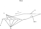
- Fig. 2 depicts a sheet (2a, b) comprising sides, a rear edge (8) and a front edge (9) and shows how it has been acted upon/shaped by being passed through the arrangement (1), between and past the receiving rolls (3, 4) and between the belt element (5) and the lifting means (10).
- the belt element (5) acts upon a sheet such that it partly presses the front edge (9) of the sheet (2a, b) down into the grooves (13).
- the grooves (13) thus shape the sheet (2a, b) in the direction of movement so that it assumes a shape comprising a number of ridges (11) and valleys (12).
- ridges (11) and valleys (12) extend in the direction of movement (7) in the sheet (2a, b), they serve as beam elements in the latter whereby it is stiffened in the direction of movement (7).
- Said stiffening has the effect that a sheet (2a, b), preferably a thin sheet, does not deflect immediately after passing between and past the receiving rolls (3, 4) and that its front edge (9) will therefore land on the receiving surface (6) instead.
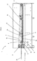
- Fig. 3 depicts an embodiment of the invention for placing sheets mutually in line in an overlapping sequence.
- the embodiment of the arrangement (1) according to Fig. 3 comprises the elements which are necessary in the sheet handling process.
- sheets (2a, b) enter the arrangement (1) from the left side when the arrangement (1) is viewed from in front.
- a first sheet (2a) has been conveyed between an upper receiving roll (3) and a lower receiving roll (4) in the direction from left to right in and through the arrangement (1).
- the sheet (2a) runs over a lifting means (10).
- the sheets (2a, b) are conveyed in the direction of movement (7) which in Fig.
- the lifting means (10) is situated, as viewed in the direction of movement (7), after said upper and lower receiving rolls (3, 4).
- the receiving surface takes with advantage the form of a number of bands.
- An upper belt element (5) extends in direct proximity to and partly above the lifting means (10).
- the upper belt element (5) and the outer roll surface of the upper and lower receiving rolls (3, 4) run at the same speed.
- the upper belt element (5) helps to move the sheet (2a, b), after the receiving rolls (3, 4), over and past the lifting means (10).
- the speed of the sheet (2a, b) is altered by its movement being reduced. This is because the receiving surface (6) moves at a slower speed than the upper belt element (5).
- the upper belt element (5) is situated above the lower belt element/receiving surface (6) at a distance such that the speed of the sheet (2a, b) through the arrangement (1) is only affected by the receiving surface (6).
- Sheets (2a, b) passing through the arrangement position themselves such that a front edge (9) of a sheet (2b) is positioned overlapping a rear edge (8) of a previous sheet (2a) passing through the arrangement (1).
- the fact that the previous sheet (2a) when it is placed/lands on the receiving surface thereby reduces its speed makes it possible for the front edge (9) of a following second sheet (2b) travelling at a higher speed and at a higher level over and past the lifting means (10) to be placed on top of and overlap the rear edge (8) of the previous sheet (2a).
- each sheet (2a, b) is stiffened by being formed between the lifting means (10) and the upper belt element (5) so that the sheet assumes a shape with ridges (11) and valleys (12) which serve as stiffening beam elements in the respective sheet (2a, b).
- This stiffening of the front edge (9) enables the sheet (2a, b) to travel so far past and above the rear edge (8) of a preceding and previous sheet (2a) so that the front edge (9) of the second sheet (2b) is placed/lands on top of and past the rear edge (8) of the previous sheet (2a).
- the upper belt element (5) and the receiving surface (6) according to the embodiment in Fig. 3 constitute a continuous band running in an oval path.
- the upper belt element (5) extends between and partly round the upper receiving roll (3) and partly round an end roll (17).
- An adjustable roll (14) is enclosed by said belt element (5) in its oval span round said receiving roll (3) and end roll (17).
- Said rolls (3, 14, 17) are connected via their respective end portions to a frame portion.
- the upper belt element (5) has a lower portion extending partly in a first span (15) from a first underside on the upper receiving roll (3) to a second underside on the adjustable roll (14) and partly in a second span (16) from the second underside on the adjustable roll (14) to a third underside on the end roll (17). From an upper side on the end roll (17) the upper portion of the upper belt element (5) extends to an upper side on the upper receiving roll (3).
- the first span (15) and the second span (16) of the belt element (5) meet at a point situated on said second underside of the adjustable roll (14). At their mutual meeting point said first and second spans (15, 16) form an angle (18) depicted in the diagram as an angle arc. This angle (18) is open upwards.
- the second span (16) is parallel with the receiving surface (6).
- the adjustable roll (14) is connected via its respective end portions to a movement device which is itself movably connected to the respective frame portion.
- the upper receiving roll (3) is situated at a higher level than the adjustable roll (14) and the end roll (17) relative to a horizontal plane through the second span (16) forming part of the belt element (5). This means that movement of the adjustable roll (14) towards the upper receiving roll (3) will bring the first span (15) closer, and at a sharper angle, to the lifting means (10) while at the same time the angle between said first and second spans (15, 16) becomes smaller.
- the arrangement (1) comprises a braking wheel (21), see Fig. 3 .
- the braking wheel (21) causes overlapping sheets (2a, b) placed mutually in line on the receiving surface (6) to have a constant or predetermined distance between the respective front edges (9) of the successive overlapping sheets (2a, b) in the row.
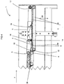
- Fig. 4 depicts an embodiment of the invention in which sheets are placed in an overlapping sequence to form a stack of sheets.
- the sheets (2a, b) are conveyed through the arrangement (1), between and past the receiving rolls (3, 4) and over the lifting means (10) before landing on the receiving surface (6).
- the receiving surface (6) can move both downwards and upwards (20).
- a stop element (19) is disposed on the arrangement (1) according to the embodiment of the invention in Fig. 4 .
- the purpose of the stop element (19) is to prevent sheets from continuing to slide over and past a preceding and underlying sheet on the receiving surface (6).
- the result is mutual stacking of the sheets (2a, b) in a stack while at the same time the receiving surface (6) and the sheets (2a, b) move downwards.
- the sheets are conveyed away from the arrangement (1) by the receiving surface (6) comprising a number of bands which convey the stack away from it.
Landscapes
- Engineering & Computer Science (AREA)
- Mechanical Engineering (AREA)
- Delivering By Means Of Belts And Rollers (AREA)
- Pile Receivers (AREA)
- Separation, Sorting, Adjustment, Or Bending Of Sheets To Be Conveyed (AREA)
Claims (12)
- Vorrichtung (1) zum Fördern von Bögen (2a, b), eine solche Vorrichtung (1) umfassend eine obere Aufnahmewalze (3), eine untere Aufnahmewalze (4), zumindest ein oberes Bandelement (5) und eine Aufnahmefläche (6), wobei das obere Bandelement (5) sich in einen Bereich über der Aufnahmefläche (6) erstreckt, wobei die Bögen (2a, b) in einer im Wesentlichen horizontalen Bewegungsrichtung (7) in Richtung der Aufnahmewalzen (3, 4) gefördert werden, wobei die Aufnahmewalzen (3, 4) während der Rotation die Bögen (2a, b) einen nach dem anderen zwischen und an den Aufnahmewalzen (3, 4) vorbei bewegen, woraufhin die entsprechenden Bögen (2a, b) nach dem Passieren durch und zwischen den Aufnahmewalzen (3, 4) zwischen der Aufnahmefläche (6) und dem oberen Bandelement (5) angeordnet sind, wobei die Bögen (2a, b) zwischen dem oberen Bandelement (5) und der Aufnahmefläche (6) übereinander angeordnet sind, sodass eine Hinterkante (8) eines Bogens (2a), die auf der Aufnahmefläche (6) angeordnet ist, von einer Vorderkante (9) eines nachfolgenden Bogens (2b) überlappt wird, wobei sich eine Hebeeinrichtung (10) in der Bewegungsrichtung (7) der Bögen hinter den Aufnahmewalzen (3, 4) befindet und ausgebildet ist, zum Einwirken auf die Bögen (2a, b), die die Aufnahmewalzen (3, 4) durchlaufen und sich über die Hebeeinrichtung bewegen, sodass die Vorderkante (9) eines Bogens (2b), der sich über und an der Hebeeinrichtung (10) vorbei bewegt hat, eine Form annimmt, die dieses in der Bewegungsrichtung (7) des Bogens stärkt, wobei die Hebeeinrichtung (10) eine Anzahl von Rillen (13) umfasst, die sich in der Bewegungsrichtung (7) der Bögen in einer Oberfläche der Hebeeinrichtung (10) erstrecken, wobei die Bögen (2 a, b) sich über die Oberfläche hinweg bewegen, dadurch gekennzeichnet, dass die Rillen (13) in der Hebeeinrichtung (10) so ausgebildet sind, dass das obere Bandelement (5) durch seine Ausbildung in die Rillen (13) passt.
- Vorrichtung (1) zum Fördern von Bögen (2a, b) nach Anspruch 1, dadurch gekennzeichnet, dass die Hebeeinrichtung (10) auf die Vorderkante (9), in einem vorderen Bereich des Bogens (2a, b), wenn in einem Schnitt durch den vorderen Bereich des Bogens (2a, b) und quer zu der Bewegungsrichtung (7) des Bogens (2a, b) betrachtet, des über die Hebereinrichtung geförderten Bogens (2a, b) einwirkt, sodass die Vorderkante (9) und der Bogen (2a, b) eine gewellte Form annehmen, die eine Anzahl von Erhebungen (11) und Vertiefungen (12) umfasst, wobei die Erhebungen (11) und Vertiefungen (12) parallel zu der Bewegungsrichtung (7) ausgebildet sind, und der Bogen (2a, b) somit in der Bewegungsrichtung (7) gestärkt wird.
- Vorrichtung (1) zum Fördern von Bögen (2a, b) nach Anspruch 1-2, dadurch gekennzeichnet, dass die Rillen (13) in der Hebeeinrichtung (10) vertikal unter dem entsprechenden Band des oberen Bandelements (5), welches sich über der Hebeeinrichtung (10) erstreckt, angeordnet sind, wobei die Hebeeinrichtung zumindest so viele Rillen (13) umfasst, wie die Anzahl der Bänder des oberen Bandelements (5).
- Vorrichtung (1) zum Fördern von Bögen (2a, b) nach Anspruch 1-3, dadurch gekennzeichnet, dass die Hebeeinrichtung (10) eine längliche Einrichtung ist mit einer Länge, die zumindest der Breite des Bogens (2a, b), der zwischen den Aufnahmewalzen (3, 4) hindurchläuft, entspricht, wobei die Hebeeinrichtung (10) parallel zu den Aufnahmewalzen (3, 4) angeordnet ist.
- Vorrichtung (1) zum Fördern von Bögen (2a, b) nach Anspruch 1-4, dadurch gekennzeichnet, dass die Oberfläche der Hebeeinrichtung (10), welches die Oberfläche ist, über die sich die Bögen (2a, b) hinwegbewegen, von der Hebeeinrichtung (10) in der Höhe verstellbar und drehbar um eine Achse durch die Hebeeinrichtung (10) ist.
- Vorrichtung (1) zum Fördern von Bögen (2a, b) nach Anspruch 1-5, dadurch gekennzeichnet, dass die Vorrichtung eine verstellbare Walze (14) umfasst, die in der Bewegungsrichtung (7) des Bogens (2a, b) hinter und parallel zu den Aufnahmewalzen (3, 4) beabstandet angeordnet ist, sodass die Hebeeinrichtung (10), wenn aus der Bewegungsrichtung (7) betrachtet, zwischen der oberen Aufnahmewalze (3) und der verstellbaren Walze (14) angeordnet ist.
- Vorrichtung (1) zum Fördern von Bögen (2a, b) nach Anspruch 6, dadurch gekennzeichnet, dass ein Teil des oberen Bandelements (5) sich teilweise über eine erste Spanne (15) und teilweise über eine zweite Spanne (16) erstreckt, wobei sich die erste Spanne (15) von einer Unterseite der oberen Aufnahmewalze (3) zu einer Unterseite der verstellbaren Walze erstreckt, wobei die zweite Spanne (16) sich in der Bewegungsrichtung (7) von der Unterseite der verstellbaren Walze (14) zu einer Unterseite einer Endwalze (17) erstreckt, wobei die erste Spanne (15) und die zweite Spanne (16) zusammen an ihrem Treffpunkt an der Unterseite der verstellbaren Walze (14) einen Winkel (18) von weniger als 180° aufwärts in Richtung des oberen Bandelements (5) bilden.
- Vorrichtung (1) zum Fördern von Bögen (2a, b) nach Anspruch 7, dadurch gekennzeichnet, dass der Winkel (18) zwischen der ersten und der zweiten Spanne (15, 16) kleiner wird, bei einer Bewegung der verstellbaren Walze (14) parallel in Richtung der Aufnahmewalzen (3, 4).
- Vorrichtung (1) zum Fördern von Bögen (2a, b) nach Anspruch 1-8, dadurch gekennzeichnet, dass die Aufnahmefläche (6) ein kontinuierliches Gurtmittel ist, das einen oberen Abschnitt aufweist, der parallel zu einem Teil des oberen Bandelements (5) ist, wobei der obere Abschnitt des Gurtmittels und der Teil des oberen Bandelements (5) in der gleichen Bewegungsrichtung verlaufen, wobei der Teil des oberen Bandelements (5) sich mit einer Geschwindigkeit bewegt, die größer ist, als die Geschwindigkeit, mit der sich der Abschnitt des Gurtmittels bewegt.
- Vorrichtung (1) zum Fördern von Bögen (2a, b) nach Anspruch 1-9, dadurch gekennzeichnet, dass die Geschwindigkeit der Bewegung jedes Bogens (2a, b) in der Bewegungsrichtung (7) nach dem Passieren über und vorbei an der Hebeeinrichtung (10) von der Vorderkante (9) des Bogens, das ein Bremsrad (21) erreicht, verringert wird, woraufhin der entsprechende Bogen (2a, b) auf einem vorherigen Bogen (2a, b) platziert wird, sodass die entsprechende Vorderkante (9) benachbarter Bögen (2a, b) auf der Aufnahmefläche (6) die Hinterkante (8) eines vorherigen Bogens auf der Aufnahmefläche (6) überlappt.
- Vorrichtung (1) zum Fördern von Bögen (2a, b) nach Anspruch 1-8, dadurch gekennzeichnet, dass die Bewegung jedes Bogens (2a, b) in der Bewegungsrichtung (7) nach dem Passieren über und vorbei an der Hebeeinrichtung (10) gestoppt wird von der Vorderkante (9) eines Bogens, der eine Stoppmembran (19) erreicht, woraufhin der entsprechende Bogen (2a, b) auf einem vorherigen Bogen (2a, b) in einem Stapel auf der Aufnahmefläche (6) platziert wird.
- Vorrichtung (1) zum Fördern von Bögen (2a, b) nach Anspruch 1-8 und 11, dadurch gekennzeichnet, dass jedes Mal, wenn ein Bogen (2a, b) auf der Aufnahmefläche (6) platziert wird, die Letztere eine Abwärtsbewegung (20) ausführt, sodass ein vertikaler Stapel von Bögen (2a, b) auf der Aufnahmefläche (6) geschaffen wird.
Applications Claiming Priority (2)
| Application Number | Priority Date | Filing Date | Title |
|---|---|---|---|
| SE0701892A SE531201C2 (sv) | 2007-08-20 | 2007-08-20 | Anordning för stapling av ark |
| PCT/SE2008/050923 WO2009025612A1 (en) | 2007-08-20 | 2008-08-14 | Arrangement for stacking sheets |
Publications (3)
| Publication Number | Publication Date |
|---|---|
| EP2185451A1 EP2185451A1 (de) | 2010-05-19 |
| EP2185451A4 EP2185451A4 (de) | 2014-12-03 |
| EP2185451B1 true EP2185451B1 (de) | 2016-06-01 |
Family
ID=40210399
Family Applications (1)
| Application Number | Title | Priority Date | Filing Date |
|---|---|---|---|
| EP08794148.0A Active EP2185451B1 (de) | 2007-08-20 | 2008-08-14 | Vorrichtung zum fördern von bögen |
Country Status (5)
| Country | Link |
|---|---|
| US (1) | US8141869B2 (de) |
| EP (1) | EP2185451B1 (de) |
| JP (1) | JP2010536685A (de) |
| SE (1) | SE531201C2 (de) |
| WO (1) | WO2009025612A1 (de) |
Families Citing this family (5)
| Publication number | Priority date | Publication date | Assignee | Title |
|---|---|---|---|---|
| WO2013112150A1 (en) | 2012-01-26 | 2013-08-01 | Hewlett-Packard Development Company, L.P. | Media stacker to receive media sheets from a system |
| IT201800010574A1 (it) * | 2018-11-26 | 2020-05-26 | Tecnau Srl | Equipaggiamento di accumulazione per fogli di differenti dimensioni |
| IT201800010572A1 (it) * | 2018-11-26 | 2020-05-26 | Tecnau Srl | Equipaggiamento di accumulazione fogli |
| IT202100016238A1 (it) | 2021-06-21 | 2022-12-21 | Tecnau Srl | Equipaggiamento per impilamento ad alta velocità di fogli cartacei |
| IT202100016211A1 (it) | 2021-06-21 | 2022-12-21 | Tecnau Srl | Equipaggiamento per impilamento fogli |
Citations (1)
| Publication number | Priority date | Publication date | Assignee | Title |
|---|---|---|---|---|
| US20060056953A1 (en) * | 2004-09-10 | 2006-03-16 | Pitney Bowes Incorporated | High throughput sheet accumulator |
Family Cites Families (27)
| Publication number | Priority date | Publication date | Assignee | Title |
|---|---|---|---|---|
| US2261972A (en) * | 1940-04-27 | 1941-11-11 | Maxson Automatic Mach | Sheet feeding and stacking method and machine |
| GB783976A (en) * | 1954-11-17 | 1957-10-02 | Masson Scott & Company Ltd | Improvements in and relating to sheet cutting and laying machines or apparatus |
| FI42666B (de) | 1961-06-02 | 1970-06-01 | Jagenberg Werke Ag | |
| GB1086460A (en) | 1964-07-30 | 1967-10-11 | Jagenberg Werke Ag | Apparatus for conveying and stacking paper sheets |
| DE1245703B (de) | 1964-10-23 | 1967-07-27 | Jagenberg Werke Ag | Verfahren und Vorrichtung zum Einlegen von Kennstreifen in den Bogenstapel eines Querschneiders |
| US4157177A (en) * | 1975-12-10 | 1979-06-05 | Dr. Otto C. Strecker Kg. | Apparatus for converting a stream of partly overlapping sheets into a stack |
| US4346881A (en) * | 1979-04-12 | 1982-08-31 | Lenox Machine Company, Inc. | Method of and means for handling paper sheets to be stacked |
| US4313669A (en) * | 1980-10-27 | 1982-02-02 | Pako Corporation | Photographic print stacking tray |
| JPS6011677B2 (ja) * | 1980-11-29 | 1985-03-27 | 小森印刷機械株式会社 | 輪転印刷機の排紙装置 |
| CH652840A5 (de) * | 1981-08-11 | 1985-11-29 | Grapha Holding Ag | Vorrichtung zum zaehlen der druckbogen eines schuppenstromes. |
| US4538801A (en) * | 1982-06-09 | 1985-09-03 | Therm-O-Type Corporation | Paper sheet handling mechanism |
| US4652197A (en) | 1985-02-22 | 1987-03-24 | Littleton Industrial Consultants, Inc. | Sheet counter and stacker system |
| US4898570A (en) * | 1987-09-14 | 1990-02-06 | Pitney Bowes | Method and apparatus for half folding paper sheets |
| DE8903802U1 (de) * | 1989-03-28 | 1989-06-08 | Heidelberger Druckmaschinen Ag, 6900 Heidelberg | Bogenausleger an Rotationsdruckmaschinen |
| DE3940960A1 (de) * | 1989-12-12 | 1991-07-11 | Jagenberg Ag | Verfahren und vorrichtung zum abbremsen von auf einen stapel abzulegenden boegen, insbesondere papier- oder kartonboegen |
| JP2558509Y2 (ja) * | 1992-05-19 | 1997-12-24 | 理想科学工業株式会社 | 排紙台 |
| US5192068A (en) * | 1992-05-28 | 1993-03-09 | Xerox Corporation | Sheet feeding and separating apparatus with an improved entrance guide |
| FR2693179B1 (fr) * | 1992-07-03 | 1994-10-14 | Martin Sa | Organe de retenue de feuilles pour un magasin d'empilage. |
| DE4305579A1 (de) * | 1993-02-24 | 1994-08-25 | Will E C H Gmbh & Co | Vorrichtung zum Ansammeln von Papierbogen |
| US5671920A (en) * | 1995-06-01 | 1997-09-30 | Xerox Corporation | High speed printed sheet stacking and registration system |
| US5909873A (en) * | 1997-06-03 | 1999-06-08 | Littleton Industrial Consultants, Inc. | Non marking slow down apparatus |
| US6022017A (en) | 1998-06-02 | 2000-02-08 | Marquip, Inc. | Method for handling a small gap order change in a corrugator |
| DE19850901A1 (de) * | 1998-11-05 | 2000-05-11 | Will E C H Gmbh & Co | Vorrichtung zum Transport von einander zu überlappenden Bögen, insbesondere Papierbögen |
| DE19851371A1 (de) * | 1998-11-07 | 2000-05-11 | Bielomatik Leuze & Co | Vorrichtung zum Schaffen einer Lücke in einem geschuppten Bogenstrom |
| US20050082745A1 (en) * | 2003-06-05 | 2005-04-21 | Williams Robert M. | Inline stacker with non-interrupt gap generator and integrated drive control and jam response |
| JP4957408B2 (ja) * | 2007-06-28 | 2012-06-20 | ブラザー工業株式会社 | シート排出装置及び画像形成装置 |
| US7913999B2 (en) * | 2008-06-12 | 2011-03-29 | Xerox Corporation | Resilient belt sheet compiler with mixed sheet length mode |
-
2007
- 2007-08-20 SE SE0701892A patent/SE531201C2/sv unknown
-
2008
- 2008-08-14 JP JP2010521813A patent/JP2010536685A/ja active Pending
- 2008-08-14 US US12/733,254 patent/US8141869B2/en active Active
- 2008-08-14 EP EP08794148.0A patent/EP2185451B1/de active Active
- 2008-08-14 WO PCT/SE2008/050923 patent/WO2009025612A1/en not_active Ceased
Patent Citations (1)
| Publication number | Priority date | Publication date | Assignee | Title |
|---|---|---|---|---|
| US20060056953A1 (en) * | 2004-09-10 | 2006-03-16 | Pitney Bowes Incorporated | High throughput sheet accumulator |
Also Published As
| Publication number | Publication date |
|---|---|
| US20100283197A1 (en) | 2010-11-11 |
| US8141869B2 (en) | 2012-03-27 |
| SE0701892L (sv) | 2009-01-13 |
| JP2010536685A (ja) | 2010-12-02 |
| WO2009025612A1 (en) | 2009-02-26 |
| SE531201C2 (sv) | 2009-01-13 |
| EP2185451A4 (de) | 2014-12-03 |
| EP2185451A1 (de) | 2010-05-19 |
Similar Documents
| Publication | Publication Date | Title |
|---|---|---|
| US8141869B2 (en) | Arrangement for stacking sheets | |
| US7918443B2 (en) | Under-shingled article handling and stacking system and method | |
| EP1223107B1 (de) | Vorrichtung zum Entladen von geordneten Gruppen von Papierrollen | |
| NL7908767A (nl) | Werkwijze en inrichting voor het stapelen van plano's. | |
| EP4341189B1 (de) | System und verfahren zum stapeln einer gefächerten, durchgehenden bahn aus blattmaterial | |
| GB2078687A (en) | Apparatus for holding down sheets in a stack | |
| US9567178B2 (en) | Device and method for producing packages of stacked materials | |
| US4815924A (en) | Sheet stacking means after a cross-cutting saw | |
| JP4196192B2 (ja) | スタッカーバンドラー及びその制御方法 | |
| DE19616047A1 (de) | Zusammentragmaschine | |
| US5765483A (en) | Device for automatic format adjustment in a delivery of a rotary printing press | |
| US3433476A (en) | Apparatus for elimination of sheets in cross cutting and similar machines | |
| EP1661837B1 (de) | Bogenausgabesystem | |
| US4691604A (en) | Anti-jamming die | |
| US6318954B1 (en) | Device for stacking sheets, in particular sheet-fed paper or cardboard sheets delivered onto pallets | |
| US20020060412A1 (en) | Sheet understacking feeding mechanism | |
| US6155559A (en) | Delivery system for flat products | |
| US20080149755A1 (en) | Device for Uninterrupted Winding of a Continuously-Fed Textile Material Web | |
| US20050175440A1 (en) | Device for stacking sheets, especially sheets of paper or cardboard transported by a stream feeder, onto pallets | |
| US7871071B2 (en) | Grouping device | |
| US4354674A (en) | Device for distributing flexible sheets in collecting bins | |
| JP7671234B2 (ja) | 片面段ボールシート用シートスタッカ | |
| JP4703914B2 (ja) | シート整列装置 | |
| EP2421683B1 (de) | Querschneidgruppe | |
| US20040145108A1 (en) | Flyless stream shingling and stream merging apparatus and method |
Legal Events
| Date | Code | Title | Description |
|---|---|---|---|
| PUAI | Public reference made under article 153(3) epc to a published international application that has entered the european phase |
Free format text: ORIGINAL CODE: 0009012 |
|
| 17P | Request for examination filed |
Effective date: 20100319 |
|
| AK | Designated contracting states |
Kind code of ref document: A1 Designated state(s): AT BE BG CH CY CZ DE DK EE ES FI FR GB GR HR HU IE IS IT LI LT LU LV MC MT NL NO PL PT RO SE SI SK TR |
|
| AX | Request for extension of the european patent |
Extension state: AL BA MK RS |
|
| RIN1 | Information on inventor provided before grant (corrected) |
Inventor name: PERSSON, JAN-ERIK Inventor name: BENJAMINSSON, PETER |
|
| DAX | Request for extension of the european patent (deleted) | ||
| A4 | Supplementary search report drawn up and despatched |
Effective date: 20141031 |
|
| RIC1 | Information provided on ipc code assigned before grant |
Ipc: B65H 29/68 20060101ALI20141027BHEP Ipc: B65H 29/70 20060101AFI20141027BHEP Ipc: B65H 31/06 20060101ALI20141027BHEP Ipc: B65H 31/36 20060101ALI20141027BHEP Ipc: B65H 29/66 20060101ALI20141027BHEP |
|
| 17Q | First examination report despatched |
Effective date: 20150410 |
|
| GRAP | Despatch of communication of intention to grant a patent |
Free format text: ORIGINAL CODE: EPIDOSNIGR1 |
|
| INTG | Intention to grant announced |
Effective date: 20150828 |
|
| RAP1 | Party data changed (applicant data changed or rights of an application transferred) |
Owner name: TECNAU AB |
|
| RIC1 | Information provided on ipc code assigned before grant |
Ipc: B65H 31/06 20060101ALI20151210BHEP Ipc: B65H 31/36 20060101ALI20151210BHEP Ipc: B65H 29/70 20060101AFI20151210BHEP Ipc: B65H 29/66 20060101ALI20151210BHEP Ipc: B65H 29/68 20060101ALI20151210BHEP Ipc: B65H 31/30 20060101ALI20151210BHEP |
|
| INTG | Intention to grant announced |
Effective date: 20151223 |
|
| GRAS | Grant fee paid |
Free format text: ORIGINAL CODE: EPIDOSNIGR3 |
|
| GRAA | (expected) grant |
Free format text: ORIGINAL CODE: 0009210 |
|
| AK | Designated contracting states |
Kind code of ref document: B1 Designated state(s): AT BE BG CH CY CZ DE DK EE ES FI FR GB GR HR HU IE IS IT LI LT LU LV MC MT NL NO PL PT RO SE SI SK TR |
|
| REG | Reference to a national code |
Ref country code: GB Ref legal event code: FG4D |
|
| REG | Reference to a national code |
Ref country code: CH Ref legal event code: EP Ref country code: AT Ref legal event code: REF Ref document number: 803758 Country of ref document: AT Kind code of ref document: T Effective date: 20160615 |
|
| REG | Reference to a national code |
Ref country code: IE Ref legal event code: FG4D |
|
| REG | Reference to a national code |
Ref country code: DE Ref legal event code: R096 Ref document number: 602008044541 Country of ref document: DE |
|
| REG | Reference to a national code |
Ref country code: FR Ref legal event code: PLFP Year of fee payment: 9 |
|
| REG | Reference to a national code |
Ref country code: LT Ref legal event code: MG4D |
|
| REG | Reference to a national code |
Ref country code: NL Ref legal event code: MP Effective date: 20160601 |
|
| PG25 | Lapsed in a contracting state [announced via postgrant information from national office to epo] |
Ref country code: LT Free format text: LAPSE BECAUSE OF FAILURE TO SUBMIT A TRANSLATION OF THE DESCRIPTION OR TO PAY THE FEE WITHIN THE PRESCRIBED TIME-LIMIT Effective date: 20160601 Ref country code: NO Free format text: LAPSE BECAUSE OF FAILURE TO SUBMIT A TRANSLATION OF THE DESCRIPTION OR TO PAY THE FEE WITHIN THE PRESCRIBED TIME-LIMIT Effective date: 20160901 Ref country code: FI Free format text: LAPSE BECAUSE OF FAILURE TO SUBMIT A TRANSLATION OF THE DESCRIPTION OR TO PAY THE FEE WITHIN THE PRESCRIBED TIME-LIMIT Effective date: 20160601 |
|
| REG | Reference to a national code |
Ref country code: AT Ref legal event code: MK05 Ref document number: 803758 Country of ref document: AT Kind code of ref document: T Effective date: 20160601 |
|
| PG25 | Lapsed in a contracting state [announced via postgrant information from national office to epo] |
Ref country code: HR Free format text: LAPSE BECAUSE OF FAILURE TO SUBMIT A TRANSLATION OF THE DESCRIPTION OR TO PAY THE FEE WITHIN THE PRESCRIBED TIME-LIMIT Effective date: 20160601 Ref country code: GR Free format text: LAPSE BECAUSE OF FAILURE TO SUBMIT A TRANSLATION OF THE DESCRIPTION OR TO PAY THE FEE WITHIN THE PRESCRIBED TIME-LIMIT Effective date: 20160902 Ref country code: LV Free format text: LAPSE BECAUSE OF FAILURE TO SUBMIT A TRANSLATION OF THE DESCRIPTION OR TO PAY THE FEE WITHIN THE PRESCRIBED TIME-LIMIT Effective date: 20160601 Ref country code: NL Free format text: LAPSE BECAUSE OF FAILURE TO SUBMIT A TRANSLATION OF THE DESCRIPTION OR TO PAY THE FEE WITHIN THE PRESCRIBED TIME-LIMIT Effective date: 20160601 Ref country code: ES Free format text: LAPSE BECAUSE OF FAILURE TO SUBMIT A TRANSLATION OF THE DESCRIPTION OR TO PAY THE FEE WITHIN THE PRESCRIBED TIME-LIMIT Effective date: 20160601 Ref country code: SE Free format text: LAPSE BECAUSE OF FAILURE TO SUBMIT A TRANSLATION OF THE DESCRIPTION OR TO PAY THE FEE WITHIN THE PRESCRIBED TIME-LIMIT Effective date: 20160601 |
|
| PG25 | Lapsed in a contracting state [announced via postgrant information from national office to epo] |
Ref country code: BE Free format text: LAPSE BECAUSE OF NON-PAYMENT OF DUE FEES Effective date: 20160831 |
|
| PG25 | Lapsed in a contracting state [announced via postgrant information from national office to epo] |
Ref country code: CZ Free format text: LAPSE BECAUSE OF FAILURE TO SUBMIT A TRANSLATION OF THE DESCRIPTION OR TO PAY THE FEE WITHIN THE PRESCRIBED TIME-LIMIT Effective date: 20160601 Ref country code: SK Free format text: LAPSE BECAUSE OF FAILURE TO SUBMIT A TRANSLATION OF THE DESCRIPTION OR TO PAY THE FEE WITHIN THE PRESCRIBED TIME-LIMIT Effective date: 20160601 Ref country code: EE Free format text: LAPSE BECAUSE OF FAILURE TO SUBMIT A TRANSLATION OF THE DESCRIPTION OR TO PAY THE FEE WITHIN THE PRESCRIBED TIME-LIMIT Effective date: 20160601 Ref country code: RO Free format text: LAPSE BECAUSE OF FAILURE TO SUBMIT A TRANSLATION OF THE DESCRIPTION OR TO PAY THE FEE WITHIN THE PRESCRIBED TIME-LIMIT Effective date: 20160601 Ref country code: IS Free format text: LAPSE BECAUSE OF FAILURE TO SUBMIT A TRANSLATION OF THE DESCRIPTION OR TO PAY THE FEE WITHIN THE PRESCRIBED TIME-LIMIT Effective date: 20161001 |
|
| PG25 | Lapsed in a contracting state [announced via postgrant information from national office to epo] |
Ref country code: BE Free format text: LAPSE BECAUSE OF FAILURE TO SUBMIT A TRANSLATION OF THE DESCRIPTION OR TO PAY THE FEE WITHIN THE PRESCRIBED TIME-LIMIT Effective date: 20160601 Ref country code: AT Free format text: LAPSE BECAUSE OF FAILURE TO SUBMIT A TRANSLATION OF THE DESCRIPTION OR TO PAY THE FEE WITHIN THE PRESCRIBED TIME-LIMIT Effective date: 20160601 Ref country code: PL Free format text: LAPSE BECAUSE OF FAILURE TO SUBMIT A TRANSLATION OF THE DESCRIPTION OR TO PAY THE FEE WITHIN THE PRESCRIBED TIME-LIMIT Effective date: 20160601 Ref country code: PT Free format text: LAPSE BECAUSE OF FAILURE TO SUBMIT A TRANSLATION OF THE DESCRIPTION OR TO PAY THE FEE WITHIN THE PRESCRIBED TIME-LIMIT Effective date: 20161003 |
|
| REG | Reference to a national code |
Ref country code: DE Ref legal event code: R097 Ref document number: 602008044541 Country of ref document: DE |
|
| PG25 | Lapsed in a contracting state [announced via postgrant information from national office to epo] |
Ref country code: MC Free format text: LAPSE BECAUSE OF FAILURE TO SUBMIT A TRANSLATION OF THE DESCRIPTION OR TO PAY THE FEE WITHIN THE PRESCRIBED TIME-LIMIT Effective date: 20160601 |
|
| REG | Reference to a national code |
Ref country code: CH Ref legal event code: PL |
|
| PLBE | No opposition filed within time limit |
Free format text: ORIGINAL CODE: 0009261 |
|
| STAA | Information on the status of an ep patent application or granted ep patent |
Free format text: STATUS: NO OPPOSITION FILED WITHIN TIME LIMIT |
|
| PG25 | Lapsed in a contracting state [announced via postgrant information from national office to epo] |
Ref country code: CH Free format text: LAPSE BECAUSE OF NON-PAYMENT OF DUE FEES Effective date: 20160831 Ref country code: LI Free format text: LAPSE BECAUSE OF NON-PAYMENT OF DUE FEES Effective date: 20160831 |
|
| 26N | No opposition filed |
Effective date: 20170302 |
|
| PG25 | Lapsed in a contracting state [announced via postgrant information from national office to epo] |
Ref country code: DK Free format text: LAPSE BECAUSE OF FAILURE TO SUBMIT A TRANSLATION OF THE DESCRIPTION OR TO PAY THE FEE WITHIN THE PRESCRIBED TIME-LIMIT Effective date: 20160601 Ref country code: SI Free format text: LAPSE BECAUSE OF FAILURE TO SUBMIT A TRANSLATION OF THE DESCRIPTION OR TO PAY THE FEE WITHIN THE PRESCRIBED TIME-LIMIT Effective date: 20160601 |
|
| REG | Reference to a national code |
Ref country code: IE Ref legal event code: MM4A |
|
| PG25 | Lapsed in a contracting state [announced via postgrant information from national office to epo] |
Ref country code: IE Free format text: LAPSE BECAUSE OF NON-PAYMENT OF DUE FEES Effective date: 20160814 |
|
| REG | Reference to a national code |
Ref country code: FR Ref legal event code: PLFP Year of fee payment: 10 |
|
| PG25 | Lapsed in a contracting state [announced via postgrant information from national office to epo] |
Ref country code: LU Free format text: LAPSE BECAUSE OF NON-PAYMENT OF DUE FEES Effective date: 20160814 |
|
| PG25 | Lapsed in a contracting state [announced via postgrant information from national office to epo] |
Ref country code: HU Free format text: LAPSE BECAUSE OF FAILURE TO SUBMIT A TRANSLATION OF THE DESCRIPTION OR TO PAY THE FEE WITHIN THE PRESCRIBED TIME-LIMIT; INVALID AB INITIO Effective date: 20080814 Ref country code: CY Free format text: LAPSE BECAUSE OF FAILURE TO SUBMIT A TRANSLATION OF THE DESCRIPTION OR TO PAY THE FEE WITHIN THE PRESCRIBED TIME-LIMIT Effective date: 20160601 |
|
| PG25 | Lapsed in a contracting state [announced via postgrant information from national office to epo] |
Ref country code: MT Free format text: LAPSE BECAUSE OF NON-PAYMENT OF DUE FEES Effective date: 20160831 Ref country code: TR Free format text: LAPSE BECAUSE OF FAILURE TO SUBMIT A TRANSLATION OF THE DESCRIPTION OR TO PAY THE FEE WITHIN THE PRESCRIBED TIME-LIMIT Effective date: 20160601 |
|
| PG25 | Lapsed in a contracting state [announced via postgrant information from national office to epo] |
Ref country code: BG Free format text: LAPSE BECAUSE OF FAILURE TO SUBMIT A TRANSLATION OF THE DESCRIPTION OR TO PAY THE FEE WITHIN THE PRESCRIBED TIME-LIMIT Effective date: 20160601 |
|
| REG | Reference to a national code |
Ref country code: FR Ref legal event code: PLFP Year of fee payment: 11 |
|
| PGFP | Annual fee paid to national office [announced via postgrant information from national office to epo] |
Ref country code: DE Payment date: 20240802 Year of fee payment: 17 |
|
| PGFP | Annual fee paid to national office [announced via postgrant information from national office to epo] |
Ref country code: GB Payment date: 20240813 Year of fee payment: 17 |
|
| PGFP | Annual fee paid to national office [announced via postgrant information from national office to epo] |
Ref country code: FR Payment date: 20240820 Year of fee payment: 17 |
|
| PGFP | Annual fee paid to national office [announced via postgrant information from national office to epo] |
Ref country code: IT Payment date: 20240729 Year of fee payment: 17 |
|
| REG | Reference to a national code |
Ref country code: DE Ref legal event code: R119 Ref document number: 602008044541 Country of ref document: DE |
|
| GBPC | Gb: european patent ceased through non-payment of renewal fee |
Effective date: 20250814 |