EP2184838A1 - Axial gap type motor - Google Patents
Axial gap type motor Download PDFInfo
- Publication number
- EP2184838A1 EP2184838A1 EP08777992A EP08777992A EP2184838A1 EP 2184838 A1 EP2184838 A1 EP 2184838A1 EP 08777992 A EP08777992 A EP 08777992A EP 08777992 A EP08777992 A EP 08777992A EP 2184838 A1 EP2184838 A1 EP 2184838A1
- Authority
- EP
- European Patent Office
- Prior art keywords
- rotation axis
- rotor
- permanent magnet
- axial gap
- magnetic member
- Prior art date
- Legal status (The legal status is an assumption and is not a legal conclusion. Google has not performed a legal analysis and makes no representation as to the accuracy of the status listed.)
- Granted
Links
Images


Classifications
-
- H—ELECTRICITY
- H02—GENERATION; CONVERSION OR DISTRIBUTION OF ELECTRIC POWER
- H02K—DYNAMO-ELECTRIC MACHINES
- H02K1/00—Details of the magnetic circuit
- H02K1/06—Details of the magnetic circuit characterised by the shape, form or construction
- H02K1/22—Rotating parts of the magnetic circuit
- H02K1/27—Rotor cores with permanent magnets
- H02K1/2793—Rotors axially facing stators
- H02K1/2795—Rotors axially facing stators the rotor consisting of two or more circumferentially positioned magnets
- H02K1/2796—Rotors axially facing stators the rotor consisting of two or more circumferentially positioned magnets where both axial sides of the rotor face a stator
-
- H—ELECTRICITY
- H02—GENERATION; CONVERSION OR DISTRIBUTION OF ELECTRIC POWER
- H02K—DYNAMO-ELECTRIC MACHINES
- H02K21/00—Synchronous motors having permanent magnets; Synchronous generators having permanent magnets
- H02K21/12—Synchronous motors having permanent magnets; Synchronous generators having permanent magnets with stationary armatures and rotating magnets
- H02K21/24—Synchronous motors having permanent magnets; Synchronous generators having permanent magnets with stationary armatures and rotating magnets with magnets axially facing the armatures, e.g. hub-type cycle dynamos
Definitions
- the present invention relates to an axial gap motor.
- Priority is claimed on Japanese Patent Application No. 2007-223058, filed on August 29, 2007 , the content of which is incorporated herein by reference.
- an axial gap permanent-magnet synchronous machine which includes a pair of stators opposed to each other with a rotor interposed therebetween from both sides of a rotation axis direction to form flux loops through the pair of stators, with respect to a magnetic field flux caused by a permanent magnet of the rotor (refer to Patent Documents 1 and 2).
- a permanent-magnet synchronous machine including a rotor in which permanent magnets of which a magnetization direction is reversed are alternatively disposed in a circumferential direction and a magnetic material is interposed between the permanent magnets which are adjacent to each other in the circumferential direction, since the phase of magnet torque and the phase of reluctance torque are different from each other, there is a problem in that the magnet torque and the reluctance torque cannot be effectively used.
- a permanent-magnet generator when a desired flux loop is to be formed through a pair of stators, increasing torque potential by suppressing an unnecessary flux short-circuit loop from being formed and suitably increasing the amount of flux linkage for stator winding linkage is required.
- the present invention was made in view of the above-mentioned circumstances, and has an object of providing an axial gap motor capable of suppressing the formation of an unnecessary flux short-circuit loop, and effectively increasing output by effectively using permanent magnets and magnetic members provided in a rotor.
- an axial gap motor provided with: a rotor that is rotatable around a rotation axis; and a pair of stators that are opposed to each other with the rotor interposed therebetween from both sides in a rotation axis direction which is parallel with the rotation axis of the rotor, wherein the rotor includes: a plurality of main magnets arranged in a circumferential direction so that the flux direction is parallel with the rotation axis direction; a sub permanent magnet which is disposed in the vicinity of a circumferential end portion of the main magnet and is magnetized in a direction perpendicular to the rotation axis direction and a radial direction; and a magnetic member which is provided on a surface of at least one of the one side and the other side of the main magnet in the rotation axis direction, and wherein the length of the magnetic member in the rotation axis direction is larger than the
- a circumferential end portion of the magnetic member may be provided with a chamfered portion having a chamfered shape.
- the chamfered portion may change to be reduced in size from an outside toward an inside in the radial direction.
- a circumferential end portion of the magnetic member may be provided with a curved surface portion having a substantially arc shaped cross-section in the radial direction.
- the curved surface portion changes to be reduced in size from the outside toward an inside in the radial direction.
- the sub permanent magnet magnetized in a direction perpendicular to the magnetization direction of the main magnet is provided on a circumferential end portion of the main magnet. Accordingly, due to a flux lens effect caused by a so-called Halbach array of the main magnet and the sub permanent magnet, the fluxes of the main magnet and the sub permanent magnet are converted, thereby increasing an amount of flux interlinked with the stator winding of the stator.
- the magnetic member is provided on a surface of the main magnet, so that reluctance torque can be increased. In addition, degradation in the permeance of the main magnet can be prevented, so that the demagnetization of the main magnet can be suppressed.
- the length of the magnetic member in the rotation axis direction is larger than the length of the sub permanent magnet in the rotation axis direction so as to protrude toward the stator as compared with the sub permanent magnet, so that the reluctance torque can further be increased. Therefore, torque that can be output can be increased without increasing the amount of permanent magnets for the rotor.
- the circumferential end portion of the magnetic member has a chamfered shape
- a void can be enlarged for the front end portion of the tooth protruding from the stator toward the rotor, for example, a front end which is more likely to have flux leakage due to its surface bend, for example, at a substantially right angle or substantially acute angle, so that the circumferential end portion of the magnetic member can be given a shape which is less likely to cause flux leakage. Accordingly, the generation of a short-circuit loop of magnet flux between the front end portion of the tooth and the circumferential end portion of the magnetic member is suppressed, thereby preventing the degradation in torque potential. Further, due to the chamfered portion, the generation of torque ripple can be suppressed.
- a stator winding is mounted in a slot formed between the adjacent teeth. Therefore, when the circumferential width of the slot is made uniform from the outside toward the inside in the radial direction, the circumferential width of each tooth changes to be reduced in size from the outside toward the inside in the radial direction. On the contrary, when the circumferential width of the sub permanent magnet is made uniform from the outside toward the inside in the radial direction, an interval between the magnetic members (that is, an interval between their circumferential end portions opposed to each other) between which the sub permanent magnet is interposed from the both sides of the circumferential direction is uniform from the outside toward the inside in the radial direction.
- a distance between the front end portion of the tooth and the circumferential end portion of the magnetic member changes to be increased from the outside toward the inside in the radial direction. Accordingly, since the chamfered portion of the circumferential end portion of the magnetic member changes to be reduced in size from the outside toward the inside in the radial direction, the distance between the front end portion of the tooth and the chamfered portion of the circumferential end portion of the magnetic member can be made uniform from the outside toward the inside in the radial direction. Therefore, for example, it is possible to prevent the generation of points where flux leakage is likely to occur due to nonuniformity in the distance in the radial direction.
- the circumferential end portion of the magnetic member has the curved surface portion having a substantially arc shaped cross-section in the radial direction, a void can be enlarged for the front end portion of the tooth protruding from the stator toward the rotor, for example, a front end which is more likely to have flux leakage due to its surface bend, for example, at a substantially right angle or substantially acute angle.
- the circumferential end portion of the magnetic member can be given a shape which is less likely to cause flux leakage.
- a stator winding is mounted in a slot formed between the adjacent teeth. Therefore, when the circumferential width of the slot is made uniform from the outside toward the inside in the radial direction, the circumferential width of each tooth changes to be reduced in size from the outside toward the inside in the radial direction. On the contrary, when the circumferential width of the sub permanent magnet is made uniform from the outside toward the inside in the radial direction, an interval between the magnetic members (that is, an interval between their circumferential end portions opposed to each other) between which the sub permanent magnet is interposed from the both sides of the circumferential direction is uniform from the outside toward the inside in the radial direction.
- the distance between the front end portion of the tooth and the circumferential end portion of the magnetic member changes to be increased from the outside toward the inside in the radial direction. Accordingly, since the curved surface portion of the circumferential end portion of the magnetic member changes to be reduced in size from the outside toward the inside in the radial direction, the distance between the front end portion of the tooth and the curved surface portion of the circumferential end portion of the magnetic member can be made uniform from the outside toward the inside in the radial direction. Therefore, for example, it is possible to prevent the generation of points where flux leakage is likely to occur due to nonuniformity in the distance in the radial direction.
- the axial gap motor 10 is provided with, as illustrated in FIGS. 1 and 2 , a rotor 11 having a substantially annular shape to rotate around a rotation axis O of the axial gap motor 10, and a pair of stators 12 which are opposed to each other with the rotor 11 interposed therebetween from the both sides in rotation axis O direction and each of which has a stator winding (not shown) of a plurality of phases to generate a rotating magnetic field for rotating the rotor 11.
- the axial gap motor 10 is mounted in a vehicle such as a hybrid vehicle or an electric vehicle as a driving source, and an output shaft thereof is connected to an input shaft of a transmission (not shown) to transmit the driving force of the axial gap motor 10 to drive wheels (not shown) of the vehicle through the transmission.
- the axial gap motor 10 When driving force is transmitted to the axial gap motor 10 from the drive wheels during a reduction in speed of the vehicle, the axial gap motor 10 functions as a generator to generate a so-called regenerative braking force and recover kinetic energy of the frame of the vehicle into electrical energy (regenerative energy).
- the axial gap motor 10 functions as a generator to generate energy.
- Each stator 12 includes a yoke portion 21 having a substantially annular plate shape, a plurality of teeth 22 which are provided on a surface of the yoke portion 21 which is opposed to the rotor 11 to protrude toward the rotor 11 in parallel with the rotation axis O direction at positions with predetermined intervals along a circumferential direction and extend in a radial direction, and a stator winding (not shown) suitably installed between the teeth 22.
- Each stator 12 is, for example, of a 6N type having 6 main poles (for example, U + , V + , W + , U - , V - , and W - ) so that the U + , V + , and W + poles of the one stator (first stator) 12 are opposed to the U - , V - , and W - poles of the other stator (second stator) 12 in the rotation axis O direction.
- 6 main poles for example, U + , V + , W + , U - , V - , and W -
- the 3 teeth 22 of the first stator 12 which correspond to the U + , V + , W + poles and the 3 teeth 22 of the second stator 12 which correspond to the U - , V - , W - poles are opposed to each other in the rotation axis O direction, and conducting states of the teeth 22 of the first stator 12 and the teeth 22 of the second stator 12 which are opposed to each other in the rotation axis O direction are set to be inverted at an electric angle.
- a circumferential width of each of the teeth 22 is set to be reduced toward the inside from the outside in the radial direction.
- An interval in the circumferential direction between the teeth 22 which are adjacent to each other in the circumferential direction, that is, a width of a slot 23 extending in the radial direction between the teeth 22 adjacent in the circumferential direction has a predetermined constant value in the radial direction.
- the rotor 11 includes a plurality of main magnet pole portions 31, a plurality of sub magnet portions 32, and a rotor frame 33 made of a nonmagnetic material.
- the main magnet pole portions 31 and the sub magnet portions 32 are alternately arranged in the circumferential direction and are accommodated in the rotor frame 33.
- the rotor frame 33 includes an outer-peripheral cylindrical portion 35 and an inner-peripheral cylindrical portion 36 which are connected with a plurality of radial ribs 34 arranged at predetermined intervals along the circumferential direction, and a connection portion 37 which has an annular shape protruding inwards from an inner peripheral surface of the inner-peripheral cylindrical portion 36 to be connected to an external drive shaft (for example, an input shaft of a transmission of a vehicle).
- an external drive shaft for example, an input shaft of a transmission of a vehicle.
- the inner-peripheral cylindrical portion 36 of the rotor frame 33 is connected to the external drive shaft, so that a radially inner side of the radial rib 34 serves as a shaft part side, and a radially outer side of the radial rib 34 serves as a rim part side.
- a plurality of the main magnet pole portions 31 accommodated in the rotor frame 33 are interposed between the inner-peripheral cylindrical portion 36 and the outer-peripheral cylindrical portion 35 from both sides of the radial direction and are arranged to be adjacent one another in the circumferential direction through the radial ribs 34.
- the main magnet pole portion 31 includes, as illustrated in FIGS. 3 and 4 , a main permanent magnet piece 41 which has substantially sectorial plate shape and is magnetized in a thickness direction (that is, the rotation axis O direction) and a pair of magnetic members 42 between which the main permanent magnet piece 41 is interposed from both sides of the thickness direction.
- the main magnet pole portions 31 which are adjacent in the circumferential direction are set so that magnetization directions of their main permanent magnet pieces 41 are different. That is, to the main magnet pole portion 31 having the main permanent magnet piece 41 of which one side in the rotation axis O direction is magnetized with N pole, the main magnet pole portion 31 having the main permanent magnet piece 41 of which one side in the rotation axis O direction is magnetized with S pole is adjacent.
- a plurality of the main magnet pole portions 31 accommodated in the rotor frame 33 are interposed between the inner-peripheral cylindrical portion 36 and the outer-peripheral cylindrical portion 35 from the both sides of the radial direction and are arranged to be adjacent one another in the circumferential direction through the radial ribs 34. That is, in the rotor frame 33, the main permanent magnet piece 41 of each main magnet pole portion 31 is interposed between the two radial ribs 34 from the both sides of the circumferential direction.
- a pair of the magnetic members 42 which cover one surface and the other surface in the thickness direction of the main permanent magnet pieces 41 have a substantially sectorial cross-sectional shape in the thickness direction which is the same as the cross-sectional shape of the main permanent magnet piece 41. Both end portions of the magnetic member 42 in the circumferential direction are provided with chamfered portions 42a having a chamfered shape.
- the sub magnet portion 32 includes, for example, a pair of sub permanent magnet pieces 43 between which the radial rib 34 is interposed from both sides of the rotation axis O direction in the rotor frame 33.
- a pair of the sub permanent magnet pieces 43 which are opposed to each other in the rotation axis O direction are magnetized, for example, as illustrated in FIG. 4 , in the rotation axis O direction and a direction (substantially the circumferential direction) perpendicular to the radial direction so that their magnetization directions are different.
- the sub permanent magnet pieces 43 of the sub magnet portions 32 which are adjacent to each other in the circumferential direction have the magnetic member 42 of the main magnet pole portion 31 interposed therebetween from the both sides of the circumferential direction.
- FIG. 2 illustrating the rotor frame 33 and components other than the rotor frame 33 (that is, the main magnet pole portions 31 and the sub magnet portions 32) of the rotor 11 separately, and in FIG.
- a space portion 34a in which the radial rib 34 of the rotor frame 33 is placed is formed between a pair of the sub permanent magnet pieces 43 opposed in the rotation axis O direction and the main permanent magnet pieces 41 adjacent in the circumferential direction.
- a pair of the sub permanent magnet pieces 43 opposed to each other in the circumferential direction through the magnetic member 42 have, for example, different magnetization directions as illustrated in FIG. 4 .
- the same poles as the pole of the one side of the main permanent magnet piece 41 magnetized in the rotation axis O direction are opposed to each other, and with regard to a pair of the sub permanent magnet pieces 43 disposed on the other side in the rotation axis O direction, the same poles as the pole of the other side of the main permanent magnet piece 41 magnetized in the rotation axis O direction are opposed to each other.
- a pair of the sub permanent magnet pieces 43 between which the magnetic member 42 is interposed from the both sides of the circumferential direction on the one side of the rotation axis O direction are disposed so that their N poles are opposed to each other in the circumferential direction
- a pair of the sub permanent magnet pieces 43 between which the magnetic member 42 is interposed from the both sides of the circumferential direction on the other side of the rotation axis O direction are disposed so that their S poles are opposed to each other in the circumferential direction.
- a length LY (>LS) of the magnetic member 42 in the rotation axis O direction is larger than a length LS of the sub permanent magnet piece 43 in the rotation axis O direction.
- reference numeral a1 denotes a magnet flux
- reference numeral a2 denotes a short-circuit flux.
- an outer-peripheral circumferential width B and an inner-peripheral circumferential width b of a front end portion of the tooth 22 of the stator 12 and a first interval h between the magnetic members 42 which are adjacent in the circumferential direction (that is, an interval between inner ends p along the circumferential direction of their chamfered portions 42a) and a second interval H (that is, an interval between outer ends q along the circumferential direction of their chamfered portions 42a)
- the second interval H is equal to or greater than the outer-peripheral circumferential width B
- the first interval h is equal to or greater than the inner-peripheral circumferential width b.
- the sub permanent magnet piece 43 magnetized in a direction perpendicular to the magnetization direction of the main permanent magnet piece 41 is provided on a circumferential end portion of the main permanent magnet piece 41 to exhibit the flux lens effect caused by a so-called Halbach array of the main permanent magnet piece 41 and the sub permanent magnet piece 43, so that the fluxes of the main permanent magnet piece 41 and the sub permanent magnet piece 43 are converted, thereby increasing the amount of flux interlinked with the stator winding of the stator 12.
- the magnetic member 42 is provided on a surface of the main permanent magnet piece 41, so that reluctance torque can be increased.
- the degradation in permeance of the main permanent magnet piece 41 can be prevented, so that the demagnetization of the main permanent magnet piece 41 can be suppressed.
- the length LY (>LS) of the magnetic member 42 in the rotation axis O direction is larger than the length LS of the sub permanent magnet piece 43 in the rotation axis O direction so as to protrude toward the stator 12 as compared with the sub permanent magnet piece 43. Therefore, the reluctance torque can further be increased, thereby increasing torque that can be output, without increasing the amount of permanent magnets for the rotor 11.
- a void can be enlarged for the front end portion of the tooth 22 protruding from the stator 12 toward the rotor 11, for example, a front end (for example, a front end e shown in FIG. 5 ) which is more likely to have flux leakage due to its surface bend, for example, at substantially right angle or the like, so that the circumferential end portion of the magnetic member 42 can be given a shape which is less likely to cause flux leakage.
- the second interval H between the magnetic members 42 is equal to or greater than the outer-peripheral circumferential width B of the tooth 22, and the first interval h between the magnetic members 42 is equal to or greater than the inner-peripheral circumferential width b of the tooth 22, so that the generation of a short-circuit loop of magnet flux (especially, a magnet flux of the sub permanent magnet piece 43) can further be suppressed, thereby preventing the degradation of torque potential.
- the chamfered portion 42a having a chamfered shape with the uniform width W from the outside toward the inside in the radial direction is provided for the circumferential end portions of the magnetic member 42.
- the embodiment is not limited thereto, and for example, as illustrated in FIGS. 7 and 8 , a chamfered portion 42c of which a width changes to be reduced toward the inside from the outside in the radial direction may be provided.
- the circumferential width of each of the teeth 22 provided along the circumferential direction of the stator 12 changes to be reduced from the outside toward the inside in the radial direction.
- the circumferential width of the sub permanent magnet piece 43 is the uniform from the outside to the inside in the radial direction.
- the circumferential interval between the magnetic members 42 between which the sub permanent magnet piece 43 is interposed from the both sides of the circumferential direction is uniform from the outside toward the inside in the radial direction. Therefore, the distance between the front end portion of the tooth 22 and the circumferential end portion of the magnetic member 42 changes to be increased from the outside toward the inside in the radial direction.
- the distance between the front end portion of the tooth 22 and the chamfered portion 42c of the magnetic member 42 can be made uniform from the outside toward the inside in the radial direction. Therefore, for example, it is possible to prevent the generation of points where flux leakage is likely to occur due to nonuniformity in the distance in the radial direction.
- the circumferential both end portions of the magnetic member 42 are provided with the chamfered portions 42a and 42c having a chamfered shape.
- the embodiment is not limited thereto, and for example, as illustrated in FIG. 9 , instead of the chamfered portion 42a, the circumferential end portion of the magnetic member 42 may be provided with a curved surface portion 42b having a substantially arc shaped cross-section in the radial direction (in FIG. 9 , reference numeral a1 denotes a flux, and reference numeral a2 denotes a short-circuit flux).
- the curved surface portion 42b may change reduced in size from the outside toward the inside in the radial direction.
- the circumferential end portion of the main magnet is provided with the sub permanent magnet magnetized in a direction perpendicular to the magnetization direction of the main magnet, so that due to a flux lens effect caused by a so-called Halbach array of the main magnet and the sub permanent magnet, the fluxes of the main magnet and the sub permanent magnet can be converged. Therefore, the amount of flux interlinked with the stator winding of the stator can be increased.
Landscapes
- Engineering & Computer Science (AREA)
- Power Engineering (AREA)
- Permanent Field Magnets Of Synchronous Machinery (AREA)
- Permanent Magnet Type Synchronous Machine (AREA)
- Iron Core Of Rotating Electric Machines (AREA)
Abstract
Description
- The present invention relates to an axial gap motor.
Priority is claimed on Japanese Patent Application No.2007-223058, filed on August 29, 2007 - In general, for example, there is known an axial gap permanent-magnet synchronous machine which includes a pair of stators opposed to each other with a rotor interposed therebetween from both sides of a rotation axis direction to form flux loops through the pair of stators, with respect to a magnetic field flux caused by a permanent magnet of the rotor (refer to Patent Documents 1 and 2).
- [Patent Document 1] Japanese Unexamined Patent Application, First Publication No.
H10-271784 - [Patent Document 2] Japanese Unexamined Patent Application, First Publication No.
2001-136721 - In permanent-magnet synchronous machines related to the prior art, particularly in a permanent-magnet synchronous machine including a rotor provided with permanent magnets and a magnetic material which are magnetized only in the same direction as the rotation axis direction and disposed in a circumferential direction, there are problems in that, for example, as compared with a permanent-magnet synchronous machine including a rotor provided with permanent magnets of which the magnetization direction is reversed and which are alternatively disposed in a circumferential direction, magnet torque is reduced by half, and reluctance torque cannot be effectively utilized.
In addition, in a permanent-magnet synchronous machine including a rotor in which permanent magnets of which a magnetization direction is reversed are alternatively disposed in a circumferential direction and a magnetic material is interposed between the permanent magnets which are adjacent to each other in the circumferential direction, since the phase of magnet torque and the phase of reluctance torque are different from each other, there is a problem in that the magnet torque and the reluctance torque cannot be effectively used.
In addition, in such a permanent-magnet generator, when a desired flux loop is to be formed through a pair of stators, increasing torque potential by suppressing an unnecessary flux short-circuit loop from being formed and suitably increasing the amount of flux linkage for stator winding linkage is required. - The present invention was made in view of the above-mentioned circumstances, and has an object of providing an axial gap motor capable of suppressing the formation of an unnecessary flux short-circuit loop, and effectively increasing output by effectively using permanent magnets and magnetic members provided in a rotor.
- In order to resolve the above problems and achieve the above object, the present invention employs the followings.
According to an aspect of the invention, there is provided an axial gap motor provided with: a rotor that is rotatable around a rotation axis; and a pair of stators that are opposed to each other with the rotor interposed therebetween from both sides in a rotation axis direction which is parallel with the rotation axis of the rotor, wherein the rotor includes: a plurality of main magnets arranged in a circumferential direction so that the flux direction is parallel with the rotation axis direction; a sub permanent magnet which is disposed in the vicinity of a circumferential end portion of the main magnet and is magnetized in a direction perpendicular to the rotation axis direction and a radial direction; and a magnetic member which is provided on a surface of at least one of the one side and the other side of the main magnet in the rotation axis direction, and wherein the length of the magnetic member in the rotation axis direction is larger than the length of the sub permanent magnet in the rotation axis direction. - In the axial gap motor, a circumferential end portion of the magnetic member may be provided with a chamfered portion having a chamfered shape.
- In the axial gap motor, the chamfered portion may change to be reduced in size from an outside toward an inside in the radial direction.
- In the axial gap motor, a circumferential end portion of the magnetic member may be provided with a curved surface portion having a substantially arc shaped cross-section in the radial direction.
- In the axial gap motor, the curved surface portion changes to be reduced in size from the outside toward an inside in the radial direction.
- In the axial gap motor according to the invention, the sub permanent magnet magnetized in a direction perpendicular to the magnetization direction of the main magnet is provided on a circumferential end portion of the main magnet. Accordingly, due to a flux lens effect caused by a so-called Halbach array of the main magnet and the sub permanent magnet, the fluxes of the main magnet and the sub permanent magnet are converted, thereby increasing an amount of flux interlinked with the stator winding of the stator.
In addition, the magnetic member is provided on a surface of the main magnet, so that reluctance torque can be increased. In addition, degradation in the permeance of the main magnet can be prevented, so that the demagnetization of the main magnet can be suppressed.
Moreover, since the length of the magnetic member in the rotation axis direction is larger than the length of the sub permanent magnet in the rotation axis direction so as to protrude toward the stator as compared with the sub permanent magnet, so that the reluctance torque can further be increased. Therefore, torque that can be output can be increased without increasing the amount of permanent magnets for the rotor. - In addition, since the circumferential end portion of the magnetic member has a chamfered shape, a void can be enlarged for the front end portion of the tooth protruding from the stator toward the rotor, for example, a front end which is more likely to have flux leakage due to its surface bend, for example, at a substantially right angle or substantially acute angle, so that the circumferential end portion of the magnetic member can be given a shape which is less likely to cause flux leakage. Accordingly, the generation of a short-circuit loop of magnet flux between the front end portion of the tooth and the circumferential end portion of the magnetic member is suppressed, thereby preventing the degradation in torque potential. Further, due to the chamfered portion, the generation of torque ripple can be suppressed.
- In addition, with regard to a plurality of teeth provided along the circumferential direction of the stator, a stator winding is mounted in a slot formed between the adjacent teeth. Therefore, when the circumferential width of the slot is made uniform from the outside toward the inside in the radial direction, the circumferential width of each tooth changes to be reduced in size from the outside toward the inside in the radial direction. On the contrary, when the circumferential width of the sub permanent magnet is made uniform from the outside toward the inside in the radial direction, an interval between the magnetic members (that is, an interval between their circumferential end portions opposed to each other) between which the sub permanent magnet is interposed from the both sides of the circumferential direction is uniform from the outside toward the inside in the radial direction. Therefore, a distance between the front end portion of the tooth and the circumferential end portion of the magnetic member changes to be increased from the outside toward the inside in the radial direction. Accordingly, since the chamfered portion of the circumferential end portion of the magnetic member changes to be reduced in size from the outside toward the inside in the radial direction, the distance between the front end portion of the tooth and the chamfered portion of the circumferential end portion of the magnetic member can be made uniform from the outside toward the inside in the radial direction. Therefore, for example, it is possible to prevent the generation of points where flux leakage is likely to occur due to nonuniformity in the distance in the radial direction.
- In addition, since the circumferential end portion of the magnetic member has the curved surface portion having a substantially arc shaped cross-section in the radial direction, a void can be enlarged for the front end portion of the tooth protruding from the stator toward the rotor, for example, a front end which is more likely to have flux leakage due to its surface bend, for example, at a substantially right angle or substantially acute angle. In addition, the circumferential end portion of the magnetic member can be given a shape which is less likely to cause flux leakage. Accordingly, the generation of a short-circuit loop of magnet flux (especially, flux of the sub permanent magnet) between the front end portion of the tooth and the circumferential end portion of the magnetic member is suppressed, thereby preventing the degradation in torque potential. Further, due to the curved surface portion, the generation of torque ripple can be suppressed.
- In addition, with regard to a plurality of the teeth provided along the circumferential direction of the stator, a stator winding is mounted in a slot formed between the adjacent teeth. Therefore, when the circumferential width of the slot is made uniform from the outside toward the inside in the radial direction, the circumferential width of each tooth changes to be reduced in size from the outside toward the inside in the radial direction. On the contrary, when the circumferential width of the sub permanent magnet is made uniform from the outside toward the inside in the radial direction, an interval between the magnetic members (that is, an interval between their circumferential end portions opposed to each other) between which the sub permanent magnet is interposed from the both sides of the circumferential direction is uniform from the outside toward the inside in the radial direction. Therefore, the distance between the front end portion of the tooth and the circumferential end portion of the magnetic member changes to be increased from the outside toward the inside in the radial direction. Accordingly, since the curved surface portion of the circumferential end portion of the magnetic member changes to be reduced in size from the outside toward the inside in the radial direction, the distance between the front end portion of the tooth and the curved surface portion of the circumferential end portion of the magnetic member can be made uniform from the outside toward the inside in the radial direction. Therefore, for example, it is possible to prevent the generation of points where flux leakage is likely to occur due to nonuniformity in the distance in the radial direction.
-
-
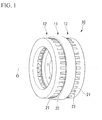
FIG. 1 is a perspective view of an axial gap motor according to an embodiment of the present invention. -
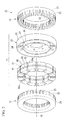
FIG. 2 is an exploded perspective view of a rotor of an axial gap motor according to the present embodiment. -
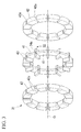
FIG. 3 is an exploded perspective view of a main part of the rotor of the axial gap motor according to the present embodiment. -
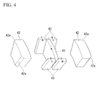
FIG. 4 is an exploded perspective view of the main part of the rotor of the axial gap motor according to the present embodiment. -
FIG. 5 is a side view of main parts of a stator and the rotor of the axial gap motor according to the present embodiment as viewed from an outside to an inside in a radial direction, where reference numeral a1 denotes a magnet flux and reference numeral a2 denotes a short-circuit flux. -
FIG. 6 is a perspective view of the main part of the rotor of the axial gap motor according to the present embodiment. -
FIG. 7 is a perspective view of a main part of a rotor of an axial gap motor according to an example modified from the present embodiment of the present invention. -
FIG. 8 is an exploded perspective view of the main part of the rotor of the axial gap motor according to the modified example. -
FIG. 9 is a side view of main parts of a stator and the rotor of the axial gap motor according to the modified example as viewed from an outside to an inside in a radial direction, where reference numeral a1 denotes a magnet flux and reference numeral a2 denotes a short-circuit flux. -
- 10: AXIAL GAP MOTOR
- 11: ROTOR
- 12: STATOR
- 22: TEETH
- 23: SLOT
- 41: MAIN PERMANENT MAGNET PIECE (MAIN MAGNET)
- 42: MAGNETIC MEMBER
- 42a: CHAMFERED PORTION
- 42b: CURVED SURFACE PORTION
- 43: SUB PERMANENT MAGNET PIECE (SUB PERMANENT MAGNET)
- Hereinafter, an axial gap motor according to an embodiment of the invention will be described with reference to the accompanying drawings.
Theaxial gap motor 10 according to the present embodiment is provided with, as illustrated inFIGS. 1 and2 , arotor 11 having a substantially annular shape to rotate around a rotation axis O of theaxial gap motor 10, and a pair ofstators 12 which are opposed to each other with therotor 11 interposed therebetween from the both sides in rotation axis O direction and each of which has a stator winding (not shown) of a plurality of phases to generate a rotating magnetic field for rotating therotor 11. - The
axial gap motor 10 is mounted in a vehicle such as a hybrid vehicle or an electric vehicle as a driving source, and an output shaft thereof is connected to an input shaft of a transmission (not shown) to transmit the driving force of theaxial gap motor 10 to drive wheels (not shown) of the vehicle through the transmission. - When driving force is transmitted to the
axial gap motor 10 from the drive wheels during a reduction in speed of the vehicle, theaxial gap motor 10 functions as a generator to generate a so-called regenerative braking force and recover kinetic energy of the frame of the vehicle into electrical energy (regenerative energy). In addition, for example, in a hybrid vehicle, if a rotation shaft of theaxial gap motor 10 is connected to a crankshaft of an internal-combustion engine (not shown), even in a case where the output of the internal-combustion engine is transmitted to theaxial gap motor 10, theaxial gap motor 10 functions as a generator to generate energy. - Each
stator 12 includes ayoke portion 21 having a substantially annular plate shape, a plurality ofteeth 22 which are provided on a surface of theyoke portion 21 which is opposed to therotor 11 to protrude toward therotor 11 in parallel with the rotation axis O direction at positions with predetermined intervals along a circumferential direction and extend in a radial direction, and a stator winding (not shown) suitably installed between theteeth 22. - Each
stator 12 is, for example, of a 6N type having 6 main poles (for example, U+, V+, W+, U-, V-, and W-) so that the U+, V+, and W+ poles of the one stator (first stator) 12 are opposed to the U-, V-, and W- poles of the other stator (second stator) 12 in the rotation axis O direction.
For example, with regard to a pair of thestators 12 which are opposed to each other in the rotation axis O direction, the 3teeth 22 of thefirst stator 12 which correspond to the U+, V+, W+ poles and the 3teeth 22 of thesecond stator 12 which correspond to the U-, V-, W- poles are opposed to each other in the rotation axis O direction, and conducting states of theteeth 22 of thefirst stator 12 and theteeth 22 of thesecond stator 12 which are opposed to each other in the rotation axis O direction are set to be inverted at an electric angle. - A circumferential width of each of the
teeth 22 is set to be reduced toward the inside from the outside in the radial direction. An interval in the circumferential direction between theteeth 22 which are adjacent to each other in the circumferential direction, that is, a width of aslot 23 extending in the radial direction between theteeth 22 adjacent in the circumferential direction has a predetermined constant value in the radial direction. - The
rotor 11 includes a plurality of mainmagnet pole portions 31, a plurality ofsub magnet portions 32, and arotor frame 33 made of a nonmagnetic material. The mainmagnet pole portions 31 and thesub magnet portions 32 are alternately arranged in the circumferential direction and are accommodated in therotor frame 33. - The
rotor frame 33 includes an outer-peripheralcylindrical portion 35 and an inner-peripheralcylindrical portion 36 which are connected with a plurality ofradial ribs 34 arranged at predetermined intervals along the circumferential direction, and aconnection portion 37 which has an annular shape protruding inwards from an inner peripheral surface of the inner-peripheralcylindrical portion 36 to be connected to an external drive shaft (for example, an input shaft of a transmission of a vehicle).
In this embodiment, the inner-peripheralcylindrical portion 36 of therotor frame 33 is connected to the external drive shaft, so that a radially inner side of theradial rib 34 serves as a shaft part side, and a radially outer side of theradial rib 34 serves as a rim part side. - A plurality of the main
magnet pole portions 31 accommodated in therotor frame 33 are interposed between the inner-peripheralcylindrical portion 36 and the outer-peripheralcylindrical portion 35 from both sides of the radial direction and are arranged to be adjacent one another in the circumferential direction through theradial ribs 34. - The main
magnet pole portion 31 includes, as illustrated inFIGS. 3 and4 , a mainpermanent magnet piece 41 which has substantially sectorial plate shape and is magnetized in a thickness direction (that is, the rotation axis O direction) and a pair ofmagnetic members 42 between which the mainpermanent magnet piece 41 is interposed from both sides of the thickness direction. The mainmagnet pole portions 31 which are adjacent in the circumferential direction are set so that magnetization directions of their mainpermanent magnet pieces 41 are different. That is, to the mainmagnet pole portion 31 having the mainpermanent magnet piece 41 of which one side in the rotation axis O direction is magnetized with N pole, the mainmagnet pole portion 31 having the mainpermanent magnet piece 41 of which one side in the rotation axis O direction is magnetized with S pole is adjacent. - A plurality of the main
magnet pole portions 31 accommodated in therotor frame 33 are interposed between the inner-peripheralcylindrical portion 36 and the outer-peripheralcylindrical portion 35 from the both sides of the radial direction and are arranged to be adjacent one another in the circumferential direction through theradial ribs 34.
That is, in therotor frame 33, the mainpermanent magnet piece 41 of each mainmagnet pole portion 31 is interposed between the tworadial ribs 34 from the both sides of the circumferential direction. - A pair of the
magnetic members 42 which cover one surface and the other surface in the thickness direction of the mainpermanent magnet pieces 41 have a substantially sectorial cross-sectional shape in the thickness direction which is the same as the cross-sectional shape of the mainpermanent magnet piece 41.
Both end portions of themagnetic member 42 in the circumferential direction are provided withchamfered portions 42a having a chamfered shape. - The
sub magnet portion 32 includes, for example, a pair of subpermanent magnet pieces 43 between which theradial rib 34 is interposed from both sides of the rotation axis O direction in therotor frame 33. A pair of the subpermanent magnet pieces 43 which are opposed to each other in the rotation axis O direction are magnetized, for example, as illustrated inFIG. 4 , in the rotation axis O direction and a direction (substantially the circumferential direction) perpendicular to the radial direction so that their magnetization directions are different. - In the
rotor frame 33, the subpermanent magnet pieces 43 of thesub magnet portions 32 which are adjacent to each other in the circumferential direction have themagnetic member 42 of the mainmagnet pole portion 31 interposed therebetween from the both sides of the circumferential direction.
InFIG. 2 illustrating therotor frame 33 and components other than the rotor frame 33 (that is, the mainmagnet pole portions 31 and the sub magnet portions 32) of therotor 11 separately, and inFIG. 3 illustrating the components of therotor 11 other than the rotor frame 33 (that is, the mainmagnet pole portions 31 and the sub magnet portions 32), aspace portion 34a in which theradial rib 34 of therotor frame 33 is placed is formed between a pair of the subpermanent magnet pieces 43 opposed in the rotation axis O direction and the mainpermanent magnet pieces 41 adjacent in the circumferential direction. - A pair of the sub
permanent magnet pieces 43 opposed to each other in the circumferential direction through themagnetic member 42 have, for example, different magnetization directions as illustrated inFIG. 4 .
With regard to a pair of the subpermanent magnet pieces 43 disposed on the one side in the rotation axis O direction, the same poles as the pole of the one side of the mainpermanent magnet piece 41 magnetized in the rotation axis O direction are opposed to each other, and with regard to a pair of the subpermanent magnet pieces 43 disposed on the other side in the rotation axis O direction, the same poles as the pole of the other side of the mainpermanent magnet piece 41 magnetized in the rotation axis O direction are opposed to each other. - That is, for example, with respect to the main
permanent magnet piece 41 of which the one side has the N pole and the other side has the S pole in the rotation axis O direction, a pair of the subpermanent magnet pieces 43 between which themagnetic member 42 is interposed from the both sides of the circumferential direction on the one side of the rotation axis O direction are disposed so that their N poles are opposed to each other in the circumferential direction, and a pair of the subpermanent magnet pieces 43 between which themagnetic member 42 is interposed from the both sides of the circumferential direction on the other side of the rotation axis O direction are disposed so that their S poles are opposed to each other in the circumferential direction.
Accordingly, due to a flux lens effect caused by a so-called Halbach array of permanent magnets, fluxes of the mainpermanent magnet pieces 41 and the subpermanent magnet pieces 43 are converged together, and effective fluxes interlinked with eachstator 12 relatively increase. - For example, as illustrated in
FIG. 5 , a length LY (>LS) of themagnetic member 42 in the rotation axis O direction is larger than a length LS of the subpermanent magnet piece 43 in the rotation axis O direction. In addition, inFIG. 5 , reference numeral a1 denotes a magnet flux, and reference numeral a2 denotes a short-circuit flux.
With regard to an outer-peripheral circumferential width B and an inner-peripheral circumferential width b of a front end portion of thetooth 22 of thestator 12, and a first interval h between themagnetic members 42 which are adjacent in the circumferential direction (that is, an interval between inner ends p along the circumferential direction of their chamferedportions 42a) and a second interval H (that is, an interval between outer ends q along the circumferential direction of their chamferedportions 42a), the second interval H is equal to or greater than the outer-peripheral circumferential width B, and the first interval h is equal to or greater than the inner-peripheral circumferential width b. - As described above, in the
axial gap motor 10 according to this embodiment, the subpermanent magnet piece 43 magnetized in a direction perpendicular to the magnetization direction of the mainpermanent magnet piece 41 is provided on a circumferential end portion of the mainpermanent magnet piece 41 to exhibit the flux lens effect caused by a so-called Halbach array of the mainpermanent magnet piece 41 and the subpermanent magnet piece 43, so that the fluxes of the mainpermanent magnet piece 41 and the subpermanent magnet piece 43 are converted, thereby increasing the amount of flux interlinked with the stator winding of thestator 12.
In addition, themagnetic member 42 is provided on a surface of the mainpermanent magnet piece 41, so that reluctance torque can be increased. In addition, the degradation in permeance of the mainpermanent magnet piece 41 can be prevented, so that the demagnetization of the mainpermanent magnet piece 41 can be suppressed.
Moreover, the length LY (>LS) of themagnetic member 42 in the rotation axis O direction is larger than the length LS of the subpermanent magnet piece 43 in the rotation axis O direction so as to protrude toward thestator 12 as compared with the subpermanent magnet piece 43. Therefore, the reluctance torque can further be increased, thereby increasing torque that can be output, without increasing the amount of permanent magnets for therotor 11. - In addition, since the circumferential end portion of the
magnetic member 42 has a chamfered shape, a void can be enlarged for the front end portion of thetooth 22 protruding from thestator 12 toward therotor 11, for example, a front end (for example, a front end e shown inFIG. 5 ) which is more likely to have flux leakage due to its surface bend, for example, at substantially right angle or the like, so that the circumferential end portion of themagnetic member 42 can be given a shape which is less likely to cause flux leakage. Accordingly, the generation of a short-circuit loop of magnet flux (especially, a magnet flux of the sub permanent magnet piece 43) between the front end portion of thetooth 22 and the circumferential end portion of themagnetic member 42 is suppressed, thereby preventing the degradation in torque potential. Further, due to the chamferedportion 42a, the generation of torque ripple can be suppressed. - In addition, the second interval H between the
magnetic members 42 is equal to or greater than the outer-peripheral circumferential width B of thetooth 22, and the first interval h between themagnetic members 42 is equal to or greater than the inner-peripheral circumferential width b of thetooth 22, so that the generation of a short-circuit loop of magnet flux (especially, a magnet flux of the sub permanent magnet piece 43) can further be suppressed, thereby preventing the degradation of torque potential. - In addition, in the embodiment described above, for example, as illustrated in
FIG. 6 , the chamferedportion 42a having a chamfered shape with the uniform width W from the outside toward the inside in the radial direction is provided for the circumferential end portions of themagnetic member 42. However, the embodiment is not limited thereto, and for example, as illustrated inFIGS. 7 and8 , a chamfered portion 42c of which a width changes to be reduced toward the inside from the outside in the radial direction may be provided. - In this case, the circumferential width of each of the
teeth 22 provided along the circumferential direction of thestator 12 changes to be reduced from the outside toward the inside in the radial direction. On the contrary, the circumferential width of the subpermanent magnet piece 43 is the uniform from the outside to the inside in the radial direction. The circumferential interval between themagnetic members 42 between which the subpermanent magnet piece 43 is interposed from the both sides of the circumferential direction is uniform from the outside toward the inside in the radial direction. Therefore, the distance between the front end portion of thetooth 22 and the circumferential end portion of themagnetic member 42 changes to be increased from the outside toward the inside in the radial direction. Accordingly, since the chamfered portion 42c of the circumferential end portion of themagnetic member 42 changes to be reduced in size from the outside toward the inside in the radial direction, the distance between the front end portion of thetooth 22 and the chamfered portion 42c of themagnetic member 42 can be made uniform from the outside toward the inside in the radial direction. Therefore, for example, it is possible to prevent the generation of points where flux leakage is likely to occur due to nonuniformity in the distance in the radial direction. - In addition, in the embodiment described above, the circumferential both end portions of the
magnetic member 42 are provided with thechamfered portions 42a and 42c having a chamfered shape. However, the embodiment is not limited thereto, and for example, as illustrated inFIG. 9 , instead of the chamferedportion 42a, the circumferential end portion of themagnetic member 42 may be provided with acurved surface portion 42b having a substantially arc shaped cross-section in the radial direction (inFIG. 9 , reference numeral a1 denotes a flux, and reference numeral a2 denotes a short-circuit flux). In addition, thecurved surface portion 42b may change reduced in size from the outside toward the inside in the radial direction. - While preferred embodiments of the present invention have been described and illustrated above, it should be understood that these are exemplary of the present invention and are not to be considered as limiting. Additions, omissions, substitutions, and other modifications can be made without departing from the spirit or scope of the present invention. Accordingly, the present invention is not to be considered as being limited by the foregoing description, and is only limited by the scope of the appended claims.
- In the axial gap motor according to the invention, the circumferential end portion of the main magnet is provided with the sub permanent magnet magnetized in a direction perpendicular to the magnetization direction of the main magnet, so that due to a flux lens effect caused by a so-called Halbach array of the main magnet and the sub permanent magnet, the fluxes of the main magnet and the sub permanent magnet can be converged. Therefore, the amount of flux interlinked with the stator winding of the stator can be increased.
Claims (5)
- An axial gap motor comprising:a rotor that is rotatable around a rotation axis; anda pair of stators that are opposed to each other with the rotor interposed therebetween from both sides in a rotation axis direction which is parallel with the rotation axis of the rotor,wherein the rotor includes:a plurality of main magnets arranged in a circumferential direction so that a flux direction is parallel with the rotation axis direction;a sub permanent magnet which is disposed in the vicinity of a circumferential end portion of the main magnet and is magnetized in a direction perpendicular to the rotation axis direction and a radial direction; anda magnetic member which is provided on a surface of at least one of the one side and the other side in the rotation axis direction of the main magnet, andwherein a length of the magnetic member in the rotation axis direction is larger than a length of the sub permanent magnet in the rotation axis direction.
- The axial gap motor according to claim 1, wherein a circumferential end portion of the magnetic member is provided with a chamfered portion having a chamfered shape.
- The axial gap motor according to claim 2, wherein the chamfered portion changes to be reduced in size from an outside toward an inside in the radial direction.
- The axial gap motor according to claim 1, wherein a circumferential end portion of the magnetic member is provided with a curved surface portion having a substantially arc shaped cross-section in the radial direction.
- The axial gap motor according to claim 4, wherein the curved surface portion changes to be reduced in size from an outside toward an inside in the radial direction.
Applications Claiming Priority (2)
| Application Number | Priority Date | Filing Date | Title |
|---|---|---|---|
| JP2007223058A JP4961302B2 (en) | 2007-08-29 | 2007-08-29 | Axial gap type motor |
| PCT/JP2008/062383 WO2009028266A1 (en) | 2007-08-29 | 2008-07-09 | Axial gap type motor |
Publications (3)
| Publication Number | Publication Date |
|---|---|
| EP2184838A1 true EP2184838A1 (en) | 2010-05-12 |
| EP2184838A4 EP2184838A4 (en) | 2011-11-16 |
| EP2184838B1 EP2184838B1 (en) | 2012-12-05 |
Family
ID=40386995
Family Applications (1)
| Application Number | Title | Priority Date | Filing Date |
|---|---|---|---|
| EP08777992A Not-in-force EP2184838B1 (en) | 2007-08-29 | 2008-07-09 | Axial gap type motor |
Country Status (5)
| Country | Link |
|---|---|
| US (1) | US8053942B2 (en) |
| EP (1) | EP2184838B1 (en) |
| JP (1) | JP4961302B2 (en) |
| CN (1) | CN101779366B (en) |
| WO (1) | WO2009028266A1 (en) |
Cited By (2)
| Publication number | Priority date | Publication date | Assignee | Title |
|---|---|---|---|---|
| TWI489738B (en) * | 2011-11-30 | 2015-06-21 | Hu Hsien Wen | Axial flux permanent magnet generator |
| EP2582016A3 (en) * | 2011-10-10 | 2016-02-17 | Samsung Electronics Co., Ltd | Motor and rotor of a motor |
Families Citing this family (30)
| Publication number | Priority date | Publication date | Assignee | Title |
|---|---|---|---|---|
| WO2007141948A1 (en) * | 2006-06-06 | 2007-12-13 | Honda Motor Co., Ltd. | Motor and motor control device |
| US20100141075A1 (en) * | 2006-12-06 | 2010-06-10 | Honda Motor Co., Ltd | Axial gap motor |
| JP2008271640A (en) * | 2007-04-17 | 2008-11-06 | Honda Motor Co Ltd | Axial gap type motor |
| JP4707696B2 (en) * | 2007-06-26 | 2011-06-22 | 本田技研工業株式会社 | Axial gap type motor |
| JP4729551B2 (en) | 2007-10-04 | 2011-07-20 | 本田技研工業株式会社 | Axial gap type motor |
| US7977843B2 (en) * | 2007-10-04 | 2011-07-12 | Honda Motor Co., Ltd. | Axial gap type motor |
| TWI405388B (en) * | 2008-03-19 | 2013-08-11 | Hoganas Ab Publ | Permanent magnet machine |
| EP2355313A4 (en) * | 2008-12-03 | 2012-10-03 | Honda Motor Co Ltd | Axial gap motor and method of manufacturing rotor for same |
| JP5046051B2 (en) * | 2009-01-28 | 2012-10-10 | 本田技研工業株式会社 | Axial gap type motor |
| JP5027169B2 (en) * | 2009-01-30 | 2012-09-19 | 本田技研工業株式会社 | Axial gap type motor and rotor manufacturing method thereof |
| JP2010207046A (en) * | 2009-03-06 | 2010-09-16 | Nisca Corp | Generator and power generation system with the same |
| JP2010207052A (en) * | 2009-03-06 | 2010-09-16 | Nisca Corp | Power generator and power generation system with the same |
| CN102487234B (en) * | 2010-12-03 | 2015-01-07 | 台达电子工业股份有限公司 | Rotating electrical machines and their rotors |
| WO2012084905A1 (en) * | 2010-12-22 | 2012-06-28 | Höganäs Ab (Publ) | Stator for a modulated pole machine |
| JP5538447B2 (en) * | 2012-01-19 | 2014-07-02 | 富士重工業株式会社 | Axial gap type power generator |
| KR101967806B1 (en) * | 2012-08-21 | 2019-04-10 | 삼성전자 주식회사 | Rotor and electric motor comprising the same |
| TWI483514B (en) * | 2012-11-09 | 2015-05-01 | Ind Tech Res Inst | Axial-flux halbach rotor |
| US10491087B2 (en) | 2013-10-01 | 2019-11-26 | Whirlpool Corporation | Method of manufacturing a rotor for an electric motor for a washing machine |
| US20150091410A1 (en) * | 2013-10-02 | 2015-04-02 | Regal Beloit Australia Pty Ltd. | Axial flux electrical machines and methods of manufacturing the same. |
| JP5726386B1 (en) * | 2014-03-18 | 2015-05-27 | 三菱電機株式会社 | Permanent magnet motor rotor |
| US10020717B2 (en) | 2014-08-13 | 2018-07-10 | Wisconsin Alumni Research Foundation | Dual stator, flux switching permanent magnet machine |
| US10141822B2 (en) * | 2015-05-04 | 2018-11-27 | Launchpoint Technologies, Inc. | Axial flux brushless permanent magnet electrical machine rotor |
| US9859777B2 (en) * | 2015-05-18 | 2018-01-02 | Wisconsin Alumni Research Foundation | Axial flux switching permanent magnet machine |
| KR101838014B1 (en) * | 2015-12-06 | 2018-04-26 | 한승주 | High Speed Motor |
| US10916984B2 (en) * | 2018-03-27 | 2021-02-09 | Regal Beloit America, Inc. | Axial flux rotor and axial flux electric machine |
| GB201808132D0 (en) * | 2018-05-18 | 2018-07-11 | Electronica Products Ltd | Electrical Machine |
| CN112703661B (en) * | 2018-09-18 | 2025-01-07 | 住友电气工业株式会社 | Rotating electric machines |
| CN113131644A (en) * | 2019-12-31 | 2021-07-16 | 日本电产株式会社 | Rotor core and motor having the same |
| CN112467952B (en) * | 2020-11-19 | 2022-01-25 | 东南大学 | Rotor permanent magnet type double-stator axial magnetic field hybrid permanent magnet flux switching motor |
| CN114301204B (en) * | 2021-12-17 | 2023-04-07 | 石镇德 | Axial flux synchronous reluctance motor |
Family Cites Families (95)
| Publication number | Priority date | Publication date | Assignee | Title |
|---|---|---|---|---|
| US336087A (en) | 1886-02-16 | Armature for dynamo-electric machines | ||
| US2154146A (en) | 1935-09-02 | 1939-04-11 | John Edward Becker | Electric motor, dynamo, and the like |
| US2632861A (en) | 1951-03-16 | 1953-03-24 | Gen Electric | Frame structure for dynamo-electric machines |
| US3108200A (en) | 1960-03-01 | 1963-10-22 | Otis Elevator Co | Dynamo stator assemblies having resiliently mounted field coils |
| US3465188A (en) | 1967-08-11 | 1969-09-02 | Wagner Electric Corp | Laminated motor stator with bonding material,through bolts,and welds |
| CH474890A (en) | 1968-03-07 | 1969-06-30 | Beteiligungs Ag Haustechnik | Electric rotary machine |
| US3762042A (en) * | 1971-06-17 | 1973-10-02 | Tokai Cold Forming Co Ltd | Method of manufacturing a core segment for a disc type induction motor rotor |
| FR2211786B1 (en) | 1972-12-23 | 1978-11-10 | Eda Overseas Ltd | |
| US3956651A (en) | 1974-11-05 | 1976-05-11 | General Electric Company | Wire stator structure |
| US4095150A (en) | 1976-07-12 | 1978-06-13 | Karlheinz Senckel | Two-phase asynchronous motor |
| US4363988A (en) | 1978-06-12 | 1982-12-14 | General Electric Company | Induction disk motor with metal tape components |
| JPS5553161A (en) | 1978-10-13 | 1980-04-18 | Fujitsu Ltd | Magnetic polar construction |
| EP0052179B1 (en) | 1980-07-29 | 1986-03-26 | Card-O-Matic Pty Ltd. | Axial flux electric machine |
| JPS59144352A (en) | 1983-02-01 | 1984-08-18 | Seiko Epson Corp | Multipolar magnetized magnet for rotating electrical machines |
| JPS59230453A (en) | 1983-06-13 | 1984-12-25 | Matsushita Electric Ind Co Ltd | Axial gap type induction motor |
| DE3713610A1 (en) | 1987-04-23 | 1988-11-10 | Heldt & Rossi Servoelektronik | ROTOR FOR ELECTRIC MOTOR |
| JPH0279174A (en) | 1988-09-16 | 1990-03-19 | Nec Corp | Image data moving process controller |
| JPH083188Y2 (en) | 1988-12-02 | 1996-01-29 | 株式会社東芝 | Brushless motor |
| JPH02179246A (en) | 1988-12-28 | 1990-07-12 | Fanuc Ltd | Stator construction of built-in motor |
| US4996457A (en) | 1990-03-28 | 1991-02-26 | The United States Of America As Represented By The United States Department Of Energy | Ultra-high speed permanent magnet axial gap alternator with multiple stators |
| US5245238A (en) | 1991-04-30 | 1993-09-14 | Sundstrand Corporation | Axial gap dual permanent magnet generator |
| US5334899A (en) | 1991-09-30 | 1994-08-02 | Dymytro Skybyk | Polyphase brushless DC and AC synchronous machines |
| US5955809A (en) | 1992-08-17 | 1999-09-21 | Intellectual Property Law Department Sundstrand Corporation | Permanent magnet generator with auxiliary winding |
| US5394321A (en) * | 1992-09-02 | 1995-02-28 | Electric Power Research Institute, Inc. | Quasi square-wave back-EMF permanent magnet AC machines with five or more phases |
| US5387854A (en) | 1992-09-02 | 1995-02-07 | Electric Power Research Institute, Inc. | Method of torque notch minimization for quasi square wave back EMF permanent magnet synchronous machines with voltage source drive |
| JPH06205554A (en) | 1992-11-16 | 1994-07-22 | Yaskawa Electric Corp | Synchronous rotating electric machine rotor |
| US5397953A (en) * | 1993-11-17 | 1995-03-14 | The United States Of America As Represented By The Secretary Of The Navy | Stator for disc type electric motor |
| US5671524A (en) | 1994-09-19 | 1997-09-30 | Electric Power Research Institute, Inc. | Magnetic annealing of amorphous alloy for motor stators |
| JPH08251901A (en) | 1995-03-03 | 1996-09-27 | Canon Inc | Electromagnetic drive |
| IL116631A0 (en) | 1995-03-21 | 1996-03-31 | Kenetech Windpower Inc | Doubly-salient permanent-magnet machine |
| FR2739505B1 (en) | 1995-09-29 | 1997-12-19 | Technicatome | DISCOIDAL ASYNCHRONOUS ELECTRIC MOTOR |
| US5925965A (en) | 1996-09-06 | 1999-07-20 | Emerson Electric Co. | Axial flux reluctance machine with two stators driving a rotor |
| JPH10164799A (en) | 1996-11-26 | 1998-06-19 | Hitachi Ltd | Induction motor |
| JPH10164779A (en) | 1996-11-26 | 1998-06-19 | Fuji Electric Co Ltd | Axial gap synchronous machine |
| US5731649A (en) | 1996-12-27 | 1998-03-24 | Caama+E,Otl N+Ee O; Ramon A. | Electric motor or generator |
| JPH10271784A (en) | 1997-03-21 | 1998-10-09 | Fuji Electric Co Ltd | Axial gap type permanent magnet excitation synchronous machine |
| JP3746372B2 (en) | 1998-04-16 | 2006-02-15 | 株式会社日立製作所 | Permanent magnet type rotating electric machine and electric vehicle using the same |
| US6960860B1 (en) | 1998-06-18 | 2005-11-01 | Metglas, Inc. | Amorphous metal stator for a radial-flux electric motor |
| JP2000197301A (en) | 1998-12-24 | 2000-07-14 | Sony Corp | motor |
| JP4200400B2 (en) | 1999-03-09 | 2008-12-24 | 株式会社安川電機 | Axial gap type micro motor |
| JP3062085U (en) | 1999-03-11 | 1999-09-28 | 王 譽 燕 | Opposite-axis magnetic brushless DC motor |
| JP2001057753A (en) * | 1999-08-12 | 2001-02-27 | Mitsubishi Heavy Ind Ltd | Axial gap motor |
| JP2001136721A (en) | 1999-08-26 | 2001-05-18 | Toyota Motor Corp | Axial gap type permanent magnet synchronous machine |
| US6373162B1 (en) | 1999-11-11 | 2002-04-16 | Ford Global Technologies, Inc. | Permanent magnet electric machine with flux control |
| JP2001251817A (en) | 2000-03-07 | 2001-09-14 | Moric Co Ltd | Assembly device for permanent magnet field motor |
| JP3661582B2 (en) | 2000-09-28 | 2005-06-15 | 日産自動車株式会社 | Rotor for magnet motor |
| ATE311030T1 (en) | 2002-03-22 | 2005-12-15 | Ebm Papst St Georgen Gmbh & Co | INNER ROTOR MOTOR |
| US7230359B2 (en) | 2002-03-22 | 2007-06-12 | Ebm-Papst St. Georgen Gmbh & Co. Kg | Electric motor with poles shaped to minimize cogging torque |
| JP4003058B2 (en) | 2002-07-17 | 2007-11-07 | 株式会社富士通ゼネラル | Induction motor |
| US7144468B2 (en) | 2002-09-05 | 2006-12-05 | Metglas, Inc. | Method of constructing a unitary amorphous metal component for an electric machine |
| US6995494B2 (en) | 2002-10-14 | 2006-02-07 | Deere & Company | Axial gap brushless DC motor |
| US7230361B2 (en) | 2003-01-31 | 2007-06-12 | Light Engineering, Inc. | Efficient high-speed electric device using low-loss materials |
| DE10326167B4 (en) | 2003-06-10 | 2008-10-02 | Siemens Ag | Permanent magnet synchronous motor |
| JP2005094955A (en) | 2003-09-18 | 2005-04-07 | Toyota Central Res & Dev Lab Inc | Axial permanent magnet motor |
| DE202004016534U1 (en) | 2003-11-05 | 2005-01-05 | Ebm-Papst St. Georgen Gmbh & Co. Kg | electric motor |
| JP4193685B2 (en) | 2003-12-15 | 2008-12-10 | 日産自動車株式会社 | Axial gap motor structure |
| US7187098B2 (en) | 2004-03-03 | 2007-03-06 | Kabushikikaisha Equos Research | Axial gap rotating electrical machine |
| JP4529500B2 (en) | 2004-03-18 | 2010-08-25 | 株式会社エクォス・リサーチ | Axial gap rotating electric machine |
| JP2005318782A (en) | 2004-03-31 | 2005-11-10 | Nissan Motor Co Ltd | Axial gap motor cooling structure |
| JP2005304245A (en) * | 2004-04-15 | 2005-10-27 | Nissan Motor Co Ltd | Axial gap type rotating electrical machine |
| JP4432616B2 (en) * | 2004-05-26 | 2010-03-17 | 日産自動車株式会社 | Axial gap type rotating electrical machine |
| JP4608967B2 (en) | 2004-06-29 | 2011-01-12 | 日産自動車株式会社 | Rotor structure and rotor manufacturing method for disk-type rotating electrical machine |
| JP2006025482A (en) * | 2004-07-06 | 2006-01-26 | Nissan Motor Co Ltd | Rotor structure and rotor manufacturing method for disk-type rotating electrical machine |
| JP2006050745A (en) * | 2004-08-03 | 2006-02-16 | Nissan Motor Co Ltd | Axial gap rotating electric machine |
| JP2006166635A (en) | 2004-12-08 | 2006-06-22 | Nissan Motor Co Ltd | Rotating electric machine |
| KR100904353B1 (en) | 2005-01-19 | 2009-06-23 | 다이킨 고교 가부시키가이샤 | Rotor, axial gap type motor, motor driving method, and compressor |
| JP2006222131A (en) * | 2005-02-08 | 2006-08-24 | Neomax Co Ltd | Permanent magnet body |
| DE602005018605D1 (en) | 2005-04-22 | 2010-02-11 | Infranor Holding S A | System for attaching permanent magnets |
| JP2006353078A (en) * | 2005-05-17 | 2006-12-28 | Nissan Motor Co Ltd | Axial gap type rotating electrical machine |
| JP2006345627A (en) | 2005-06-08 | 2006-12-21 | Nissan Motor Co Ltd | Rotor structure of rotating electrical machine |
| JP4692090B2 (en) * | 2005-06-16 | 2011-06-01 | 株式会社富士通ゼネラル | Axial air gap type electric motor |
| JP4904736B2 (en) | 2005-07-21 | 2012-03-28 | 日産自動車株式会社 | Rotating electric machine stator |
| JP2007037210A (en) | 2005-07-22 | 2007-02-08 | Nissan Motor Co Ltd | Rotating electrical machine rotor |
| JP2007053844A (en) * | 2005-08-17 | 2007-03-01 | Asmo Co Ltd | Fan motor |
| JP2007089270A (en) | 2005-09-20 | 2007-04-05 | Toyota Central Res & Dev Lab Inc | Axial type motor and its rotor |
| JP2007104819A (en) * | 2005-10-05 | 2007-04-19 | Nissan Motor Co Ltd | Rotating electric machine |
| JP2007151321A (en) | 2005-11-29 | 2007-06-14 | Nissan Motor Co Ltd | Rotating electrical machine rotor |
| JP5108236B2 (en) | 2006-02-08 | 2012-12-26 | 本田技研工業株式会社 | Rotor for motor |
| JP4955282B2 (en) | 2006-02-21 | 2012-06-20 | 武内プレス工業株式会社 | Manufacturing method of closed membrane tube container |
| WO2007141948A1 (en) | 2006-06-06 | 2007-12-13 | Honda Motor Co., Ltd. | Motor and motor control device |
| JP4169055B2 (en) | 2006-07-14 | 2008-10-22 | ダイキン工業株式会社 | Rotating electric machine |
| JP5176298B2 (en) | 2006-08-11 | 2013-04-03 | 日産自動車株式会社 | Variable air gap type rotating electrical machine |
| JP2008104278A (en) | 2006-10-18 | 2008-05-01 | Honda Motor Co Ltd | motor |
| US7737594B2 (en) | 2006-12-01 | 2010-06-15 | Honda Motor Co., Ltd. | Axial gap type motor |
| JP4906606B2 (en) | 2006-12-06 | 2012-03-28 | 本田技研工業株式会社 | Axial gap type motor |
| US20100141075A1 (en) | 2006-12-06 | 2010-06-10 | Honda Motor Co., Ltd | Axial gap motor |
| JP4394115B2 (en) | 2006-12-26 | 2010-01-06 | 本田技研工業株式会社 | Axial gap type motor |
| JP2008271640A (en) | 2007-04-17 | 2008-11-06 | Honda Motor Co Ltd | Axial gap type motor |
| JP4707696B2 (en) | 2007-06-26 | 2011-06-22 | 本田技研工業株式会社 | Axial gap type motor |
| US7977843B2 (en) | 2007-10-04 | 2011-07-12 | Honda Motor Co., Ltd. | Axial gap type motor |
| JP4729551B2 (en) | 2007-10-04 | 2011-07-20 | 本田技研工業株式会社 | Axial gap type motor |
| US7906883B2 (en) | 2008-06-02 | 2011-03-15 | Honda Motor Co., Ltd. | Axial gap motor |
| US20090295102A1 (en) * | 2008-06-02 | 2009-12-03 | Mckenzie Daniel A | Formed in place over-mold seal |
| US8049389B2 (en) | 2008-06-02 | 2011-11-01 | Honda Motor Co., Ltd. | Axial gap motor |
| JP4678549B2 (en) | 2008-10-09 | 2011-04-27 | 本田技研工業株式会社 | Axial gap type motor |
-
2007
- 2007-08-29 JP JP2007223058A patent/JP4961302B2/en not_active Expired - Fee Related
-
2008
- 2008-07-09 EP EP08777992A patent/EP2184838B1/en not_active Not-in-force
- 2008-07-09 CN CN2008801026726A patent/CN101779366B/en not_active Expired - Fee Related
- 2008-07-09 WO PCT/JP2008/062383 patent/WO2009028266A1/en not_active Ceased
- 2008-07-09 US US12/670,601 patent/US8053942B2/en not_active Expired - Fee Related
Cited By (3)
| Publication number | Priority date | Publication date | Assignee | Title |
|---|---|---|---|---|
| EP2582016A3 (en) * | 2011-10-10 | 2016-02-17 | Samsung Electronics Co., Ltd | Motor and rotor of a motor |
| US9608484B2 (en) | 2011-10-10 | 2017-03-28 | Samsung Electronics Co., Ltd. | Motor and rotor of a motor having a plurality of magnet groups |
| TWI489738B (en) * | 2011-11-30 | 2015-06-21 | Hu Hsien Wen | Axial flux permanent magnet generator |
Also Published As
| Publication number | Publication date |
|---|---|
| CN101779366A (en) | 2010-07-14 |
| CN101779366B (en) | 2012-03-21 |
| US20100231079A1 (en) | 2010-09-16 |
| JP4961302B2 (en) | 2012-06-27 |
| EP2184838B1 (en) | 2012-12-05 |
| JP2009060678A (en) | 2009-03-19 |
| WO2009028266A1 (en) | 2009-03-05 |
| EP2184838A4 (en) | 2011-11-16 |
| US8053942B2 (en) | 2011-11-08 |
Similar Documents
| Publication | Publication Date | Title |
|---|---|---|
| US8053942B2 (en) | Axial gap motor | |
| US8035266B2 (en) | Axial gap motor | |
| US7737594B2 (en) | Axial gap type motor | |
| US7977843B2 (en) | Axial gap type motor | |
| EP2200154B1 (en) | Axial gap motor | |
| US7906883B2 (en) | Axial gap motor | |
| US7598645B2 (en) | Stress distributing permanent magnet rotor geometry for electric machines | |
| EP1940013B1 (en) | Axial gap motor | |
| US6815858B2 (en) | Permanent magnet rotating electric machine | |
| US8304949B2 (en) | Axial gap motor | |
| US7595575B2 (en) | Motor/generator to reduce cogging torque | |
| CN106357024B (en) | Rotor and motor | |
| US20050179336A1 (en) | Axial gap electric rotary machine | |
| US20140333168A1 (en) | Rotor for a rotary electric machine and rotary electric machine comprising such a rotor | |
| CN103141009B (en) | Synchronous rotating machine with double field rotor | |
| JP4605480B2 (en) | Axial gap type motor | |
| EP4195458B1 (en) | Rotor, electric motor, powertrain and vehicle | |
| JP2016521113A (en) | Rotating electric machine rotor and rotating electric machine equipped with the same | |
| JP2010200480A (en) | Embedded magnetic motor | |
| JP5805046B2 (en) | Vehicle motor and vehicle generator | |
| JP2006304546A (en) | Permanent magnet type reluctance type rotating electrical machine | |
| JP4960749B2 (en) | Axial gap type motor | |
| US20240235360A1 (en) | Magnetic geared rotating machine, power generation system, and drive system | |
| JP2019213417A (en) | Brushless motor | |
| JP4808529B2 (en) | Electric motor |
Legal Events
| Date | Code | Title | Description |
|---|---|---|---|
| PUAI | Public reference made under article 153(3) epc to a published international application that has entered the european phase |
Free format text: ORIGINAL CODE: 0009012 |
|
| 17P | Request for examination filed |
Effective date: 20100125 |
|
| AK | Designated contracting states |
Kind code of ref document: A1 Designated state(s): AT BE BG CH CY CZ DE DK EE ES FI FR GB GR HR HU IE IS IT LI LT LU LV MC MT NL NO PL PT RO SE SI SK TR |
|
| AX | Request for extension of the european patent |
Extension state: AL BA MK RS |
|
| DAX | Request for extension of the european patent (deleted) | ||
| A4 | Supplementary search report drawn up and despatched |
Effective date: 20111017 |
|
| RIC1 | Information provided on ipc code assigned before grant |
Ipc: H02K 21/24 20060101ALI20111011BHEP Ipc: H02K 16/04 20060101AFI20111011BHEP Ipc: H02K 1/27 20060101ALI20111011BHEP |
|
| 17Q | First examination report despatched |
Effective date: 20111124 |
|
| GRAP | Despatch of communication of intention to grant a patent |
Free format text: ORIGINAL CODE: EPIDOSNIGR1 |
|
| GRAS | Grant fee paid |
Free format text: ORIGINAL CODE: EPIDOSNIGR3 |
|
| GRAA | (expected) grant |
Free format text: ORIGINAL CODE: 0009210 |
|
| AK | Designated contracting states |
Kind code of ref document: B1 Designated state(s): AT BE BG CH CY CZ DE DK EE ES FI FR GB GR HR HU IE IS IT LI LT LU LV MC MT NL NO PL PT RO SE SI SK TR |
|
| REG | Reference to a national code |
Ref country code: GB Ref legal event code: FG4D |
|
| REG | Reference to a national code |
Ref country code: CH Ref legal event code: EP |
|
| REG | Reference to a national code |
Ref country code: AT Ref legal event code: REF Ref document number: 587732 Country of ref document: AT Kind code of ref document: T Effective date: 20121215 |
|
| REG | Reference to a national code |
Ref country code: IE Ref legal event code: FG4D |
|
| REG | Reference to a national code |
Ref country code: DE Ref legal event code: R096 Ref document number: 602008020637 Country of ref document: DE Effective date: 20130131 |
|
| REG | Reference to a national code |
Ref country code: AT Ref legal event code: MK05 Ref document number: 587732 Country of ref document: AT Kind code of ref document: T Effective date: 20121205 |
|
| PG25 | Lapsed in a contracting state [announced via postgrant information from national office to epo] |
Ref country code: NO Free format text: LAPSE BECAUSE OF FAILURE TO SUBMIT A TRANSLATION OF THE DESCRIPTION OR TO PAY THE FEE WITHIN THE PRESCRIBED TIME-LIMIT Effective date: 20130305 Ref country code: SE Free format text: LAPSE BECAUSE OF FAILURE TO SUBMIT A TRANSLATION OF THE DESCRIPTION OR TO PAY THE FEE WITHIN THE PRESCRIBED TIME-LIMIT Effective date: 20121205 Ref country code: FI Free format text: LAPSE BECAUSE OF FAILURE TO SUBMIT A TRANSLATION OF THE DESCRIPTION OR TO PAY THE FEE WITHIN THE PRESCRIBED TIME-LIMIT Effective date: 20121205 Ref country code: LT Free format text: LAPSE BECAUSE OF FAILURE TO SUBMIT A TRANSLATION OF THE DESCRIPTION OR TO PAY THE FEE WITHIN THE PRESCRIBED TIME-LIMIT Effective date: 20121205 Ref country code: HR Free format text: LAPSE BECAUSE OF FAILURE TO SUBMIT A TRANSLATION OF THE DESCRIPTION OR TO PAY THE FEE WITHIN THE PRESCRIBED TIME-LIMIT Effective date: 20121205 Ref country code: ES Free format text: LAPSE BECAUSE OF FAILURE TO SUBMIT A TRANSLATION OF THE DESCRIPTION OR TO PAY THE FEE WITHIN THE PRESCRIBED TIME-LIMIT Effective date: 20130316 |
|
| REG | Reference to a national code |
Ref country code: NL Ref legal event code: VDEP Effective date: 20121205 |
|
| REG | Reference to a national code |
Ref country code: LT Ref legal event code: MG4D |
|
| PG25 | Lapsed in a contracting state [announced via postgrant information from national office to epo] |
Ref country code: LV Free format text: LAPSE BECAUSE OF FAILURE TO SUBMIT A TRANSLATION OF THE DESCRIPTION OR TO PAY THE FEE WITHIN THE PRESCRIBED TIME-LIMIT Effective date: 20121205 Ref country code: PL Free format text: LAPSE BECAUSE OF FAILURE TO SUBMIT A TRANSLATION OF THE DESCRIPTION OR TO PAY THE FEE WITHIN THE PRESCRIBED TIME-LIMIT Effective date: 20121205 Ref country code: SI Free format text: LAPSE BECAUSE OF FAILURE TO SUBMIT A TRANSLATION OF THE DESCRIPTION OR TO PAY THE FEE WITHIN THE PRESCRIBED TIME-LIMIT Effective date: 20121205 Ref country code: GR Free format text: LAPSE BECAUSE OF FAILURE TO SUBMIT A TRANSLATION OF THE DESCRIPTION OR TO PAY THE FEE WITHIN THE PRESCRIBED TIME-LIMIT Effective date: 20130306 |
|
| PG25 | Lapsed in a contracting state [announced via postgrant information from national office to epo] |
Ref country code: AT Free format text: LAPSE BECAUSE OF FAILURE TO SUBMIT A TRANSLATION OF THE DESCRIPTION OR TO PAY THE FEE WITHIN THE PRESCRIBED TIME-LIMIT Effective date: 20121205 |
|
| PG25 | Lapsed in a contracting state [announced via postgrant information from national office to epo] |
Ref country code: SK Free format text: LAPSE BECAUSE OF FAILURE TO SUBMIT A TRANSLATION OF THE DESCRIPTION OR TO PAY THE FEE WITHIN THE PRESCRIBED TIME-LIMIT Effective date: 20121205 Ref country code: IS Free format text: LAPSE BECAUSE OF FAILURE TO SUBMIT A TRANSLATION OF THE DESCRIPTION OR TO PAY THE FEE WITHIN THE PRESCRIBED TIME-LIMIT Effective date: 20130405 Ref country code: BG Free format text: LAPSE BECAUSE OF FAILURE TO SUBMIT A TRANSLATION OF THE DESCRIPTION OR TO PAY THE FEE WITHIN THE PRESCRIBED TIME-LIMIT Effective date: 20130305 Ref country code: CZ Free format text: LAPSE BECAUSE OF FAILURE TO SUBMIT A TRANSLATION OF THE DESCRIPTION OR TO PAY THE FEE WITHIN THE PRESCRIBED TIME-LIMIT Effective date: 20121205 Ref country code: BE Free format text: LAPSE BECAUSE OF FAILURE TO SUBMIT A TRANSLATION OF THE DESCRIPTION OR TO PAY THE FEE WITHIN THE PRESCRIBED TIME-LIMIT Effective date: 20121205 Ref country code: EE Free format text: LAPSE BECAUSE OF FAILURE TO SUBMIT A TRANSLATION OF THE DESCRIPTION OR TO PAY THE FEE WITHIN THE PRESCRIBED TIME-LIMIT Effective date: 20121205 |
|
| PG25 | Lapsed in a contracting state [announced via postgrant information from national office to epo] |
Ref country code: PT Free format text: LAPSE BECAUSE OF FAILURE TO SUBMIT A TRANSLATION OF THE DESCRIPTION OR TO PAY THE FEE WITHIN THE PRESCRIBED TIME-LIMIT Effective date: 20130405 Ref country code: NL Free format text: LAPSE BECAUSE OF FAILURE TO SUBMIT A TRANSLATION OF THE DESCRIPTION OR TO PAY THE FEE WITHIN THE PRESCRIBED TIME-LIMIT Effective date: 20121205 Ref country code: RO Free format text: LAPSE BECAUSE OF FAILURE TO SUBMIT A TRANSLATION OF THE DESCRIPTION OR TO PAY THE FEE WITHIN THE PRESCRIBED TIME-LIMIT Effective date: 20121205 |
|
| PLBE | No opposition filed within time limit |
Free format text: ORIGINAL CODE: 0009261 |
|
| STAA | Information on the status of an ep patent application or granted ep patent |
Free format text: STATUS: NO OPPOSITION FILED WITHIN TIME LIMIT |
|
| PG25 | Lapsed in a contracting state [announced via postgrant information from national office to epo] |
Ref country code: DK Free format text: LAPSE BECAUSE OF FAILURE TO SUBMIT A TRANSLATION OF THE DESCRIPTION OR TO PAY THE FEE WITHIN THE PRESCRIBED TIME-LIMIT Effective date: 20121205 |
|
| 26N | No opposition filed |
Effective date: 20130906 |
|
| PG25 | Lapsed in a contracting state [announced via postgrant information from national office to epo] |
Ref country code: CY Free format text: LAPSE BECAUSE OF FAILURE TO SUBMIT A TRANSLATION OF THE DESCRIPTION OR TO PAY THE FEE WITHIN THE PRESCRIBED TIME-LIMIT Effective date: 20121205 |
|
| PG25 | Lapsed in a contracting state [announced via postgrant information from national office to epo] |
Ref country code: IT Free format text: LAPSE BECAUSE OF FAILURE TO SUBMIT A TRANSLATION OF THE DESCRIPTION OR TO PAY THE FEE WITHIN THE PRESCRIBED TIME-LIMIT Effective date: 20121205 |
|
| REG | Reference to a national code |
Ref country code: DE Ref legal event code: R097 Ref document number: 602008020637 Country of ref document: DE Effective date: 20130906 |
|
| PG25 | Lapsed in a contracting state [announced via postgrant information from national office to epo] |
Ref country code: MC Free format text: LAPSE BECAUSE OF FAILURE TO SUBMIT A TRANSLATION OF THE DESCRIPTION OR TO PAY THE FEE WITHIN THE PRESCRIBED TIME-LIMIT Effective date: 20121205 |
|
| REG | Reference to a national code |
Ref country code: CH Ref legal event code: PL |
|
| GBPC | Gb: european patent ceased through non-payment of renewal fee |
Effective date: 20130709 |
|
| REG | Reference to a national code |
Ref country code: IE Ref legal event code: MM4A |
|
| REG | Reference to a national code |
Ref country code: DE Ref legal event code: R119 Ref document number: 602008020637 Country of ref document: DE Effective date: 20140201 |
|
| REG | Reference to a national code |
Ref country code: FR Ref legal event code: ST Effective date: 20140331 |
|
| PG25 | Lapsed in a contracting state [announced via postgrant information from national office to epo] |
Ref country code: DE Free format text: LAPSE BECAUSE OF NON-PAYMENT OF DUE FEES Effective date: 20140201 Ref country code: GB Free format text: LAPSE BECAUSE OF NON-PAYMENT OF DUE FEES Effective date: 20130709 Ref country code: LI Free format text: LAPSE BECAUSE OF NON-PAYMENT OF DUE FEES Effective date: 20130731 Ref country code: CH Free format text: LAPSE BECAUSE OF NON-PAYMENT OF DUE FEES Effective date: 20130731 |
|
| PG25 | Lapsed in a contracting state [announced via postgrant information from national office to epo] |
Ref country code: FR Free format text: LAPSE BECAUSE OF NON-PAYMENT OF DUE FEES Effective date: 20130731 |
|
| PG25 | Lapsed in a contracting state [announced via postgrant information from national office to epo] |
Ref country code: IE Free format text: LAPSE BECAUSE OF NON-PAYMENT OF DUE FEES Effective date: 20130709 |
|
| PG25 | Lapsed in a contracting state [announced via postgrant information from national office to epo] |
Ref country code: MT Free format text: LAPSE BECAUSE OF FAILURE TO SUBMIT A TRANSLATION OF THE DESCRIPTION OR TO PAY THE FEE WITHIN THE PRESCRIBED TIME-LIMIT Effective date: 20121205 Ref country code: TR Free format text: LAPSE BECAUSE OF FAILURE TO SUBMIT A TRANSLATION OF THE DESCRIPTION OR TO PAY THE FEE WITHIN THE PRESCRIBED TIME-LIMIT Effective date: 20121205 |
|
| PG25 | Lapsed in a contracting state [announced via postgrant information from national office to epo] |
Ref country code: LU Free format text: LAPSE BECAUSE OF NON-PAYMENT OF DUE FEES Effective date: 20130709 Ref country code: HU Free format text: LAPSE BECAUSE OF FAILURE TO SUBMIT A TRANSLATION OF THE DESCRIPTION OR TO PAY THE FEE WITHIN THE PRESCRIBED TIME-LIMIT; INVALID AB INITIO Effective date: 20080709 |