EP2184430A1 - Vorrichtung zum senkrechten Antrieb von Möbelteilflügeln - Google Patents
Vorrichtung zum senkrechten Antrieb von Möbelteilflügeln Download PDFInfo
- Publication number
- EP2184430A1 EP2184430A1 EP09174083A EP09174083A EP2184430A1 EP 2184430 A1 EP2184430 A1 EP 2184430A1 EP 09174083 A EP09174083 A EP 09174083A EP 09174083 A EP09174083 A EP 09174083A EP 2184430 A1 EP2184430 A1 EP 2184430A1
- Authority
- EP
- European Patent Office
- Prior art keywords
- furniture piece
- cable
- wheel bearing
- bearing plate
- wing
- Prior art date
- Legal status (The legal status is an assumption and is not a legal conclusion. Google has not performed a legal analysis and makes no representation as to the accuracy of the status listed.)
- Withdrawn
Links
- 230000005540 biological transmission Effects 0.000 claims description 10
- 238000004873 anchoring Methods 0.000 claims description 2
- 238000005452 bending Methods 0.000 claims description 2
- 238000010276 construction Methods 0.000 description 1
- 230000007246 mechanism Effects 0.000 description 1
Images

Classifications
-
- E—FIXED CONSTRUCTIONS
- E05—LOCKS; KEYS; WINDOW OR DOOR FITTINGS; SAFES
- E05D—HINGES OR SUSPENSION DEVICES FOR DOORS, WINDOWS OR WINGS
- E05D13/00—Accessories for sliding or lifting wings, e.g. pulleys, safety catches
- E05D13/10—Counterbalance devices
- E05D13/12—Counterbalance devices with springs
- E05D13/123—Counterbalance devices with springs with compression springs
-
- E—FIXED CONSTRUCTIONS
- E05—LOCKS; KEYS; WINDOW OR DOOR FITTINGS; SAFES
- E05D—HINGES OR SUSPENSION DEVICES FOR DOORS, WINDOWS OR WINGS
- E05D13/00—Accessories for sliding or lifting wings, e.g. pulleys, safety catches
- E05D13/10—Counterbalance devices
- E05D13/12—Counterbalance devices with springs
-
- E—FIXED CONSTRUCTIONS
- E05—LOCKS; KEYS; WINDOW OR DOOR FITTINGS; SAFES
- E05Y—INDEXING SCHEME ASSOCIATED WITH SUBCLASSES E05D AND E05F, RELATING TO CONSTRUCTION ELEMENTS, ELECTRIC CONTROL, POWER SUPPLY, POWER SIGNAL OR TRANSMISSION, USER INTERFACES, MOUNTING OR COUPLING, DETAILS, ACCESSORIES, AUXILIARY OPERATIONS NOT OTHERWISE PROVIDED FOR, APPLICATION THEREOF
- E05Y2201/00—Constructional elements; Accessories therefor
- E05Y2201/40—Motors; Magnets; Springs; Weights; Accessories therefor
- E05Y2201/47—Springs
- E05Y2201/478—Gas springs
-
- E—FIXED CONSTRUCTIONS
- E05—LOCKS; KEYS; WINDOW OR DOOR FITTINGS; SAFES
- E05Y—INDEXING SCHEME ASSOCIATED WITH SUBCLASSES E05D AND E05F, RELATING TO CONSTRUCTION ELEMENTS, ELECTRIC CONTROL, POWER SUPPLY, POWER SIGNAL OR TRANSMISSION, USER INTERFACES, MOUNTING OR COUPLING, DETAILS, ACCESSORIES, AUXILIARY OPERATIONS NOT OTHERWISE PROVIDED FOR, APPLICATION THEREOF
- E05Y2201/00—Constructional elements; Accessories therefor
- E05Y2201/60—Suspension or transmission members; Accessories therefor
- E05Y2201/622—Suspension or transmission members elements
- E05Y2201/644—Flexible elongated pulling elements
- E05Y2201/654—Cables
-
- E—FIXED CONSTRUCTIONS
- E05—LOCKS; KEYS; WINDOW OR DOOR FITTINGS; SAFES
- E05Y—INDEXING SCHEME ASSOCIATED WITH SUBCLASSES E05D AND E05F, RELATING TO CONSTRUCTION ELEMENTS, ELECTRIC CONTROL, POWER SUPPLY, POWER SIGNAL OR TRANSMISSION, USER INTERFACES, MOUNTING OR COUPLING, DETAILS, ACCESSORIES, AUXILIARY OPERATIONS NOT OTHERWISE PROVIDED FOR, APPLICATION THEREOF
- E05Y2201/00—Constructional elements; Accessories therefor
- E05Y2201/60—Suspension or transmission members; Accessories therefor
- E05Y2201/622—Suspension or transmission members elements
- E05Y2201/658—Members cooperating with flexible elongated pulling elements
- E05Y2201/668—Pulleys; Wheels
- E05Y2201/67—Pulleys; Wheels in tackles
-
- E—FIXED CONSTRUCTIONS
- E05—LOCKS; KEYS; WINDOW OR DOOR FITTINGS; SAFES
- E05Y—INDEXING SCHEME ASSOCIATED WITH SUBCLASSES E05D AND E05F, RELATING TO CONSTRUCTION ELEMENTS, ELECTRIC CONTROL, POWER SUPPLY, POWER SIGNAL OR TRANSMISSION, USER INTERFACES, MOUNTING OR COUPLING, DETAILS, ACCESSORIES, AUXILIARY OPERATIONS NOT OTHERWISE PROVIDED FOR, APPLICATION THEREOF
- E05Y2900/00—Application of doors, windows, wings or fittings thereof
- E05Y2900/20—Application of doors, windows, wings or fittings thereof for furniture, e.g. cabinets
Definitions
- the present invention relates to a driving device for vertically driving furniture piece wings.
- the device according to the invention in particular, has been designed for application to an inner portion of a furniture piece for allowing the furniture piece wings to be vertically slidably driven in a balanced manner.
- vertically slidably wings are conventionally used in making furniture pieces such as lockers, cabinets and the like.
- the above vertically slidable wings require mechanical driving mechanisms, to allow the wings to be properly operated for a long time.
- the aim of the present invention is to provide such a driving device for vertically slidably driving furniture piece wings which can be applied to an inner part of a furniture piece and which, moreover is adapted to allow the furniture piece wings to be easily slidably driven in a balanced manner.
- a main object of the invention is to provide such a wing driving device which is very advantageous from an ergonomic standpoint.
- Yet another object of the present invention is to provide a strong and reliable wing driving device which is so designed as to exploit in an optimum manner the furniture piece available inner space.
- Yet another object of the present invention is to provide such a furniture piece wing driving device which is very reliable and safe in operation.
- a device for vertically driving furniture piece wings characterized in that said device comprises a multiple hoist structure associated with a body of a furniture piece including at least a vertically movable wing, said structure comprising a gas spring associated, at a top portion thereof, with a fixed wheel bearing plate, integral with a holding body and, at a bottom portion thereof, with a movable wheel bearing plate for entraining a driving cable thereon, said driving cable having an end portion integral with said wing and another portion thereof integral with the fixed wheel bearing plate, said fixed and movable wheel bearing plates having each at least two coaxial pulleys for entraining said cable thereon.
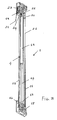
- the furniture piece wing driving device has been generally indicated by the reference number 1 and is applied at the side walls of furniture pieces designed for including at least a vertically slidable wing 3 therein.
- the device according to the present invention which essentially constitutes a hoist structure adapted to balance the weight of the wing 3, comprises a transmission assembly 11, which, at a bottom portion thereof, is associated with the wing 3, and a gas spring 4 having its end portions respectively coupled to a movable wheel bearing plate 16 and a fixed wheel bearing plate 20.
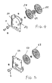
- Said spring gas spring 4 comprises a pneumatic piston 15 having a piston rod 14 to the bottom free end portion thereof 13 said movable wheel bearing plate 16 is coupled.
- Said movable wheel bearing plate 16 comprises a plate-like element supporting two bottom coaxial pulleys 17 and 18 for entraining a driving cable 21 thereon.
- Said bottom coaxial pulleys 17 and 18 are supported, as shown, by a shared pin 6 integral or rigid with said plate 16.
- said piston 15 is operatively coupled to the fixed wheel bearing plate 20 which supports two top coaxial pulleys 22 and 23 and a sheave 19 for entraining said operating cable 21 thereon.
- Said top coaxial pulleys 22 and 23 are supported by a single shared pin 7, integral with said fixed wheel bearing plate 20.
- Said fixed wheel bearing plate 20 comprises moreover an anchoring detent element 24 for a fixed end portion of said driving cable 21.
- the other end portion of the cable 21 is applied to an element affixed to the wing 3, preferably to the transmission assembly 11 integral with said wing 3.
- the arrangement of the transmission pulleys of the above disclosed hoist structure of the inventive device 1 is such that the lengths or portions of the cable 21 between a pulley and a following pulley are substantially parallel to the movement of the wing, and, accordingly, being substantially vertical, without inclinations, thereby limiting a far as possible operating forces in a direction perpendicular to the wing movement.
- An important advantage of the hoist structure according to the present invention is constituted by the coaxial arrangement of the transmission pulleys and by the fact that said transmission pulleys have a comparatively large diameter so designed as to assure a bending radius of the cable 21 so large as to greatly reduce any torsional efforts or strain on said cable thereby providing a satisfactory sliding movement thereof.
- the driving device has a smoother movement and the components thereof are subjected to a minimum wear.
- the sliding movement can be applied to an inner surface of a furniture piece wall, or it can be left exposed to the view on the front of the furniture piece wall or can also be used as a replacement therefor,
- the invention provides a furniture piece driving device which has a very strong and simple construction, allowing to provide a reliable operation in the time.
- the used materials, as well as the contingent size and shapes can be any, depending on requirements.
Landscapes
- Engineering & Computer Science (AREA)
- Mechanical Engineering (AREA)
- Vending Machines For Individual Products (AREA)
- Transmission Devices (AREA)
Applications Claiming Priority (1)
| Application Number | Priority Date | Filing Date | Title |
|---|---|---|---|
| IT002001A ITMI20082001A1 (it) | 2008-11-11 | 2008-11-11 | Dispositivo per la movimentazione verticale di ante per mobili. |
Publications (1)
| Publication Number | Publication Date |
|---|---|
| EP2184430A1 true EP2184430A1 (de) | 2010-05-12 |
Family
ID=41165622
Family Applications (1)
| Application Number | Title | Priority Date | Filing Date |
|---|---|---|---|
| EP09174083A Withdrawn EP2184430A1 (de) | 2008-11-11 | 2009-10-26 | Vorrichtung zum senkrechten Antrieb von Möbelteilflügeln |
Country Status (2)
| Country | Link |
|---|---|
| EP (1) | EP2184430A1 (de) |
| IT (1) | ITMI20082001A1 (de) |
Cited By (2)
| Publication number | Priority date | Publication date | Assignee | Title |
|---|---|---|---|---|
| WO2015128525A1 (es) * | 2014-02-25 | 2015-09-03 | Arcoiza Lopez Roberto | Mampara desplegable |
| WO2019197944A1 (en) * | 2018-04-11 | 2019-10-17 | Valcucine S.P.A. | Furnishing element comprising doors |
Citations (2)
| Publication number | Priority date | Publication date | Assignee | Title |
|---|---|---|---|---|
| US4642845A (en) | 1985-07-08 | 1987-02-17 | The Celotex Corporation | Balance assembly for a window |
| EP0953713A2 (de) | 1998-04-28 | 1999-11-03 | Arturo Salice S.p.A. | Verschluss für Öffnungen aller Art, vorzugsweise für Möbel |
-
2008
- 2008-11-11 IT IT002001A patent/ITMI20082001A1/it unknown
-
2009
- 2009-10-26 EP EP09174083A patent/EP2184430A1/de not_active Withdrawn
Patent Citations (2)
| Publication number | Priority date | Publication date | Assignee | Title |
|---|---|---|---|---|
| US4642845A (en) | 1985-07-08 | 1987-02-17 | The Celotex Corporation | Balance assembly for a window |
| EP0953713A2 (de) | 1998-04-28 | 1999-11-03 | Arturo Salice S.p.A. | Verschluss für Öffnungen aller Art, vorzugsweise für Möbel |
Cited By (3)
| Publication number | Priority date | Publication date | Assignee | Title |
|---|---|---|---|---|
| WO2015128525A1 (es) * | 2014-02-25 | 2015-09-03 | Arcoiza Lopez Roberto | Mampara desplegable |
| EP3056641A4 (de) * | 2014-02-25 | 2017-06-14 | Arcoiza Lopez, Roberto | Nach unten schwenkbarer bildschirm |
| WO2019197944A1 (en) * | 2018-04-11 | 2019-10-17 | Valcucine S.P.A. | Furnishing element comprising doors |
Also Published As
| Publication number | Publication date |
|---|---|
| ITMI20082001A1 (it) | 2010-05-12 |
Similar Documents
| Publication | Publication Date | Title |
|---|---|---|
| US8177174B2 (en) | Monitor lift mechanism | |
| JP4253034B1 (ja) | 扉自動開閉装置 | |
| CN105901942B (zh) | 升降工作台 | |
| EP2840283A1 (de) | Rotierendes Element für eine Hubvorrichtung | |
| EP3244121A1 (de) | Stützvorrichtung zum stützen einer elektronischen vorrichtung | |
| EP2108755A3 (de) | Wandpaneelsystem mit einziehbaren Bodenanker | |
| EP1764557A2 (de) | Kompaktes Türscharnier | |
| EP2184430A1 (de) | Vorrichtung zum senkrechten Antrieb von Möbelteilflügeln | |
| JP2017533772A (ja) | スライディングドアの戸または引き出しのための減衰または戻り装置 | |
| US20110042634A1 (en) | Tether hoist systems and apparatuses | |
| EP2083143B1 (de) | Vorrichtung zum senkrechten Antrieb von Möbelflügeln | |
| US20220018174A1 (en) | Furniture hinge for upward-opening cabinet doors | |
| US9518418B2 (en) | Assembly for opening/closing of wings through synchronized motion | |
| CN108368719A (zh) | 用于滑动扇叶的抬升系统 | |
| CN106687657B (zh) | 具有可滑动的枢轴铰链的门构造 | |
| EP2165925A3 (de) | Kabelbetriebsmechanismus | |
| EP2918759A3 (de) | Türschließ- und Sicherungsvorrichtung | |
| EP2472036A3 (de) | Hydraulischer Mechanismus zum Öffnen von Türen | |
| EP1790879A3 (de) | Handschaltgetriebe | |
| CN204534022U (zh) | 一种显示器用拉绳式升降支撑架 | |
| CN110301770A (zh) | 一种弹压回拉驱动件及滑轨 | |
| EP1402809A3 (de) | Vorrichtung zum Gewichtsausgleich der Tür einer Haushaltsgeschirrspülmaschine | |
| JP2012112213A (ja) | フリーストップ扉 | |
| EP0919776A2 (de) | Scharniervorrichtung, insbesondere für eine Tür eines elektrischen Haushaltsgerätes o.dgl., mit selbstregulierendem Gewichtsausgleich | |
| EP2389837A1 (de) | Einstellungsvorrichtung mit elastischer Spannung für eine Schiebeanordnung |
Legal Events
| Date | Code | Title | Description |
|---|---|---|---|
| PUAI | Public reference made under article 153(3) epc to a published international application that has entered the european phase |
Free format text: ORIGINAL CODE: 0009012 |
|
| AK | Designated contracting states |
Kind code of ref document: A1 Designated state(s): AT BE BG CH CY CZ DE DK EE ES FI FR GB GR HR HU IE IS IT LI LT LU LV MC MK MT NL NO PL PT RO SE SI SK SM TR |
|
| 17P | Request for examination filed |
Effective date: 20101109 |
|
| 17Q | First examination report despatched |
Effective date: 20101202 |
|
| STAA | Information on the status of an ep patent application or granted ep patent |
Free format text: STATUS: THE APPLICATION IS DEEMED TO BE WITHDRAWN |
|
| 18D | Application deemed to be withdrawn |
Effective date: 20120712 |