EP2184430A1 - A device for vertically driving furniture piece wings - Google Patents
A device for vertically driving furniture piece wings Download PDFInfo
- Publication number
- EP2184430A1 EP2184430A1 EP09174083A EP09174083A EP2184430A1 EP 2184430 A1 EP2184430 A1 EP 2184430A1 EP 09174083 A EP09174083 A EP 09174083A EP 09174083 A EP09174083 A EP 09174083A EP 2184430 A1 EP2184430 A1 EP 2184430A1
- Authority
- EP
- European Patent Office
- Prior art keywords
- furniture piece
- cable
- wheel bearing
- bearing plate
- wing
- Prior art date
- Legal status (The legal status is an assumption and is not a legal conclusion. Google has not performed a legal analysis and makes no representation as to the accuracy of the status listed.)
- Withdrawn
Links
Images

Classifications
-
- E—FIXED CONSTRUCTIONS
- E05—LOCKS; KEYS; WINDOW OR DOOR FITTINGS; SAFES
- E05D—HINGES OR SUSPENSION DEVICES FOR DOORS, WINDOWS OR WINGS
- E05D13/00—Accessories for sliding or lifting wings, e.g. pulleys, safety catches
- E05D13/10—Counterbalance devices
- E05D13/12—Counterbalance devices with springs
- E05D13/123—Counterbalance devices with springs with compression springs
-
- E—FIXED CONSTRUCTIONS
- E05—LOCKS; KEYS; WINDOW OR DOOR FITTINGS; SAFES
- E05D—HINGES OR SUSPENSION DEVICES FOR DOORS, WINDOWS OR WINGS
- E05D13/00—Accessories for sliding or lifting wings, e.g. pulleys, safety catches
- E05D13/10—Counterbalance devices
- E05D13/12—Counterbalance devices with springs
-
- E—FIXED CONSTRUCTIONS
- E05—LOCKS; KEYS; WINDOW OR DOOR FITTINGS; SAFES
- E05Y—INDEXING SCHEME RELATING TO HINGES OR OTHER SUSPENSION DEVICES FOR DOORS, WINDOWS OR WINGS AND DEVICES FOR MOVING WINGS INTO OPEN OR CLOSED POSITION, CHECKS FOR WINGS AND WING FITTINGS NOT OTHERWISE PROVIDED FOR, CONCERNED WITH THE FUNCTIONING OF THE WING
- E05Y2201/00—Constructional elements; Accessories therefore
- E05Y2201/40—Motors; Magnets; Springs; Weights; Accessories therefore
- E05Y2201/47—Springs; Spring tensioners
- E05Y2201/478—Gas springs
-
- E—FIXED CONSTRUCTIONS
- E05—LOCKS; KEYS; WINDOW OR DOOR FITTINGS; SAFES
- E05Y—INDEXING SCHEME RELATING TO HINGES OR OTHER SUSPENSION DEVICES FOR DOORS, WINDOWS OR WINGS AND DEVICES FOR MOVING WINGS INTO OPEN OR CLOSED POSITION, CHECKS FOR WINGS AND WING FITTINGS NOT OTHERWISE PROVIDED FOR, CONCERNED WITH THE FUNCTIONING OF THE WING
- E05Y2201/00—Constructional elements; Accessories therefore
- E05Y2201/60—Suspension or transmission members; Accessories therefore
- E05Y2201/622—Suspension or transmission members elements
- E05Y2201/644—Flexible elongated pulling elements; Members cooperating with flexible elongated pulling elements
- E05Y2201/654—Cables
-
- E—FIXED CONSTRUCTIONS
- E05—LOCKS; KEYS; WINDOW OR DOOR FITTINGS; SAFES
- E05Y—INDEXING SCHEME RELATING TO HINGES OR OTHER SUSPENSION DEVICES FOR DOORS, WINDOWS OR WINGS AND DEVICES FOR MOVING WINGS INTO OPEN OR CLOSED POSITION, CHECKS FOR WINGS AND WING FITTINGS NOT OTHERWISE PROVIDED FOR, CONCERNED WITH THE FUNCTIONING OF THE WING
- E05Y2201/00—Constructional elements; Accessories therefore
- E05Y2201/60—Suspension or transmission members; Accessories therefore
- E05Y2201/622—Suspension or transmission members elements
- E05Y2201/644—Flexible elongated pulling elements; Members cooperating with flexible elongated pulling elements
- E05Y2201/658—Members cooperating with flexible elongated pulling elements
- E05Y2201/668—Pulleys; Wheels
- E05Y2201/67—Pulleys; Wheels in tackles
-
- E—FIXED CONSTRUCTIONS
- E05—LOCKS; KEYS; WINDOW OR DOOR FITTINGS; SAFES
- E05Y—INDEXING SCHEME RELATING TO HINGES OR OTHER SUSPENSION DEVICES FOR DOORS, WINDOWS OR WINGS AND DEVICES FOR MOVING WINGS INTO OPEN OR CLOSED POSITION, CHECKS FOR WINGS AND WING FITTINGS NOT OTHERWISE PROVIDED FOR, CONCERNED WITH THE FUNCTIONING OF THE WING
- E05Y2900/00—Application of doors, windows, wings or fittings thereof
- E05Y2900/20—Application of doors, windows, wings or fittings thereof for furnitures, e.g. cabinets
Landscapes
- Engineering & Computer Science (AREA)
- Mechanical Engineering (AREA)
- Vending Machines For Individual Products (AREA)
- Transmission Devices (AREA)
Abstract
A device (1) for vertically driving furniture piece wings (3), characterized in that said device comprises a multiple hoist structure associated with a body of a furniture piece including at least a vertically movable wing (3), said structure comprising a gas spring (4) associated, at a top portion thereof, with a fixed wheel bearing plate (20), integral with a holding body and, at a bottom portion thereof, with a movable wheel bearing plate (16) for entraining a driving cable thereon, said driving cable (21) having an end portion integral with said wing (3) and another portion thereof integral with the fixed wheel bearing plate (20), said fixed and movable wheel hearing plates having each at least two coaxial pulleys for entraining said cable thereon.
Description
- The present invention relates to a driving device for vertically driving furniture piece wings.
- The device according to the invention, in particular, has been designed for application to an inner portion of a furniture piece for allowing the furniture piece wings to be vertically slidably driven in a balanced manner.
- As is known, vertically slidably wings are conventionally used in making furniture pieces such as lockers, cabinets and the like.
- The above vertically slidable wings require mechanical driving mechanisms, to allow the wings to be properly operated for a long time.
- Another requirement to be met in making slidable wing furniture pieces is that of providing a smooth movement without unbalancings of the sliding wings.
- From an ergonomic and operational standpoint, it is moreover necessary to provide slidable wings which can be easily opened and closed by the user.
- Accordingly, the aim of the present invention is to provide such a driving device for vertically slidably driving furniture piece wings which can be applied to an inner part of a furniture piece and which, moreover is adapted to allow the furniture piece wings to be easily slidably driven in a balanced manner.
- Within the scope of the above mentioned aim, a main object of the invention is to provide such a wing driving device which is very advantageous from an ergonomic standpoint.
- Yet another object of the present invention is to provide a strong and reliable wing driving device which is so designed as to exploit in an optimum manner the furniture piece available inner space.
- Yet another object of the present invention is to provide such a furniture piece wing driving device which is very reliable and safe in operation.
- According to one aspect of the present invention, the above mentioned aim and objects, as well as yet other objects, which will become more apparent hereinafter, are achieved by a device for vertically driving furniture piece wings, characterized in that said device comprises a multiple hoist structure associated with a body of a furniture piece including at least a vertically movable wing, said structure comprising a gas spring associated, at a top portion thereof, with a fixed wheel bearing plate, integral with a holding body and, at a bottom portion thereof, with a movable wheel bearing plate for entraining a driving cable thereon, said driving cable having an end portion integral with said wing and another portion thereof integral with the fixed wheel bearing plate, said fixed and movable wheel bearing plates having each at least two coaxial pulleys for entraining said cable thereon.
- Further characteristics and advantages of the present invention will become more apparent hereinafter from the following detailed disclosure of a preferred, though not exclusive, embodiment of the invention, which is illustrated, by way of an indicative, but not limitative, example in the accompanying drawings, where:
-
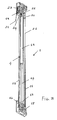
Figure 1 is a longitudinally cross-sectioned side elevation view showing a furniture piece wing including a wing driving device according to the present invention, the wing being shown an open position thereof; -
Figure 2 is a view similar tofigure 1 , but with the wing shown in a closed position thereof; -
Figure 3 is a perspective view showing a piston, wheel bearing and transmission plate assembly included in the wing driving device according to the invention; -
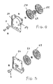
Figure 4 is an exploded perspective view of a fixed plate assembly included in the wing driving device according to the present invention;
and -
Figure 5 is a further exploded perspective view of a movable plate assembly included in the wing driving device according to the invention. - With reference to the number references of the above mentioned figures, the furniture piece wing driving device according to the present invention, has been generally indicated by the
reference number 1 and is applied at the side walls of furniture pieces designed for including at least a verticallyslidable wing 3 therein. - More specifically, the device according to the present invention, which essentially constitutes a hoist structure adapted to balance the weight of the
wing 3, comprises atransmission assembly 11, which, at a bottom portion thereof, is associated with thewing 3, and agas spring 4 having its end portions respectively coupled to a movablewheel bearing plate 16 and a fixedwheel bearing plate 20. - Said
spring gas spring 4 comprises apneumatic piston 15 having apiston rod 14 to the bottom free end portion thereof 13 said movablewheel bearing plate 16 is coupled. - Said movable
wheel bearing plate 16, in particular, comprises a plate-like element supporting two bottomcoaxial pulleys driving cable 21 thereon. - Said bottom
coaxial pulleys pin 6 integral or rigid with saidplate 16. - At the top thereof, said
piston 15 is operatively coupled to the fixedwheel bearing plate 20 which supports two topcoaxial pulleys sheave 19 for entraining saidoperating cable 21 thereon. - Said top
coaxial pulleys wheel bearing plate 20. - Said fixed
wheel bearing plate 20 comprises moreover an anchoringdetent element 24 for a fixed end portion of saiddriving cable 21. - The other end portion of the
cable 21 is applied to an element affixed to thewing 3, preferably to thetransmission assembly 11 integral with saidwing 3. - The arrangement of the transmission pulleys of the above disclosed hoist structure of the
inventive device 1 is such that the lengths or portions of thecable 21 between a pulley and a following pulley are substantially parallel to the movement of the wing, and, accordingly, being substantially vertical, without inclinations, thereby limiting a far as possible operating forces in a direction perpendicular to the wing movement. - An important advantage of the hoist structure according to the present invention is constituted by the coaxial arrangement of the transmission pulleys and by the fact that said transmission pulleys have a comparatively large diameter so designed as to assure a bending radius of the
cable 21 so large as to greatly reduce any torsional efforts or strain on said cable thereby providing a satisfactory sliding movement thereof. - Thus, the driving device has a smoother movement and the components thereof are subjected to a minimum wear.
- The sliding movement can be applied to an inner surface of a furniture piece wall, or it can be left exposed to the view on the front of the furniture piece wall or can also be used as a replacement therefor,
- It has been found that the invention fully achieves the intended aim and objects.
- In fact, the invention provides a furniture piece driving device which has a very strong and simple construction, allowing to provide a reliable operation in the time.
- In practicing the invention, the used materials, as well as the contingent size and shapes, can be any, depending on requirements.
Claims (10)
- A device for vertically driving furniture piece wings, characterized in that said device comprises a multiple hoist structure associated with a body of a furniture piece including at least a vertically movable wing, said structure comprising a gas spring associated, at a top portion thereof, with a fixed wheel bearing plate, integral with a holding body and, at a bottom portion thereof, with a movable wheel bearing plate for entraining a driving cable thereon, said driving cable having an end portion integral with said wing and another portion thereof integral with the fixed wheel bearing plate, said fixed and movable wheel bearing plates having each at least two coaxial pulleys for entraining said cable thereon.
- A device for vertically driving furniture piece wings, according to claim 1, characterized in that said gas spring comprises a pneumatic piston having a piston rod including a free end portion to which said movable wheel bearing plate is applied, said piston having a piston body associated with said fixed wheel bearing plate.
- A device for vertically driving furniture piece wings, according to claim 1, characterized in that said movable wheel bearing plate comprises a plate element supporting two bottom coaxial pulleys for entraining said cable thereon, said bottom coaxial pulleys being supported by a single supporting pin integral with said movable plate.
- A device for vertically driving furniture piece wings, according to claim 1, characterized in that said fixed wheel bearing plate supports two coaxial top pulleys and a sheath element for entraining said cable thereon, said top coaxial pulleys being supported by a single supporting pin integral with said fixed plate.
- A device for vertically driving furniture piece wings, according to claim 1, characterized in that said fixed wheel bearing plate supports two top coaxial pulleys and a respective sheave element for entraining said cable thereon, said top coaxial pulley being supported by a single supporting pin integral with said fixed plate, said fixed wheel bearing plate comprising moreover an anchoring detent element for a fixed end portion of said cable.
- A device for vertically driving furniture piece wings, according to claim 1, characterized in that the end portion of said cable integral with said wing is applied to a transmission assembly associated with said wing.
- A device for vertically driving furniture piece wings, according to claim 1, characterized in that said hoist structure transmission pulleys are so arranged that the cable lengths between a pulley and a following pulley are substantially parallel to the movement of the wing, that is substantially vertical, without inclinations, thereby limiting as far as possible forces operating in a direction perpendicular to the wing movement.
- A device for vertically driving furniture piece wings, according to claim 1, characterized in that the coaxial arrangement of said transmission pulleys and the diameter of said transmission pulleys provide a cable bending radius so large as to reduce to a minimum the torsional efforts on said cable while allowing said cable to smoothly slide.
- A device for vertically driving furniture piece wings, according to claim 1, characterized in that said device has a smooth operating movement, thereby the components of said device are subjected to a very low wear.
- A device for vertically driving furniture piece wings, according to claim 1, characterized in that said device is adapted to be applied to an inner surface of a furniture piece wall, or to be left exposed to the view applied on the front portion of said furniture piece or used as a replacement thereof.
Applications Claiming Priority (1)
| Application Number | Priority Date | Filing Date | Title |
|---|---|---|---|
| IT002001A ITMI20082001A1 (en) | 2008-11-11 | 2008-11-11 | DEVICE FOR VERTICAL HANDLING OF FURNITURE DOORS. |
Publications (1)
| Publication Number | Publication Date |
|---|---|
| EP2184430A1 true EP2184430A1 (en) | 2010-05-12 |
Family
ID=41165622
Family Applications (1)
| Application Number | Title | Priority Date | Filing Date |
|---|---|---|---|
| EP09174083A Withdrawn EP2184430A1 (en) | 2008-11-11 | 2009-10-26 | A device for vertically driving furniture piece wings |
Country Status (2)
| Country | Link |
|---|---|
| EP (1) | EP2184430A1 (en) |
| IT (1) | ITMI20082001A1 (en) |
Cited By (2)
| Publication number | Priority date | Publication date | Assignee | Title |
|---|---|---|---|---|
| WO2015128525A1 (en) * | 2014-02-25 | 2015-09-03 | Arcoiza Lopez Roberto | Drop-down screen |
| WO2019197944A1 (en) * | 2018-04-11 | 2019-10-17 | Valcucine S.P.A. | Furnishing element comprising doors |
Citations (2)
| Publication number | Priority date | Publication date | Assignee | Title |
|---|---|---|---|---|
| US4642845A (en) | 1985-07-08 | 1987-02-17 | The Celotex Corporation | Balance assembly for a window |
| EP0953713A2 (en) | 1998-04-28 | 1999-11-03 | Arturo Salice S.p.A. | Closure for openings of all kinds, especially for furniture |
-
2008
- 2008-11-11 IT IT002001A patent/ITMI20082001A1/en unknown
-
2009
- 2009-10-26 EP EP09174083A patent/EP2184430A1/en not_active Withdrawn
Patent Citations (2)
| Publication number | Priority date | Publication date | Assignee | Title |
|---|---|---|---|---|
| US4642845A (en) | 1985-07-08 | 1987-02-17 | The Celotex Corporation | Balance assembly for a window |
| EP0953713A2 (en) | 1998-04-28 | 1999-11-03 | Arturo Salice S.p.A. | Closure for openings of all kinds, especially for furniture |
Cited By (3)
| Publication number | Priority date | Publication date | Assignee | Title |
|---|---|---|---|---|
| WO2015128525A1 (en) * | 2014-02-25 | 2015-09-03 | Arcoiza Lopez Roberto | Drop-down screen |
| EP3056641A4 (en) * | 2014-02-25 | 2017-06-14 | Arcoiza Lopez, Roberto | Drop-down screen |
| WO2019197944A1 (en) * | 2018-04-11 | 2019-10-17 | Valcucine S.P.A. | Furnishing element comprising doors |
Also Published As
| Publication number | Publication date |
|---|---|
| ITMI20082001A1 (en) | 2010-05-12 |
Similar Documents
| Publication | Publication Date | Title |
|---|---|---|
| US8177174B2 (en) | Monitor lift mechanism | |
| JP4253034B1 (en) | Automatic door opening / closing device | |
| CN105901942B (en) | Self-powered platform | |
| US20160089996A1 (en) | Charging stand | |
| EP2840283A1 (en) | Rotating member for an elevating device | |
| EP2108755A3 (en) | Wall panel system including a retractable floor anchor. | |
| EP1764557A2 (en) | Compact hinge device for a door | |
| EP2184430A1 (en) | A device for vertically driving furniture piece wings | |
| JP2017533772A (en) | Damping or return device for sliding door doors or drawers | |
| US20110042634A1 (en) | Tether hoist systems and apparatuses | |
| US11603693B2 (en) | Furniture hinge for upward-opening cabinet doors | |
| EP2083143B1 (en) | Device for vertically driving furniture piece wings | |
| US9518418B2 (en) | Assembly for opening/closing of wings through synchronized motion | |
| EP2165925A3 (en) | Cable operating mechanism | |
| EP2918759A3 (en) | Door closing and securing mechanism | |
| EP2472036A3 (en) | Hydraulic mechanism for door opening | |
| EP1790879A3 (en) | Manual transmission | |
| CN204534022U (en) | A kind of display device dragline type lifting support frame | |
| CN110301770A (en) | One kind suppressing pull back actuator and sliding rail | |
| EP1402809A3 (en) | Device for balancing the door of a dishwasher appliance | |
| CN108368719A (en) | Lifting system for sliding flabellum | |
| EP0919776A2 (en) | Hinge device, particularly for the door of household electric appliances and the like with counterbalancing and self-regulating means | |
| EP2389837A1 (en) | Elastic force adjustment device for slide assembly | |
| JP2016146997A (en) | Storage system | |
| CN209381868U (en) | A kind of fire-retardant Gas assisted injection moulding handle of automobile roof |
Legal Events
| Date | Code | Title | Description |
|---|---|---|---|
| PUAI | Public reference made under article 153(3) epc to a published international application that has entered the european phase |
Free format text: ORIGINAL CODE: 0009012 |
|
| AK | Designated contracting states |
Kind code of ref document: A1 Designated state(s): AT BE BG CH CY CZ DE DK EE ES FI FR GB GR HR HU IE IS IT LI LT LU LV MC MK MT NL NO PL PT RO SE SI SK SM TR |
|
| 17P | Request for examination filed |
Effective date: 20101109 |
|
| 17Q | First examination report despatched |
Effective date: 20101202 |
|
| STAA | Information on the status of an ep patent application or granted ep patent |
Free format text: STATUS: THE APPLICATION IS DEEMED TO BE WITHDRAWN |
|
| 18D | Application deemed to be withdrawn |
Effective date: 20120712 |