EP2183861B1 - Kommunikationssystem mit mimo-basierter netzwerkcodierung - Google Patents
Kommunikationssystem mit mimo-basierter netzwerkcodierung Download PDFInfo
- Publication number
- EP2183861B1 EP2183861B1 EP08800242.3A EP08800242A EP2183861B1 EP 2183861 B1 EP2183861 B1 EP 2183861B1 EP 08800242 A EP08800242 A EP 08800242A EP 2183861 B1 EP2183861 B1 EP 2183861B1
- Authority
- EP
- European Patent Office
- Prior art keywords
- node
- data
- network
- network coding
- queue
- Prior art date
- Legal status (The legal status is an assumption and is not a legal conclusion. Google has not performed a legal analysis and makes no representation as to the accuracy of the status listed.)
- Not-in-force
Links
Images


Classifications
-
- H—ELECTRICITY
- H04—ELECTRIC COMMUNICATION TECHNIQUE
- H04B—TRANSMISSION
- H04B7/00—Radio transmission systems, i.e. using radiation field
- H04B7/02—Diversity systems; Multi-antenna system, i.e. transmission or reception using multiple antennas
- H04B7/04—Diversity systems; Multi-antenna system, i.e. transmission or reception using multiple antennas using two or more spaced independent antennas
- H04B7/0413—MIMO systems
- H04B7/0456—Selection of precoding matrices or codebooks, e.g. using matrices antenna weighting
-
- H—ELECTRICITY
- H04—ELECTRIC COMMUNICATION TECHNIQUE
- H04B—TRANSMISSION
- H04B7/00—Radio transmission systems, i.e. using radiation field
- H04B7/02—Diversity systems; Multi-antenna system, i.e. transmission or reception using multiple antennas
- H04B7/04—Diversity systems; Multi-antenna system, i.e. transmission or reception using multiple antennas using two or more spaced independent antennas
- H04B7/0413—MIMO systems
- H04B7/0452—Multi-user MIMO systems
-
- H—ELECTRICITY
- H04—ELECTRIC COMMUNICATION TECHNIQUE
- H04B—TRANSMISSION
- H04B7/00—Radio transmission systems, i.e. using radiation field
- H04B7/02—Diversity systems; Multi-antenna system, i.e. transmission or reception using multiple antennas
- H04B7/04—Diversity systems; Multi-antenna system, i.e. transmission or reception using multiple antennas using two or more spaced independent antennas
- H04B7/06—Diversity systems; Multi-antenna system, i.e. transmission or reception using multiple antennas using two or more spaced independent antennas at the transmitting station
- H04B7/0697—Diversity systems; Multi-antenna system, i.e. transmission or reception using multiple antennas using two or more spaced independent antennas at the transmitting station using spatial multiplexing
-
- H—ELECTRICITY
- H04—ELECTRIC COMMUNICATION TECHNIQUE
- H04B—TRANSMISSION
- H04B7/00—Radio transmission systems, i.e. using radiation field
- H04B7/02—Diversity systems; Multi-antenna system, i.e. transmission or reception using multiple antennas
- H04B7/022—Site diversity; Macro-diversity
- H04B7/026—Co-operative diversity, e.g. using fixed or mobile stations as relays
-
- H—ELECTRICITY
- H04—ELECTRIC COMMUNICATION TECHNIQUE
- H04B—TRANSMISSION
- H04B7/00—Radio transmission systems, i.e. using radiation field
- H04B7/14—Relay systems
- H04B7/15—Active relay systems
- H04B7/155—Ground-based stations
- H04B7/15521—Ground-based stations combining by calculations packets received from different stations before transmitting the combined packets as part of network coding
-
- H—ELECTRICITY
- H04—ELECTRIC COMMUNICATION TECHNIQUE
- H04L—TRANSMISSION OF DIGITAL INFORMATION, e.g. TELEGRAPHIC COMMUNICATION
- H04L1/00—Arrangements for detecting or preventing errors in the information received
- H04L1/004—Arrangements for detecting or preventing errors in the information received by using forward error control
- H04L1/0076—Distributed coding, e.g. network coding, involving channel coding
-
- H—ELECTRICITY
- H04—ELECTRIC COMMUNICATION TECHNIQUE
- H04L—TRANSMISSION OF DIGITAL INFORMATION, e.g. TELEGRAPHIC COMMUNICATION
- H04L1/00—Arrangements for detecting or preventing errors in the information received
- H04L1/12—Arrangements for detecting or preventing errors in the information received by using return channel
- H04L1/16—Arrangements for detecting or preventing errors in the information received by using return channel in which the return channel carries supervisory signals, e.g. repetition request signals
- H04L1/18—Automatic repetition systems, e.g. Van Duuren systems
- H04L1/1812—Hybrid protocols; Hybrid automatic repeat request [HARQ]
Definitions
- the present invention relates to wireless communication systems. More specifically, the present invention relates to network coding schemes for wireless communication systems.
- Network coding increases the capacity or throughput of a wireless network by mixing information received from source nodes at an intermediate node, and retransmitting the mixed information to one or more destination nodes.
- the content of any information flowing out of the intermediate node can be derived by the destination nodes from the information which flowed into the intermediate node.
- the combination of network coding and wireless broadcasting can increase unicast throughput of bidirectional traffic using decoding techniques well known in the art.
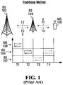
- FIG. 1 illustrates a conventional method (i.e. without network coding) of information exchange between a Base Station (BS) 102 and a Mobile Station (MS) 106 using a Relay Station (RS) 104.
- MS 106 forwards packet "a" destined for BS 102. Since BS 102 is out of range, RS 104 intercepts packet "a" and relays it to BS 102 at time slot T2.
- BS 102 forwards packet "b" to MS 106 in return, which is also intercepted and relayed via RS 104 at T4.
- Figure 2 illustrates an information exchange between BS 102 and MS 106, but in this scenario RS 104 employs conventional network coding.
- the intermediate node i.e. RS 1014 encodes and multicasts the information received from the source nodes (i.e. BS 102 and MS 106).
- MS 106 forwards packet "a" to RS 104.
- BS 102 forwards packet "b" to RS 104.
- RS 104 multicasts a mixture of packets "a + b" (where "+” refers to binary XOR encoding) to both BS 102 and MS 106. Accordingly, it takes three time slots to complete the information exchange.
- the scenario in Figure 2 illustrates a Single-Input-Single-Output (SISO) antenna system, a BS-RS-MS scenario and equal time slot scheduling.
- SISO Single-Input-Single-Output
- a multiple-input, multiple-output (MIMO) wireless communication system has multiple communication channels that are used between a plurality of antennas at a transmitter and a receiver. Accordingly, in a MIMO system a transmitting device will have N transmit antennas, and a receiving device will have M receive antennas. Space-time coding controls what data is transmitted from each of the N transmit antennas. A space-time encoding function at the transmitter processes data to be transmitted and creates unique information to transmit from the N transmit antennas. Each of the M receive antennas will receive signals transmitted from each of the N transmit antennas. A space-time decoding function at the receiving device will combine the information sent from the N transmit antennas to recover the data.
- MIMO multiple-input, multiple-output
- Adaptive virtual MIMO refers to a hybrid/combination of pure virtual MIMO and non-virtual MIMO and therefore includes virtual MIMO as a special case. More particularly, adaptive virtual MIMO means virtual MIMO, single input multiple output (SIMO), or a combination of virtual MIMO and SIMO.
- SIMO single input multiple output
- US 2007/149117 A1 discloses a method and system for transmitting and receiving signals to increase transmission efficiency in a wireless communication system using multiple antennas.
- a relay node receives a first signal from a base station according to a first signal scheme and a second signal from a mobile station according to a second signal scheme.
- the relay node generates a third signal by XOR-operating the first signal and the second signal, multiplies the third signal by a weight matrix, and transmits the multiplied signal to the base station and the mobile station.
- Darmawan A. et al. "Amplify-and-forward scheme in cooperative spatial multiplexing", 16th IST mobile and wireless communications summit 2007, 1 July 2007, pages 1-5 , discloses an amplify-and-forward cooperative spatial multiplexing scheme in which the transmitter (source), equipped with a single antenna, forms virtual antenna array from a collection of distributed single-antenna wireless terminals, and broadcasts identical signal to those terminals (relays).
- the receiver nulls and cancels the interference from different relays in order of the signal-to-noise ratio, and detects the original signal transmitted from the source.
- the system and method described herein employs adaptive virtual MIMO for unicast transmissions, MIMO based network encoding, and multiuser MIMO for multicast transmissions.
- Adaptive virtual MIMO refers to one or multiple mobile stations transmitting at one or multiple resource units.
- the network encoding scheme employed is one of Decode and Forward (DF), Map and Forward (MF) and Amplify and Forward (AF).
- DF Decode and Forward
- MF Map and Forward
- AF Amplify and Forward
- multiuser MIMO multicast transmissions use one of space-time block code (STC) and beamforming.
- STC space-time block code
- beamforming beamforming
- MIMO based network encoding is performed at a lower physical layer using one of MF and AF encoding schemes.
- a simplified scheduler is employed for more flexible and simpler resource allocation.
- more application scenarios can be accommodated than those illustrated in Figures 1 and 2 (i.e. BS-RS-MS).
- Some of these scenarios include MS-BS-MS, RS-BS-RS, MS-BS-RS, BS-RS-RS, BS-RS-MS, BS-MS-MS, and RS-MS-MS.
- MSs When MSs are near each other, they can form a group, and this will be treated as an MS Group (MSG).
- MSs MSs are near each other, they can form a group, and this will be treated as an MS Group (MSG).
- Some of these scenarios include MSG-BS-MSG, MSG-BS-RS, BS-RS-MSG, BS-MSG-MSG, and RS-MSG-MSG.
- an intermediate station such as a RS receives adaptive virtual MIMO transmissions, applies MIMO based network coding to the received information, and transmits an encoded Hybrid Automatic Repeat Request (HARQ) message via uplink to a serving station.
- HARQ Hybrid Automatic Repeat Request
- a wireless communication system including an intermediate node, a first node and a second node, the intermediate node including a plurality of antennas, a method for implementing MIMO based network coding comprising: the first node transmitting first data to the intermediate node, and the second node transmitting second data to the intermediate node; the intermediate node receiving the transmissions from both first node and second node, and performing network coding on the first data and second data using a predefined network coding scheme to produce network coded information; the intermediate node transmitting the network coded information to the first node and second node using multi-user MIMO; and; both first node and second node receiving the MIMO transmission and applying network decoding to recover the first data and second data.
- the first peer node may belong to a group of peer nodes all within a same coverage area.
- the second peer node may belong to a group of peer node all within a same coverage area.
- a transceiver in a wireless communications network for implementing MIMO based network coding, comprising: a plurality of antennas; circuitry operable to receive first data from a first node, and second data from a second node; perform network coding on the first data and second data using a predefined network coding scheme to produce network coded information; and transmit the network coded information to the first node and second node using multi-user MIMO.
- MIMO based network coding includes:
- Figure 3 is a flowchart of steps in one embodiment of MIMO based network coding.
- Figure 3 is intended to provide a high level summary of the various steps which may be involved in connection with each of the various embodiments described herein.
- Figure 4A is a schematic diagram of a wireless communications environment according to one embodiment involving the use of a DF network coding scheme.
- the general architecture framework of MIMO based network coding allows for the performance of different levels of network coding, including network coding at the binary bit level, finite field arithmetic level, modulation symbol level, and signaling waveform level.
- Various MIMO technologies can be employed, including adaptive virtual MIMO, STC and beamforming.
- the architecture is also suitable for different air-interfaces including Orthogonal Frequency Division Multiplexing (OFDM), Time Division Multiple Access (TDMA), and Code Division Multiple Access (CDMA).
- OFDM Orthogonal Frequency Division Multiplexing
- TDMA Time Division Multiple Access
- CDMA Code Division Multiple Access
- Scheduling step 302 relates to the scheduling and queuing of packets at intermediate network encoding nodes, such as BS 402 shown in Figure 4A .
- Scheduling step 302 is performed by a scheduler which can contribute to maximizing the gain from the use of MIMO based network coding. Scheduling step 302 will be described in more detail in conjunction with one embodiment of the scheduler illustrated in Figure 10 below.
- pre-processing is performed at peer nodes 404, 406. Further details concerning the pre-processing step will be provided in connection with Figure 7 .
- virtual MIMO can be used to uplink packet "a" from MS A 404 to BS 402.
- Virtual MIMO can also used to uplink packet "b" from MS B 406 to BS 402.
- both peer nodes can transmit to the intermediate network encoding node using the same resource unit.
- MMSE Minimum Mean Square Error
- MMSE-SIC MMSE-soft interference calculation
- network coding is performed at the network encoding node, which in Figure 4 is BS 402.
- network coding comprises a binary (or finite field arithmetic) linear combination.
- BS 402 multicasts a+b to both MS A 404 and MS B 406 simultaneously via downlink MIMO transmissions (e.g., STC or beamforming).
- downlink MIMO transmissions e.g., STC or beamforming.
- Figure 4B is a schematic diagram illustrating the processing of bits between the network layer and the physical layer using the DF network coding scheme illustrated in Figure 4A .
- Figure 4C is a table indicating the values of the various variables as they pass through the various processing stages of this embodiment.
- Both MS A 404 and MS B 406 pass the information bits from the network layer to the physical layer, transfer the information into a proper modulation symbol, and transmit to BS 402 via resource unit #1.
- BPSK Binary Phase Shift Keying
- BS 402 employs a MIMO demodulator and Forward Error Control (FEC) decoder to estimate the information bits, i.e., b ⁇ A and b ⁇ B , and passes them up to the network layer.
- FEC Forward Error Control
- a similar analysis can be performed in connection with rows 2, 3 and 4 of the table in Figure 4C .
- MS A 404 and MS B 406 first decode the network coded packet, and then extract the desired information through a linear operation (e.g. XOR) with its own transmitted information, i.e. MS A 404 uses its knowledge of packet "a" to decode the transmission from BS 402 and calculate packet "b". Likewise, MS B 406 uses its knowledge of packet "b" to decode the transmission from BS 402 to calculate packet "a”.
- a linear operation e.g. XOR
- the advantage of the scenario illustrated in Figure 4A is that only one resource unit in uplink via virtual MIMO is used and only one resource unit in downlink via network coding is used.
- Figure 5A is a schematic diagram of a wireless communications environment according to one embodiment involving the use of a MF network coding scheme.
- pre-processing is performed at peer nodes 504, 506.
- both peer nodes perform predistortion (e.g. phase rotation and power control) and use the same Modulation and Coding Scheme (MCS).
- MCS Modulation and Coding Scheme
- virtual MIMO can be used to uplink packet "a" from MS A 504 to BS 502.
- Virtual MIMO can also used to uplink packet "b" from MS B 506 to BS 502. This step can be performed simultaneously, i.e. the same resource unit is used.
- step 308 network coding is performed at BS 502.
- BS 502 maps incoming symbols "a" and "b” into a valid symbol-level constellation according to the decision region. This is illustrated in Figure 5B .
- BS 502 uses downlink MIMO transmission to multicast a MF b MF to both MS A 504 and MS B 506 simultaneously using, for example, STC or beamforming.
- MS A 504 and MS B 506 first decode the network coded packet, and then extract the desired information through a linear operation (e.g. XOR) with its own transmitted information, i.e. MS A 504 uses its knowledge of packet "a" to decode the transmission from BS 502 and calculate packet "b". Likewise, MS B 506 uses its knowledge of packet "b" to decode the transmission from BS 502 to calculate packet "a”.
- a linear operation e.g. XOR
- the advantage of the scenario illustrated in Figure 5A is that only one resource unit in uplink via virtual MIMO is used, and only one resource unit in downlink via network coding is used. As well, there is no decoding process required at the intermediate nodes.
- Figure 5B is a schematic diagram illustrating the processing of bits between the network layer and the physical layer using the MF network coding scheme illustrated in Figure 5A .
- Figure 5C is a table indicating the values of the various variables as they pass through the various processing stages of this embodiment.
- Both MS A 504 and MS B 506 pass the information bits from the network layer to the physical layer, transfer the information into a proper modulation symbol, and transmit to BS 502 via resource unit #1.
- BS 502 employs a MIMO demodulator (without FEC decoder) and maps the received signal into a valid modulation symbol x MF at the physical layer.
- An example of mapping rule (or called MF decision region for BPSK) is illustrated in the bottom of Figure 5B .
- MF decision region for BPSK
- Next BS 502 multicasts x MF to both MS A 504 and MS B 506 via resource unit #2.
- Figure 6A is a schematic diagram of a wireless communications environment according to one embodiment involving the use of an AF network coding scheme.
- pre-processing is performed at peer nodes 604, 606.
- virtual MIMO can be used to uplink packet "a" from MS A 604 to BS 602.
- Virtual MIMO can also used to uplink packet "b" from MS B 606 to BS 602. This step can be performed simultaneously, i.e. the same resource unit is used.
- network coding is performed at BS 602.
- BS 602 amplifies the incoming MIMO signals (waveform level). This is illustrated in Figure 6B .
- BS 602 uses downlink MIMO transmission to multicast a AF b AF to both MS A 604 and MS B 606 simultaneously using, for example, STC or beamforming.
- each of MS A 604 and MS B 606 first subtracts its own information, and then decodes the subtracted packet to obtain the desired information, i.e. MS A 604 uses its knowledge of packet a to decode the transmission from BS 602 and calculate packet "b". Likewise, MS B 606 uses its knowledge of packet b to decode the transmission from BS 602 to calculate packet "a".
- the advantage of the scenario illustrated in Figure 6A is that only one resource unit in uplink via virtual MIMO is used and only one resource unit in downlink via network coding is used. As well, there is no decoding process required at the peer nodes, and no demodulation process.
- Figure 6B is a schematic diagram illustrating the processing of bits between the network layer and the physical layer using the AF network coding scheme illustrated in Figure 6A .
- Figure 6C is a table indicating the values of the various variables as they pass through the various processing stages of this embodiment.
- Both MS A 604 and MS B 606 pass the information bits from the network layer to the physical layer, transfer the information into proper modulation symbol, and transmit to BS 602 via resource unit #1.
- BS 602 multiplies the received signal y BS by a factor of beta, and obtains signal x AF . Note, there is no need for a MIMO demodulator and a FEC decoder.
- BS 602 multicasts x AF to both MS A 604 and MS B 606 via resource unit #2.
- Figures 4A, 4B , 4C , 5A, 5B , 5C , 6A, 6B , and 6C each provide a specific example of a communication system or elements of a communication system that could be used to implement embodiments of the invention. It is to be understood that embodiments of the invention can be implemented with communications systems having architectures that are different than the specific examples described herein, but that operate in a manner consistent with the implementation of the embodiments as described herein.
- the network encoding node can be a RS node or a BS node, or a MS node
- the network decoding node can be a MS node, a RS node, or a BS node.
- the network coding configurations can be MS-BS-MS, MS-RS-MS, MS-BS-RS, RS-BS-RS, BS-RS-RS, BS-MS-MS, RS-MS-MS, MSG-BS-MSG (MS group), MSG-RS-MSG, BS-MSG-MSG, RS-MSG-MSG, and MSG-BS-RS.
- the network paths can be constituted by the individual or combination of basic configurations of network coding configurations mentioned above.
- the network can be configured by individual or combination of basic configurations of the network coding configurations and/or network paths mentioned above.
- the network can utilize a Point to Multipoint (PMP) or mesh topology.
- MP Point to Multipoint
- FIG. 7 is a flowchart of a MIMO based network coding architecture with additional detail concerning the pre-processing step. Steps 302, 306, 308, 310 and 312 are carried out in the same manner as discussed above in connection with Figure 3 . In Figure 7 , further detail is only provided in respect of pre-processing step 304.
- pre-processing of information bits is carried out as follows.
- the information bits are packed, and at step 704 the Medium Access Control (MAC) header and Cyclic Redundancy Check (CRC) are added.
- MAC Medium Access Control
- CRC Cyclic Redundancy Check
- forward error control code e.g., convolution code, Turbo code, Low Density Parity-Check Code (LDPC)
- LDPC Low Density Parity-Check Code
- the resulting information is mapped to modulation symbols (e.g., Quadrature Phase Shift Keying (QPSK), 16 Quadrature Amplitude Modulation (QAM), 64QAM).
- QPSK Quadrature Phase Shift Keying
- QAM 16 Quadrature Amplitude Modulation
- 64QAM 64QAM
- step 714 If yes, apply predistortion (e.g., constellation rotation and/or power control) and proceed to step 714, otherwise proceed directly to step 714 where the base-band modulation symbols are transformed to pass-band waveform signals. Then proceed to the uplink adaptive virtual MIMO transmissions step 306 described above in connection with Figure 3 .
- predistortion e.g., constellation rotation and/or power control
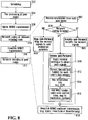
- FIG 8 is a flowchart of a MIMO based network coding architecture with additional detail concerning the network coding and downlink steps. Steps 302, 304, 306, and 312 are carried out in the same manner as discussed above in connection with Figure 3 . In Figure 8 , further detail is only provided in respect of the network coding step 308 and the downlink step 310.
- the intermediate node receives the information/signals from both peer nodes.
- a check is performed of which network coding scheme is being used. If the network coding scheme is MF, proceed to step 806. If the network coding scheme is AF, proceed to step 808. If the network coding scheme is DF, proceed to step 810.
- step 806 i.e. the network coding scheme is MF
- step 818 map the received signals to valid modulation symbols according to a predetermined decision-region, which depends on the predistortion process at step 712. Proceed to step 818.
- step 808 i.e. the network coding scheme is AF
- step 810 i.e. the network coding scheme is DF
- apply one of the receiver techniques e.g., Zend Framework (ZF), MMSE, MMSE-SIC
- ZF Zend Framework
- MMSE MMSE-SIC
- step 812 for each peer node's data stream, conduct demodulation, decoding, de-MAC to obtain the information bits.
- step 814 network encode the information bits from both peer nodes by XOR (or other finite field arithmetic) operation. If the packet sizes from both peers are different, simply pad zeros for the shorter packet before network encoding.
- step 816 add MAC header, apply FEC code, and apply modulation constellation. Proceed to step 818.
- step 818 transform the base-band signals to pass-band signals, and multicast the signals from the network encoding node to both peer nodes via downlink MIMO transmissions (e.g., STC or beamforming). Then proceed to network decoding step 312 which is described above in connection with Figure 3 . More detail concerning the network decoding step is provided in connection with Figure 9 below.
- downlink MIMO transmissions e.g., STC or beamforming
- FIG 9 is a flowchart of a MIMO based network coding architecture with additional detail concerning the network decoding step. Steps 302, 304, 306, 308 and 310 are carried out in the same manner as discussed above in connection with Figure 3 . In Figure 9 , further detail is only provided in respect of network decoding step 312.
- each peer node receives the multicast signals.
- a check is performed of which network coding scheme is being used. If the network coding scheme is MF or DF, proceed to step 906. If the network coding scheme is AF, proceed to step 914.
- step 906 demodulate the signals into valid modulation symbols.
- step 908 apply FEC code decoding process.
- de-MAC header (and check CRC) to obtain (network coded) information bits.
- step 912 perform network decoding by mixing the received (network coded) information bits with the transmitted information bits via XOR (or other finite-field arithmetic) operation, and hence obtain the desired information bits.
- a joint process of demodulation 906, decode 908, network decoding 912, and deMAC 910 can also be conducted in an iterative manner. Proceed to step 922.
- step 914 i.e. the network coding scheme is AF
- step 916 demodulate the subtracted signals into valid modulation symbols.
- step 918 apply forward error control code decoding process.
- step 920 de-MAC header (and check CRC) to obtain desired information bits. Proceed to step 922.
- step 922 deliver the desired information bits to upper layers.
- Figure 10 is a schematic diagram of a scheduler used in connection with some embodiments of the invention.
- BS 1000 having a set of antennas 1004, 1006.
- BS 1000 is shown in wireless communication with MS A 1008 and MS B 1010. Note that BS 1000 can be connected to any network or portion of a network from which/over which packets 1012 are delivered to/from base station 1000. Also shown is UL and DL switch 1014 which is used to transport packets to (in the downlink direction) and from (in the uplink direction) BS 1000.
- network code encoder 1016 for DF used to encode packets received from either virtual queue A 1018 (i.e. queue of packets from MS A 1008) or virtual queue B 1020 (i.e. the queue of packets from MS B 1008).
- packets 1012 are transported to UL and DL switch 1014 for transmitting to MS 1008 and MS B 1010 in the manner described above.
- BS 1000 also includes a MIMO-based network coding scheduler 1002.
- MIMO-based network coding scheduler 1002 selects packets for transmission among the packets in either virtual queue A 1018 or virtual queue B 1020.
- MIMO-based network coding scheduler 1002 is used to increase network coding gain that would otherwise not be realized.
- MIMO based network coding scheduler 1002 arranges for a flexible resource allocation for uplink and downlink.
- resource unit is defined as follows: (i) time-frequency sub-channels for OFDM, (ii) time slots for TDMA; and (iii) orthogonal codes for CDMA.
- For downlink there is an allocation of resources for network encoding node to multicast, using STC and beamforming. Practical factors such as queue length and fairness are taken into account.
- packets from MS A 1008 will arrive at BS 1000 via the UL & DL Switch 1014.
- Packets from MS B 1010 (shown in dotted outline) will also arrive in the same manner.
- the packets will be transported by UL & DL Switch 1014 to MIMO-based network coding scheduler 1002 where they will enter initial virtual queue 1022 in the order in which they are received.
- the packets will then be transported from initial virtual queue 1022 to virtual queue A 1028 or virtual queue B, depending on whether the packets originated from MS A 1008 or MS B 1020.
- Network Code Encoder 1016 When both virtual queues are non-empty, Network Code Encoder 1016 encodes the packets from both queues, and delivers it to UL & DL switch 1014 for downlink multicast to both peers. In this way, network coding gain is realized, hence system performance is enhanced. When only one queue is non-empty, Network Code Encoder 1016 simply passes the packet from the non-empty queue to UL & DL switch. This is same as traditional scheduler without Network Code Encoder 1016. When both queues are empty, Network Code Encoder does nothing.
- scheduling employs a policy called Lowest Queue Highest Priority (LQHP) algorithm for uplink.
- LQHP Lowest Queue Highest Priority
- a relay network does not provide for network coding at an intermediate station (e.g. a RS or a MS.
- an intermediate station e.g. a RS or a MS.
- RS is used to refer either RS or MS in later context.
- HARQ retransmissions for different source stations e.g. mobile stations
- a serving station e.g. a BS
- the embodiments described herein use MIMO based network coding to forward network coded HARQ information to a serving station. This can increase HARQ reliability and may also reduce resource consumption.
- FIG 11 is a diagram of a wireless communications environment according to one embodiment. Shown is a cellular wireless network including a base station (BS) 1102, a relay station (RS) 1104, and two mobile stations MS1 1106 and MS2 1108.
- BS 1102 is the serving station for MS1 1106 and MS2 1108. As serving station, BS 1102 is responsible for scheduling resources for uplink transmission and HARQ retransmission, and sending Acknowledgement (ACK)/ Acknowledgement Negative (NACK) transmission as required.
- ACK Acknowledgement
- NACK Acknowledgement Negative
- Figure 11 also shows a high geometry area of BS 1102 which is marked by "H” 1110. Also shown in a medium geometry area of BS 1102 which is marked by “M” 1112, and a low geometry area of BS 1102 which is marked by “L” 1114. Finally, the coverage area of RS 1104 is marked by “C” 1116. MS1 1106 and MS2 1108 are both located in medium geometry area 1112, and within the coverage area 1116 of RS 1104.
- MSs can be dispersed throughout the coverage area of a BS or a RS.
- a first MS which is closer to a BS (for example, in a high geometry area) than a second MS (for example, in a medium geometry area) will require relatively less power to communicate with the BS in the uplink and downlink directions.
- Figure 12 is an example timing diagram for communications in accordance with the embodiment illustrated in Figure 11 .
- Figure 13 is an example flowchart for the embodiment illustrated in Figures 11 and 12 .
- BS 1102 performs scheduling by forwarding a BS control packet B-SCH to RS 1104, MS1 1106, and MS2 1108.
- both MS1 1106 and MS2 1108 multicast their packets d1, d2 to RS 1104 and BS 1102 (in this case via adaptive virtual MIMO) using the same/different resource unit.
- BS 1102 tries to decode d1 and d2 received from MS1 1106 and MS2 1108 respectively. If there has been successful decoding following a determining of success at step 1308, BS 1102 multicasts at step 1316 an ACK packet to MS 1 1106, MS2 1108 and RS 1104. The process is ended at step 1320.
- BS 1102 unicasts a NACK packet to RS 1104 at step 1314.
- RS 1104 then at step 1310 demodulates and/or decodes d1 and d2 received from MS1 1106 and MS2 1108 respectively.
- RS 1104 then performs MIMO based network coding (using any one of the network coding schemes mentioned above), and then unicasts an encoded HARQ to BS 1102.
- BS 1102 collects the received signals from step 1304 and step 1312, and conducts iterative network and channel decoding to obtain the original information d1, d2 originally transmitted from MS1 1106 and MS2 1108 respectively.
- step 1308 If there has been successful decoding following a determining of success at step 1308, BS 1102 multicasts at step 1316 an ACK packet to MS1 1106, MS2 1108 and RS 1104. Otherwise step 1314 is repeated. The process is ended at step 1320.
- Figure 14 is a diagram of a wireless communications environment according to one embodiment. Shown is a cellular wireless network including BS 1402, RS 1404, and two mobile stations MS1 1406 and MS2 1408.
- Figure 14 also shows a high geometry area of BS 1402 which is marked by "H” 1410. Also shown is a medium geometry area of BS 1402 which is marked by “M” 1412, and a low geometry area of BS 1402 which is marked by “L” 1414. Finally, the coverage area of RS 1404 is marked by “C” 1416. MS1 1406 is located in medium geometry area 1412, and MS2 1408 is located in low geometry area 1414. Both MS1 1406 and MS2 1408 are located within the coverage area 1416 of RS 1404.
- BS 1402 becomes the serving station of MS1 1406 and MS2 1408. This is called transparent mode. Otherwise, RS 1404 needs to send the synchronization and control signals to MS2 1408. In this case, BS 1402 becomes the serving station of MS1 1406, and RS 1404 becomes the serving station of MS2 1408. This is called non-transparent mode.
- a serving station (BS 1402 or RS 1404 as the case may be) is responsible for scheduling resources for uplink transmission and HARQ retransmission, and sending ACK/NACK transmissions as required.
- the synchronization and control signals of BS 1402 are able to reach the medium geometry area 1412 but not the low geometry area 1414.
- Figure 15 is an example timing diagram for communications in accordance with the embodiment illustrated in Figure 14 .
- Figure 16 is an example flowchart for the embodiment illustrated in Figures 14 and 15 . The following discussion makes reference to each of Figures 14-16 in a corresponding manner.
- BS 1402 performs scheduling by forwarding a BS control packet for resource scheduling B-SCH to RS 1404, and MS1 1406.
- RS 1404 performs scheduling by forwarding a RS control packet R-SCH for resource scheduling, or BS 1602 schedules MS2 1608 (in case of transparent mode, not expressly shown in the drawings).
- MS1 1406 multicasts d1 to BS 1402 and RS 1404, while MS2 1408 unicasts d2 to RS 1404, using the same/different resource unit.
- RS 1404 demodulates/decodes d1 and d2 received from MS1 1406 and MS2 1408 respectively. For the purpose of this description, it is assumed this step is always successful. RS 1404 then unicasts an ACK packet (in respect of d2, the information received from MS2 1408) to MS2 1408, and unicasts an ACK packet (in respect of d1, the information received from MS1 1406) to BS 1402.
- BS 1402 tries to decode d1 received from MS1 1406. If decoding is not successful, BS 1402 unicasts a NACK packet to RS 1404 and at step 1620 RS 1404 performs MIMO based joint network and channel coding (JNCC) (using any of the network coding schemes identified above) of d1 and d2 (i.e. the information transmitted from MS1 1406 and MS2 1408 respectively) and then unicasts the encoded information (or called JNCC HARQ information) to BS 1402.
- JNCC MIMO based joint network and channel coding
- BS 1402 collects the signals from steps 1606 and 1620, and conducts an iterative network and channel decoding to obtain the original information d1 from MS1 1406 and d2 from MS2 1408.
- BS 1402 multicasts an ACK packet to MS1 1406 and RS 1404 and the process concludes at step 1626. Otherwise, BS 1402 unicasts a NACK packet to RS 1404, and the process returns to step 1620.
- BS 1402 multicasts an ACK packet to MS1 1406 and RS 1404.
- RS 1404 performs channel encoding on d2 (from MS2 1408), and then unicasts the information to BS 1402.
- BS 1402 receives the information and conducts a channel decoding to obtain the original information d2 from MS2 1408. If upon determination of successful decoding at step 1618, BS 1402 multicasts an ACK packet to RS 1404, the process concludes at step 1626. Otherwise, BS 1402 unicasts a NACK packet to RS 1404, and the process returns to step 1614.
- Figure 17 is an example graph indicating network gains realized by MIMO based network coding.
- a BS in this case, either 1.4 km, 1.0 km, or 0.5 km.
- the vertical axis is the normalized throughput.
- the normalized throughput of six SISO systems is shown to be equal to 1 for comparison purposes.
- the setup used to test the gain achieved by MIMO based network coding was as follows.
- a BS was used with two antennas, and two MSs were used each with one antenna.
- Virtual MIMO was used for uplink, Space-Time Transmit Diversity (STTD) for Network Coded multicast downlink.
- STTD Space-Time Transmit Diversity
- a DF network coding scheme was employed. Equal throughput was scheduled for uplink and downlink per frame, and single cell, two MSs per drop, 1,000 realizations were used.
- the compound gain of MIMO based network coding was observed to be greater than 85%. It was also observed that in this embodiment, MIMO enhances pure network coding gain.
Landscapes
- Engineering & Computer Science (AREA)
- Computer Networks & Wireless Communication (AREA)
- Signal Processing (AREA)
- Radio Transmission System (AREA)
- Mobile Radio Communication Systems (AREA)
- Radio Relay Systems (AREA)
Claims (13)
- Verfahren zur Verwendung mit einem drahtlosen Kommunikationssystem, das einen Zwischenknoten (1000), einen ersten Knoten (1008) und einen zweiten Knoten (1010) beinhaltet, wobei das Verfahren einem Implementieren eines MIMO-basierten Netzwerk-Kodierens bei dem Zwischenknoten dient, das Verfahren umfassend:Empfangen erster Daten von dem ersten Knoten;Empfangen zweiter Daten von dem zweiten Knoten, wobei die ersten und zweiten Daten eines oder mehrere Datenpakete umfassen;Speichern der ersten Daten in einer ersten Warteschlange (1018) und Speichern der zweiten Daten in einer zweiten Warteschlange (1020);Ausführen eines Netzwerk-Kodierens (308) auf zumindest einem Teil der ersten Daten aus der ersten Warteschlange und zumindest einem Teil der zweiten Daten aus der zweiten Warteschlange unter Verwendung eines vordefinierten Netzwerk-Kodierungs-Schemas (1016) zum Erzeugen einer Netzwerk-kodierten Information (1012);Übertragen (310) der Netzwerk-kodierten Information sowohl zu dem ersten Knoten als auch zu dem zweiten Knoten unter Verwendung von Multi-user-MIMO;dadurch gekennzeichnet, dass das Verfahren umfasst
Zeitplanen (1002) von Übertragungen des einen oder der mehreren Pakete von dem ersten Knoten und dem zweiten Knoten zu dem Zwischenknoten, wobei eine höhere Priorität für das Zeitplanen für den ersten Knoten oder den zweiten Knoten eingeräumt wird basierend darauf, ob die erste Warteschlange oder die zweite Warteschlange eine kürzere Warteschlangenlänge aufweist. - Verfahren nach Anspruch 1, wobei die Multi-user-MIMO-Übertragung eine räumliche Multiplexübertragung ist.
- Verfahren nach Anspruch 1 oder 2, wobei hinsichtlich des Empfangens der ersten Daten von dem ersten Knoten (1008) und der zweiten Daten von dem zweiten Knoten (1010) die ersten Daten und die zweiten Daten zu dem Zwischenknoten übertragen werden unter Verwendung von einem oder mehreren aus räumlichem Multiplexen, Zeitmultiplexen und Frequenzmultiplexen.
- Verfahren nach Anspruch 1, 2 oder 3, wobei hinsichtlich des Empfangens der ersten Daten von dem ersten Knoten (1008) und der zweiten Daten von dem zweiten Knoten (1010) die ersten Daten und die zweiten Daten übertragen werden an den Zwischenknoten (1000) unter Verwendung von adaptivem virtuellen MIMO.
- Verfahren nach einem der Ansprüche 1 bis 4, wobei das Netzwerk-Kodieren bei dem Zwischenknoten implementiert ist durch exklusives OR- (XOR-)Operieren der ersten Daten mit den zweiten Daten.
- Verfahren nach einem der Ansprüche 1 bis 5, wobei das Netzwerk-Kodierungs-Schema, das an dem Zwischenknoten (1000) eingesetzt wird, eines ist aus Decode and Forward (DF), Map and Forward (MF) und Amplify and Forward (AF).
- Verfahren nach einem der Ansprüche 1 bis 6, wobei die Netzwerk-kodierte Information eine Hybrid Automatic Repeat Request- (HARQ-)Nachricht ist.
- Sendeempfänger (1000) in einem drahtlosen Kommunikationsnetzwerk zum Implementieren eines MIMO-basierten Netzwerk-Kodierens, wobei der Sendeempfänger umfasst:eine Vielzahl von Antennen (1004, 1006);eine Schaltung, betreibbar zum:dadurch gekennzeichnet, dass die Schaltung betreibbar ist zumEmpfangen erster Daten von einem ersten Knoten (1008) und zweiter Daten von einem zweiten Knoten (1010), wobei die ersten und die zweiten Daten eines oder mehrere Pakete umfassen;Speichern der ersten Daten in einer ersten Warteschlange (1018) und Speichern der zweiten Daten in einer zweiten Warteschlange (1020);Ausführen eines Netzwerk-Kodierens (308) auf zumindest einem Teil der ersten Daten aus der ersten Warteschlange und zumindest einem Teil der zweiten Daten aus der zweiten Warteschlange unter Verwendung eines vordefinierten Netzwerk-Kodierungs-Schemas (1016) zum Erzeugen einer Netzwerk-kodierten Information (1012);Übertragen (310) der Netzwerk-kodierten Information sowohl zu dem ersten Knoten als auch zu dem zweiten Knoten unter Verwendung von Multi-user-MIMO;
Zeitplanen (1002) von Übertragungen des einen oder der mehreren Pakete von dem ersten Knoten und dem zweiten Knoten zu dem Zwischenknoten, wobei eine höhere Priorität für das Zeitplanen für den ersten Knoten oder den zweiten Knoten eingeräumt wird basierend darauf, ob die erste Warteschlange oder die zweite Warteschlange eine kürzere Warteschlangenlänge aufweist. - Sendeempfänger nach Anspruch 8, wobei die Multi-user-MIMO-Übertragung eine räumliche Multiplexübertragung ist.
- Sendeempfänger nach Anspruch 8 oder 9, wobei hinsichtlich des Empfangens der ersten Daten von dem ersten Knoten (1008) der erste Knoten erste Daten an den Zwischenknoten (1000) überträgt, und hinsichtlich des Empfangens der zweiten Daten von dem zweiten Knoten (1010) der zweite Knoten zweite Daten an den Zwischenknoten überträgt unter Verwendung von einem oder mehreren aus räumlichem Multiplexen, Zeitmultiplexen und Frequenzmultiplexen.
- Sendeempfänger nach einem der Ansprüche 8 bis 10, wobei das Netzwerk-Kodieren implementiert ist durch exklusives OR- (XOR-)Operieren der ersten Daten mit den zweiten Daten.
- Sendeempfänger nach einem der Ansprüche 8 bis 11, wobei das Netzwerk-Kodierungs-Schema eines ist aus Decode and Forward (DF), Map and Forward (MF) und Amplify and Forward (AF).
- Sendeempfänger nach einem der Ansprüche 8 bis 12, wobei die Netzwerk-kodierte Information eine Hybrid Automatic Repeat Request- (HARQ-)Nachricht ist.
Applications Claiming Priority (3)
| Application Number | Priority Date | Filing Date | Title |
|---|---|---|---|
| US96820607P | 2007-08-27 | 2007-08-27 | |
| US98668207P | 2007-11-09 | 2007-11-09 | |
| PCT/CA2008/001511 WO2009026695A1 (en) | 2007-08-27 | 2008-08-27 | Communication system using mimo based network coding |
Publications (3)
| Publication Number | Publication Date |
|---|---|
| EP2183861A1 EP2183861A1 (de) | 2010-05-12 |
| EP2183861A4 EP2183861A4 (de) | 2014-01-15 |
| EP2183861B1 true EP2183861B1 (de) | 2017-01-25 |
Family
ID=40386614
Family Applications (1)
| Application Number | Title | Priority Date | Filing Date |
|---|---|---|---|
| EP08800242.3A Not-in-force EP2183861B1 (de) | 2007-08-27 | 2008-08-27 | Kommunikationssystem mit mimo-basierter netzwerkcodierung |
Country Status (7)
| Country | Link |
|---|---|
| US (3) | US8228835B2 (de) |
| EP (1) | EP2183861B1 (de) |
| JP (2) | JP5266450B2 (de) |
| KR (2) | KR101652608B1 (de) |
| CN (1) | CN101836369A (de) |
| BR (1) | BRPI0815891B1 (de) |
| WO (1) | WO2009026695A1 (de) |
Families Citing this family (56)
| Publication number | Priority date | Publication date | Assignee | Title |
|---|---|---|---|---|
| EP2026519A1 (de) * | 2007-08-17 | 2009-02-18 | Infineon Technologies AG | Vorverzerrung für eine Raum-Zeit-Block-Kodierung |
| US8331308B1 (en) * | 2007-11-09 | 2012-12-11 | Research In Motion Limited | Systems and methods for network MIMO |
| JP5358807B2 (ja) * | 2008-02-26 | 2013-12-04 | 横河電機株式会社 | マルチホップ無線通信システム |
| US8638811B2 (en) * | 2008-03-17 | 2014-01-28 | Qualcomm Incorporated | Reconfigurable multiple-input multiple-output systems and methods |
| KR101400715B1 (ko) * | 2008-04-02 | 2014-05-29 | 연세대학교 산학협력단 | 협력 전송 기법 및 네트워크 코딩 전송 기법을 이용한 통신장치 및 그 방법 |
| US8306095B2 (en) * | 2008-04-29 | 2012-11-06 | Samsung Electronics Co., Ltd. | Methods and apparatus for network coding in a communication system |
| US20100004016A1 (en) * | 2008-07-07 | 2010-01-07 | Hujun Yin | Power control techniques |
| KR101469856B1 (ko) * | 2008-07-10 | 2014-12-05 | 삼성전자주식회사 | 계층 변조 기법 또는 네트워크 코딩 기법을 이용하는 통신시스템 |
| US8811267B2 (en) * | 2008-08-13 | 2014-08-19 | Samsung Electronics Co., Ltd. | Communication system for supporting primary user and secondary user |
| WO2010019082A1 (en) * | 2008-08-15 | 2010-02-18 | Telefonaktiebolaget L M Ericsson (Publ) | Relay node selection for network coding |
| US8665866B2 (en) * | 2008-08-15 | 2014-03-04 | Unwired Planet, Llc | Relative time division for network coding |
| KR101543800B1 (ko) * | 2009-09-04 | 2015-08-12 | 엘지전자 주식회사 | 무선 네트워크에서 데이터 통신 방법 및 장치 |
| CN101800616B (zh) * | 2009-02-10 | 2012-11-21 | 富士通株式会社 | 数据中继装置、通信装置和方法 |
| US8737297B2 (en) * | 2009-02-20 | 2014-05-27 | Interdigital Patent Holdings, Inc. | Network coding relay operations |
| EP2427027A4 (de) * | 2009-04-28 | 2014-05-21 | Alcatel Lucent | Verfahren und vorrichtung zur assoziierten verarbeitung in einer relaisstation und entsprechende verarbeitung in einer basisstation |
| US8472357B2 (en) * | 2009-07-16 | 2013-06-25 | Futurewei Technologies, Inc. | System, methods, and apparatus for bidirectional relaying in wireless communications systems |
| CN101989900B (zh) * | 2009-08-04 | 2013-04-10 | 普天信息技术研究院有限公司 | 一种无线通信网络编码合作通信方法、非透明中继及基站 |
| EP2481164A1 (de) * | 2009-09-24 | 2012-08-01 | Universität Duisburg-Essen | Verfahren, relaisstation und system zur signalübertragung zwischen einer ersten signalquelle und einer zweiten signalquelle |
| US8908624B2 (en) * | 2009-10-22 | 2014-12-09 | Interdigital Patent Holdings, Inc. | Method and apparatus for a two-way relaying scheme with physical layer network coding |
| EP3107329B1 (de) | 2009-10-30 | 2020-05-06 | Electronics and Telecommunications Research Institute | Verfahren zur übertragung von steuerungs- und trainingssymbolen in einem mehrbenutzer-drahtloskommunikationssystem |
| US8773975B2 (en) * | 2010-01-21 | 2014-07-08 | Lg Electronics Inc. | Network coding enhancements |
| KR101730640B1 (ko) * | 2010-07-29 | 2017-05-11 | 톰슨 라이센싱 | 3노드 양방향 협력을 위한 다중 입력-다중 출력 네트워크 코딩된 증폭 및 전달 릴레이 구조 |
| EP2416518B1 (de) | 2010-08-02 | 2013-01-02 | Alcatel Lucent | Verfahren zur Übertragung von Daten in einem Funkkommunikationssystem, erster Netzwerkknoten und zweiter Netzwerkknoten dafür |
| CN101997647B (zh) * | 2010-11-02 | 2013-03-06 | 北京邮电大学 | 一种网络编码传输方法 |
| US20120120890A1 (en) * | 2010-11-12 | 2012-05-17 | Electronics And Telecommunications Research Institute | Apparatus and method for transmitting multimedia data in multimedia service providing system |
| US9077398B2 (en) | 2011-02-22 | 2015-07-07 | Nokia Technologies Oy | Network coding by beam forming |
| US8817728B2 (en) * | 2011-02-22 | 2014-08-26 | Qualcomm Incorporated | System and method for third-party assisted peer-to-peer communication |
| CN102136883B (zh) * | 2011-03-15 | 2013-05-08 | 清华大学 | 基于网络编码的协作中继传输方法 |
| EP2501055B1 (de) * | 2011-03-17 | 2013-09-25 | Alcatel Lucent | Konzept zur Bereitstellung von Datendetektionsinformationen |
| JP5739521B2 (ja) * | 2011-04-19 | 2015-06-24 | パナソニック インテレクチュアル プロパティ コーポレーション オブアメリカPanasonic Intellectual Property Corporation of America | 信号生成方法及び信号生成装置 |
| CN102148664B (zh) * | 2011-04-21 | 2013-06-05 | 上海大学 | 应用于多源多汇网络的组播间网络编码控制方法 |
| CN102244561B (zh) * | 2011-06-23 | 2013-11-06 | 西安电子科技大学 | 用于多址接入中继网络的中继传输方法 |
| KR101758845B1 (ko) * | 2012-04-02 | 2017-07-17 | 삼성전자주식회사 | 양방향 트래픽을 위한 물리 계층 네트워크 코딩에 기반한 스케줄링 방법 및 장치 |
| CN104471869B (zh) * | 2012-05-14 | 2016-07-13 | 英派尔科技开发有限公司 | 中继数据的方法、无线通信网络和中继装置 |
| CN103023628B (zh) * | 2012-12-21 | 2015-08-05 | 无锡北邮感知技术产业研究院有限公司 | 基于网络编码的中继协作harq方法 |
| WO2014100933A1 (en) * | 2012-12-24 | 2014-07-03 | Intel Corporation | Providing multiple content items for display on multiple devices |
| US9246697B2 (en) * | 2013-01-29 | 2016-01-26 | Korea Advanced Institute Of Science And Technology | Communication device, multicast control method, and scheduling control method |
| KR102053333B1 (ko) * | 2013-01-31 | 2019-12-06 | 삼성전자주식회사 | 무선 통신 시스템에서 개선된 네트워크 코딩 방법 및 장치 |
| KR102115401B1 (ko) | 2013-04-24 | 2020-05-26 | 삼성전자주식회사 | 네트워크 코딩을 지원하는 시스템에서 패킷을 관리하는 방법 및 장치 |
| KR102164708B1 (ko) * | 2014-02-19 | 2020-10-12 | 삼성전자주식회사 | 통신 방법 및 장치 |
| MX367549B (es) * | 2014-05-28 | 2019-08-27 | Ericsson Telefon Ab L M | Método para la retransmisión de datos del usuario ortogonalmente para usuarios diferentes. |
| US10153873B2 (en) * | 2014-08-20 | 2018-12-11 | Newracom, Inc. | Physical layer protocol data unit format applied with space time block coding in a high efficiency wireless LAN |
| CN104486040B (zh) * | 2014-12-15 | 2017-10-24 | 西安电子科技大学 | 基于缓存管理的高效编码感知路由方法 |
| KR102396405B1 (ko) * | 2014-12-29 | 2022-05-10 | 한국전자통신연구원 | 공간 주파수 블록 코딩 및 물리적 네트워크 코딩을 이용한 양방향 중계국 시스템 및 방법 |
| US9800311B2 (en) * | 2014-12-30 | 2017-10-24 | Electronics And Telecommunications Research Institute | Beam formation for data transmission for two-way multi-antenna relay system with physical network coding |
| EP3335345B1 (de) | 2015-11-23 | 2021-05-26 | Ozyegin Universitesi | Netzwerkzufallscodierung in ofdma-netzwerken mithilfe von steuersignalisierung |
| US9647335B1 (en) * | 2015-12-31 | 2017-05-09 | Facebook, Inc. | Joint beamforming in point-to-point wireless communication networks |
| JP6751360B2 (ja) * | 2017-01-24 | 2020-09-02 | 株式会社Kddi総合研究所 | 通信装置、制御方法、及びプログラム |
| US10349427B2 (en) | 2017-04-13 | 2019-07-09 | Kabushiki Kaisha Toshiba | Method for scheduling closed loop information in wireless networks |
| US10462808B2 (en) | 2017-04-13 | 2019-10-29 | Kabushiki Kaisha Toshiba | Method for scheduling transmissions in wireless networks |
| US10368349B2 (en) | 2017-04-13 | 2019-07-30 | Kabushiki Kaisha Toshiba | Method for assisting bidirectional communication in wireless networks |
| WO2019236476A1 (en) | 2018-06-04 | 2019-12-12 | SparkMeter, Inc. | Wireless mesh data network with increased transmission capacity |
| US10673577B2 (en) | 2018-07-24 | 2020-06-02 | Kabushiki Kaisha Toshiba | Method for efficient retransmissions in multi-hop control networks |
| US11388699B2 (en) | 2020-03-25 | 2022-07-12 | Kabushiki Kaisha Toshiba | Communication between network nodes |
| CN113595678B (zh) * | 2020-04-30 | 2022-11-08 | 华为技术有限公司 | 网络编码方法和装置 |
| WO2022067785A1 (zh) * | 2020-09-30 | 2022-04-07 | 华为技术有限公司 | 一种通信方法及通信装置 |
Family Cites Families (36)
| Publication number | Priority date | Publication date | Assignee | Title |
|---|---|---|---|---|
| AU6077196A (en) * | 1996-02-01 | 1997-08-07 | Mitsubishi Denki Kabushiki Kaisha | Multimedia information processing system |
| US6603772B1 (en) | 1999-03-31 | 2003-08-05 | Cisco Technology, Inc. | Multicast routing with multicast virtual output queues and shortest queue first allocation |
| US6501733B1 (en) * | 1999-10-01 | 2002-12-31 | Lucent Technologies Inc. | Method for controlling data flow associated with a communications node |
| US6954655B2 (en) * | 2001-11-16 | 2005-10-11 | Lucent Technologies Inc. | Encoding system for multi-antenna transmitter and decoding system for multi-antenna receiver |
| US7020110B2 (en) * | 2002-01-08 | 2006-03-28 | Qualcomm Incorporated | Resource allocation for MIMO-OFDM communication systems |
| US8208364B2 (en) * | 2002-10-25 | 2012-06-26 | Qualcomm Incorporated | MIMO system with multiple spatial multiplexing modes |
| JP2004172669A (ja) * | 2002-11-15 | 2004-06-17 | Nippon Telegr & Teleph Corp <Ntt> | コール受付方法、コールセンタ装置、プログラムおよびそのプログラム記録媒体 |
| US7508798B2 (en) * | 2002-12-16 | 2009-03-24 | Nortel Networks Limited | Virtual mimo communication system |
| US7218891B2 (en) * | 2003-03-31 | 2007-05-15 | Nortel Networks Limited | Multi-hop intelligent relaying method and apparatus for use in a frequency division duplexing based wireless access network |
| JP3759734B2 (ja) * | 2003-04-09 | 2006-03-29 | 独立行政法人情報通信研究機構 | 通信システム、通信装置及び通信方法 |
| CN100531167C (zh) * | 2003-05-28 | 2009-08-19 | 艾利森电话股份有限公司 | 使用中继的无线通信网络的方法和系统 |
| SE0303602D0 (sv) * | 2003-12-30 | 2003-12-30 | Ericsson Telefon Ab L M | Method and arrangement in self-organizing cooperative network |
| US7483406B2 (en) * | 2004-04-30 | 2009-01-27 | Samsung Electronics Co., Ltd. | Apparatus and method for implementing virtual MIMO antennas in a mobile ad hoc network |
| JP4525227B2 (ja) * | 2004-07-28 | 2010-08-18 | ソニー株式会社 | 無線通信装置及び無線通信方法、並びにコンピュータ・プログラム |
| SE0403218D0 (sv) * | 2004-12-30 | 2004-12-30 | Ericsson Telefon Ab L M | Method and apparatus relating to communication- |
| EP1854235B1 (de) * | 2005-02-17 | 2014-04-09 | Telefonaktiebolaget LM Ericsson (publ) | Verfahren und anordnung zur kooperativen weiterleitung |
| KR100909529B1 (ko) * | 2005-04-20 | 2009-07-27 | 삼성전자주식회사 | Mimo 무선 네트워크에서 협력 다이버시티 방법 |
| CN101167289A (zh) * | 2005-04-26 | 2008-04-23 | 松下电器产业株式会社 | 发送装置、接收装置和链路自适应方法 |
| US7406060B2 (en) * | 2005-07-06 | 2008-07-29 | Nortel Networks Limited | Coverage improvement in wireless systems with fixed infrastructure based relays |
| EP1750404B1 (de) * | 2005-08-01 | 2008-07-23 | NTT DoCoMo, Inc. | Verfahren zum Informationsweiterleiten mittels eines ersten Kanals zu einem zweiten Kanal und Funkrelaisvorrichtung |
| US7630337B2 (en) * | 2005-09-21 | 2009-12-08 | Broadcom Corporation | Method and system for an improved user group selection scheme with finite-rate channel state information feedback for FDD multiuser MIMO downlink transmission |
| US7746815B2 (en) * | 2005-09-23 | 2010-06-29 | Samsung Electronics Co., Ltd | Hybrid forwarding apparatus and method for cooperative relaying in an OFDM network |
| KR100864810B1 (ko) * | 2005-09-28 | 2008-10-23 | 삼성전자주식회사 | 광대역 무선 통신 시스템에서 중계기를 이용하여 데이터를전송하기 위한 장치 및 방법 |
| KR100922960B1 (ko) * | 2005-12-27 | 2009-10-22 | 삼성전자주식회사 | 다중 안테나들을 이용하는 무선 통신 시스템에서 전송 효율증대를 위한 신호 송수신 방법 및 그 시스템 |
| US7702353B2 (en) * | 2005-12-27 | 2010-04-20 | Nortel Networks Limited | Transmit power allocation in a distributed MIMO system |
| KR20070074256A (ko) * | 2006-01-09 | 2007-07-12 | 삼성전자주식회사 | 셀룰러 망에서 릴레이를 통한 데이터 중계방법 및 이를지원하는 셀룰러 이동통신시스템 |
| WO2007083219A2 (en) * | 2006-01-17 | 2007-07-26 | Nokia Corporation | A bandwidth efficient harq scheme in relay network |
| KR100896207B1 (ko) * | 2006-01-24 | 2009-05-12 | 삼성전자주식회사 | 다중 홉 릴레이 방식의 광대역 무선 통신시스템에서중계국의 중계 모드를 선택하기 위한 장치 및 방법 |
| US7983143B2 (en) * | 2006-02-08 | 2011-07-19 | Motorola Mobility, Inc. | Method and apparatus for initial acquisition and cell search for an OFDMA system |
| JP4574565B2 (ja) * | 2006-02-10 | 2010-11-04 | 日本電信電話株式会社 | 無線通信システム及び無線通信方法 |
| EP1863211B1 (de) * | 2006-05-29 | 2013-10-16 | Samsung Electronics Co., Ltd. | Vorrichtung und Verfahren zur Wiederübertragung in einem drahtlosen Relaiskommunikationssystem |
| EP2050205B1 (de) * | 2006-08-07 | 2015-10-07 | InterDigital Technology Corporation | Verfahren, vorrichtung und system zur einrichtung eines virtuellen mehrbenutzernetzwerks mit mehreren eingängen und mehreren ausgängen |
| KR101210344B1 (ko) * | 2006-09-08 | 2012-12-10 | 한국과학기술원 | 좌표 회전 릴레이 시스템 및 좌표 회전 릴레이 방법 |
| KR100867090B1 (ko) * | 2007-02-13 | 2008-11-04 | 삼성전자주식회사 | 고정 중계 기반 통신 시스템에서 셀 간 간섭을 줄이기 위한반송파 할당 방법 |
| EP2119086B1 (de) * | 2007-03-06 | 2017-12-06 | Telefonaktiebolaget LM Ericsson (publ) | Verbesserte rückübertragungen in einem drahtlosen kommunikationssystem |
| US8457549B2 (en) * | 2008-02-29 | 2013-06-04 | Lingna Holdings Pte., Llc | Multi-user MIMO relay protocol with self-interference cancellation |
-
2008
- 2008-08-27 JP JP2010522145A patent/JP5266450B2/ja active Active
- 2008-08-27 CN CN200880114681A patent/CN101836369A/zh active Pending
- 2008-08-27 KR KR1020147008707A patent/KR101652608B1/ko active IP Right Grant
- 2008-08-27 KR KR1020107006730A patent/KR101609395B1/ko active IP Right Grant
- 2008-08-27 EP EP08800242.3A patent/EP2183861B1/de not_active Not-in-force
- 2008-08-27 BR BRPI0815891-6A patent/BRPI0815891B1/pt active IP Right Grant
- 2008-08-27 US US12/199,257 patent/US8228835B2/en active Active
- 2008-08-27 WO PCT/CA2008/001511 patent/WO2009026695A1/en active Application Filing
-
2012
- 2012-06-27 US US13/535,247 patent/US8817808B2/en active Active
-
2013
- 2013-03-27 JP JP2013084316A patent/JP5688114B2/ja active Active
- 2013-07-17 US US13/944,282 patent/US9007986B2/en active Active
Non-Patent Citations (1)
| Title |
|---|
| None * |
Also Published As
| Publication number | Publication date |
|---|---|
| US8228835B2 (en) | 2012-07-24 |
| KR20140061485A (ko) | 2014-05-21 |
| KR101652608B1 (ko) | 2016-08-30 |
| US20090067533A1 (en) | 2009-03-12 |
| US9007986B2 (en) | 2015-04-14 |
| EP2183861A1 (de) | 2010-05-12 |
| WO2009026695A1 (en) | 2009-03-05 |
| EP2183861A4 (de) | 2014-01-15 |
| JP2013176118A (ja) | 2013-09-05 |
| CN101836369A (zh) | 2010-09-15 |
| KR101609395B1 (ko) | 2016-04-05 |
| JP5688114B2 (ja) | 2015-03-25 |
| US20130301534A1 (en) | 2013-11-14 |
| BRPI0815891B1 (pt) | 2020-09-08 |
| US20120263100A1 (en) | 2012-10-18 |
| KR20100057878A (ko) | 2010-06-01 |
| JP2010537592A (ja) | 2010-12-02 |
| US8817808B2 (en) | 2014-08-26 |
| JP5266450B2 (ja) | 2013-08-21 |
| BRPI0815891A2 (pt) | 2015-02-24 |
Similar Documents
| Publication | Publication Date | Title |
|---|---|---|
| EP2183861B1 (de) | Kommunikationssystem mit mimo-basierter netzwerkcodierung | |
| Hong et al. | Cooperative communications and networking: technologies and system design | |
| JP5905914B2 (ja) | 協調無線通信(cooperativewirelesscommunications)のための方法および装置 | |
| EP2222009B1 (de) | Verfahren und gerät zum senden von daten | |
| EP2182662B1 (de) | Verfahren für ein Funknetzwerk zur Übertragung von geschichteten Daten an mehrere Empfangsstationen | |
| WO2009047660A1 (en) | Cooperative relay system enabling simultaneous broadcast-unicast operation with efficient automatic repeat request functionality | |
| EP3149866B1 (de) | Verfahren zur orthogonalen weiterleitung von benutzerdaten für verschiedene benutzer | |
| Liang et al. | Adaptive-TTCM-aided near-instantaneously adaptive dynamic network coding for cooperative cognitive radio networks | |
| US8817689B2 (en) | Method of transmitting data in a radio network, radio network and receiving station | |
| Rajagopalan et al. | Performance of cooperative diversity using MIMO systems | |
| Sultan et al. | A spatial incremental relaying-based user transparent ARQ protocol | |
| Pawar et al. | Diversity-Multiplexing-Delay Tradeoff in Decode-and-Forward MIMO Relay Network with CC-ARQ | |
| Ashvanth et al. | Equalization and combining techniques for distributed space time trellis codes on co-operative networks |
Legal Events
| Date | Code | Title | Description |
|---|---|---|---|
| PUAI | Public reference made under article 153(3) epc to a published international application that has entered the european phase |
Free format text: ORIGINAL CODE: 0009012 |
|
| 17P | Request for examination filed |
Effective date: 20100219 |
|
| AK | Designated contracting states |
Kind code of ref document: A1 Designated state(s): AT BE BG CH CY CZ DE DK EE ES FI FR GB GR HR HU IE IS IT LI LT LU LV MC MT NL NO PL PT RO SE SI SK TR |
|
| AX | Request for extension of the european patent |
Extension state: AL BA MK RS |
|
| DAX | Request for extension of the european patent (deleted) | ||
| RIN1 | Information on inventor provided before grant (corrected) |
Inventor name: WU, JIANMING Inventor name: YUAN, JUN Inventor name: FONG, MO-HAN Inventor name: TONG, WEN |
|
| RAP1 | Party data changed (applicant data changed or rights of an application transferred) |
Owner name: APPLE INC. |
|
| A4 | Supplementary search report drawn up and despatched |
Effective date: 20131212 |
|
| GRAP | Despatch of communication of intention to grant a patent |
Free format text: ORIGINAL CODE: EPIDOSNIGR1 |
|
| INTG | Intention to grant announced |
Effective date: 20160715 |
|
| RIC1 | Information provided on ipc code assigned before grant |
Ipc: H04W 88/02 20090101ALI20160701BHEP Ipc: H04W 88/08 20090101ALI20160701BHEP Ipc: H04B 7/14 20060101ALI20160701BHEP Ipc: H04W 16/00 20090101ALI20160701BHEP Ipc: H04B 7/04 20060101AFI20160701BHEP Ipc: H03M 13/37 20060101ALI20160701BHEP |
|
| GRAS | Grant fee paid |
Free format text: ORIGINAL CODE: EPIDOSNIGR3 |
|
| GRAJ | Information related to disapproval of communication of intention to grant by the applicant or resumption of examination proceedings by the epo deleted |
Free format text: ORIGINAL CODE: EPIDOSDIGR1 |
|
| GRAL | Information related to payment of fee for publishing/printing deleted |
Free format text: ORIGINAL CODE: EPIDOSDIGR3 |
|
| GRAR | Information related to intention to grant a patent recorded |
Free format text: ORIGINAL CODE: EPIDOSNIGR71 |
|
| GRAA | (expected) grant |
Free format text: ORIGINAL CODE: 0009210 |
|
| INTC | Intention to grant announced (deleted) | ||
| AK | Designated contracting states |
Kind code of ref document: B1 Designated state(s): AT BE BG CH CY CZ DE DK EE ES FI FR GB GR HR HU IE IS IT LI LT LU LV MC MT NL NO PL PT RO SE SI SK TR |
|
| INTG | Intention to grant announced |
Effective date: 20161220 |
|
| REG | Reference to a national code |
Ref country code: GB Ref legal event code: FG4D |
|
| RIN1 | Information on inventor provided before grant (corrected) |
Inventor name: WU, JIANMING Inventor name: YUAN, JUN Inventor name: TONG, WEN Inventor name: FONG, MO-HAN |
|
| REG | Reference to a national code |
Ref country code: CH Ref legal event code: EP |
|
| REG | Reference to a national code |
Ref country code: AT Ref legal event code: REF Ref document number: 864653 Country of ref document: AT Kind code of ref document: T Effective date: 20170215 |
|
| REG | Reference to a national code |
Ref country code: IE Ref legal event code: FG4D |
|
| REG | Reference to a national code |
Ref country code: DE Ref legal event code: R096 Ref document number: 602008048585 Country of ref document: DE |
|
| REG | Reference to a national code |
Ref country code: LT Ref legal event code: MG4D |
|
| REG | Reference to a national code |
Ref country code: NL Ref legal event code: MP Effective date: 20170125 |
|
| REG | Reference to a national code |
Ref country code: AT Ref legal event code: MK05 Ref document number: 864653 Country of ref document: AT Kind code of ref document: T Effective date: 20170125 |
|
| PG25 | Lapsed in a contracting state [announced via postgrant information from national office to epo] |
Ref country code: NL Free format text: LAPSE BECAUSE OF FAILURE TO SUBMIT A TRANSLATION OF THE DESCRIPTION OR TO PAY THE FEE WITHIN THE PRESCRIBED TIME-LIMIT Effective date: 20170125 |
|
| PG25 | Lapsed in a contracting state [announced via postgrant information from national office to epo] |
Ref country code: GR Free format text: LAPSE BECAUSE OF FAILURE TO SUBMIT A TRANSLATION OF THE DESCRIPTION OR TO PAY THE FEE WITHIN THE PRESCRIBED TIME-LIMIT Effective date: 20170426 Ref country code: HR Free format text: LAPSE BECAUSE OF FAILURE TO SUBMIT A TRANSLATION OF THE DESCRIPTION OR TO PAY THE FEE WITHIN THE PRESCRIBED TIME-LIMIT Effective date: 20170125 Ref country code: NO Free format text: LAPSE BECAUSE OF FAILURE TO SUBMIT A TRANSLATION OF THE DESCRIPTION OR TO PAY THE FEE WITHIN THE PRESCRIBED TIME-LIMIT Effective date: 20170425 Ref country code: IS Free format text: LAPSE BECAUSE OF FAILURE TO SUBMIT A TRANSLATION OF THE DESCRIPTION OR TO PAY THE FEE WITHIN THE PRESCRIBED TIME-LIMIT Effective date: 20170525 Ref country code: LT Free format text: LAPSE BECAUSE OF FAILURE TO SUBMIT A TRANSLATION OF THE DESCRIPTION OR TO PAY THE FEE WITHIN THE PRESCRIBED TIME-LIMIT Effective date: 20170125 Ref country code: FI Free format text: LAPSE BECAUSE OF FAILURE TO SUBMIT A TRANSLATION OF THE DESCRIPTION OR TO PAY THE FEE WITHIN THE PRESCRIBED TIME-LIMIT Effective date: 20170125 |
|
| PG25 | Lapsed in a contracting state [announced via postgrant information from national office to epo] |
Ref country code: PT Free format text: LAPSE BECAUSE OF FAILURE TO SUBMIT A TRANSLATION OF THE DESCRIPTION OR TO PAY THE FEE WITHIN THE PRESCRIBED TIME-LIMIT Effective date: 20170525 Ref country code: BG Free format text: LAPSE BECAUSE OF FAILURE TO SUBMIT A TRANSLATION OF THE DESCRIPTION OR TO PAY THE FEE WITHIN THE PRESCRIBED TIME-LIMIT Effective date: 20170425 Ref country code: LV Free format text: LAPSE BECAUSE OF FAILURE TO SUBMIT A TRANSLATION OF THE DESCRIPTION OR TO PAY THE FEE WITHIN THE PRESCRIBED TIME-LIMIT Effective date: 20170125 Ref country code: SE Free format text: LAPSE BECAUSE OF FAILURE TO SUBMIT A TRANSLATION OF THE DESCRIPTION OR TO PAY THE FEE WITHIN THE PRESCRIBED TIME-LIMIT Effective date: 20170125 Ref country code: ES Free format text: LAPSE BECAUSE OF FAILURE TO SUBMIT A TRANSLATION OF THE DESCRIPTION OR TO PAY THE FEE WITHIN THE PRESCRIBED TIME-LIMIT Effective date: 20170125 Ref country code: PL Free format text: LAPSE BECAUSE OF FAILURE TO SUBMIT A TRANSLATION OF THE DESCRIPTION OR TO PAY THE FEE WITHIN THE PRESCRIBED TIME-LIMIT Effective date: 20170125 Ref country code: AT Free format text: LAPSE BECAUSE OF FAILURE TO SUBMIT A TRANSLATION OF THE DESCRIPTION OR TO PAY THE FEE WITHIN THE PRESCRIBED TIME-LIMIT Effective date: 20170125 |
|
| REG | Reference to a national code |
Ref country code: DE Ref legal event code: R097 Ref document number: 602008048585 Country of ref document: DE |
|
| PG25 | Lapsed in a contracting state [announced via postgrant information from national office to epo] |
Ref country code: IT Free format text: LAPSE BECAUSE OF FAILURE TO SUBMIT A TRANSLATION OF THE DESCRIPTION OR TO PAY THE FEE WITHIN THE PRESCRIBED TIME-LIMIT Effective date: 20170125 Ref country code: SK Free format text: LAPSE BECAUSE OF FAILURE TO SUBMIT A TRANSLATION OF THE DESCRIPTION OR TO PAY THE FEE WITHIN THE PRESCRIBED TIME-LIMIT Effective date: 20170125 Ref country code: EE Free format text: LAPSE BECAUSE OF FAILURE TO SUBMIT A TRANSLATION OF THE DESCRIPTION OR TO PAY THE FEE WITHIN THE PRESCRIBED TIME-LIMIT Effective date: 20170125 Ref country code: RO Free format text: LAPSE BECAUSE OF FAILURE TO SUBMIT A TRANSLATION OF THE DESCRIPTION OR TO PAY THE FEE WITHIN THE PRESCRIBED TIME-LIMIT Effective date: 20170125 Ref country code: CZ Free format text: LAPSE BECAUSE OF FAILURE TO SUBMIT A TRANSLATION OF THE DESCRIPTION OR TO PAY THE FEE WITHIN THE PRESCRIBED TIME-LIMIT Effective date: 20170125 |
|
| PG25 | Lapsed in a contracting state [announced via postgrant information from national office to epo] |
Ref country code: DK Free format text: LAPSE BECAUSE OF FAILURE TO SUBMIT A TRANSLATION OF THE DESCRIPTION OR TO PAY THE FEE WITHIN THE PRESCRIBED TIME-LIMIT Effective date: 20170125 |
|
| PLBE | No opposition filed within time limit |
Free format text: ORIGINAL CODE: 0009261 |
|
| STAA | Information on the status of an ep patent application or granted ep patent |
Free format text: STATUS: NO OPPOSITION FILED WITHIN TIME LIMIT |
|
| 26N | No opposition filed |
Effective date: 20171026 |
|
| PG25 | Lapsed in a contracting state [announced via postgrant information from national office to epo] |
Ref country code: SI Free format text: LAPSE BECAUSE OF FAILURE TO SUBMIT A TRANSLATION OF THE DESCRIPTION OR TO PAY THE FEE WITHIN THE PRESCRIBED TIME-LIMIT Effective date: 20170125 |
|
| REG | Reference to a national code |
Ref country code: DE Ref legal event code: R119 Ref document number: 602008048585 Country of ref document: DE |
|
| REG | Reference to a national code |
Ref country code: CH Ref legal event code: PL |
|
| PG25 | Lapsed in a contracting state [announced via postgrant information from national office to epo] |
Ref country code: MC Free format text: LAPSE BECAUSE OF FAILURE TO SUBMIT A TRANSLATION OF THE DESCRIPTION OR TO PAY THE FEE WITHIN THE PRESCRIBED TIME-LIMIT Effective date: 20170125 |
|
| GBPC | Gb: european patent ceased through non-payment of renewal fee |
Effective date: 20170827 |
|
| PG25 | Lapsed in a contracting state [announced via postgrant information from national office to epo] |
Ref country code: LI Free format text: LAPSE BECAUSE OF NON-PAYMENT OF DUE FEES Effective date: 20170831 Ref country code: CH Free format text: LAPSE BECAUSE OF NON-PAYMENT OF DUE FEES Effective date: 20170831 |
|
| REG | Reference to a national code |
Ref country code: FR Ref legal event code: ST Effective date: 20180430 |
|
| REG | Reference to a national code |
Ref country code: IE Ref legal event code: MM4A |
|
| REG | Reference to a national code |
Ref country code: BE Ref legal event code: MM Effective date: 20170831 |
|
| PG25 | Lapsed in a contracting state [announced via postgrant information from national office to epo] |
Ref country code: LU Free format text: LAPSE BECAUSE OF NON-PAYMENT OF DUE FEES Effective date: 20170827 |
|
| PG25 | Lapsed in a contracting state [announced via postgrant information from national office to epo] |
Ref country code: DE Free format text: LAPSE BECAUSE OF NON-PAYMENT OF DUE FEES Effective date: 20180301 Ref country code: GB Free format text: LAPSE BECAUSE OF NON-PAYMENT OF DUE FEES Effective date: 20170827 Ref country code: IE Free format text: LAPSE BECAUSE OF NON-PAYMENT OF DUE FEES Effective date: 20170827 |
|
| PG25 | Lapsed in a contracting state [announced via postgrant information from national office to epo] |
Ref country code: FR Free format text: LAPSE BECAUSE OF NON-PAYMENT OF DUE FEES Effective date: 20170831 Ref country code: BE Free format text: LAPSE BECAUSE OF NON-PAYMENT OF DUE FEES Effective date: 20170831 |
|
| PG25 | Lapsed in a contracting state [announced via postgrant information from national office to epo] |
Ref country code: MT Free format text: LAPSE BECAUSE OF NON-PAYMENT OF DUE FEES Effective date: 20170827 |
|
| PG25 | Lapsed in a contracting state [announced via postgrant information from national office to epo] |
Ref country code: HU Free format text: LAPSE BECAUSE OF FAILURE TO SUBMIT A TRANSLATION OF THE DESCRIPTION OR TO PAY THE FEE WITHIN THE PRESCRIBED TIME-LIMIT; INVALID AB INITIO Effective date: 20080827 |
|
| PG25 | Lapsed in a contracting state [announced via postgrant information from national office to epo] |
Ref country code: CY Free format text: LAPSE BECAUSE OF NON-PAYMENT OF DUE FEES Effective date: 20170125 |
|
| PG25 | Lapsed in a contracting state [announced via postgrant information from national office to epo] |
Ref country code: TR Free format text: LAPSE BECAUSE OF FAILURE TO SUBMIT A TRANSLATION OF THE DESCRIPTION OR TO PAY THE FEE WITHIN THE PRESCRIBED TIME-LIMIT Effective date: 20170125 |