EP2183759B1 - Magnetisches antriebssystem für eine schalteinrichtung - Google Patents
Magnetisches antriebssystem für eine schalteinrichtung Download PDFInfo
- Publication number
- EP2183759B1 EP2183759B1 EP08803472.3A EP08803472A EP2183759B1 EP 2183759 B1 EP2183759 B1 EP 2183759B1 EP 08803472 A EP08803472 A EP 08803472A EP 2183759 B1 EP2183759 B1 EP 2183759B1
- Authority
- EP
- European Patent Office
- Prior art keywords
- armature
- drive system
- magnetic drive
- permanent magnet
- sliding body
- Prior art date
- Legal status (The legal status is an assumption and is not a legal conclusion. Google has not performed a legal analysis and makes no representation as to the accuracy of the status listed.)
- Active
Links
Images


Classifications
-
- H—ELECTRICITY
- H01—ELECTRIC ELEMENTS
- H01H—ELECTRIC SWITCHES; RELAYS; SELECTORS; EMERGENCY PROTECTIVE DEVICES
- H01H51/00—Electromagnetic relays
- H01H51/22—Polarised relays
- H01H51/2209—Polarised relays with rectilinearly movable armature
-
- H—ELECTRICITY
- H01—ELECTRIC ELEMENTS
- H01F—MAGNETS; INDUCTANCES; TRANSFORMERS; SELECTION OF MATERIALS FOR THEIR MAGNETIC PROPERTIES
- H01F7/00—Magnets
- H01F7/06—Electromagnets; Actuators including electromagnets
- H01F7/08—Electromagnets; Actuators including electromagnets with armatures
- H01F7/16—Rectilinearly-movable armatures
- H01F7/1607—Armatures entering the winding
- H01F7/1615—Armatures or stationary parts of magnetic circuit having permanent magnet
-
- H—ELECTRICITY
- H01—ELECTRIC ELEMENTS
- H01F—MAGNETS; INDUCTANCES; TRANSFORMERS; SELECTION OF MATERIALS FOR THEIR MAGNETIC PROPERTIES
- H01F7/00—Magnets
- H01F7/06—Electromagnets; Actuators including electromagnets
- H01F7/08—Electromagnets; Actuators including electromagnets with armatures
- H01F7/16—Rectilinearly-movable armatures
- H01F7/1607—Armatures entering the winding
- H01F2007/163—Armatures entering the winding with axial bearing
-
- H—ELECTRICITY
- H01—ELECTRIC ELEMENTS
- H01F—MAGNETS; INDUCTANCES; TRANSFORMERS; SELECTION OF MATERIALS FOR THEIR MAGNETIC PROPERTIES
- H01F27/00—Details of transformers or inductances, in general
- H01F27/34—Special means for preventing or reducing unwanted electric or magnetic effects, e.g. no-load losses, reactive currents, harmonics, oscillations, leakage fields
- H01F2027/348—Preventing eddy currents
-
- H—ELECTRICITY
- H01—ELECTRIC ELEMENTS
- H01H—ELECTRIC SWITCHES; RELAYS; SELECTORS; EMERGENCY PROTECTIVE DEVICES
- H01H51/00—Electromagnetic relays
- H01H51/22—Polarised relays
- H01H51/2209—Polarised relays with rectilinearly movable armature
- H01H2051/2218—Polarised relays with rectilinearly movable armature having at least one movable permanent magnet
Definitions
- the invention relates to a magnetic drive system for a switching device specified in the preamble of claim 1. Art.
- Such a bipolar drive system is z. B. from the DE 197 09 089 A1 already known.
- the anchor here consists of a solid magnetic iron material, which makes it cheaper to manufacture than an assembled from layered electrical sheets anchor and often will have a greater long-term stability.
- For the massive anchor itself has the disadvantage that compared to anchors made of layered electrical steel more eddy current losses occur and a stronger remanence is present, which makes it difficult, inter alia, the release of the switching contacts when switching.
- the armature is provided with elongated hollow channels, which consist of narrow slots and extend in the feed direction of the armature and thus in the direction of the magnetic field lines.
- the invention is therefore based on the object to further develop a magnetic drive system specified in the preamble of claim 1 such that tilting largely prevented and high switching stability is possible.
- the magnetic drive system for a switching device comprises a magnetic yoke in which a solid armature of magnetic material is linearly slid between two opposite end positions, and at least one permanent magnet for generating a magnetic flux in the magnetic yoke and at least one coil through which the armature between its end positions back and forth is movable.
- the armature is provided with elongated hollow channels to avoid eddy current losses.
- a sliding element is arranged between the displaceable armature and a permanent magnet surface pointing in the direction of the armature.
- the sliding element is arranged on the armature side or magnet side, in particular fixable.
- the sliding element is preferably one-sided, i. either on the armature side or magnet side, fixed, whereby the armature can be guided with low friction.
- the sliding element is designed as a sliding foil.
- the sliding film is fixed on the magnet side, so that the armature can be guided with low friction along the sliding film.
- the sliding film in particular the surface of the associated permanent magnet corresponding dimensions. Also, smaller dimensions can be selected for the sliding film. Dimensions adapted to the surface of the permanent magnet for the sliding foil enable a flat and therefore stable fixing of the sliding foil on the permanent magnet and a particularly low-friction guidance of the armature along the sliding film.
- a respective sliding foil is preferably fixed on each of the permanent magnet surfaces. This allows a particularly good guidance with largely low frictional forces.
- the sliding film is preferably formed from a fluoroplastic, in particular from perfluoroalkoxy copolymer (PFA), perfluoroethylene propylene copolymer (FEP) or polytetrafluoroethylene (PTFE).
- PFA perfluoroalkoxy copolymer
- FEP perfluoroethylene propylene copolymer
- PTFE polytetrafluoroethylene
- the sliding film has a thickness of 0.5 mm. In this way, a conditional by manufacturing tolerances match between the armature and permanent magnet surface can be compensated, so that the armature can be performed largely gap-free and a setting of wear particles in the gap is avoided.
- At least one sliding body is provided as a sliding element.
- the slider is on the armature side, arranged in a recess of the armature.
- a plurality of sliding body for low-friction guidance can be arranged in one or more recesses of the armature.
- a possible embodiment of the recess provides that it is formed as one or more grooves.
- the respective recess has a shape which is largely adapted to the shape, in particular to the outer dimensions of the sliding body, in particular inner dimensions, so that the sliding body can largely be introduced into the recess in a form-fitting manner and is arranged thereon in an outstanding protruding manner.
- a plurality of sliding bodies are arranged parallel to one another and / or one above the other in respectively associated recesses.
- At least one spacer element is provided.
- the spacer element is preferably arranged below the slider in the recess, so that the sliding body protrudes from the recess and allows a low-friction guidance of the armature on the permanent magnet surface.
- the spacer element as a spacer plate, this is arranged below the slider in the respective recess for the slider, whereby the slider is pressed against the permanent magnet surface.
- the spacer element as a helical compression spring, this is arranged in a bore below the respective recess, in particular screwed into this. The helical compression spring presses the sliding body against the permanent magnet surface.
- PFA perfluoroalkoxy copolymer
- FEP perfluoroethylene propylene copolymer
- PTFE polytetrafluoroethylene
- POM polyoxymethylene or polyacetal
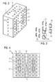
- FIG. 1 is a supporting structure 1 of a not shown in the entirety permanent magnetic drive system to operate a switching device to see.
- This structure 1 comprises a cuboidal frame composed of two magnetic yokes 2 and 3 with the interposition of two bearing plates 4 and 5.
- Both magnetic yokes 2 and 3 are designed mirror-symmetrically and have at both ends in each case angled by 90 degrees yoke legs, so that they are designed approximately U-shaped with respect to their basic shape.
- the flat end surfaces of the oppositely directed yoke legs of the magnetic yokes 2 and 3 lie flat against the facing side surface of the bearing plate 4 and at the bottom of the facing side surface of the bearing plate 5, wherein the corresponding yoke legs are connected to each other via the bearing plates 4 and 5 respectively.
- the armature 8 also comprises two armature guide rods 9 which project centrally from the upper side or the lower side of the armature block and are arranged geometrically coaxial with one another.
- the armature guide rods 9 pass through a bearing bore 10 in their associated bearing plate 4 and 5 with little circumferential clearance and stand out with an end portion of the bearing bore 10 of their bearing plate 4 and 5, so that the armature 8 is vertically linearly slidably guided by the guide rods 9.
- the magnetic frame would be in the assembly still provided with two coils between the pole legs and the yoke legs, by the magnetic field of the armature 8 would be shifted with appropriate polarity after overcoming its adhesion to the bearing plate 5 in its upper end position, in which its feed by striking the bottom the bearing plate 4 would be limited. After reversal of the polarity of the magnetic field he would be depressed after overcoming the adhesion by magnetic forces back down to the end position shown on the bearing plate 5 and held in the contact position.
- the mode of action of such magnetic drives is known as such, so that no further explanation is provided here.
- the magnetic yokes 2 and 3 consist here of a plurality of thin yoke plates, which are joined to the shown thick Jochblechstapel.
- the armature 8 and the bearing plates 4 and 5 consist of blocks of ferromagnetic material of known type, in particular of a corresponding iron alloy.
- a plurality of channels (hollow channels) 11, 12 and 13 are integrated into the solid block of the armature 8, here a matching Diameter of example, 4 mm, all are formed as through holes and differ only in their length, since they pass through the block of the armature 8 in different directions.
- the hollow channels 11, 12 and 13 may alternatively be formed as blind holes, which are drilled from both side surfaces.
- the hollow channels 11 go from the upper end face of the armature 8, parallel to the central longitudinal axis of the armature guide rods 9 and thus at right angles to the flat end face until they open on the opposite end.
- two rows each having six hollow channels 11 are provided, wherein the hollow channels 11 in each of the two rows each have a predeterminable distance of, for example, about 10 mm to the adjacent hollow channel 11.
- These rows extend parallel to the long side edges of the end faces and on opposite sides of a centrally located on the front side blind hole 14 with internal thread, in which the armature guide rod 9 or top and bottom two armature guide bolt is screwed or are.
- the hollow channels 12 are arranged, which emanate from a narrow side of the armature 8 and open on the opposite narrow side of the armature 8. These total of five hollow channels 12 form a straight row, which is arranged centrally between the long side edges of the narrow side, as in connection with FIGS. 2 and 4 beyond doubt. This hollow channels 12 but thereby also run centrally between the two rows with the hollow channels 11 and also penetrate the assembly plane of the armature guide rods 9. If no weakening of the bore wall of the blind holes 14 should be made, the hollow channels 12 can therefore alternatively as blind holes be formed and terminate at a distance in front of the blind hole 14.
- Such blind holes as hollow channels 12 should then end as possible at the same distance from the blind hole 14 as the lateral distance of the hollow channels 11 on the front side of the armature 8. This distance is in the frontal plan view according to FIG. 2 clearly visible. In this case, however, the hollow channels 12 would have to be drilled from the opposite end sides, which would result in a corresponding additional expenditure in the production of the armature 8.
- the hollow channels 13 are introduced, which all extend at right angles to the longitudinal center plane of the armature 8.
- the hollow channels 13 go from one broad side of the armature 8 and open into the opposite broad side.
- the hole pattern on the broad side comprises two rectangular hole fields, which consist of three parallel rows, each with seven or five hollow channels 13, wherein the hollow channels 13 in the row and laterally have a matching distance from each other.
- the three parallel rows each have seven hollow channels 13.
- a single hollow channel 13 ' is additionally centrally arranged, which also forms a through hole connecting the broad sides.
- the hollow passage 13 ' in this case a solid material area of the anchor block, which has remained between the ends of the two blind holes 14.
- hollow channels in the armature 8 are also in the bearing plates 4 and 5 hollow channels 15, which extend axially parallel to the hollow channels 11.
- hollow channels 15 two rows each having six hollow channels 15 are provided, which are preferably arranged congruent to the hollow channels 11 in the armature 8.
- the armature 8 For low-friction guidance of the armature 8 between the permanent magnets 6 and 7 is arranged between the armature 8 and the respective permanent magnet surface designed as a sliding foil 16 sliding member.
- the sliding foil 16 is magnetically fixed to the respective permanent magnet 6, 7, z. B. glued.
- the dimensions of the sliding film 16 approximately correspond to the surface of the permanent magnets 6, 7.
- the sliding film 16 is about 0.5 mm thick. In this case, the thickness of the sliding film 16 in particular depends on the clearance between the armature 8 and the permanent magnets 6, 7.
- recesses 17 are introduced into the surface of the armature 8, in which the in FIG. 3 shown, designed as a sliding body 18 alternative sliding elements and optionally spacers 19 can be arranged.
- Below the recesses 17 each have a hollow channel 13 is inserted into the armature 8.
- the number of spacers 19, which are formed for example as spacers, depends significantly on the ceremoniesshus and the game between the armature 8 and permanent magnets 6, 7 from.
- a Be provided helical compression spring which is inserted into a bore, not shown, in particular a hollow channel 13 below the recess 17, z. B. is screwed and presses the slider 18 against the permanent magnet surface of the respective permanent magnet 6 and 7 respectively.
- FIGS. 5 and 6 show an alternative embodiment for an armature 6 with differently shaped hole fields and without lateral hollow channels 12.
- the recesses 17 for receiving sliding bodies 18 and optionally spacer elements 19 are here introduced as elongated grooves in the surface of the armature 8.
Landscapes
- Physics & Mathematics (AREA)
- Electromagnetism (AREA)
- Engineering & Computer Science (AREA)
- Power Engineering (AREA)
- Linear Motors (AREA)
- Electromagnets (AREA)
- Driving Mechanisms And Operating Circuits Of Arc-Extinguishing High-Tension Switches (AREA)
Description
- Die Erfindung bezieht sich auf ein magnetisches Antriebssystem für eine Schalteinrichtung der im Oberbegriff von Patentanspruch 1 angegebenen Art.
- Eine derartiges bipolares Antriebssystem ist z. B. aus der
DE 197 09 089 A1 bereits bekannt. Der Anker besteht hierbei aus einem massiven magnetischen Eisenwerkstoff, wodurch er sich kostengünstiger fertigen lässt als ein aus geschichteten Elektroblechen zusammengesetzter Anker und häufig auch eine größere Langzeitstabilität aufweisen wird. Dafür hat der massive Anker an sich den Nachteil, dass gegenüber Ankern aus geschichtetem Elektroblech mehr Wirbelstromverluste auftreten und eine stärkere Remanenz vorhanden ist, die u. a. das Lösen der Schaltkontakte beim Umschalten erschwert. Um die Wirbelstromverluste zu reduzieren, ist der Anker mit länglichen Hohlkanälen versehen, die aus schmalen Schlitzen bestehen und sich in Vorschubrichtung des Ankers und somit in Richtung der magnetischen Feldlinien erstrecken. - Aus der
Patentschrift US 3,755,766 ist ein bistabiler elektromagnetischer Aktuator bekannt, bei dem ein Anker mit einer dünnen Schicht Teflon versehen ist, um ein leichtes Gleiten des Ankers zu ermöglichen. - Bei mono- oder bipolaren magnetischen Antriebssystemen, besonders bei permanentmagnetisch gepolten, wird der Anker meist über eine zentrale Achse oder zwei Achsbolzen im Magnetsystem geführt. Aus der älteren deutschen Patentanmeldung
10 2007 028 203.8 ist ein bipolares magnetisches Antriebssystem für eine Schalteinrichtung bekannt, bei der der Anker über zwei Achsbolzen im Magnetsystem geführt wird. Dabei kann es bei der Führung des Ankers zu einer Verkantung des Ankers im Magnetsystem kommen. Darüber hinaus kann aufgrund des Führungsmaßes und des daraus resultierenden Spieles zwischen Anker und Permanentmagnet der Anker mit zwei seiner Kanten an den Jochflächen anliegen und über Schaltbewegung mechanisch auf diese einwirken. Dies führt zu einem Schaben des Ankers und zu hohen Reibungskräften, welche die spröden Permanentmagneten beschädigen können. Zur Vermeidung des Schabens an den von den Permanentmagneten gebildeten Jochflächen ist es ferner bekannt, Blechlagen anzuordnen. Diese führen aber zu erheblichen Reibungskräften, die sogar zu einem Schaltversagen führen können. - Der Erfindung liegt daher die Aufgabe zugrunde, ein magnetisches Antriebssystem der im Oberbegriff von Anspruch 1 angegebenen Art dahingehend weiterzuentwickeln, dass ein Verkanten weitgehend verhindert und eine hohe Schaltstabilität ermöglicht ist.
- Diese Aufgabe wird durch die Merkmale von Patentanspruch 1 gelöst.
- Vorteilhafte Ausgestaltungen der Erfindung sind Gegenstand der abhängigen Ansprüche.
- Das erfindungsgemäße magnetische Antriebssystem für eine Schalteinrichtung umfasst ein Magnetjoch, in dem ein massiver Anker aus magnetischem Werkstoff zwischen zwei entgegen gesetzten Endlagen linear schiebegeführt ist, und wenigstens einen Permanentmagneten zur Erzeugung eines magnetischen Flusses in dem Magnetjoch und wenigstens eine Spule, durch die der Anker zwischen seinen Endlagen hin- und her bewegbar ist. Dabei ist der Anker zur Vermeidung von Wirbelstromverlusten mit länglichen Hohlkanälen versehen. Erfindungsgemäß ist zwischen verschiebbarem Anker und einer in Richtung des Ankers weisenden Permanentmagnetoberfläche ein Gleitelement angeordnet.
- Durch die Anordnung eines Gleitelements zwischen den Führungsflächen ist der Anker weitgehend spaltfrei und reibungsarm geführt. Hierdurch sind stabile Schaltzeiten und hohe Schaltspielzahlen ermöglicht sowie Beschädigungen der spröden Permanentmagneten weitgehend vermieden. Insbesondere kommt es zu keiner abrasiv bedingten Beschädigung der Permanentmagneten. Zudem können sich keine Verschleißpartikel auf der oder den Endflächen des Magnetjochs ablagern, die eine Verminderung des Schalthubes des Ankers bewirken würden. Ferner setzten sich auch im Spalt zwischen Anker und Permanentmagnet keine Verschleißpartikel fest, so dass es zu keiner undefinierbaren Beeinflussung der Schaltzeiten durch Reibung kommen kann. Zusammenfassend wird hierdurch die Langzeitstabilität und Betriebssicherheit des magnetischen Antriebssystems und des über dieses angetriebenen Schaltgerätes erhöht.
- Zweckmäßigerweise ist das Gleitelement ankerseitig oder magnetseitig angeordnet, insbesondere fixierbar. Dabei ist das Gleitelement bevorzugt einseitig, d.h. entweder ankerseitig oder magnetseitig, fixiert, wodurch der Anker reibungsarm geführt werden kann.
- Eine mögliche Ausführungsform sieht vor, dass das Gleitelement als eine Gleitfolie ausgebildet ist. Bevorzugt ist die Gleitfolie magnetseitig fixiert, so dass der Anker reibungsarm entlang der Gleitfolie geführt werden kann. Dabei weist die Gleitfolie insbesondere der Oberfläche des zugehörigen Permanentmagneten entsprechende Abmessungen auf. Auch können geringere Abmessungen für die Gleitfolie gewählt werden. An die Oberfläche des Permanentmagnets angepasste Abmessungen für die Gleitfolie ermöglichen ein flächiges und somit stabiles Fixieren der Gleitfolie am Permanentmagneten sowie eine besonders reibungsarme Führung des Ankers entlang der Gleitfolie.
- Bei einer Ausführungsform eines von zwei Permanentmagneten umgebenen Ankers bzw. eines in einem Hohlraum eines Permanentmagneten geführten Ankers ist vorzugsweise auf jedem der Permanentmagnetoberflächen jeweils eine Gleitfolie fixiert. Dies ermöglicht eine besonders gute Führung bei weitgehend geringen Reibungskräften.
- Bevorzugt ist die Gleitfolie aus einem Fluorkunststoff, insbesondere aus Perfluoralkoxy-Copolymer (PFA), Perfluorethylenpropylen-Copolymer (FEP) oder Polytetrafluorethylen (PTFE) gebildet. Eine aus einem derartigen festen und eine gleitende Oberfläche ermöglichenden Material gebildete Gleitfolie ist weitgehend verschleißfrei und als Gleitmittel oder -element zur reibungsarmen Führung des harten Ankers besonders gut geeignet.
- In einer weiteren Ausführungsform weist die Gleitfolie eine Dicke von 0.5 mm auf. Hierdurch kann ein durch Fertigungstoleranzen bedingtes Spiel zwischen Anker und Permanentmagnetoberfläche ausgeglichen werden, so dass der Anker weitgehend spaltfrei geführt werden kann und ein Festsetzen von Verschleißpartikeln im Spalt vermieden ist.
- Erfindungsgemäß ist als Gleitelement mindestens ein Gleitkörper vorgesehen. Dabei ist der Gleitkörper ankerseitig, in einer Aussparung des Ankers angeordnet. Auch können mehrere Gleitkörper zur reibungsarmen Führung in einer oder mehreren Aussparungen des Ankers angeordnet sein.
- Zweckmäßigerweise ist oder sind der oder die Aussparungen seitlich auf den Breitseiten des Ankers in dessen Oberfläche eingebracht, wodurch der Anker weitgehend reibungsarm entlang der Permanentmagnetoberfläche/n geführt werden kann.
- Eine mögliche Ausführungsform für die Aussparung sieht vor, dass diese als eine oder mehrere Rinnen ausgebildet ist. Dabei weist die jeweilige Aussparung eine an die Form, insbesondere an die Außenabmessungen des Gleitkörpers weitgehend angepasste Form, insbesondere Innenabmessungen auf, so dass der Gleitkörper weitgehend formschlüssig in die Aussparung einbracht werden kann und in dieser aus dieser kurz herausragend angeordnet ist. Bevorzugt sind mehrere Gleitkörper parallel neben- und/oder übereinander in jeweils zugehörige Aussparungen angeordnet.
- Zur Einstellung des Führungsmaßes und weitgehenden Reduzierung eines Spiels zwischen verschiebbarem Anker und Permanentmagnetoberfläche ist mindestens ein Distanzelement vorgesehen. Das Distanzelement ist bevorzugt unterhalb des Gleitkörpers in der Aussparung angeordnet, so dass der Gleitkörper aus der Aussparung hinausragt und eine reibungsarme Führung des Ankers an der Permanentmagnetoberfläche ermöglicht.
- Bei einer Ausbildung des Distanzelementes als Distanzblech ist dieses unterhalb des Gleitkörpers in die jeweilige Aussparung für den Gleitkörper angeordnet, wodurch der Gleitkörper an die Permanentmagnetoberfläche gedrückt wird. Bei einer alternativen Ausbildung des Distanzelementes als Schraubendruckfeder ist diese in eine Bohrung unterhalb der jeweiligen Aussparung angeordnet, insbesondere in diese geschraubt. Dabei drückt die Schraubendruckfeder den Gleitkörper an die Permanentmagnetoberfläche.
- Von der technischen Wirkung her und auch fertigungstechnisch günstig ist der Gleitkörper bevorzugt aus einem glasfaserverstärkten Thermoplast, insbesondere aus einem Fluorkunststoff, z. B. Perfluoralkoxy-Copolymer (PFA), Perfluorethylenpropylen-Copolymer (FEP), Polytetrafluorethylen (PTFE), oder Polyoxymethylen oder Polyacetal (= POM) gebildet.
- Weitere zweckmäßige Ausgestaltungen und Vorteile der Erfindung sind der nachfolgenden Beschreibung eines Ausführungsbeispiels unter Bezug auf die Figuren der Zeichnung zu entnehmen, wobei einander entsprechende Bauteile mit gleichen Bezugszeichen versehen sind.
- In den Zeichnungen zeigen:
- Fig. 1
- eine Tragstruktur eines magnetischen Antriebssystems in perspektivischer Schrägansicht,
- Fig. 2
- einen Anker der Tragstruktur mit mehreren in die Oberfläche der Breitseite eingebrachten Aussparungen zur Aufnahme von Gleitkörpern in perspektivischer Einzelansicht schräg von rechts,
- Fig. 3
- mehrere in Aussparungen des Anker gemäß
Figur 2 einsetzbare Distanzelemente und Gleitkörper in perspektivischer Einzelansicht schräg von rechts, - Fig. 4
- eine Frontalansicht einer Breitseite des Ankerblocks in
Fig. 2 mit in gestrichelter Darstellung angedeutetem Verlauf der Lochreihen, - Fig. 5
- eine weitere mögliche Ausführungsform für einen Anker der Tragstruktur mit mehreren in die Oberfläche der Breitseite eingebrachten Aussparungen zur Aufnahme von Gleitkörpern in perspektivischer Einzelansicht schräg von rechts, und
- Fig. 6
- eine Frontalansicht einer Breitseite des Ankerblocks in
Fig. 5 mit in gestrichelter Darstellung angedeutetem Verlauf der Lochreihen. - Einander entsprechende Teile sind in allen Figuren mit den gleichen Bezugszeichen versehen.
- In
Figur 1 ist eine tragende Struktur 1 eines nicht in der Gesamtheit dargestellten permanentmagnetischen Antriebssystems zur Betätigung einer Schalteinrichtung zu sehen. Diese Struktur 1 umfasst einen quaderförmigen Rahmen, der aus zwei Magnetjochen 2 und 3 unter Zwischenfügung von zwei Lagerplatten 4 und 5 zusammengesetzt ist. Beide Magnetjoche 2 und 3 sind spiegelsymmetrisch gestaltet und besitzen an den beiden Enden jeweils um 90 Grad abgewinkelte Jochschenkel, so dass sie hinsichtlich ihrer Grundform etwa U-förmig gestaltet sind. Die planen Endflächen der gegeneinander gerichteten Jochschenkel der Magnetjoche 2 und 3 liegen oben flächig an der zugewandten Seitenfläche der Lagerplatte 4 und unten an der zugewandten Seitenfläche der Lagerplatte 5 an, wobei die korrespondierenden Jochschenkel über die Lagerplatten 4 bzw. 5 miteinander verbunden sind. Im Mittelbereich zwischen den Jochschenkeln ragt von den Magnet jochen 2 und 3 jeweils ein vorspringender Polschenkel ab, wobei die einander gegenüberliegenden Polschenkel entsprechend den Jochschenkeln gegeneinander gerichtet sind. Auf den einander mit Abstand gegenüberliegenden Enden der Polschenkel sind plattenförmige Permanentmagnete 6 bzw. 7 befestigt. - Zwischen den planparallelen Permanentmagneten 6 und 7 liegt mit geringem Abstand zu diesen ein quaderförmiger Anker 8 im Jochrahmen, der in der gezeichneten Position an der Lagerplatte 5 aufliegt. Der Anker 8 umfasst auch zwei Ankerführungsstangen 9 die mittig von der Oberseite bzw. der Unterseite des Ankerblocks abstehen und geometrisch koaxial zueinander angeordnet sind. Die Ankerführungsstangen 9 durchsetzen eine Lagerbohrung 10 in der ihnen zugeordneten Lagerplatte 4 bzw. 5 mit wenig Umfangsspiel und stehen mit einem Endbereich aus der Lagerbohrung 10 ihrer Lagerplatte 4 bzw. 5 heraus, so dass der Anker 8 mittels der Führungsstangen 9 vertikal linear schiebegeführt ist. Der Magnetrahmen wäre im Zusammenbau noch mit zwei Spulen zwischen den Polschenkeln und den Jochschenkeln versehen, durch deren Magnetfeld der Anker 8 bei entsprechender Polrichtung nach Überwindung seiner Anhaftung an der Lagerplatte 5 in seine obere Endlage verschoben würde, in der sein Vorschub durch Anschlagen an der Unterseite der Lagerplatte 4 begrenzt würde. Nach Umkehrung der Polrichtung des Magnetfeldes würde er nach Überwindung der Anhaftung durch Magnetkräfte wieder nach unten in die gezeigte Endlage auf die Lagerplatte 5 niedergedrückt und in der Anlagestellung gehalten. Die Wirkungsweise solcher Magnetantriebe ist als solche bekannt, so dass hier auf weitergehende Erläuterungen verzichtet wird.
- Die Magnetjoche 2 und 3 bestehen hier aus einer Vielzahl dünner Jochbleche, die zu dem gezeigten, dicken Jochblechstapel gefügt sind. Demgegenüber bestehen der Anker 8 sowie die Lagerplatten 4 und 5 aus Blöcken ferromagnetischen Materials bekannter Art, insbesondere aus einer entsprechenden Eisenlegierung.
- Zur Reduzierung der Wirbelstromverluste und der Remanenz des Ankers 8 sowie der Lagerplatten 4 und 5 sind in den massiven Block des Ankers 8 eine Vielzahl von Kanälen (Hohlkanälen) 11, 12 und 13 integriert, die hier einen übereinstimmenden Durchmesser von beispielsweise 4 mm aufweisen, alle als Durchgangsbohrungen ausgebildet sind und sich nur hinsichtlich ihrer Länge unterscheiden, da sie den Block des Ankers 8 in unterschiedlichen Richtungen durchsetzen. Die Hohlkanäle 11, 12 und 13 können alternativ auch als Sacklochbohrungen ausgebildet sein, die von beiden Seitenflächen aus gebohrt werden.
- Wie in Verbindung mit der
Figur 2 deutlicher zu erkennen ist, gehen die Hohlkanäle 11 von der oberen Stirnseite des Ankers 8 aus, verlaufen parallel zur Mittellängsachse der Ankerführungsstangen 9 und somit rechtwinklig zur planen Stirnseite bis sie auf der gegenüberliegenden Stirnseite münden. Dabei sind zwei Reihen mit jeweils sechs Hohlkanälen 11 vorhanden, wobei die Hohlkanäle 11 in jeder der beiden Reihen jeweils einen vorgebbaren Abstand von beispielsweise ca. 10 mm zum benachbarten Hohlkanal 11 aufweisen. Diese Reihen verlaufen parallel zu den langen Seitenkanten der Stirnseiten und auf entgegen gesetzten Seiten einer mittig in auf der Stirnseite angeordnete Sacklochbohrung 14 mit Innengewinde, in welche die Ankerführungsstange 9 oder ober- und unterseitig zwei Ankerführungsbolzen hineingedreht ist bzw. sind. Quer zu diesen Hohlkanälen 11 sind die Hohlkanäle 12 angeordnet, die von einer Schmalseite des Ankers 8 ausgehen und auf der gegenüberliegenden Schmalseite des Ankers 8 münden. Diese insgesamt fünf Hohlkanäle 12 bilden eine gerade Reihe, die mittig zwischen den langen Seitenkanten der Schmalseite angeordnet ist, wie in Verbindung mitFiguren 2 und 4 zweifelsfrei zu sehen ist. Diese Hohlkanäle 12 verlaufen dadurch aber auch mittig zwischen den beiden Reihen mit den Hohlkanälen 11 und durchdringen auch die Anordnungsebene der Ankerführungsstangen 9. Falls keine Schwächung der Bohrungswand der Sacklochbohrungen 14 erfolgen soll, können die Hohlkanäle 12 deshalb alternativ auch als Sacklochbohrungen ausgebildet sein und in einem Abstand vor der Sacklochbohrung 14 enden. Solche Sacklochbohrungen als Hohlkanäle 12 sollten dann möglichst im gleichen Abstand von der Sacklochbohrung 14 enden wie der seitliche Abstand der Hohlkanäle 11 auf der Stirnseite des Ankers 8. Dieser Abstand ist in der frontalen Draufsicht gemäßFigur 2 gut zu erkennen. In diesem Fall müssten die Hohlkanäle 12 aber von den entgegen gesetzten Stirnseiten aus gebohrt werden, was einen entsprechenden Mehraufwand bei der Herstellung des Ankers 8 zur Folge hätte. - Ebenfalls quer zu den Hohlkanälen 11 und in erheblich größerer Anzahl sind die Hohlkanäle 13 eingebracht, die sich alle rechtwinklig zur Längsmittelebene des Ankers 8 erstrecken. Dabei gehen die Hohlkanäle 13 von einer Breitseite des Ankers 8 aus und münden in die gegenüberliegende Breitseite ein. Das Lochbild auf der Breitseite umfasst dabei zwei rechteckige Lochfelder, die aus drei parallelen Reihen mit jeweils sieben bzw. fünf Hohlkanälen 13 bestehen, wobei die Hohlkanäle 13 in der Reihe und seitlich einen übereinstimmenden Abstand voneinander aufweisen. Dabei weisen die jeweils drei parallelen Reihen sieben Hohlkanäle 13 auf. Diese Lochfelder liegen beidseitig eines Mittelbereichs des Ankers 8, in dem die Ankerführungsstangen 9 angeordnet sind.
- Zwischen den beiden Lochfeldern aus Hohlkanälen 13 ist zusätzlich zentral ein einzelner Hohlkanal 13' angeordnet, der ebenfalls eine die Breitseiten verbindende Durchgangsbohrung bildet. Wie aus der Frontalansicht nach
Figur 5 in Verbindung mit der Schnittdarstellung nachFigur 6 zu ersehen ist, passiert der Hohlkanal 13' hierbei einen Vollmaterialbereich des Ankerblocks, der zwischen den Enden der beiden Sacklochbohrungen 14 verblieben ist. Somit wird die Stabilität des Ankers 8 durch den Hohlkanal 13' nicht nennenswert beeinträchtigt. - Neben den Hohlkanälen im Anker 8 befinden sich auch in den Lagerplatten 4 und 5 Hohlkanäle 15, die sich achsparallel zu den Hohlkanälen 11 erstrecken. Von den Hohlkanälen 15 sind zwei Reihen mit jeweils sechs Hohlkanälen 15 vorhanden, die vorzugsweise kongruent zu den Hohlkanälen 11 im Anker 8 angeordnet sind.
- Zur reibungsarmen Führung des Ankers 8 zwischen den Permanentmagneten 6 und 7 ist zwischen dem Anker 8 und der jeweiligen Permanentmagnetoberfläche ein als Gleitfolie 16 ausgebildetes Gleitelement angeordnet. Die Gleitfolie 16 ist magnetseitig am jeweiligen Permanentmagneten 6, 7 fixiert, z. B. geklebt. Die Abmessungen der Gleitfolie 16 entsprechen in etwa der Oberfläche der Permanentmagneten 6, 7. Die Gleitfolie 16 ist etwa 0.5 mm dick. Dabei hängt die Dicke der Gleitfolie 16 insbesondere vom Spiel zwischen Anker 8 und Permanentmagneten 6, 7 ab.
- Im Oberflächenbereich der mittleren Lochreihe mit sieben Hohlkanälen 13 der jeweils drei parallelen Lochreihen des Ankers 8 sind Aussparungen 17 in die Oberfläche des Ankers 8 eingebracht, in welche die in
Figur 3 gezeigten, als Gleitkörper 18 ausgebildeten alternativen Gleitelemente und gegebenenfalls Distanzelemente 19 anordbar sind. Unterhalb der Aussparungen 17 ist jeweils ein Hohlkanal 13 in den Anker 8 eingebracht. Die Anzahl der Distanzelemente 19, welche beispielsweise als Distanzbleche ausgebildet sind, hängt dabei maßgeblich vom Führungsmaß und dem Spiel zwischen Anker 8 und Permanentmagneten 6, 7 ab. In einer alternativen, nicht näher dargestellten Ausführungsform kann anstelle der als Distanzbleche ausgebildeten Distanzelemente 19 eine Schraubendruckfeder vorgesehen sein, die in eine nicht dargestellte Bohrung, insbesondere einen Hohlkanal 13 unterhalb der Aussparung 17 eingesetzt, z. B. eingeschraubt wird und die den Gleitkörper 18 gegen die Permanentmagnetoberfläche des betreffenden Permanentmagneten 6 bzw. 7 drückt. -
Figuren 5 und 6 zeigen eine alternative Ausführungsform für einen Anker 6 mit unterschiedlich ausgeprägten Lochfeldern und ohne seitliche Hohlkanäle 12. Die Aussparungen 17 zur Aufnahme von Gleitkörpern 18 und gegebenenfalls Distanzelementen 19 sind hier als längliche Rinnen in die Oberfläche des Ankers 8 eingebracht. -
- 1
- Struktur
- 2, 3
- Magnet jochen
- 4, 5
- Lagerplatte
- 6, 7
- Permanentmagnete
- 8
- Anker
- 9
- Führungsstangen
- 10
- Lagerbohrung
- 11, 12, 13, 13', 15
- Hohlkanäle
- 14
- Sacklochbohrung
- 16
- Gleitfolie
- 17
- Aussparungen
- 18
- Gleitkörper
- 19
- Distanzelemente
Claims (7)
- Magnetisches Antriebssystem für eine Schalteinrichtung mit einem Magnetjoch (2, 3), in dem ein massiver Anker (8) aus magnetischem Werkstoff zwischen zwei entgegengesetzten Endlagen linear schiebegeführt ist, mit wenigstens einem Permanentmagneten (6, 7) zur Erzeugung eines magnetischen Flusses in dem Magnetjoch (2, 3) und mit wenigstens einer Spule, durch die der Anker (8) zwischen seinen Endlagen hin- und her bewegbar ist, wobei der Anker (8) zur Vermeidung von Wirbelstromverlusten mit länglichen Hohlkanälen (11, 12, 13, 13') versehen ist,
dadurch gekennzeichnet, dass zwischen verschiebbarem Anker (8) und einer in Richtung des Ankers (8) weisenden Permanentmagnetoberfläche als Gleitelement mindestens ein Gleitkörper (18) angeordnet ist, wobei der oder die Gleitkörper (18) in einer oder mehreren Aussparungen (17) des Ankers (8) angeordnet ist bzw. sind. - Magnetisches Antriebssystem nach Anspruch 1,
dadurch gekennzeichnet, dass der oder die Aussparungen (17) seitlich auf den Breitseiten des Ankers (8) in dessen Oberfläche eingebracht ist bzw. sind. - Magnetisches Antriebssystem nach Anspruch 1 oder 2,
dadurch gekennzeichnet, dass der oder die Aussparungen (17) als eine oder mehrere Rinnen ausgebildet ist bzw. sind. - Magnetisches Antriebssystem nach einem der Ansprüche 1 bis 3,
dadurch gekennzeichnet, dass der Gleitkörper (18) aus einem glasfaserverstärkten Thermoplast, insbesondere aus einem Fluorkunststoff oder Polyoxymethylen oder Polyacetal (= POM) gebildet ist. - Magnetisches Antriebssystem nach einem der Ansprüche 1 bis 4,
dadurch gekennzeichnet, dass mindestens ein Distanzelement (19) zur Einstellung eines Führungsmaßes zwischen verschiebbarem Anker (8) und Permanentmagnetoberfläche vorgesehen sind. - Magnetisches Antriebssystem nach Anspruch 5,
dadurch gekennzeichnet, dass bei einer Ausbildung des Distanzelementes (19) als Distanzblech dieses in die jeweilige Aussparung (17) unterhalb des Gleitkörpers (18) angeordnet ist, wodurch der Gleitkörper (18) an die Permanentmagnetoberfläche gedrückt wird. - Magnetisches Antriebssystem nach Anspruch 5,
dadurch gekennzeichnet, dass bei einer Ausbildung des Distanzelementes (19) als Schraubendruckfeder diese in eine Bohrung, insbesondere einen Hohlkanal (13) unterhalb der jeweiligen Aussparung (17) angeordnet ist und den Gleitkörper (18) an die Permanentmagnetoberfläche drückt.
Applications Claiming Priority (2)
| Application Number | Priority Date | Filing Date | Title |
|---|---|---|---|
| DE200710041969 DE102007041969C5 (de) | 2007-09-03 | 2007-09-03 | Magnetisches Antriebssystem für eine Schalteinrichtung |
| PCT/EP2008/061490 WO2009030664A1 (de) | 2007-09-03 | 2008-09-01 | Magnetisches antriebssystem für eine schalteinrichtung |
Publications (2)
| Publication Number | Publication Date |
|---|---|
| EP2183759A1 EP2183759A1 (de) | 2010-05-12 |
| EP2183759B1 true EP2183759B1 (de) | 2015-04-15 |
Family
ID=40280655
Family Applications (1)
| Application Number | Title | Priority Date | Filing Date |
|---|---|---|---|
| EP08803472.3A Active EP2183759B1 (de) | 2007-09-03 | 2008-09-01 | Magnetisches antriebssystem für eine schalteinrichtung |
Country Status (6)
| Country | Link |
|---|---|
| EP (1) | EP2183759B1 (de) |
| CN (1) | CN101796605B (de) |
| DE (1) | DE102007041969C5 (de) |
| ES (1) | ES2535868T3 (de) |
| PT (1) | PT2183759E (de) |
| WO (1) | WO2009030664A1 (de) |
Family Cites Families (10)
| Publication number | Priority date | Publication date | Assignee | Title |
|---|---|---|---|---|
| DE1905125U (de) * | 1964-09-23 | 1964-11-26 | Kienzle Apparate Gmbh | Tauchankermagnet. |
| US3755766A (en) * | 1972-01-18 | 1973-08-28 | Regdon Corp | Bistable electromagnetic actuator |
| CN1046815C (zh) * | 1991-10-04 | 1999-11-24 | 张凡 | 磁保持电磁铁 |
| CN1041868C (zh) * | 1992-10-27 | 1999-01-27 | 麦阀门有限公司 | 螺线管 |
| DE19709089A1 (de) * | 1997-03-06 | 1998-09-10 | Abb Patent Gmbh | Permanentmagnetischer Antrieb für einen Schalter |
| DE29706491U1 (de) * | 1997-04-11 | 1998-08-06 | FEV Motorentechnik GmbH & Co. KG, 52078 Aachen | Elektromagnetischer Aktuator mit wirbelstromarmem Anker |
| DE19805049A1 (de) * | 1998-02-09 | 1999-08-12 | Schultz Wolfgang E | Elektromagnet |
| CN2337667Y (zh) * | 1998-03-05 | 1999-09-08 | 高玉龙 | 分合闸电磁铁 |
| DE19821741C2 (de) * | 1998-05-14 | 2002-02-07 | Elektroteile Gmbh | Magnetankerlager, insbesondere für Proportionalmagnete und Schaltmagnete im Hydraulik- oder Pneumatikbetrieb und Verfahren zu seiner Herstellung |
| DE102007005434A1 (de) * | 2007-01-30 | 2008-07-31 | Svm Schultz Verwaltungs-Gmbh & Co. Kg | Doppeltwirkender elektromagnetischer Aktor |
-
2007
- 2007-09-03 DE DE200710041969 patent/DE102007041969C5/de not_active Expired - Fee Related
-
2008
- 2008-09-01 PT PT88034723T patent/PT2183759E/pt unknown
- 2008-09-01 WO PCT/EP2008/061490 patent/WO2009030664A1/de not_active Ceased
- 2008-09-01 EP EP08803472.3A patent/EP2183759B1/de active Active
- 2008-09-01 CN CN200880105383.1A patent/CN101796605B/zh active Active
- 2008-09-01 ES ES08803472.3T patent/ES2535868T3/es active Active
Also Published As
| Publication number | Publication date |
|---|---|
| ES2535868T3 (es) | 2015-05-18 |
| HK1145565A1 (en) | 2011-04-21 |
| PT2183759E (pt) | 2015-05-18 |
| WO2009030664A1 (de) | 2009-03-12 |
| CN101796605A (zh) | 2010-08-04 |
| EP2183759A1 (de) | 2010-05-12 |
| DE102007041969C5 (de) | 2010-09-30 |
| DE102007041969B3 (de) | 2009-04-09 |
| CN101796605B (zh) | 2013-03-27 |
Similar Documents
| Publication | Publication Date | Title |
|---|---|---|
| DE3334159C2 (de) | ||
| DE102010010801B4 (de) | Aktuator | |
| AT414183B (de) | Bistabile schaltvorrichtung | |
| DE102010036119A1 (de) | Elektromagnetisches Stellglied | |
| DE102015212817A1 (de) | Kontaktbrückenanordnung für ein elektrisches Schaltelement | |
| EP0072975B1 (de) | Elektromagnetisches Relais | |
| EP2165347B1 (de) | Magnetisches antriebssystem für eine schalteinrichtung | |
| EP2183759B1 (de) | Magnetisches antriebssystem für eine schalteinrichtung | |
| DE102018001243A1 (de) | Bistabiler elektromagnetischer Hubaktor sowie Drahtziehmaschine | |
| EP1897108B1 (de) | Elektrische schaltvorrichtung mit magnetischen verstellelementen für ein schaltelement | |
| EP0251075B1 (de) | Magnetventil für flüssige und gasförmige Medien | |
| EP3545185B1 (de) | Ventil zum dosieren eines gases | |
| DE3338602C2 (de) | ||
| EP3270021A1 (de) | Elektromagnetischer ventilantrieb, verfahren zu seiner herstellung und damit ausgestattetes magnetventil | |
| EP4202272A1 (de) | Fluidventil | |
| DE102020125757A1 (de) | Dosierpumpe | |
| DE102014109619A1 (de) | Stellvorrichtung | |
| DE102021211154B3 (de) | Aktoreinrichtung | |
| DE102004039985A1 (de) | Relais | |
| DE3627661A1 (de) | Gleichstrom-elektromagnet fuer eine translationsbewegung | |
| EP1805844A1 (de) | Elektrische schaltvorrichtung mit magnetischen verstellelementen | |
| AT220682B (de) | Koordinatenschalter | |
| DE102015010805A1 (de) | Elektromagnetischer Linearantrieb | |
| DE10241838B4 (de) | Haftmagnet | |
| DE202020104006U1 (de) | Fluidik-Bauteil |
Legal Events
| Date | Code | Title | Description |
|---|---|---|---|
| PUAI | Public reference made under article 153(3) epc to a published international application that has entered the european phase |
Free format text: ORIGINAL CODE: 0009012 |
|
| 17P | Request for examination filed |
Effective date: 20100208 |
|
| AK | Designated contracting states |
Kind code of ref document: A1 Designated state(s): AT BE BG CH CY CZ DE DK EE ES FI FR GB GR HR HU IE IS IT LI LT LU LV MC MT NL NO PL PT RO SE SI SK TR |
|
| AX | Request for extension of the european patent |
Extension state: AL BA MK RS |
|
| RIN1 | Information on inventor provided before grant (corrected) |
Inventor name: ERMISCH, JOCHEN Inventor name: VOLKMAR, RALF-REINER Inventor name: ERK, THOMAS Inventor name: HERING, UWE Inventor name: PETER, MARIANNE |
|
| DAX | Request for extension of the european patent (deleted) | ||
| RAP1 | Party data changed (applicant data changed or rights of an application transferred) |
Owner name: SIEMENS AKTIENGESELLSCHAFT |
|
| GRAP | Despatch of communication of intention to grant a patent |
Free format text: ORIGINAL CODE: EPIDOSNIGR1 |
|
| INTG | Intention to grant announced |
Effective date: 20141113 |
|
| GRAS | Grant fee paid |
Free format text: ORIGINAL CODE: EPIDOSNIGR3 |
|
| GRAA | (expected) grant |
Free format text: ORIGINAL CODE: 0009210 |
|
| AK | Designated contracting states |
Kind code of ref document: B1 Designated state(s): AT BE BG CH CY CZ DE DK EE ES FI FR GB GR HR HU IE IS IT LI LT LU LV MC MT NL NO PL PT RO SE SI SK TR |
|
| REG | Reference to a national code |
Ref country code: GB Ref legal event code: FG4D Free format text: NOT ENGLISH Ref country code: CH Ref legal event code: NV Representative=s name: SIEMENS SCHWEIZ AG, CH Ref country code: CH Ref legal event code: EP |
|
| REG | Reference to a national code |
Ref country code: IE Ref legal event code: FG4D Free format text: LANGUAGE OF EP DOCUMENT: GERMAN |
|
| REG | Reference to a national code |
Ref country code: AT Ref legal event code: REF Ref document number: 722382 Country of ref document: AT Kind code of ref document: T Effective date: 20150515 |
|
| REG | Reference to a national code |
Ref country code: ES Ref legal event code: FG2A Ref document number: 2535868 Country of ref document: ES Kind code of ref document: T3 Effective date: 20150518 Ref country code: PT Ref legal event code: SC4A Free format text: AVAILABILITY OF NATIONAL TRANSLATION Effective date: 20150416 |
|
| REG | Reference to a national code |
Ref country code: DE Ref legal event code: R096 Ref document number: 502008012892 Country of ref document: DE Effective date: 20150528 |
|
| REG | Reference to a national code |
Ref country code: SE Ref legal event code: TRGR |
|
| REG | Reference to a national code |
Ref country code: NL Ref legal event code: T3 |
|
| REG | Reference to a national code |
Ref country code: NL Ref legal event code: T3 |
|
| REG | Reference to a national code |
Ref country code: LT Ref legal event code: MG4D |
|
| PG25 | Lapsed in a contracting state [announced via postgrant information from national office to epo] |
Ref country code: LT Free format text: LAPSE BECAUSE OF FAILURE TO SUBMIT A TRANSLATION OF THE DESCRIPTION OR TO PAY THE FEE WITHIN THE PRESCRIBED TIME-LIMIT Effective date: 20150415 Ref country code: HR Free format text: LAPSE BECAUSE OF FAILURE TO SUBMIT A TRANSLATION OF THE DESCRIPTION OR TO PAY THE FEE WITHIN THE PRESCRIBED TIME-LIMIT Effective date: 20150415 Ref country code: NO Free format text: LAPSE BECAUSE OF FAILURE TO SUBMIT A TRANSLATION OF THE DESCRIPTION OR TO PAY THE FEE WITHIN THE PRESCRIBED TIME-LIMIT Effective date: 20150715 Ref country code: FI Free format text: LAPSE BECAUSE OF FAILURE TO SUBMIT A TRANSLATION OF THE DESCRIPTION OR TO PAY THE FEE WITHIN THE PRESCRIBED TIME-LIMIT Effective date: 20150415 |
|
| PG25 | Lapsed in a contracting state [announced via postgrant information from national office to epo] |
Ref country code: IS Free format text: LAPSE BECAUSE OF FAILURE TO SUBMIT A TRANSLATION OF THE DESCRIPTION OR TO PAY THE FEE WITHIN THE PRESCRIBED TIME-LIMIT Effective date: 20150815 Ref country code: LV Free format text: LAPSE BECAUSE OF FAILURE TO SUBMIT A TRANSLATION OF THE DESCRIPTION OR TO PAY THE FEE WITHIN THE PRESCRIBED TIME-LIMIT Effective date: 20150415 Ref country code: GR Free format text: LAPSE BECAUSE OF FAILURE TO SUBMIT A TRANSLATION OF THE DESCRIPTION OR TO PAY THE FEE WITHIN THE PRESCRIBED TIME-LIMIT Effective date: 20150716 |
|
| REG | Reference to a national code |
Ref country code: DE Ref legal event code: R097 Ref document number: 502008012892 Country of ref document: DE |
|
| PG25 | Lapsed in a contracting state [announced via postgrant information from national office to epo] |
Ref country code: DK Free format text: LAPSE BECAUSE OF FAILURE TO SUBMIT A TRANSLATION OF THE DESCRIPTION OR TO PAY THE FEE WITHIN THE PRESCRIBED TIME-LIMIT Effective date: 20150415 Ref country code: EE Free format text: LAPSE BECAUSE OF FAILURE TO SUBMIT A TRANSLATION OF THE DESCRIPTION OR TO PAY THE FEE WITHIN THE PRESCRIBED TIME-LIMIT Effective date: 20150415 |
|
| PLBE | No opposition filed within time limit |
Free format text: ORIGINAL CODE: 0009261 |
|
| STAA | Information on the status of an ep patent application or granted ep patent |
Free format text: STATUS: NO OPPOSITION FILED WITHIN TIME LIMIT |
|
| PG25 | Lapsed in a contracting state [announced via postgrant information from national office to epo] |
Ref country code: CZ Free format text: LAPSE BECAUSE OF FAILURE TO SUBMIT A TRANSLATION OF THE DESCRIPTION OR TO PAY THE FEE WITHIN THE PRESCRIBED TIME-LIMIT Effective date: 20150415 Ref country code: PL Free format text: LAPSE BECAUSE OF FAILURE TO SUBMIT A TRANSLATION OF THE DESCRIPTION OR TO PAY THE FEE WITHIN THE PRESCRIBED TIME-LIMIT Effective date: 20150415 Ref country code: SK Free format text: LAPSE BECAUSE OF FAILURE TO SUBMIT A TRANSLATION OF THE DESCRIPTION OR TO PAY THE FEE WITHIN THE PRESCRIBED TIME-LIMIT Effective date: 20150415 Ref country code: RO Free format text: LAPSE BECAUSE OF NON-PAYMENT OF DUE FEES Effective date: 20150415 |
|
| 26N | No opposition filed |
Effective date: 20160118 |
|
| PG25 | Lapsed in a contracting state [announced via postgrant information from national office to epo] |
Ref country code: LU Free format text: LAPSE BECAUSE OF FAILURE TO SUBMIT A TRANSLATION OF THE DESCRIPTION OR TO PAY THE FEE WITHIN THE PRESCRIBED TIME-LIMIT Effective date: 20150901 Ref country code: MC Free format text: LAPSE BECAUSE OF FAILURE TO SUBMIT A TRANSLATION OF THE DESCRIPTION OR TO PAY THE FEE WITHIN THE PRESCRIBED TIME-LIMIT Effective date: 20150415 |
|
| PG25 | Lapsed in a contracting state [announced via postgrant information from national office to epo] |
Ref country code: SI Free format text: LAPSE BECAUSE OF FAILURE TO SUBMIT A TRANSLATION OF THE DESCRIPTION OR TO PAY THE FEE WITHIN THE PRESCRIBED TIME-LIMIT Effective date: 20150415 |
|
| REG | Reference to a national code |
Ref country code: IE Ref legal event code: MM4A |
|
| PG25 | Lapsed in a contracting state [announced via postgrant information from national office to epo] |
Ref country code: IE Free format text: LAPSE BECAUSE OF NON-PAYMENT OF DUE FEES Effective date: 20150901 |
|
| REG | Reference to a national code |
Ref country code: FR Ref legal event code: PLFP Year of fee payment: 9 |
|
| PG25 | Lapsed in a contracting state [announced via postgrant information from national office to epo] |
Ref country code: MT Free format text: LAPSE BECAUSE OF FAILURE TO SUBMIT A TRANSLATION OF THE DESCRIPTION OR TO PAY THE FEE WITHIN THE PRESCRIBED TIME-LIMIT Effective date: 20150415 |
|
| PG25 | Lapsed in a contracting state [announced via postgrant information from national office to epo] |
Ref country code: HU Free format text: LAPSE BECAUSE OF FAILURE TO SUBMIT A TRANSLATION OF THE DESCRIPTION OR TO PAY THE FEE WITHIN THE PRESCRIBED TIME-LIMIT; INVALID AB INITIO Effective date: 20080901 Ref country code: BG Free format text: LAPSE BECAUSE OF FAILURE TO SUBMIT A TRANSLATION OF THE DESCRIPTION OR TO PAY THE FEE WITHIN THE PRESCRIBED TIME-LIMIT Effective date: 20150415 |
|
| PG25 | Lapsed in a contracting state [announced via postgrant information from national office to epo] |
Ref country code: CY Free format text: LAPSE BECAUSE OF FAILURE TO SUBMIT A TRANSLATION OF THE DESCRIPTION OR TO PAY THE FEE WITHIN THE PRESCRIBED TIME-LIMIT Effective date: 20150415 |
|
| PG25 | Lapsed in a contracting state [announced via postgrant information from national office to epo] |
Ref country code: BE Free format text: LAPSE BECAUSE OF NON-PAYMENT OF DUE FEES Effective date: 20150930 |
|
| REG | Reference to a national code |
Ref country code: FR Ref legal event code: PLFP Year of fee payment: 10 |
|
| REG | Reference to a national code |
Ref country code: CH Ref legal event code: PCOW Free format text: NEW ADDRESS: WERNER-VON-SIEMENS-STRASSE 1, 80333 MUENCHEN (DE) |
|
| REG | Reference to a national code |
Ref country code: FR Ref legal event code: PLFP Year of fee payment: 11 |
|
| PGFP | Annual fee paid to national office [announced via postgrant information from national office to epo] |
Ref country code: DE Payment date: 20241118 Year of fee payment: 17 |
|
| PGFP | Annual fee paid to national office [announced via postgrant information from national office to epo] |
Ref country code: GB Payment date: 20241007 Year of fee payment: 17 |
|
| PGFP | Annual fee paid to national office [announced via postgrant information from national office to epo] |
Ref country code: ES Payment date: 20241219 Year of fee payment: 17 |
|
| PGFP | Annual fee paid to national office [announced via postgrant information from national office to epo] |
Ref country code: CH Payment date: 20241203 Year of fee payment: 17 |
|
| PGFP | Annual fee paid to national office [announced via postgrant information from national office to epo] |
Ref country code: PT Payment date: 20250814 Year of fee payment: 18 |
|
| PGFP | Annual fee paid to national office [announced via postgrant information from national office to epo] |
Ref country code: NL Payment date: 20250902 Year of fee payment: 18 Ref country code: IT Payment date: 20250924 Year of fee payment: 18 Ref country code: TR Payment date: 20250825 Year of fee payment: 18 |
|
| PGFP | Annual fee paid to national office [announced via postgrant information from national office to epo] |
Ref country code: FR Payment date: 20250915 Year of fee payment: 18 Ref country code: AT Payment date: 20250818 Year of fee payment: 18 |
|
| PGFP | Annual fee paid to national office [announced via postgrant information from national office to epo] |
Ref country code: SE Payment date: 20250904 Year of fee payment: 18 |
|
| REG | Reference to a national code |
Ref country code: CH Ref legal event code: U11 Free format text: ST27 STATUS EVENT CODE: U-0-0-U10-U11 (AS PROVIDED BY THE NATIONAL OFFICE) Effective date: 20251210 |